Review

Bio-Waste as a Substitute for the Production of Carbon Dioxide Adsorbents: A Review

by
Marcelina Sołtysik
*,
Izabela Majchrzak-Kucęba
* and
Dariusz Wawrzyńczak
Department of Advanced Energy Technologies, Faculty of Infrastructure and Environment, Czestochowa University of Technology, Dabrowskiego Street 73, 42-201 Częstochowa, Poland
*
Authors to whom correspondence should be addressed.
Energies 2022, 15(19), 6914; https://doi.org/10.3390/en15196914
Submission received: 23 August 2022 / Revised: 13 September 2022 / Accepted: 18 September 2022 / Published: 21 September 2022
(This article belongs to the Topic CO2 Capture and Renewable Energy)

Abstract

:
Bioadsorbent, obtained as a result of the processing of bio-waste, has recently gained popularity as a material that adsorbs greenhouse gases, mainly carbon dioxide. Bio-waste, mainly residues from food industry operations, is a waste to be landfilled or composted and can be a potential substrate for bioadsorbent production. Bioadsorbents used for carbon capture must, above all, have low production costs and high adsorption efficiency. This review covers popular bioadsorbents that have been tested for their ability to adsorb carbon dioxide. The paper compares bioadsorbent production methods, physicochemical properties, adsorption isotherms, surfaces, and their porosity. There is a lack of data in the literature on the topic of carbon dioxide adsorption on large-scale plants in the target environment. Therefore, further research needs to fill in the gaps to identify the promised potential of these bioadsorbents.

1. Introduction

Carbon dioxide (CO2) is a three-atomic gas molecule under environmental conditions. It is a relatively inert gas. It occurs naturally in the Earth’s atmosphere and plays an important role in photosynthesis, which makes it essential for plant life [1].
Unfortunately, overproduction from anthropogenic sources disrupts the natural cycle of carbon dioxide in the atmosphere. Huge amounts of this and other greenhouse gases pile up in the Earth’s atmosphere, trapping infrared radiation. This disrupts the climate economy, leading to climate change [2]. There are different sources of anthropogenic carbon dioxide, including the combustion of fossil fuels, emissions from industrial processes, treatment, and storage [3].
According to various assessments, the share of energy in the total carbon dioxide emissions ranges between 27% and 40%. It can be assumed that it is now one-third [4]. Since the flue gases from coal-fired power plants usually contain 15 vol. CO2 at a pressure of about 1 bar [5], the amount of CO2 adsorbed at a pressure of 0.15 bar and 298 K represents the operating parameters of the potential material/adsorbent for CO2 capture.
In order to regulate these emissions, techniques for carbon capture and storage (CCS) and carbon capture, utilization, and storage (CCUS) are used [6,7]. Carbon dioxide capture and separation is the first step in these techniques with an estimated cost of up to 80% of the total cost of CCS [8,9]. Unlike carbon sequestration, CCU is designed to use captured carbon dioxide and convert it into other substances or products. Recycling of carbon dioxide is the most difficult step in the entire process, but it has the potential to reduce the current annual global CO2 emissions by 10% [10]. To capture carbon dioxide, it must first be separated from other combustion gases. Various routes for carbon dioxide capture have been developed, but the post-combustion capture system has been found to be the most mature, flexible, and upgradeable process for a large number of existing fossil fuel-fired power plants. There are many technologies for carbon dioxide separation and capture, but the main component is an efficient adsorbent.
The adsorption process is a widespread, popular, environmentally friendly, safe, and simple process [11]. Finding a cheap and environmentally friendly adsorbent is an important stage in the processes of reducing carbon dioxide emissions to the atmosphere. The adsorbent should also have features that are easy to use, preferably cheap to produce [12]. The possibility of using waste to produce the adsorbent would be an opportunity to tackle two environmental problems in one process. The problem of waste as a global environmental threat is a new phenomenon, fully determined by human activity. Improper waste management contributes to climate change and air pollution, directly affecting many ecosystems and species. It is now necessary to view waste as a resource, reducing the need for new resources. Kitchen and garden waste make up the largest portion of municipal waste. Using them as a substrate for the preparation of carbon dioxide adsorbents will make it possible to partially manage them.
This review attempts to compare and evaluate the most common agricultural wastes used in bioadsorbent production. In particular, the paper examines the effectiveness of activators used in the production of bioadsorbents under different manufacturing conditions, as well as examines the effects on product properties, including, in particular, adsorption efficiency.

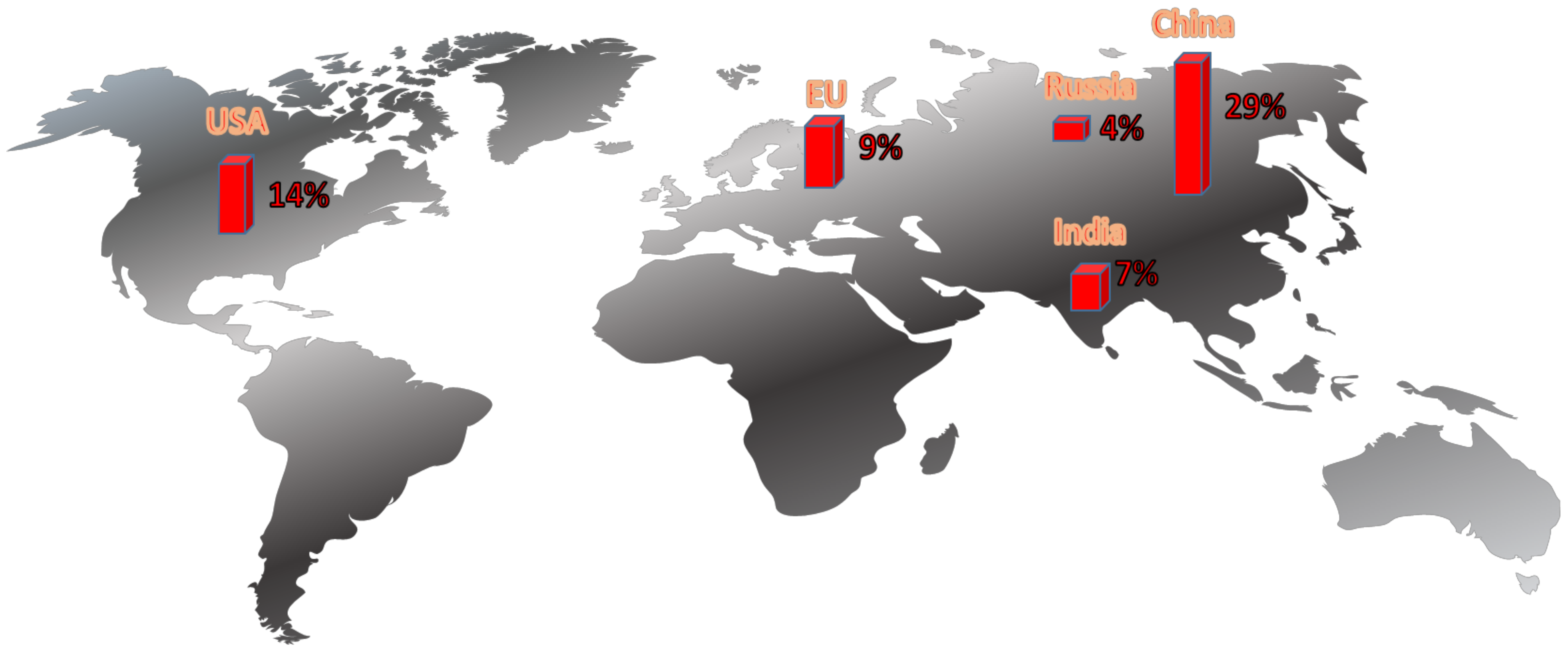
1.1. European and World Regulations Concerning the Reduction of CO2 Emissions

The process of aggressive human exploration of nature over the past millennia has resulted in its irreversible degradation. As early as 1972, based on the published Report of the Club of Rome, the world elites were aware of the depletion of natural resources [13]. For many years, energy was a more important area of study than climate [14,15].
The EU between 1990 and 2018 reduced greenhouse gas emissions by 23% while growing its economy by 61% [16]. Unfortunately, this achievement was achieved by shifting greenhouse gas emissions outside the Union (carbon leakage), which may even have increased emissions due to less advanced production methods in other countries.
In fact, it was not until 2020 that proper action was taken against the mechanism of environmental destruction. In July 2021, the European Commission announced a package of legislative changes (Fit for 55), the implementation of which is to lead to a reduction in the carbon intensity of the economy by at least 55% by 2030 compared to 1990, and ultimately to climate neutrality in 2050. The most important changes concern the taxation of all fossil fuels, the increase to 40% of energy production from renewable sources by 2030, the introduction of limits on car emissions (from 2035, only zero-emission cars can be registered) [17]. In addition, member states such as Poland have introduced internal regulations [18,19].
At the same time, the world’s largest emitters have declared their own environmental undertakings. China declared at the UN General Assembly in 2020 that it would achieve climate neutrality by 2060. The first big step in this direction was the launch of an emissions trading system (ETS). The next must be to increase electricity generation mainly from renewable sources and to combine the burning of fossil fuels with CCS. Without this, China will not be able to achieve its goal [20]. US President Joe Biden, ahead of the April 2021 climate summit, announced an ambitious goal of cutting greenhouse gas emissions in half by 2030 through complete decarbonization of the United States and achieving climate neutrality by 2050 [21,22]. In 2019, Russia joined the Paris Agreement and committed to reducing greenhouse gas emissions by 25–30% from 1990 levels by 2030. The Russian government is currently developing a plan to achieve climate neutrality [23]. India at the COP26 climate summit announced its desire to achieve climate neutrality by 2070, while asking for a hefty bailout of at least one trillion USD to deliver on its promises [24]. Figure 1 shows the highest percentages of carbon dioxide emissions.
The progressive decarbonization and increasing share of CE in the global economy is a long-term process, planned for the next decades, during which the CO2 produced from coal-fired power generation will still be a serious threat. The only right solution at the moment seems to be CO2 capture and storage and/or utilization. Carbon dioxide capture, storage, or disposal (CCS—carbon capture and storage/CCU—carbon capture and utilization) are the only realistic options for reducing emissions of pollutants into the atmosphere. Figure 2 shows the relationship between the main technologies aimed at reducing the amount of carbon dioxide. The emphasis is placed on the development of technologies conducive to the capture of CO2 from the combustion of fossil fuels, as they constitute the most expensive stage of the CCS process.
The basic concept of CCS is the capture of emitted CO2 by large high-density sources such as power plants, followed by sequestration or storage. CCS is a multistage process; in the first stage, carbon dioxide is captured, and then compressed for easier transport to a storage site [26]. The transport is achieved by pipeline or other means of transport [27]. The last stage can take different forms of the CO2 pathway; if it is stored, observations are made of the ground layer under which the carbon dioxide is stored. It can be stored in the ground or in the deep sea [28,29]. The dissimilarity of CCU technology with CCS technology is associated with change in the final process step from storage to carbon dioxide utilization. During this process, the captured and transported CO2 can be used in processes where it becomes a substrate again. It is needed in processes such as the production of concrete, plastics, or biofuels [30]. The shift from CCS to CCU is leading to a shift in the perception of CO2, which becomes not only waste, but also a resource that is useful in many industries, a clear example of the transition from a linear economy to a circular economy [31].
There is a question of applying appropriate methods and materials to capture carbon dioxide and transfer it to the processes where it will be a substrate. Waste appears to be such a material. When properly treated, it can become an adsorbent of carbon dioxide.

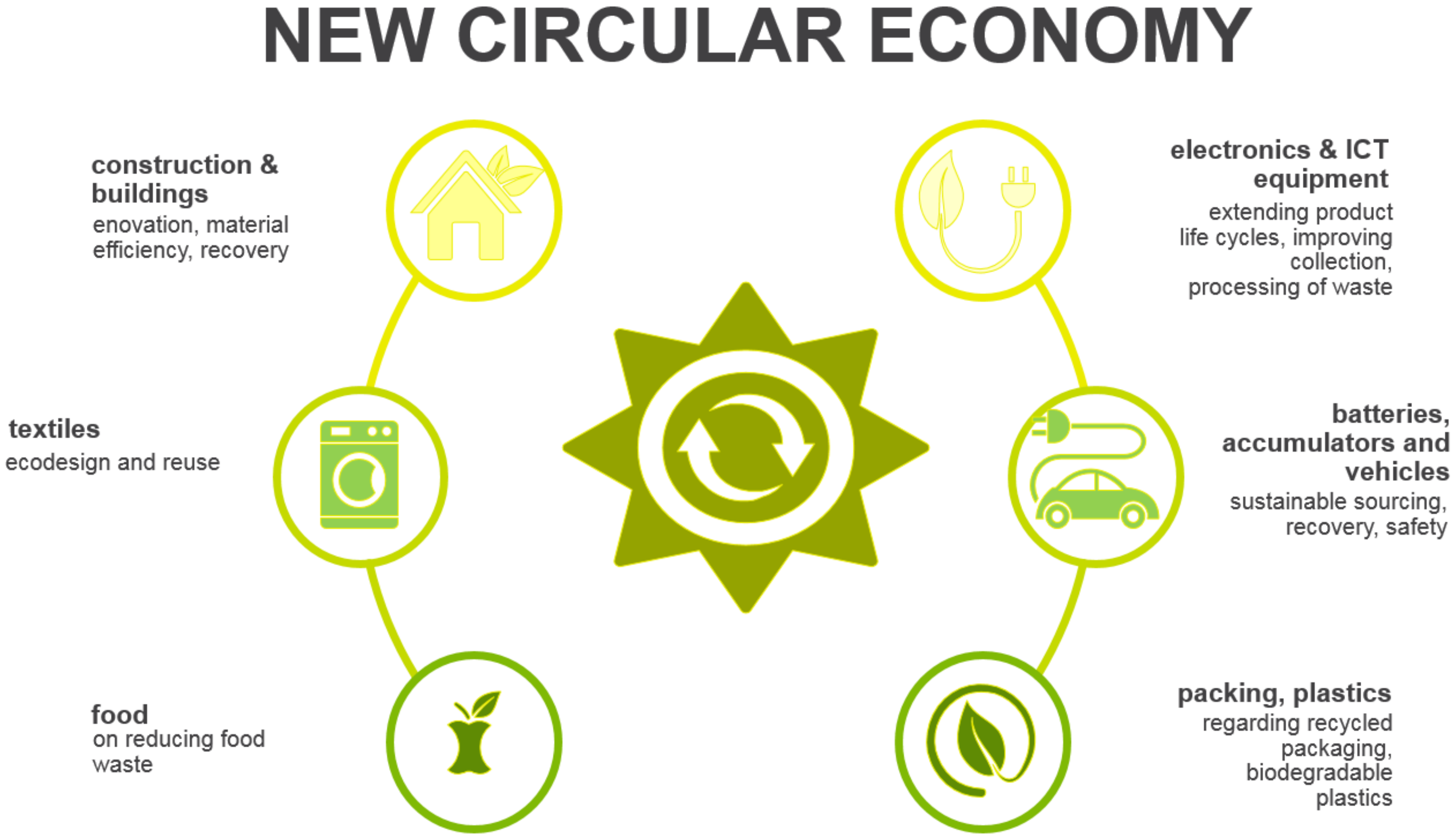
1.2. Bio-Waste in a Circular Economy

Waste and its associated hazards are a serious problem in environmental protection. The main cause of excessive waste is irrational resource management. Currently, more than two billion tons of waste is produced worldwide each year [32]. EU residents produce an average of seven tons of waste per capita (as of 2018). More than half of the waste generated in the EU was recycled which means that unfortunately more than 45% remained landfilled or incinerated without energy recovery [33].
The closed-loop economy is a model that enables the rational use of natural resources reducing or eliminating the negative environmental impacts of products and processes.
In recent years, the closed loop economy has been a priority in the economic policy of the Union. Further actions are planned and implemented, including the “New EU Action Plan on the Closed Cycle Economy for a Cleaner and More Competitive Europe” the main principles of which are shown in Figure 3 [34].
The new action plan assumes the production of more durable and sustainable products. It encourages a product–service system in which the entrepreneur retains responsibility for the product and its life cycle. Disposable products, on the other hand, will be phased out of the market whenever possible and replaced by durable and reusable products.
Municipal waste is waste generated in households and infrastructure facilities. The amount and morphological composition of municipal waste largely depend on the place where it is generated. The collection and disposal of waste is relatively correct, while the more difficult task to solve is the recovery or neutralization of waste, such that the landfilling of waste does not constitute such a large share in the waste management [35,36].
Storage of waste means additional gas emissions to the atmosphere, along with the risk of contamination of surface and subcutaneous waters, contamination of the surrounding areas with blown dust and light fraction waste, or excessive development of birds and rodents [37,38].
The use of waste as secondary raw materials, in addition to eliminating environmental pollution, allows for new economic effects by increasing the base of raw materials, reducing the capital and energy consumption of obtaining and processing raw materials, and reducing the consumption of materials and production costs [39].
The basic element in a rational economic system must be selective collection and segregation of waste, which will enable its further processing [37]. Substantial waste still remains landfilled; hence, it is important to look for ways to manage it. One of such solutions in recent years seems to be the possibility of processing waste from the remains of food consumed by humans to produce among other adsorbents.
Adsorbents are the most popular components of the technology for separation and capture of carbon dioxide from flue gases. Their differentiation is due in part to the method of capture used, the characteristics of which can be found in the next section.

2. Methods of CO2 Capture with Solid Sorbents

The possibility of reducing carbon dioxide emissions from the power sector will be possible with the simultaneous application of several methodological solutions [40]: (1) reducing the combustion of fossil fuels by reducing the consumption of energy generated from coal for the production of energy from renewable or nuclear energy; (2) improving the efficiency of coal-fired power plants by modernizing installations and installing filtration units; (3) carbon dioxide capture and storage, which is becoming an ideal method to meet the needs of today’s energy economy, taking into account the possibility of not only CO2 storage, but also reuse of the oil extraction process or industry.
There are three carbon dioxide capture systems: pre-combustion, oxy-combustion, and post-combustion. The technology of pre-combustion in the first stage leads to fuel gasification, then catalytic hydrogenation of the gas to produce CO2, which is captured in the chemical process, and physical absorption [41]. The process of oxygen combustion consists in recirculation of exhaust gases in the air enriched with oxygen [42]. The resulting gases are saturated with CO2 and water vapor [43]. The most popular method seems to be capturing carbon dioxide after combustion, thanks to its wide application [40]. It takes place by separating CO2 from the gas mixture after combustion. Several techniques of carbon dioxide capture are known: absorption, adsorption [44], membrane separation, cryogenic method [45], and biofixation with microalgae [46].
Post-combustion capture technology has several advantages that set it above other CO2 capture and sequestration techniques. The possibility of retrofitting a power plant with a CO2 capture installation is easier in this method, due to the retrofitting of a power plant with an element that will remove carbon dioxide after the combustion process, without interfering with the power plant infrastructure. Most of the capture techniques for this method are commercially available, while others have proven themselves on a smaller scale. There also remains operational flexibility to allow the use of optional CO2 capture [47].

2.1. Post-Combustion

The arguments presented above are behind the choice of technology after the combustion process. There is great progress visible in the development of this method, along with wide interest and a need for its use. In Norway, the Technology Center Mongstad has been operating a carbon dioxide capture installation after combustion since 2012. It is capable of capturing 100,000 tons of CO2 annually [48]. A similar installation is also located in Canada, the SaskPower CCS Facility, which captured almost 8,000,000 tons of CO2 in 2020 [49]. As already presented, the process of carbon dioxide capture itself can be carried out using the following methods: adsorption, absorption, cryogenic, and membrane [50].
So far, the most developed process of CO2 capture is chemical absorption, although, due to its costly nature, efforts are being made to develop other methods [51].
Below, pre-combustion technologies based on absorption methods are discussed.
There are methods of CO2 capture from flue gas, based on adsorption processes [52]. Adsorption processes differ from absorption processes in their ability to bind molecules. The process takes place only on the surface of the adsorbent. Due to the mechanism of binding particles, we distinguish between physical and chemical adsorption.
Physical adsorption is based on the formation of weak hydrogen bonds and van der Waals interactions between the sorbent and adsorbate particles, enabling multilayer coverage of the adsorbent. Chemical adsorption binds the particles to the surface of the sorbent by exchanging an electron charge, creating a monolayer on the surface of the adsorbent. Binding the particles only at the sorbent surface without interfering with its internal structure will facilitate the particle desorption process. This property is a great advantage for the sorbent regeneration process [53].
The different types of adsorption process are presented below.
Pressure swing adsorption (PSA) is based on the phenomenon of selective adsorption of gases on solid adsorbents [54]. In subsequent sorption/desorption cycles, the pressure increases and decreases, respectively. In addition to the best-known method of pressure swing adsorption, there are other types that differ in the desorption processes carried out.
Thermal swing adsorption (TSA) is carried out by increasing the temperature of the adsorbent, heated by a gas stream in the exchanger. The advantage of this method is high efficiency and speed of the process, but the need to cool the system in the final phase extends the work [55].
Pressure temperature swing adsorption (PTSA) is a combination of the two previously discussed methods. The combination of increased pressure during gas sorption and high temperature in the sorbent regeneration cycle shows significant benefits for the overall process [56].
Electric swing adsorption (ESA) is possible due to the differentiation of the electrical supply in these alternating processes. The process is similar in functionality to TSA due to the temperature increase at the time of desorption of the ingredient. However, in this process, the increase in the bed temperature occurs due to the supply of energy in an electric way [57].
Vacuum swing adsorption (VSA) or vacuum pressure swing adsorption (VPSA) is carried out under negative pressure, enabling adsorption under atmospheric pressure [58].
Fast and ultrafast pressure swing adsorption, rapid pressure swing adsorption (RPSA), and ultra-rapid pressure swing adsorption (URPSA) represent further alternatives [59].
Shuttle adsorption (PVSA) is distinguished by its simplicity and low energy demand. The adsorption technology is based on increasing the pressure and creating a vacuum in the desorption process [60,61,62].
The most frequently used adsorption process is the pressure swing adsorption process (PSA). It has been modified to use variable temperature or variable vacuum (TSA or VSA) [58,59,61].
Materials used in adsorption processes must have classified features. They should be characterized by a high specific surface, large pore volume, regenerability, high chemical stability, non-hygroscopicity, and resistance to changes in conditions. Recyclability is an additional welcome feature. The materials commonly used in carbon dioxide adsorption processes are zeolites [63], metal–organic frameworks [64,65], amine-functionalized silica [66], and porous carbons [67,68,69]. The materials that enjoy great success in their use in adsorption methods are solid sorbents, connected with easier methods of modifying their structures, transport, and use.

2.2. Solid Sorbents Used in CO2 Capture

Carbon dioxide capture processes are based on the possibility of interaction between the solid adsorbent and the absorbed gas molecule [70]. Dry adsorbents must have important variables in the dry adsorption process. The most important feature of sorption materials is porosity and surface tension. For this reason, a large area of research is devoted solely to the possibility of modifying the porous structure of adsorbents. In this regard, tests were carried out on favorable conditions enabling the selective absorption of CO2 from the gas mixture. Accordingly, they feature favorable pores with a size of 0.7–0.9 nm, corresponding to twice the diameter of the CO2 particle, for the adsorption of this component [71].
However, it is almost impossible to obtain monodisperse material containing only such pores. At the same time, the improvement of laboratory methods contributes to the increase in and control of the pore size. The most monodisperse particles have been achieved for biochar. These materials are the most environmentally friendly, as they are made of waste materials, thus reducing waste. In addition, their susceptibility to modification makes it possible to adjust their properties to almost any type of substance that would be adsorbed.
The surface of the porous structure affects the performance of the material used for adsorption. A more developed structure in a smaller space represents greater efficiency.
Due to the exhaust gas outlet conditions mentioned in the introduction in the energy industry, the adsorbents are expected to be capable of capturing carbon dioxide at low pressure.
From an economic point of view, the cost of producing the adsorbent materials plays a key role.
Recently, waste substrates have become very popular, with their reuse for the production of adsorbents representing an innovative idea. This use of waste, by putting it back into circulation, makes it possible to implement the concept of a circular economy. These materials are safe for the environment, as they enable a reduction in the carbon footprint of waste by recycling it instead of depositing it in landfills. The characteristics of biowaste and the production process to form bioadsorbents are presented in the next section.
Table 1 characterizes popular adsorbents used to capture carbon dioxide.

3. Production of Adsorbents Based on Bio-Waste

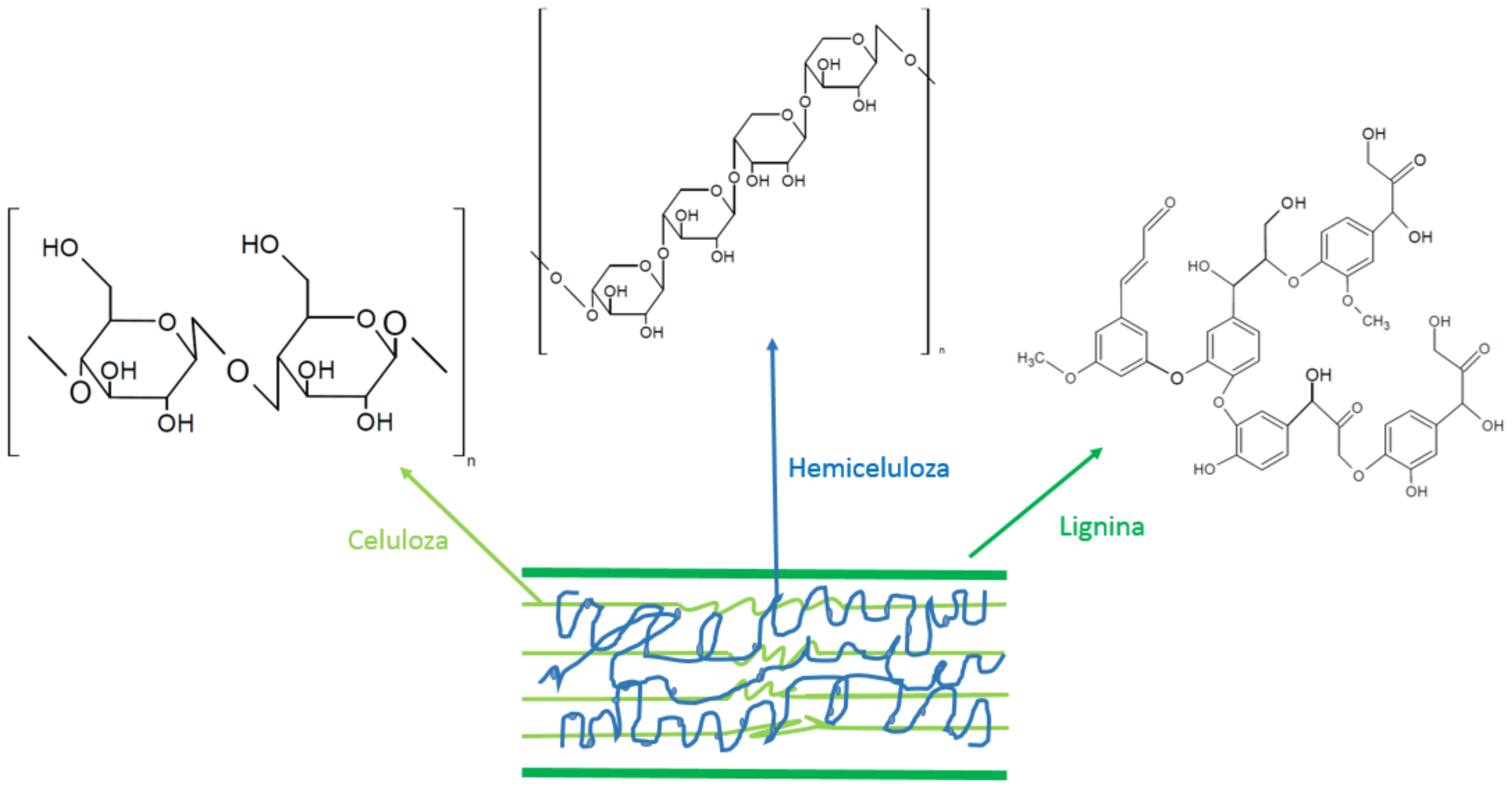
3.1. Characteristics of Bio-Waste

Plant biomass consists of three basic components: lignin, cellulose, and hemicellulose. The percentage of lignin in plant materials ranges from 15% to 25%, while cellulose can be as high as 50%, and hemicellulose constitutes 23–32% [72].
The most famous and valued element of biomass is cellulose, which has been used as a production material for centuries to make paper. Due to the growing awareness of the need to use the available resources of nature as a whole, the remaining elements of biomass were interfered with, i.e., lignin and hemicellulose, which were simply burned during the production of paper.
Lignin is a natural polymer that surrounds the cellulose fibers (Figure 4). It is insoluble, and, due to the presence of bonds of aldehyde and carbonyl groups, it is a strong polarized structure, which in most cases is the backbone for materials transformed into the form of sorbents. However, Ukanwa et al. found that the chemical activation process dissolves lignin better than cellulose, causing higher volatility, dustiness, and brittleness of the materials obtained via this process [73].
Most often, however, during carbonization and activation, volatile substances are removed from cellulose and hemicellulose. The two elements are similar, with the only difference in their structure being the number of saccharides.
Lignin participates in thermochemical transformations across a wide range of temperatures, from 150 °C to 900 °C; the main transformations of cellulose, in contrast, are at temperatures from 325 °C to 375 °C, while those of hemicellulose range from 225 °C to 325 °C [74]. Significant changes in the structure of the obtained products can be seen after exceeding 25 °C. This is related to the commencement of hemicellulose transformation processes.
Cellulose is a macromolecule made of repeating units of β-D-glucopyranose linked together by bonds. It does not undergo the process of hydrolysis; it is acted on by strong alkaline or oxidizing agents [75]. The ordered structure of hydrogen bonds gives rise to its physical properties.
Hemicellulose as a nonhomogeneous structure, whose chains are accumulated with high sugars. In contrast to cellulose, it undergoes hydrolysis, as determined by its lower weight than cellulose [76].
An important property of plant biomass is its content of mineral substances. The elements in the composition of the mineral substance are silicon, calcium, potassium, sodium, and magnesium, as well as sulfur, phosphorus, iron, manganese, and aluminum in smaller amounts. The chemical composition of biomass is important when choosing an installation or biomass conversion technology, due to the corrosive properties of some elements. Moreover, the high percentage of elements other than carbon in the biomass proves the low efficiency of the biomass to biochar conversion processes. It can lead to a different pH of the obtained biochar, which negatively affects the carbon dioxide capture system.
The content of individual elements in the structure of biomass affects their consumption after the processes of maintaining bioadsorbents, which is visible in their physicochemical properties.

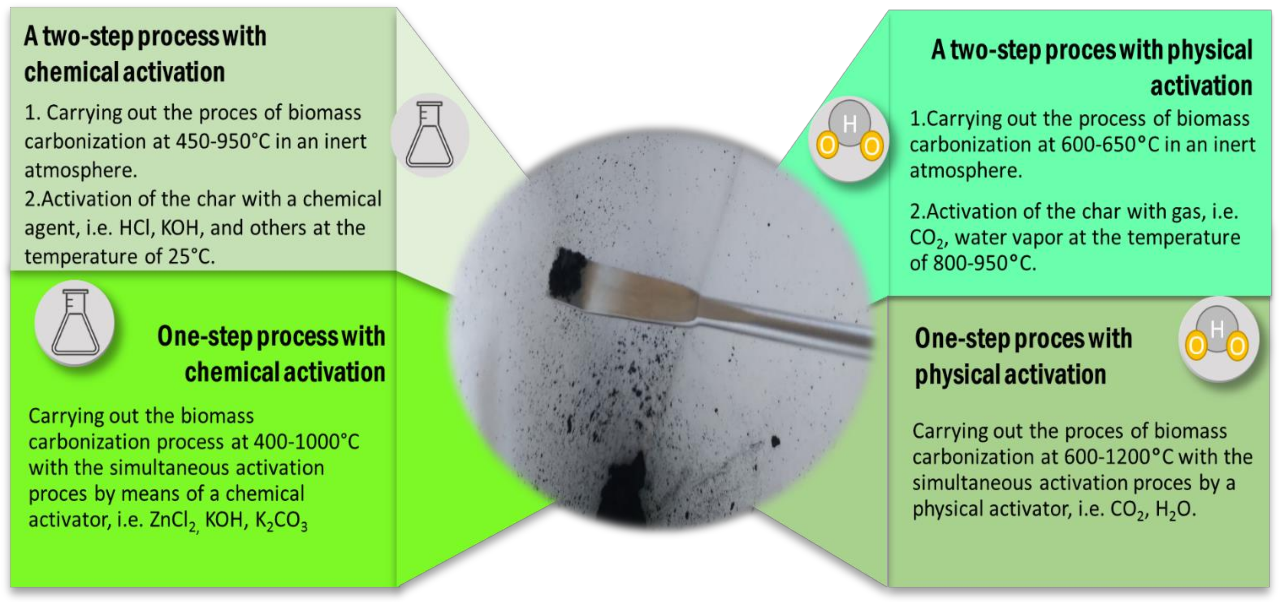
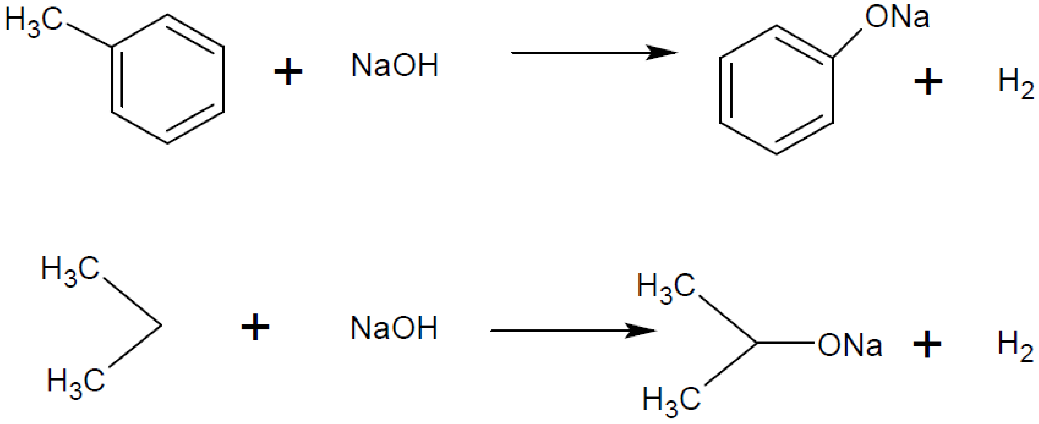
3.2. Production Process of Bioadsorbents

The characteristic processes of thermochemical conversion in order to obtain biocarbon or the appropriate product/bioadsorbent are torrefaction and pyrolysis/carbonization.
Torrefaction, also called initial pyrolysis, is carried out in anaerobic conditions in the range of low temperatures for the combustion process ranging from 200 to 300 °C. The temperature increase per minute should not exceed 50 °C, and the residence time in the combustion chamber should not exceed 1 h. After this process, the product should be characterized by a higher percentage of C and lower humidity. Table 2 contains the impact of torrefaction parameters on the content of the main elements.
In the pyrolysis process, which involves thermal decomposition of the substrate under anaerobic conditions, three groups of products are obtained: gas, liquid, and solid (biochar).
The pyrolysis process can be classified. Conventional pyrolysis, carried out under atmospheric pressure with a low temperature rise, is characterized by the formation of a highly carbonated solid product, which is highly desirable when it comes to bioadsorbents, despite converting only about 30% of the input material [82]. Fast and instant pyrolysis is characterized by an average and short residence time in the boiler with a rapid increase in temperature. The main product is liquid (bio-oil), representing 50% to 75% of the total [83,84].
We also distinguish hydrothermal processes, which include hydrothermal carbonization (HTC) and hydrothermal liquefaction (HTL). The HTC process is carried out over 3 to even 72 h, at temperatures of 180–260 °C. The process medium is water in the form of saturated steam. It also acts as a catalyst and heat carrier [85]. Biomass components under the influence of water under subcritical conditions are subject to hydrolysis. The product is largely dehydrated by dehydration and decarboxylation. The amount of water added to the reaction process is of great importance here. Minor variations in concentrations can lead to a significant drop in yield. A significant advantage of these methods is that there is no need to dry the batch material, whereas the disadvantage is the cost of an installation resistant to subcritical water conditions. Controlling the process conditions leads to obtaining products of different composition. In the HTC process, the main product is a solid product in the form of carbon [86,87].
The HTL process is carried out under increased pressure, and its main product is bio-oil. The selection of the process duration, temperature, and pressure, and use of catalysts affect the composition of the products [88].
Both physical and chemical activation processes are aimed at increasing the porous surface of bioadsorbents, thus increasing the adsorption efficiency.
The currently used activation methods overlap with the methods of biochar production in pyrolytic processes, as shown in Figure 5.
Two-stage physical activation is aimed at developing the specific surface of the already carbonized material with the help of an inert gas. One-step activation is the reaction of simultaneous combustion of the carbon substrate and increasing its surface porosity. Steam, air, oxygen, carbon dioxide, or mixtures thereof are used as the inert gas. The use of air or oxygen may be risky due to the possibility of ignition [89].
The lower temperature of the process enables the use of two-stage methods, whereas too high temperatures reduce the efficiency of the process, leading to the collapse of the porous structure and the generation of ash. Physical activation is environmentally safe, but speed and temperature requirements are problematic [90].
Chemical activation is carried out in the process of inert gas, e.g., nitrogen or argon. The following chemicals are used as activating factors: inorganic acids (H3PO4, HNO3, H2SO4), hydroxides (KOH, NaOH), or K3PO4 and ZnCl2 salts. An example of a compound structure modification reaction is shown in Figure 6. Recent studies favor the use of KOH as a factor due to the highly microporous structure obtained with a narrow pore range [91]. The activating agent used is most often removed in the rinsing process until the pH is neutral.

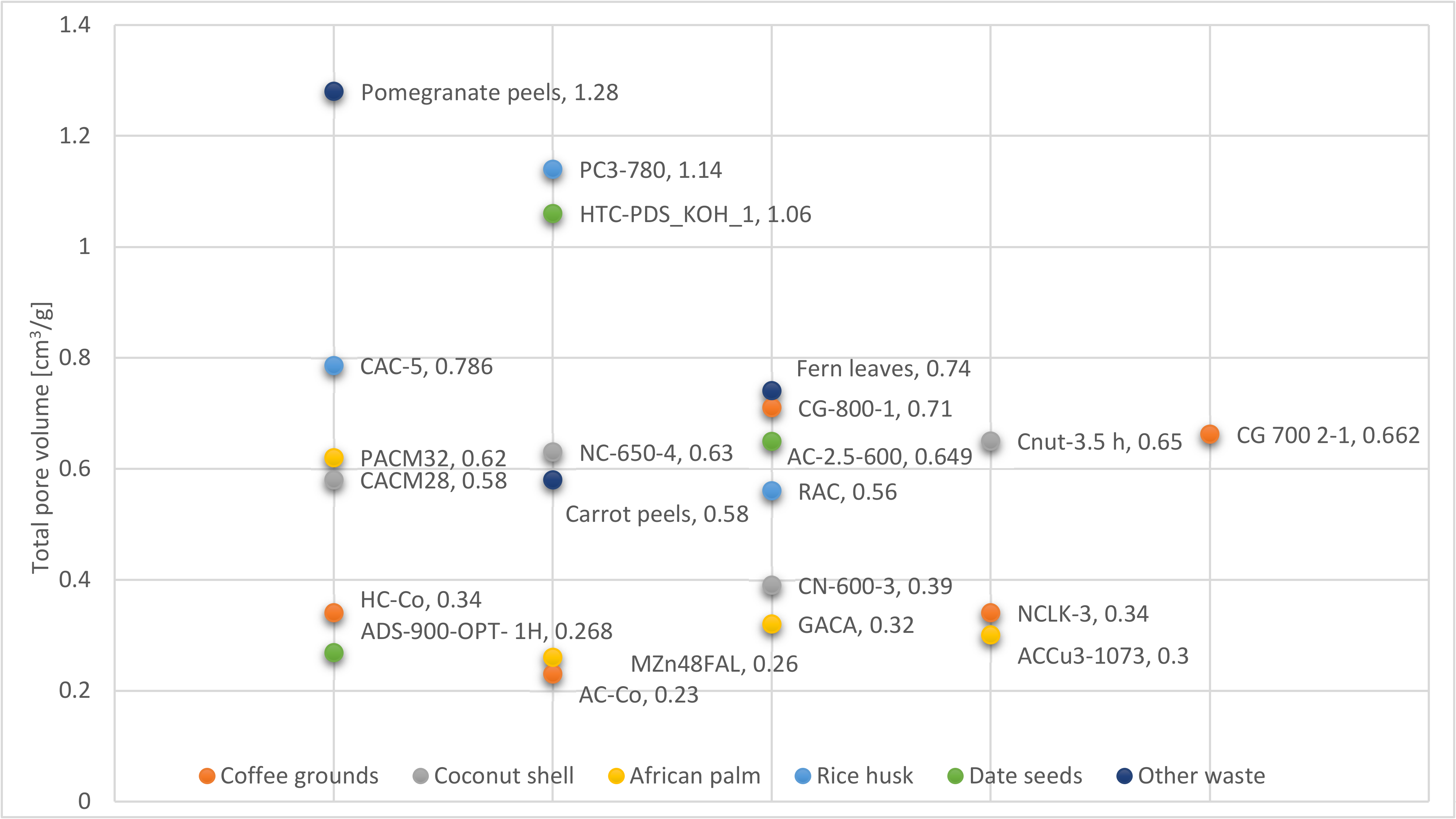
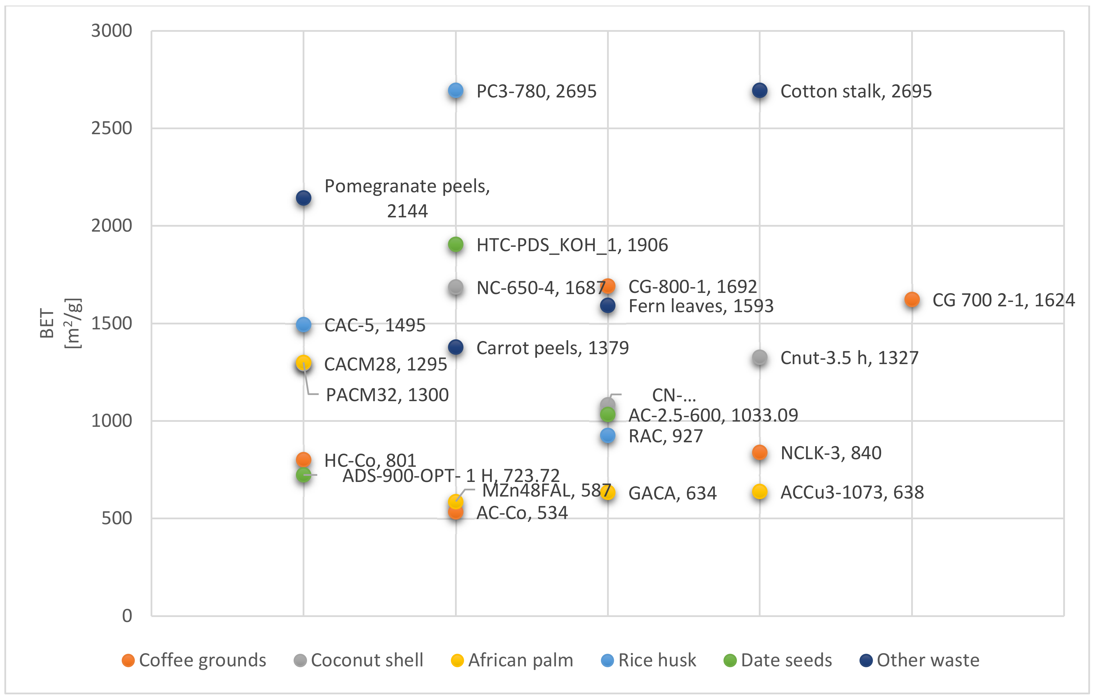
4. Characteristics of Bioadsorbents Obtained on the Basis of Bio-Waste

During the literature review, bioadsorbents prepared from the most commonly used bio-waste for this purpose were selected. The materials readily available in the areas inhabited by the authors are very popular among scientists. The popularity of selected bio-waste is also growing. Interestingly, the interest in individual materials has changed over the past decade.
In the last few years, there has been a noticeable increase in the interest in various bio-waste. Literature data on these materials were collected, and they are classified in Table 3.
Coffee grounds have become a breakthrough material used in many areas of life. Scientists also often use the advantages of this raw material. A literature review revealed the diversity of the applied modification processes through physical and chemical activation.
Many scientific papers describing carbon dioxide sinks are based on raw materials from coconut shell and African palm trees, and these materials are used consistently, mainly chemically modified.
Rice husk is often used in the production of biochar to adsorb carbon dioxide. Interestingly, carbonized rice husk is a source of high amounts of silica. For this reason, this material is commonly used in the production of other types of carbon dioxide adsorbents in the form of nanocomposites. Currently, rice husk processed in this way into nanocomposites is now more and more often used in the processes of carbon dioxide adsorption.
The last rows of Table 3 gather data on bioadsorbents produced from various types of waste that have been gaining popularity in recent years such as vegetable peelings, leaves, or plant stems.
The production of bioadsorbents through physical activation of the collected materials was carried out in one or two stages. Activation of carbon materials with CO2 is gaining attention due to the ability to produce ultra-micropores suitable for CO2 adsorption.
Comparing the method of activating materials in most products, chemical activation dominates with solid activators, which can be seen in Table 3. The most frequently chosen chemical activator is potassium hydroxide, followed by orthophosphoric acid and zinc chloride.
The materials can be activated in one, two, or even three steps. Chemical activation can be accomplished via two methods, wet impregnation and solid–solid mixing. In the wet impregnation method, the raw biomass or raw material is first mixed with the activator in the appropriate proportion to prepare the slurry.
The prepared suspension is carbonized or activated under inert conditions to obtain chemically activated carbon. In dry activation, the precursor is mixed with the activator using a stirrer or in a mortar. The mixture is then converted to activated carbon in a heat treatment process in which both processes (carbonization and activation) occur simultaneously. Additionally, the activation and carbonization processes are used interchangeably. There is no established pattern to support that pre-activation carbonization gives better results than pre-carbonization activation.
Querejeta et al. obtained bioadsorbents from coffee grounds via single- and two-step physical activation with better results for single-step activation and lower temperature (3.01 and 2.71 mmol/g CO2, respectively), at 50 °C and 10 kPa pressure. The highest result of adsorption at 25 °C and at atmospheric pressure, 5.44 mmol/g, was obtained for the HTC-PDS_KOH_1 sample activated physically with CO2 and KOH [108].
KOH as an activator allows obtaining a typically microporous structure. Chen et al. produced the NC-650-4 bioadsorbent enriched with urea and then activated KOH with an area of 1687 m2/g and an adsorption capacity of 7 mmol/g at 0 and 1 atm [97]. The highest carbon dioxide adsorption was also obtained for the product activated with KOH. It was 7.55 mmol/g and 4.42 mmol/g at 0 and 25 °C and 1 atm, respectively, for the CG 700 2-1 sample in the research group of Travis et al. [95]. The adsorption capacity of the bioadsorbents is presented in Table 4.
Despite the good activating properties, the use of KOH also has some limitations. Because KOH is strong dehydrating agent, it has corrosive properties. The corrosivity increases with increasing activation temperature, making it disadvantageous for large-scale and industrial production application [113]. Moreover, after rinsing the bioadsorbents, environmental pollutants are created. Therefore, the focus should be on finding and using activators or activation methods that are more environmentally friendly and less corrosive.
The use of K2CO3 in the activation of coconut shells and coffee grounds gave high results of adsorption efficiency of 7.18 mmol/g and 5.12 mmol/g, respectively, at 0 °C and 1 atm pressure. Additionally, the bioadsorbent with higher sorption capacity was enriched with urea [93,98].
Conducting carbon dioxide adsorption tests to reflect target conditions should be performed at 30 °C and atmospheric pressure. These conditions assume no additional costs associated with the preparation of flue gases for purification. In addition to the assumed most favorable conditions, the authors carried out tests at reduced pressure and higher or lower temperature (summary Table 4). Analysis of carbon dioxide adsorption under different conditions allows a comparison of adsorption efficiency and possible modification of adsorption conditions by heating/cooling the flue gas and crowding if this allows a significant increase in adsorption processes. As can be seen from the summary in Table 4, the best results for the compared bioadsorbents were obtained at 0 °C under atmospheric pressure. For coffee bioadsorbents CG800-1/CG 700 2-1 and rice husk CAC-5/PC3-780, lowering the temperature resulted in a 40% increase in carbon dioxide sorption [93,95,103,104]. For sorbents prepared from coconut shells and other wastes, whose data were collected in this review, for which tests were conducted at two temperatures (0 and 30 °C), the carbon dioxide sorption at the lower temperature increased by 30% [97,98,99,110,111,112].
Table 5 shows a compositional analysis of the collected raw materials, which were used for the production of adsorptive materials by the various authors. The precursors used in the production of adsorbents should have a low ash content. Research has shown that too much ash may hinder the development of pores during further processing of the material [114].
The influence of the elemental composition on the adsorption capacity of the characterized bioadsorbents is significant. We can see the dependence of the increasing percentage of carbon, which coincides with the differing efficiency in the adsorption process shown in Table 4 and Table 5. The exception to this rule is the GACA bioadsorbent obtained by Giraldo et al., where a significantly smaller amount of carbon in the composition of the bioadsorbent led to carbon dioxide adsorption results of 7.53 mmol/g of the sample at 0 °C and atmospheric pressure [101].
In addition, it should be emphasized that, in most cases, tests of sorbent regeneration with high efficiency were carried out by the authors. The regeneration processes were caused by the pressure difference between the adsorption and desorption processes. This means that the produced adsorbents are perfect for cyclical operation in carbon dioxide absorption installations.
Chemical activation is the use of an activating agent. Its task is to develop the porous structure of the final product by preventing the production of byproducts such as tar or volatile compounds.
The pore volume, specific surface area, carbon properties, and yield of the bioadsorbents are dependent on the maximum feed/activating agent ratio, carbonization temperature, heating rate, and activation time. Bioadsorbents produced by chemical activation have a very high specific surface area, in the range of 2000–3000 m2/g [104,110,112].
The specific surface is the ratio of the internal surface area of the pores contained in a sample of a porous material to the volume of this sample. The specific surface is an important feature of permeable porous materials, because it determines the course of those processes for which the pore surface development is of fundamental importance.
The total pore volume is the sum of the open and closed pores. Figure 7 and Figure 8 characterize the distribution of these values for the bioadsorbents collected in the article. The authors used a volumetric adsorption analyzer to determine the surface area and porosity of the obtained materials. When comparing these values for individual bioadsorbents, we can see size differences for the same samples. This is due to the fact that the pore volume often does not reflect its surface area and vice versa. However, the samples in both plots were largely in a similar distribution when comparing the total pore volume and the specific surface area. Therefore, it is important to determine both of these values for the samples in order to fully characterize them.
Comparing the obtained adsorption values of the bioadsorbents obtained by the authors with the specific surface of the samples and their volumes, we can see that the samples with the highest Vt and BET values did not obtain the highest carbon dioxide adsorption results.
This is related to the specificity of matching the pore size of the sample to the particle absorbed in the adsorption process.
In addition, closed pores, included in the BET and Vt (total pore volume) characteristics, prevent the absorption of external particles.

5. Conclusions and Prospects for Application of Bioadsorbents in CO2 Capture

The use of bio-waste as a CO2 adsorbent is a cost-effective and prosperous idea. The management of some waste can extend the circular economy package. At the same time, its use in the adsorption of carbon dioxide will help to combat the problem of excessive CO2 emissions. The presented bio-waste used in the production of bioadsorbents appears to be a good material for carbon dioxide separation and capture.
An efficient carbon dioxide adsorbent consists of many properties, including the specific surface area and the volume of micropores. Therefore, an inherent element in the production of bioadsorbents is their activation by modifying the surface, which will allow more carbon dioxide to be adsorbed.
To the greatest extent, the process of activation and surface modification affects the efficiency of the resulting adsorbent material. A large number of micropores and a high specific surface area are the characteristics of a good, effective carbon dioxide sorbent. Keeping the specific surface area within 2000 m2/g after carbon dioxide sorption is a key condition for the efficiency of the obtained adsorbents, indicating that the best way of activation is surface modification through a chemical activator. The results obtained, albeit converging, favor potassium hydroxide. For the most part, materials obtained using two- and three-step processes received better results.
The authors did not consider the complexity of the activation process due to the use of often several surface activators. This activation process makes it difficult and costly, with a negative impact on the environment. The results obtained from a more complicated activation process are comparable to physical adsorption or one activator.
The high efficiency of the adsorption process obtained at 0 °C and 25 °C gives hope for facilitating the sorption process without modifying the exhaust gas temperature. On the other hand, the high regenerative capacity and long cyclicality of the adsorbents reduce the costs and high energy levels of adsorbent preparation in pyrolytic and activation processes.
However, little research has been conducted on the large-scale production and use of modified biochar for CO2 capture. Therefore, further research should focus on large-scale production of bioadsorbents. A second aspect of research development should be technologies aimed at the regeneration of bioadsorbents and the use of captured carbon dioxide.

Author Contributions

Conceptualization, M.S. and I.M.-K.; investigation, M.S., I.M.-K. and D.W.; methodology, M.S.; writing—original draft preparation, M.S.; writing—review and editing, M.S. and I.M.-K. All authors have read and agreed to the published version of the manuscript.

Funding

This article has been supported by the Polish National Agency for Academic Exchange under Grant No. PPI/APM/2019/1/00042/U/00001. The scientific research was funded by the statute subvention of Czestochowa University of Technology, Faculty of Infrastructure and Environment.

Data Availability Statement

Not applicable.

Conflicts of Interest

The authors declare no conflict of interest.

References

  1. North, M. What is CO2? Thermodynamics, basic reactions and physical chemistry. In Carbon Dioxide Utilisation; Elsevier: Amsterdam, The Netherlands, 2015; pp. 3–17. [Google Scholar]
  2. The Royal Society. Climate Change: A Summary of the Science; The Royal Society: London, UK, 2010; Volume 4, p. 2. [Google Scholar]
  3. Liu, Z. National carbon emissions from the industry process: Production of glass, soda ash, ammonia, calcium carbide and alumina. Appl. Energy 2016, 166, 239–244. [Google Scholar] [CrossRef]
  4. EPA. Inventory of Greenhouse Gas Emissions and Sinks 1990–2017; EPA: Washington, DC, USA, 2019; p. 657.
  5. Ziobrowski, Z.; Rotkegel, A. Comparison of CO2 Separation Efficiency from Flue Gases Based on Commonly Used Methods and Materials. Materials 2022, 15, 460. [Google Scholar] [CrossRef] [PubMed]
  6. Ali, U.; Font-Palma, C.; Akram, M.; Agbonghae, E.O.; Ingham, D.B.; Pourkashanian, M. Comparative potential of natural gas, coal and biomass fired power plant with post-combustion CO2 capture and compression. Int. J. Greenh. Gas Control 2017, 63, 184–193. [Google Scholar] [CrossRef]
  7. Uliasz-Bocheńczyk, A.; Mokrzycki, E. Przegląd możliwości utylizacji ditlenku węgla. Wiert. Naft. Gaz 2005, 22, 373–378. [Google Scholar]
  8. Davison, J. Performance and costs of power plants with capture and storage of CO2. Energy 2007, 32, 1163–1176. [Google Scholar] [CrossRef]
  9. Atlaskin, A.A.; Kryuchkov, S.S.; Yanbikov, N.R.; Smorodin, K.A.; Petukhov, A.N.; Trubyanov, M.M.; Vorotyntsev, V.M.; Vorotyntsev, I.V. Comprehensive experimental study of acid gases removal process by membrane-assisted gas absorption using imidazolium ionic liquids solutions absorbent. Sep. Purif. Technol. 2020, 239, 116578. [Google Scholar] [CrossRef]
  10. Gulzar, A.; Gulzar, A.; Ansari, M.B.; He, F.; Gai, S.; Yang, P. Carbon dioxide utilization: A paradigm shift with CO2 economy. Chem. Eng. J. Adv. 2020, 3, 100013. [Google Scholar] [CrossRef]
  11. Reza, M.S.; Yun, C.S.; Afroze, S.; Radenahmad, N.; Bakar, M.S.A.; Saidur, R.; Taweekun, J.; Azad, A.K. Preparation of activated carbon from biomass and its’ applications in water and gas purification, a review. Arab J. Basic Appl. Sci. 2020, 27, 208–238. [Google Scholar] [CrossRef]
  12. Ogungbenro, A.E.; Quang, D.V.; Al-Ali, K.A.; Vega, L.F.; Abu-Zahra, M.R. Synthesis and characterization of activated carbon from biomass date seeds for carbon dioxide adsorption. J. Environ. Chem. Eng. 2020, 8, 104257. [Google Scholar] [CrossRef]
  13. Ramage, M.; Shipp, K. Donella Meadows. In Systems Thinkers; Treaty establishing the European Coal and Steel Community; Springer: London, UK, 2020; pp. 107–117. [Google Scholar]
  14. Treaty Establishing the European Coal and Steel Community, ECSC Treaty. Available online: https://eur-lex.europa.eu/EN/legal-content/summary/treaty-establishing-the-european-coal-and-steel-community-ecsc-treaty.html (accessed on 5 May 2022).
  15. Consolidated Versions of the Treaty on European Union and the Treaty on the Functioning of the European Union-Official Journal of the European Union. Available online: https://eur-lex.europa.eu/legal (accessed on 5 May 2022).
  16. Komisja Europejska. 2019. Annual Report on European SMEs 2018/2019. Available online: https://op.europa.eu/en/publication-detail/-/publication/cadb8188-35b4-11ea-ba6e-01aa75ed71a1/language-en,s.6 (accessed on 5 May 2022).
  17. Jaeger, C.; Mielke, J.; Schütze, F.; Teitge, J.; Wolf, S. The European Green Deal–More Than Climate Neutrality. Intereconomics 2021, 2, 99–107. [Google Scholar]
  18. Tokarski, S.; Superson-Polowiec, B. Energetyka przemysłowa–miejsce w polityce energetycznej Polski. Nowa Energ. 2021, 1, 26–30. [Google Scholar]
  19. Koczan, M. Poland’s energy security in the process of energy transformation. Actual Probl. Int. Relat. 2021, 1, 37–44. [Google Scholar] [CrossRef]
  20. Mallapaty, S. How China could be carbon neutral by mid-century. Nature 2020, 586, 482–483. [Google Scholar] [CrossRef] [PubMed]
  21. The United States’ Nationally Determined Contribution: Reducing Greenhouse Gases in the United States: A 2030 Emissions Target, Washington, DC, 2021. Available online: https://www4.unfccc.int/sites/ndcstaging/PublishedDocuments/ (accessed on 5 May 2022).
  22. Carbis Bay G7 Summit Communique, 2021. Available online: https://www.whitehouse.gov/briefing-room/statementsreleases/2021/06/13/carbis-bay-g7-summit-communique/ (accessed on 21 April 2022).
  23. Jafari, M.; Botterud, A.; Sakti, A. Decarbonizing power systems: A critical review of the role of energy storage. Renew. Sustain. Energy Rev. 2022, 158, 112077. [Google Scholar] [CrossRef]
  24. Chowdhury, A. Explained: India’s Environmental Issues Behind COP 26 Commitments. Available online: https://news.abplive.com/blog/explained-india-s-environmental-issues-behind-cop-26-commitments-1504155 (accessed on 5 June 2022).
  25. Triollet, R. JRC Annual Report 2021. 2019. Available online: https://publications.jrc.ec.europa.eu/repository/handle/JRC119146 (accessed on 5 May 2022).
  26. Uibu, M.; Siirde, A.; Järvik, O.; Trikkel, A.; Yörük, C.R.; Nurk, G.; Kirsimäe, K.; Hazak, A.; Konist, A. ClimMIT-Climate change mitigation with CCS and CCU technologies. In Proceedings of the 15th Greenhouse Gas Control Technologies Conference, Abu Dhabi, United Arab Emirates, 15–18 March 2021. [Google Scholar]
  27. Knoope, M.M.; Ramírez, A.; Faaij, A.P.C. A state-of-the-art review of techno-economic models predicting the costs of CO2 pipeline transport. Int. J. Greenh. Gas Control 2013, 16, 241–270. [Google Scholar] [CrossRef]
  28. Hellevang, H.; Aapaard, P. Can the long-term potential for carbonatization and safe long-term CO2 storage in sedimentary formations be predicted? Appl. Geochem. 2013, 39, 108–118. [Google Scholar] [CrossRef]
  29. Williams, J.D.O.; Jin, M.; Bentham, M.; Pickup, G.E.; Hannis, S.D.; Mackay, E.J. Modelling carbon dioxide storage within closed structures in the UK Bunter Sandstone Formation. Int. J. Greenh. Gas Control 2013, 18, 38–50. [Google Scholar] [CrossRef]
  30. Majchrzak-Kucęba, I. Redukcja śladu węglowego w technologiach utylizacji CO2. Rynek Energii 2019, 3, 23–29. [Google Scholar]
  31. Tcvetkov, P.; Cherepovitsyn, A.; Fedoseev, S. The changing role of CO2 in the transition to a circular economy: Review of carbon sequestration projects. Sustainability 2019, 11, 5834. [Google Scholar] [CrossRef]
  32. Maalouf, A.; Mavropoulos, A.A. Waste Management Market Snapshot 2014–2019: A Global Analysis of Infrastructure Delivery Progress and The Closure of Dumpsites. Available online: https://www.google.com/url?sa=t&rct=j&q=&esrc=s&source=web&cd=&ved=2ahUKEwiI_omZoqT6AhVo-yoKHTUuA3cQFnoECAcQAQ&url=http%3A%2F%2Fuest.ntua.gr%2Fthessaloniki2021%2Fpdfs%2FTHESSALONIKI_2021_Maalouf_Mavropoulos.pdf&usg=AOvVaw2yY0PI9G_O5lN17qQ2RodJ (accessed on 29 May 2022).
  33. Waste Statistics, Eurostat Statistics Explained. Available online: https://ec.europa.eu/eurostat/statistics-explained/index.php?title=Waste_statistics (accessed on 5 May 2022).
  34. Communication from the Commission to the European Parliament, the Council, the European Economic and Social Committee and the Committee of the Regions. Available online: https://eur-lex.europa.eu/legal-content/PL/TXT/?uri=CELEX%3A52021DC0550 (accessed on 5 May 2022).
  35. Bączyk, Z. Selection of equipment for selective waste collection. In Confectionary Materials on the Subject of Waste Management, Part III,-Waste Segregation-A Way to Reduce the Amount of Landfilled Waste; Kiekrz, P., Ed.; ABRYS: Poznań, Poland, 1995. [Google Scholar]
  36. Piotrowska, H. The Problem of Quality in the Disposal and Neutralization of Municipal Waste, Eco-Problems of Industrial and Municipal Waste Disposal; Investor’s Guide; PROEKO: Łajski, Poland, 1995; Volume 4. [Google Scholar]
  37. Przywarska, R. Improving the Condition of Municipal Waste Management-the Current Task of Polish Municipalities; Investor’s Guide; PROEKO: Łajski, Poland, 1995; Volume 1. [Google Scholar]
  38. Rydzicki, Z. State, Needs and Threats in the Field of Waste Management. In Waste Management at Landfills; Kempa, E.S., Ed.; Arka Konsporcjum s.c.: Poznań, Poland, 1993. [Google Scholar]
  39. Jurasz, F. Economy of Secondary Raw Materials; PWN: Warszawa, Poland, 1989. [Google Scholar]
  40. Clean Air Task Force; Freund, H.; Bauer, J.; Zeiser, T.; Emig, G. Advanced post-combustion CO2 capture. Detailed simulation of transport processes in fixed-beds. Ind. Eng. Chem. Res. 2009, 44, 6423–6434. [Google Scholar] [CrossRef]
  41. Demusiak, G. Otrzymywanie paliwa wodorowego metodą reformowania gazu ziemnego dla ogniw paliwowych małej mocy. Wiert. Naft. Gaz 2012, 10, 661–673. [Google Scholar]
  42. Kotowicz, J.; Janusz, K. Sposoby redukcji emisji CO2 z procesów energetycznych. Rynek Energii 2007, 1, 10–18. [Google Scholar]
  43. Gautier, F.; Châtel-Pélage, F.; Varagani, R.K.; Pranda, P.; McDonald, D.; Devault, D.; Bose, A.C. Oxy-Combustion Process for CO2 Capture from Coal-Fired Power Plants: Engineering Case Studies and Engineering Feasibility Analysis. In Proceedings of the 5th Annual Conference on Carbon Capture and Sequestration, Alexandria, VA, USA, 8–11 May 2006; pp. 8–11. [Google Scholar]
  44. Dong, R.; Lu, H.; Yu, Y.; Zhang, Z. A feasible process for simultaneous removal of CO2, SO2 and NOx in the cement industry by NH3 scrubbing. Appl. Energy 2012, 97, 185–191. [Google Scholar] [CrossRef]
  45. Yao, X.; Xu, L.; Jiang, L. Fabrication and characterization of superhydrophobic surfaces with dynamic stability. Adv. Funct. Mater. 2010, 20, 3343–3349. [Google Scholar] [CrossRef]
  46. Nakamura, T.; Senior, C.; Cushman, M.; Masutani, S. Capture and sequestration of CO2 from stationary combustion systems by photosynthesis of microalgae. In Proceedings of the First National Conference on Carbon Sequestration, Washington, DC, USA, 14–17 May 2001; Department of Energy: Washington, DC, USA, 2005. [Google Scholar]
  47. Bailey, D.W.; Feron, P.H.M. Post-combustion decarbonisation processes. Oil Gas Sci. Technol. 2005, 60, 461–474. [Google Scholar] [CrossRef]
  48. Key Facts About TCM. Available online: https://www.mongstadindustrialpark.no/mongstad-today/technology-centre-mongstad-tcm/ (accessed on 9 April 2022).
  49. SaskPower CCS Facility Achieves 4 Million Tonnes of CO2 Captured. Available online: https://www.saskpower.com/about-us/media-information/news-releases/2021/SaskPower-CCS-facility-achieves-4--million-tonnes-of-CO2-captured (accessed on 9 April 2022).
  50. Igalavithana, A.D.; Seung, W.C.; Dissanayake, P.D.; Shang, J.; Wang, C.-H.; Yang, X.; Kim, S.; Tsang, D.C.W.; Lee, K.B.; Yong, S.O. Gasification biochar from biowaste (food waste and wood waste) for effective CO2 adsorption. J. Hazard. Mater. 2020, 391, 121147. [Google Scholar] [CrossRef]
  51. Singh, G.; Kim, I.Y.; Lakhi, K.S.; Srivastava, P.; Naidu, R.; Vinu, A. Single step synthesis of activated bio-carbons with a high surface area and their excellent CO2 adsorption capacity. Carbon 2017, 116, 448–455. [Google Scholar] [CrossRef]
  52. Wójcik, K.; Chmielniak, T. Capture and transport of CO2 from exhaust gases-energy effects and economic analysis. Energy Mark. 2010, 6, 51–55. [Google Scholar]
  53. Atkins, P.W. Chemia Fizyczna, 5th ed.; PWN: Warszawa, Poland, 1999; pp. 825–830. [Google Scholar]
  54. Na, B.-K.; Koo, K.-K.; Eum, H.-M.; Lee, H.; Song, H.K. CO2 recovery from flue gas by PSA process using activated carbon. Korean J. Chem. Eng. 2001, 18, 220–227. [Google Scholar] [CrossRef]
  55. Ben-Mansour, R.; Qasem, N.A.A. An efficient temperature swing adsorption (TSA) process for separating CO2 from CO2/N2 mixture using Mg-MOF-74. Energy Convers. Manag. 2018, 156, 10–24. [Google Scholar] [CrossRef]
  56. Song, C.; Kansha, Y.; Fu, Q.; Ishizuka, M.; Tsutsumi, A. Reducing energy consumption of advanced PTSA CO2 capture process―Experimental and numerical study. J. Taiwan Inst. Chem. Eng. 2016, 64, 69–78. [Google Scholar] [CrossRef]
  57. Grande, C.A.; Ribeiro, R.P.P.L.; Rodrigues, A.E. CO2 capture from NGCC power stations using electric swing adsorption (ESA). Energy Fuels 2009, 23, 2797–2803. [Google Scholar] [CrossRef]
  58. Wawrzyńczak, D.; Majchrzak-Kucęba, I.; Srokosz, K.; Kozak, M.; Nowak, W.; Zdeb, J.; Smółka, W.; Zajchowski, A. The pilot dual-reflux vacuum pressure swing adsorption unit for CO2 capture from flue gas. Sep. Purif. Technol. 2019, 209, 560–570. [Google Scholar] [CrossRef]
  59. Akulinin, E.; Golubyatnikov, O.; Dvoretsky, D.S. Optimization and analysis of pressure swing adsorption process for oxygen production from air under uncertainty. Chem. Ind. Chem. Eng. Q. 2020, 26, 89–104. [Google Scholar] [CrossRef]
  60. Goeppert, A.; Czaun, M.; May, R.B.; Prakash, G.S.; Olah, G.A.; Narayanan, S.R. Carbon dioxide capture from the air using a polyamine based regenerable solid adsorbent. J. Am. Chem. Soc. 2011, 133, 20164–20167. [Google Scholar] [CrossRef]
  61. Kim, Y.H.; Lee, D.G.; Moon, D.K.; Byeon, S.H.; Ahn, H.W.; Lee, C.H. Effect of bed void volume on pressure vacuum swing adsorption for air separation. Korean J. Chem. Eng. 2014, 31, 132–141. [Google Scholar] [CrossRef]
  62. Chou, C.T.; Chen, C.Y. Carbon dioxide recovery by vacuum swing adsorption. Sep. Purif. Technol. 2004, 39, 51–65. [Google Scholar] [CrossRef]
  63. Regufe, M.J.; Ferreira, A.F.; Loureiro, J.M.; Shi, Y.; Rodrigues, A.; Ribeiro, A.M. New hybrid composite honeycomb monolith with 13X zeolite and activated carbon for CO2 capture. Adsorption 2018, 24, 249–265. [Google Scholar] [CrossRef]
  64. Choe, J.H.; Kim, H.; Hong, C.S. MOF-74 type variants for CO2 capture. Mater. Chem. Front. 2021, 5, 5172–5185. [Google Scholar] [CrossRef]
  65. Demir, H.; Aksu, G.O.; Gulbalkan, H.C.; Keskin, S. MOF Membranes for CO2 Capture: Past, Present and Future. Carbon Capture Sci. Technol. 2022, 2, 100026. [Google Scholar] [CrossRef]
  66. Anyanwu, J.-T.; Wang, Y.; Yang, R.T. Amine-grafted silica gels for CO2 capture including direct air capture. Ind. Eng. Chem. Res. 2019, 59, 7072–7079. [Google Scholar] [CrossRef]
  67. Reddy, M.S.B.; Ponnamma, D.; Sadasivuni, K.K.; Kumar, B.; Abdullah, A.M. Carbon dioxide adsorption based on porous materials. RSC Adv. 2021, 11, 12658–12681. [Google Scholar] [CrossRef] [PubMed]
  68. Srinivas, G.; Krungleviciute, V.; Guo, Z.X.; Yildirim, T. Exceptional CO2 capture in a hierarchically porous carbon with simultaneous high surface area and pore volume. Energy Environ. Sci. 2014, 7, 335–342. [Google Scholar] [CrossRef]
  69. Singh, G.; Lakhi, K.S.; Sil, S.; Bhosale, S.V.; Kim, I.; Albahily, K.; Vinu, A. Biomass derived porous carbon for CO2 capture. Carbon 2019, 148, 164–186. [Google Scholar] [CrossRef]
  70. Ma’mum, S.; Svendsen, H.F.; Hoff, K.A.; Juliussen, O. Selection of new absorbents for carbon dioxide capture. Greenh. Gas Control Technol. 2005, 28, 45–53. [Google Scholar]
  71. Li, J.; Michalkiewicz, B.; Min, J.; Ma, C.; Chen, X.; Gong, J.; Mijowska, E.; Tang, T. Selective preparation of biomass-derived porous carbon with controllable pore sizes toward highly efficient CO2 capture. Chem. Eng. J. 2019, 360, 250–259. [Google Scholar] [CrossRef]
  72. Haridevan, H.; Evans, D.A.; Ragauskas, A.J.; Martin, D.J.; Annamalai, P.K. Valorisation of technical lignin in rigid polyurethane foam: A critical evaluation on trends, guidelines and future perspectives. Green Chem. 2021, 23, 8725–8753. [Google Scholar] [CrossRef]
  73. Ukanwa, K.S.; Patchigolla, K.; Sakrabani, R.; Anthony, E.; Mandavgane, S. A review of chemicals to produce activated carbon from agricultural waste biomass. Sustainability 2019, 11, 6204. [Google Scholar] [CrossRef] [Green Version]
  74. Yang, H.; Yan, R.; Chen, H.; Lee, D.H.; Zheng, C. Characteristics of hemicellulose, cellulose and lignin pyrolysis. Fuel 2007, 86, 1781–1788. [Google Scholar] [CrossRef]
  75. Azwa, Z.N.; Yousif, B.F.; Manalo, A.C.; Karunasena, W. A review on the degradability of polymeric composites based on natural fibres. Mater. Des. 2013, 47, 424–442. [Google Scholar] [CrossRef]
  76. John, M.J.; Thomas, S. Biofibres and biocomposites. Carbohydr. Polym. 2008, 71, 343–364. [Google Scholar] [CrossRef]
  77. Chen, W.H.; Du, S.W.; Tsai, C.H.; Wang, Z.Y. Torrefied biomasses in a drop tube furnace to evaluate their utility in blast furnaces. Bioresour. Technol. 2012, 111, 433–438. [Google Scholar] [CrossRef] [PubMed]
  78. Igalavithana, A.D.; Lee, S.E.; Lee, Y.H.; Tsang, D.C.; Rinklebe, J.; Kwon, E.E.; Ok, Y.S. Heavy metal immobilization and microbial community abundance by vegetable waste and pine cone biochar of agricultural soils. Chemosphere 2017, 174, 593–603. [Google Scholar] [CrossRef]
  79. Kim, K.H.; Kim, J.Y.; Cho, T.S.; Choi, J.W. Influence of pyrolysis temperature on physicochemical properties of biochar obtained from the fast pyrolysis of pitch pine (Pinus rigida). Bioresour. Technol. 2012, 118, 158–162. [Google Scholar] [CrossRef]
  80. Zhang, J.; Huang, B.; Chen, L.; Li, Y.; Li, W.; Luo, Z. Characteristics of biochar produced from yak manure at different pyrolysis temperatures and its effects on the yield and growth of highland barley. Chem. Speciat. Bioavailab. 2018, 30, 57–67. [Google Scholar] [CrossRef]
  81. García, R.; González-Vázquez, M.P.; Pevida, C.; Rubiera, F. Pelletization properties of raw and torrefied pine sawdust: Effect of co-pelletization, temperature, moisture content and glycerol addition. Fuel 2018, 215, 290–297. [Google Scholar] [CrossRef]
  82. Sohi, S.; Loez-Capel, E.; Krull, E.; Bol, R. Biochar’s roles in soil and climate change: A review of research needs. CSIRO Land Water Sci. Rep. 2009, 5, 1–57. [Google Scholar]
  83. Horne, P.A.; Williams, P.T. Influence of temperature on the products from the flash pyrolysis of biomass. Fuel 1996, 75, 1051–1059. [Google Scholar] [CrossRef]
  84. Lehmann, J.; Joseph, S. Biochar for Environmental Management: Science and Technology, 1st ed.; Earthscan: London, UK, 2009. [Google Scholar]
  85. Toor, S.S.; Rosendahl, L.; Rudolf, A. Hydrothermal liquefaction of biomass: A review of subcritical water technologies. Energy 2011, 36, 2328–2342. [Google Scholar] [CrossRef]
  86. Román, S.; Nabais, J.M.V.; Laginhas, C.; Ledesma, B.; González, J.F. Hydrothermal carbonization as an effective way of densifying the energy content of biomass. Fuel Process. Technol. 2012, 103, 78–83. [Google Scholar] [CrossRef]
  87. Funke, A.; Ziegler, F. Hydrothermal carbonization of biomass: A summary and discussion of chemical mechanisms for process engineering. Biofuels Bioprod. Biorefin. 2010, 4, 160–177. [Google Scholar] [CrossRef]
  88. Brown, T.M.; Duan, P.; Savage, P.E. Hydrothermal liquefaction and gasification of Nannochloropsis sp. Energy Fuels 2010, 24, 3639–3646. [Google Scholar] [CrossRef]
  89. Marsh, H.; Rodríguez-Reinoso, F. Activation processes (chemical). Act. Carbon 2006, 6, 322–365. [Google Scholar]
  90. Rodríguez-Reinoso, F.; Molina-Sabio, M. Activated carbons from lignocellulosic materials by chemical and/or physical activation: An overview. Carbon 1992, 30, 1111–1118. [Google Scholar] [CrossRef]
  91. González-García, P. Activated carbon from lignocellulosics precursors: A review of the synthesis methods, characterization techniques and applications. Renew. Sustain. Energy Rev. 2018, 82, 1393–1414. [Google Scholar] [CrossRef]
  92. Querejeta, N.; Gil, M.V.; Rubiera, F.; Pevida, C. Sustainable coffee-based CO2 adsorbents: Toward a greener production via hydrothermal carbonization. Greenh. Gases Sci. Technol. 2018, 8, 309–323. [Google Scholar] [CrossRef]
  93. Kim, M.J.; Choi, S.W.; Kim, H.; Mun, S.; Lee, K.B. Simple synthesis of spent coffee ground-based microporous carbons using K2CO3 as an activation agent and their application to CO2 capture. Chem. Eng. J. 2020, 397, 125404. [Google Scholar] [CrossRef]
  94. Plaza, M.G.; González-Vázquez, M.P.; Pevida, C.; Pis, J.J.; Rubiera, F. Valorisation of spent coffee grounds as CO2 adsorbents for postcombustion capture applications. Appl. Energy 2012, 99, 272–279. [Google Scholar] [CrossRef]
  95. Travis, W.; Srinivas, G.; Zhengxiao, G. Superior CO2 adsorption from waste coffee ground derived carbons. RSC Adv. 2015, 5, 29558–29562. [Google Scholar] [CrossRef]
  96. Vargas, D.P.; Silvestre-Albero, J.; Giraldo, L.; Moreno-Piraján, J.C. CO2 adsorption on binderless activated carbon monoliths. Adsorption 2011, 17, 497–504. [Google Scholar] [CrossRef]
  97. Chen, J.; Yang, J.; Hu, X.; Li, Z.; Shen, S.; Radosz, M.; Fan, M. Enhanced CO2 capture capacity of nitrogen-doped biomass-derived porous carbons. ACS Sustain. Chem. Eng. 2016, 4, 1439–1445. [Google Scholar] [CrossRef]
  98. Yue, L.; Xia, Q.; Wang, L.; Wang, L.; DeCosta, H.; Yang, J.; Hu, X. CO2 adsorption at nitrogen-doped carbons prepared by K2CO3 activation of urea-modified coconut shell. J. Colloid Interface Sci. 2018, 511, 259–267. [Google Scholar] [CrossRef] [PubMed]
  99. Ello, A.S.; Souza, L.K.C.; Trokorey, A.; Jaroniec, M. Coconut shell-based microporous carbons for CO2 capture. Microporous Mesoporous Mater. 2013, 180, 280–283. [Google Scholar] [CrossRef]
  100. Vargas, D.P.; Giraldo, A.E.; Moreno-Piraján, J.C. Chemical modification of activated carbon monoliths for CO2 adsorption. J. Therm. Anal. Calorim. 2013, 114, 1039–1047. [Google Scholar] [CrossRef]
  101. Giraldo, L.; Vargas, D.P.; Moreno-Piraján, J.C. Study of CO2 adsorption on chemically modified activated carbon with nitric acid and ammonium aqueous. Front. Chem. 2020, 8, 543452. [Google Scholar] [CrossRef]
  102. Sergio, A.; Giraldo, L.; Moreno-Piraján, J. C Adsorption of CO2 on activated carbons prepared by chemical activation with cupric nitrate. Am. Chem. Soc. Omega 2020, 5, 10423–10432. [Google Scholar]
  103. He, S.; Chen, G.; Xiao, H.; Shi, G.; Ruan, C.; Ma, Y.; Dai, H.; Yuan, B.; Chen, X.; Yang, X. Facile preparation of N-doped activated carbon produced from rice husk for CO2 capture. J. Colloid Interface Sci. 2021, 582, 90–101. [Google Scholar] [CrossRef]
  104. Li, D.; Ma, T.; Zhang, R.; Tian, Y.; Qiao, Y. Preparation of porous carbons with high low-pressure CO2 uptake by KOH activation of rice husk char. Fuel 2015, 139, 68–70. [Google Scholar] [CrossRef]
  105. Boonpoke, A.; Chiarakorn, S.; Towprayoon, S.; Chidthaisong, A.; Laosiripojana, N. Synthesis of activated carbon and MCM-41 from bagasse and rice husk and their carbon dioxide adsorption capacity. J. Sustain. Energy Environ. 2011, 2, 77–81. [Google Scholar]
  106. Ogungbenro, A.E.; Quang, D.V.; Al-Ali, K.; Abu-Zahra, M.R.M. Activated carbon from date seeds for CO2 capture applications. Energy Procedia 2017, 114, 2313–2321. [Google Scholar] [CrossRef]
  107. Ogungbenro, A.E.; Quang, D.V.; Al-Ali, K.A.; Vega, L.F.; Abu-Zahra, M.R.M. Physical synthesis and characterization of activated carbon from date seeds for CO2 capture. J. Environ. Chem. Eng. 2018, 6, 4245–4252. [Google Scholar] [CrossRef]
  108. Alazmi, A.; Nicolae, S.A.; Modugno, P.; Hasanov, B.E.; Titirici, M.M.; Costa, P.M.F.J. Activated Carbon from Palm Date Seeds for CO2 Capture. Int. J. Environ. Res. Public Health 2021, 18, 12142. [Google Scholar] [CrossRef]
  109. Abuelnoor, N.; Al Hajaj, A.; Khalell, M.; Vega, L.F.; Zahra, M.A. Single step synthesis and characterization of activated carbon from date seeds for CO2 capture. In Proceedings of the 15th Greenhouse Gas Control Technologies Conference, Virtual, 15–18 March 2021. [Google Scholar]
  110. Ouzzine, M.; Serafin, J.; Sreńscek-Nazzal, J. Single step preparation of activated biocarbons derived from pomegranate peels and their CO2 adsorption performance. J. Anal. Appl. Pyrolysis 2021, 160, 105338. [Google Scholar] [CrossRef]
  111. Serafin, J.; Narkiewicz, U.; Morawski, A.W.; Wróbel, R.J.; Michalkiewicz, B. Highly microporous activated carbons from biomass for CO2 capture and effective micropores at different conditions. J. CO2 Util. 2017, 18, 73–79. [Google Scholar] [CrossRef]
  112. Panwar, N.L.; Kothari, R.; Tyagi, V.V. Thermo chemical conversion of biomass–Eco friendly energy routes. Renew. Sustain. Energy Rev. 2012, 16, 1801–1816. [Google Scholar] [CrossRef]
  113. Wang, L.; Rao, L.; Xia, B.; Wang, L.; Yue, L.; Liang, Y.; DaCosta, H.; Hu, X. Highly efficient CO2 adsorption by nitrogen-doped porous carbons synthesized with low-temperature sodium amide activation. Carbon 2018, 130, 31–40. [Google Scholar] [CrossRef]
  114. Benassi, L.; Bosio, A.; Dalipi, R.; Borgese, L.; Rodella, N.; Pasquali, M.; Depero, L.E.; Bergese, P.; Bontempi, E. Comparison between rice husk ash grown in different regions for stabilizing fly ash from a solid waste incinerator. J. Environ. Manag. 2015, 159, 128–134. [Google Scholar] [CrossRef]
Figure 1. World carbon dioxide emissions from fossil fuel combustion percentages (based on JRC2019 reports [25]).
Energies 15 06914 g001
Figure 2. Schematic presentation of the technology of carbon recycling.
Energies 15 06914 g002
Figure 3. Changes in the selected sectors that consume the most resources according to the New Circular Economy in the EU.
Energies 15 06914 g003
Figure 4. Chemical composition of plant biomass.
Energies 15 06914 g004
Figure 5. The most popular methods of obtaining porous bioadsorbents used in carbon dioxide capture.
Energies 15 06914 g005
Figure 6. Examples of reactions of structural parts with potassium hydroxide, leading to modification of the structure during the chemical activation process.
Energies 15 06914 g006
Figure 7. Total pore volume size distribution for bioadsorbents characterized in this literature review.
Energies 15 06914 g007
Figure 8. The specific surface area of selected bioadsorbents characterized in the review.
Energies 15 06914 g008
Table 1. Advantages and disadvantages of the adsorbents used in CO2 adsorption.
AdsorbentAdvantagesDisadvantages
Zeolites
-
highly monodisperse
-
low production
-
cost intermediate capacity
-
absorption of moisture
-
high pressures and temperatures in the regeneration process
-
large energy losses
Silicate materials
-
low adsorption and desorption temperatures
-
low hygroscopicity
-
low adsorption up to 11%
-
complicated construction and receipt process
Organometallic structures (MOF)
-
large adsorption surfaces
-
high adsorption capacity
-
low temperatures of the desorption process
-
poor economic performance
-
sensitivity to moisture
-
sensitive to high temperatures
Biocarbon
-
environmentally friendly
-
low manufacturing costs
-
average yields
-
Friability
-
difficulties in the process of monodispersity
-
not resistant to moisture
Activated carbon
-
well-developed surface of both macro- and micropores
-
cheap to produce
-
high sorption capacity
-
temperature sensitive
-
high macro-to-micropore ratio
-
difficulties in the process of monodispersity
CaO-based sorbents
-
low price
-
high availability
-
large volume of pores
-
a sharp drop in the CO2 uptake capacity
-
poor regeneration of sorbents
-
difficulty in the carbonation of CaO
Table 2. The impact of torrefaction parameters on the content of the main elements, the value of the heat of combustion Q, and the ash content.
BiomassTemperature/Time C, %O, %Q, MJ/kgAsh, %Bibliography
Rise husks250 °C/1 h48.133.417.7-[77]
Vegetable waste200 °C/1 h52.936.0--[78]
Pitch pine wood chips300 °C/1 h63.930.4-4.5[79]
Yak manure300 °C/1 h41.139.7--[80]
Almond shell280 °C/1 h49.443.318.41.4[81]
Grape pomace280 °C/1 h45.534.716.712.7[81]
Olive pomace280 °C/1 h49.337.419.36.2[81]
Table 3. Comparison of the conditions of the carbonization and activation of bio-waste.
SourceProcessType of Activation/
Activator
Conditions
of the Charring
Process
Conditions for the
Activation Process,
Ratio of Biomass to Activator
Bibliography
Coffee grounds:
HC-CoOne-stepPhysical/CO2Temp: 700 °C,
Time: 8 h
-[92]
AC-CoTwo-stepPhysical/CO2Temp: 800 °C
Time: 1 h
Temp: 180 °C
Time: 12 h
[92]
CG800-1One-stepChemical/K2CO3-Temp:800 °C,
Time: 1 h
1:1
[93]
NCLK-3Two-stepChemical/KOHTemp: 400 °C,
Time: -
Temp: 600 °C,
Time: 1 h
1:3
[94]
CG 700 2-1Two-stepChemical/KOHTemp: 700 °C,
Time: 2 h
Temp: 700 °C,
Time: 1 h
1:2
[95]
Coconut shell
CACM28Two-stepChemical/H3PO4Temp: 450 °C,
Time: 2 h
Temp: 85 °C,
Time: 2 h
18:7
[96]
NC-650-4Two-stepChemical/Urea/KOHTemp: 650 °C
Time: 1 h
Temp: 350 °C
Time: 2 h
1:1 (with urea)
Temp: 120 °C
Time: 6 h
1:4 (with KOH)
[97]
CN-600-3Two-stepChemical/Urea/K2CO3Temp: 350 °C
Time: 2 h
Temp: 350 °C
Time: 2 h
1:1 (with urea)
Temp: 600 °C
Time: 1 h
1:3 (with K2CO3)
[98]
Cnut-3.5 hOne-stepPhysical/CO2-Temp: 800 °C
Time: 3.5 h
[99]
African Palm
PACM32Two-stepChemical/H3PO4Temp: 450 °C,
Time: 2 h
Temp: 85 °C
Time: 2 h
18:7
[96]
MZn48FALThree-stepChemical/ ZnCl2/NH3Temp: 500 °C
Time: 2 h
With ZnCl2:
Temp: 85 °C
Time: 7 h
13:12
With NH3:
Temp: 800 °C
Time: 5 h
[100]
GACAThree-stepChemical/CaCl2 and H3PO4/
NH4OH
Temp: 800 °C
Time: 6 h with CO2
and
Temp: 600 °C
Time: 2 h with N2
Temp: 85 °C
Time: 6 h
33:1:16 (biomass, CaCl2, H3PO4)
Temp: 80 °C
Time: 24 h with NH4OH
[101]
ACCu3-1073One-stepChemical/Cu(NO3)2-Temp: 800 °C
33:1
[102]
Rice husk
CAC-5Two-stepChemical/KOH and chitosanTemp: 500 °C
Time: 1 h
Temp: 600 °C
Time: -
1:2
[103]
PC3-780Two-stepChemical/KOHTemp: 140 °C
Time: 6 h
Temp: 780 °C
Time: 1 h
3:1
[104]
RACTwo-stepChemical/ZnCl2Temp: 500 °C
Time: 1 h
Temp: 105 °C
Time: 24 h
1:1
[105]
Date seeds
ADS-900-OPT-1HTwo-stepPhysical/CO2Temp: 800 °C
Time: 1 h
Temp: 900 °C
Time: 1 h
[106,107]
HTC-PDS_KOH_1Three-stepPhysical/CO2 and
Chemical/KOH
Temp: 200 °C
Time: 48 h
Temp: 900 °C
Time: 3 h with CO2
Temp: 100 °C
Time: 2 h
Biomass 1:1 KOH
[108]
AC-2.5-600One-stepChemical/KOH-Temp: 600 °C
Time: 1 h
1:2.5
[109]
Other waste
Pomegranate peelsOne-stepChemical/KOH-Temp: 800 °C
Time: 1 h
1:1
[110]
Carrot peelsOne-stepChemical/KOH-Temp: 700 °C
Time: 1 h
1:1
[111]
Fern leavesOne-stepChemical/KOH-Temp: 700 °C
Time: 1 h
1:1
[111]
Cotton stalkOne-stepChemical/KOH and
Al2(SO4)3⋅12H2O
-Temp: 700 °C
Time: 1.5 h
1:2:0.17
[112]
Table 4. Comparison of CO2 adsorption capacity bioadsorbents.
BiocarbonCO2 Adsorption
Capacity at
273 K/1 bar
9mmol/g)
CO2 Adsorption
Capacity at
298 K/1 bar
(mmol/g)
Other Conditions of the CO2
Adsorption Process
and Capture
References
Coffee grounds:
HC-Co--Temp: 50 °C
Pressure: 10 kPa
3.01
[92]
AC-Co--Temp: 50 °C
Pressure: 10 kPa
2.71
[92]
CG800-17.184.46Temp: 50 °C
Pressure: 10 kPa
0.61
[93]
NCLK-34.73.0-[94]
CG 700 2-17.554.42Temp: 50 °C
Pressure: -
2.56
[95]
Coconut shell
CACM283.43--[96]
NC-650-47.04.8-[97]
CN-600-35.123.71-[98]
Cnut-3.5 h5.63.9-[99]
African Palm
PACM323.25--[96]
MZn48FAL4.51--[100]
GACA7.52--[101]
ACCu3-10734.9--[102]
Rice husk
CAC-55.833.68-[103]
PC3-7806.243.71-[104]
RAC--Temp: 30 °C
Pressure: -
1.29
[105]
Date seeds
ADS-900-OPT-1H-2.92Temp: 30 °C
Pressure: -
1.85
[106,107]
HTC-PDS_KOH_1-5.44-[108]
AC-2.5-600-2.18-[109]
Other waste
Pomegranate peels5.533.64-[110]
Carrot peels5.644.18-[111]
Fern leaves4.524.12-[111]
Cotton stalk6.904.24-[112]
Table 5. Ultimate analysis of the percentage of ash and elements in bioadsorbents (wt.%).
Biocarbon:Ash CHNOBibliography
Coffee grounds
HC-Co7.588.90.74.06.4[92]
AC-Co7.182.41.44.112.1[92]
CG800-1-94.510.581.550[93]
NCLK-33.481.23.74.810.3[94]
CG 700 2-1-----[95]
Coconut shell
CACM28-----[96]
NC-650-4-81.31.220.91-[97]
CN-600-3-87.480.882.74-[98]
Cnut-3.5 h-----[99]
African palm
PACM32-----[96]
MZn48FAL-----[100]
GACA-63.61.22.432.8[101]
ACCu3-1073-----[102]
Rise husk
CAC-5 81.92-8.619.47[103]
PC3-7802.3----[104]
RAC25.454.751.310.518.04[105]
Date seeds
ADS-900-OPT-1 H-95.57-0.460.34[106,107]
HTC-PDS_KOH_1-87.80.30.611.3[108]
AC-2.5-600-----[109]
Other waste
Pomegranate peels25----[110]
Carrot peels-----[111]
Fern leaces-----[111]
Cotton stalk1.4876.57.830.3515.32[112]
Publisher’s Note: MDPI stays neutral with regard to jurisdictional claims in published maps and institutional affiliations.

