Article

Model Investigations on Electric Discharges over Balloon-Borne Stratospheric VLF Antennas

by
Tomasz Aleksander Miś
1,*,
Józef Modelski
1 and
Maciej Ciuba
2
1
Institute of Radioelectronics and Multimedia Technology, Warsaw University of Technology, 00-665 Warsaw, Poland
2
Institute of Theory of Electrical Engineering, Measurement and Information Systems, Warsaw University of Technology, 00-662 Warsaw, Poland
*
Author to whom correspondence should be addressed.
Energies 2022, 15(18), 6805; https://doi.org/10.3390/en15186805
Submission received: 11 August 2022 / Revised: 11 September 2022 / Accepted: 12 September 2022 / Published: 17 September 2022
(This article belongs to the Special Issue Advances in High Voltage Engineering)

Abstract

:
Long linear antennas for very low frequency radio transmissions, supported by aerostats, unanchored, and raised to high altitudes, present themselves as slow-moving, highly conductive disturbances in cloud layers, acquiring an electrical charge and being subjected to intense coronae. High electric field strength values around those objects increase the risk of lightning strikes, which could be disastrous to the mechanical structures of the balloon mission (both the antenna and the balloon) and the radio transmitter. This paper aims to investigate the inception of lightning strikes over two essential elements of such missions: a talc-covered latex (balloon material) and the model of the linear antenna, made of different materials. Based on the high-voltage experiments with the recorded electrical discharges, the properties, functions, and possible ameliorations of the talc cover are presented, as well as the basic characteristics of lightning forms around the very long antenna system, with a proposition of design requirements and constraints reflecting the safety of the balloon missions employing a VLF antenna from lightning strikes.

1. Introduction

1.1. Airborne Antennas and Their Electrical Properties

Balloon-borne free-floating vertical electric antennas for lower radio frequencies, as an alternative to terrestrial mast- and tower-based systems, were proposed as early as the 1920s [1], bearing similarities to the first primitive antennas used in airborne radio communication [2]. Modern concepts and tests have shown the physical feasibility of such a system and pointed out its advantages from the point of view of radiated signal parameters in comparison with terrestrial systems [3,4]; however, this requires the careful analysis of electrical properties of such antenna systems, forming a set of requirements ensuring an acceptable safety level that includes the management of risks of coronae, insulator flashovers, and antenna electrification in clouds [5]. In [6], the issue of insulator flashovers was assessed, forming voltage boundary conditions for the antenna’s electrification; in [7], the atmospheric electrification processes were analyzed for multiple environmental cases, presenting electric charge accumulation functions and their dependency on the environmental conditions; the proposed mechanisms have been validated by solving a reversed problem, based on corona detection and the re-calculation of the primordial electric field strength [8]. All these works, however, do not specify the electrical (coronal) properties of the craft that make the entire system operable—the balloon itself—and the properties of the antenna system for the worst-case scenario, namely, when the accumulated electric charge elevates the electric field strength above a certain threshold value, which initiates a lightning strike. This paper aims to give an insight into these two aspects of a long vertical antenna flight (the balloon and the lightning strikes), which shall be used to determine the basic electrical and physical characteristics of these system components and basic design requirements, in order to effectively manage the atmospheric risks.

1.2. Aerostats and Talc Powder Use

Despite the early historic use of aerostats for uplifting free-floating antennas [2], the stratospheric latex balloons possess different electrical and tribological properties compared to other aerostatic craft (e.g., the superpressure mylar balloons; mylar coronal properties were investigated in [9]). A substance commonly used for the mechanical conditioning of their material, with an alleged positive electrostatic influence on it, is the talc powder, a pulverized mineral commonly used in, e.g., chemical processes in aqueous solutions [10]. If its electrostatic properties—related to the manipulation of electric charge accumulation and loss on the powder-covered surface—are compared to other pulverized minerals used in either industrial processes [11], aircraft discharging mechanisms’ tests [12], or the generation of artificial clouds for discharge testing [13], a similar mechanism is expected to be found in this case, which is either passive or with the potential for active influence (the loss of electric charge of a given magnitude by design).

1.3. Airborne Antennas Versus Lightning Strikes

As a balloon craft of any type (an aerostat) moves through the atmosphere with substantially lower velocities than conventional aircraft (an aerodyne), its electrification processes are substantially different, especially if a very long metallic object is trailed below it in a vertical position; this position, crossing the equipotential lines of the local electric field [14], would cause a difference in electrical potential to build up even in pure (cloudless) atmospheric conditions due to the existence of a natural terrestrial electric field [15]. Conventional aircraft accumulate and lose the electric charge in a much more intensified way than aerostats; however, the rapid loss does not imply a lower probability of experiencing a lightning strike. These strikes are not fully predictable; the majority of them appear either inside the clouds or during the ascent/descent phases of the flight at lower altitudes, whereas other factors increasing the risk of lightning strikes include the near-freezing temperatures and precipitation [16,17]. Analytic works have described many properties of such strikes, including their sweeping along the aircraft in flight [18]; the relevant experiments have included both laboratory airplane models subjected to electrical charging [19] and in-field trials with rocket-triggered lightning [20], yielding some of the important properties of the phenomenon, mainly converging on the fact that an airborne object—or a pre-existing/pre-conditioned discharge channel—generates a bidirectional lightning leader, endangering the parts of the aircraft with the highest electric charge density [12,17]. However, when comparing an aircraft to the considered balloon antenna, the substantial length of the metallic, slow-moving, vertical object acquiring and losing electric charge in mechanisms of different dynamics [7] requires a separate analysis investigating its properties when hit by lightning and shortly before, in order to develop the possible means of controlling—passively or actively—the risk of the antenna’s and the transmitter’s overload and destruction.

2. Balloon Investigation—Latex and Talc

2.1. The Properties of Latex and Talc

A stratospheric, low-cost balloon for (mainly) meteorological missions is usually made of natural latex and covered in talc powder in order to ensure the maintenance of the material’s quality during shipment. When inflated on the ground with lighter-than-air gas, it forms a sphere a max. of a few meters in diameter; Figure 1 presents such a balloon during launch preparations. The balloon bursts at the maximum altitude after the maximum possible expansion—up to six times the initial diameter. Figure 2 presents the burst moment at the altitude of >23 km, with the clear remains of the talc powder.
Talc itself is a mineral of the chemical composition Mg3Si4O10(OH)2, usually white to transparent, not elastic, and with a fibrous or micaceous fracture; its calculated density reaches 2.78 g/cm3 and it has a hardness of 1 on the Mohs scale [21]. A single talc particle has two large faces reported to be mildly hydrophobic and presenting per se a very low electric charge; the particles’ edges are hydrophilic, and their electric charge is not similarly compensated, serving as a source of a positive charge. In aqueous solutions, the talc may acquire a negative electric charge on its faces due to the isomorphic substitution of silicon ions with ions of a lower charge [10]. If talc is used in industrial processes as a pulverized antistatic agent with a powdered substance, it generates a highly positive electric charge density when added in a mass ratio larger than 1%, with the electric charge density decreasing exponentially with the linearly increasing mass ratio (largest values below 15%) [22], most probably due to either electric charge compensation in larger amounts of talc particles.
The majority of the talc added onto the latex balloon envelope remains attached to the surface due to the viscous forces (which are also subjected to large temperature changes; this would explain the large loss of talc in the stratosphere, as in Figure 2b). Its larger amounts would create a loose material layer, easily detachable from the balloon envelope, allowing the talc particles to interfere with the environment as if they were sprayed freely. As the electrostatic properties of talc vary with its amount and can be effectively used to influence various industrial processes, a specific case of talc employment can be investigated, i.e., its influence on the worst-case scenario for a latex balloon envelope, namely, when the electric field strength rises above a certain threshold value, provoking a lightning strike with the potential to puncture the envelope.

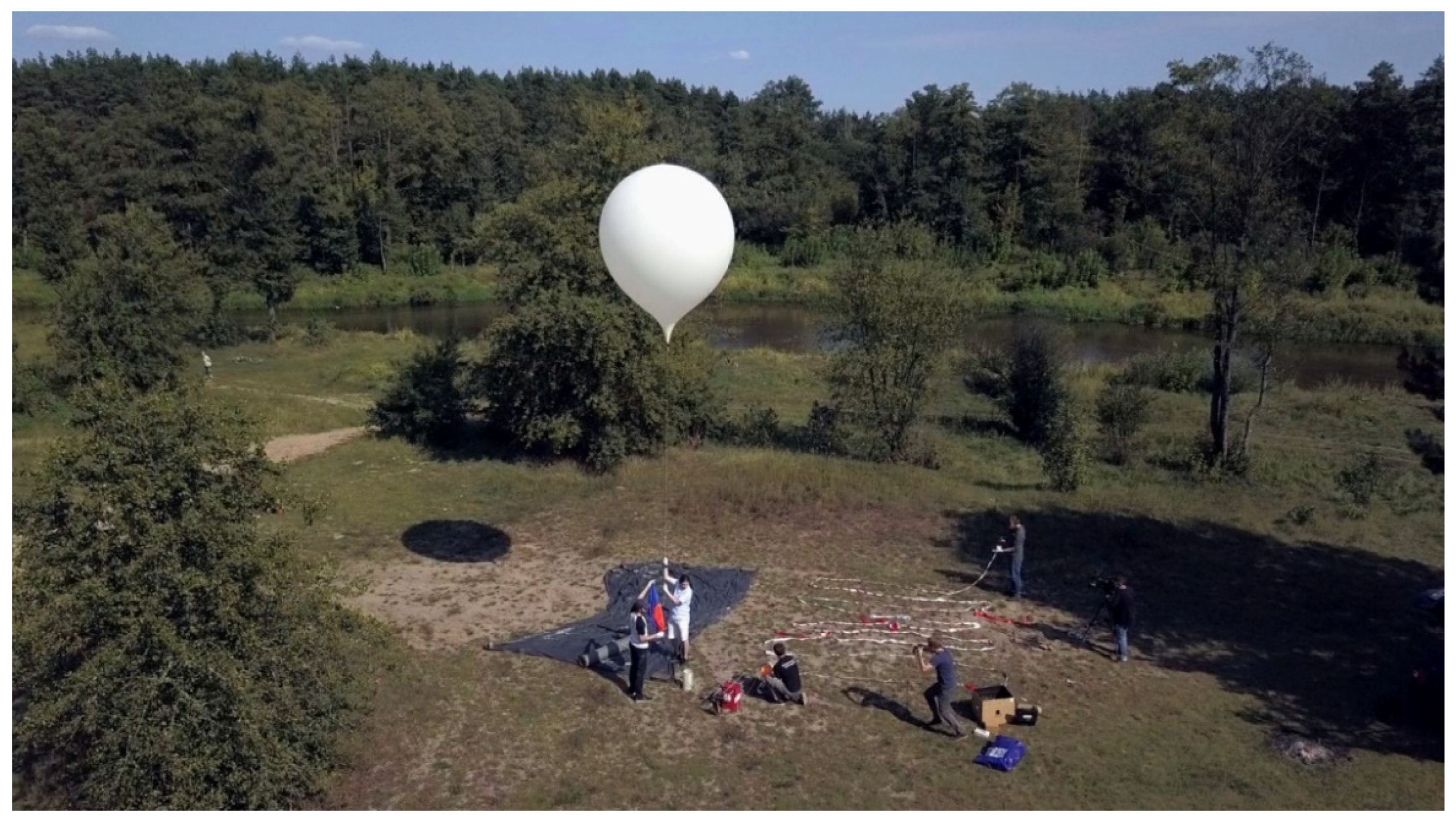
2.2. Experimental Setup

An experimental setup was constructed using two copper electrodes: one that was flat and circular with a diameter of 220 mm (with rounded edges) and one spherical with a diameter of 110 mm. The flat electrode was placed on a plastic insulator positioned on a wooden table; the spherical electrode was suspended on a copper wire from overhead output of one of the poles of the Greinacher-type high voltage generator (the flat electrode was connected to its second pole). The measured distance between the electrodes was 58 mm. The Greinacher generator was operated manually with constant indication of the generated high voltage and optional polarization switching.
The flat electrode was covered with balloon latex, supplied by the Students’ Space Association’s Balloon Division and originally manufactured by Pawan (India). The latex came from a balloon that was used in stratospheric conditions two months earlier (the latex was not degraded) and lost its initial talc cover, which enabled the manipulation of its amounts in the experiments. The talc in the experiments was of pharmaceutical grade, supplied by PF ZIOŁOLEK (Poland). Figure 3 presents the shape of this talc’s particles in magnification.

2.3. Experiment Results

The experiments were grouped into three stages (latex, latex + talc as on a typical balloon, and talc loose on latex), with two polarizations per stage. Similar to the notation adopted in [7], a polarization was employed, with the upper electrode given as ‘+’ and the lower given as ‘−’, with the former named ‘positive’ and the latter named ‘negative’. For each stage and set, the value of the maximum reachable voltage is given (the flashover voltage) as a mean value over multiple measurements/flashovers. Figure 4 presents the experimental setup with the talc-less latex cover; Figure 5 shows aggregated flashovers for the loose-latex stage. Figure 6 presents the plotted mean flashover voltage values for different stages and polarizations.
For the ‘latex’ and ‘talc’ (meaning the loose talc layer on the latex) cases, the observed tendency of the difference between the polarization cases remains nearly the same, with a small decrease in the flashover voltage associated with the presence of talc particles moving between the electrodes along the local electric field lines, causing a change in the conductivity of the air gap. For the positive polarization, the flashover voltages do not change drastically. For the negative polarization (upper electrode ‘−’; lower electrode ‘+’) and the ‘latex + talc’ case, the difference is significant: the talc, covering the latex envelope in a typical quantity for a latex balloon, i.e., with dominating surface viscous forces, changes the overall capacitance of the system, allowing more electric charge to be accumulated and discharged under a significantly higher voltage; however, this is not visible for the positive polarization, which—if clouds are considered—is only one out of four natural environmental polarizations or charges encountered in real conditions [24].
The apparent change in the system’s capacitance for the ‘latex + talc’ case is not related to any macroscopic change in the geometry of the electrode system; therefore, its change can be calculated by adapting the simple formula for a DC capacitor:
Q 2 = Q 1 + ( U 2 U 1 ) C
where Q is the electric charge (C) and U (V) is the max./flashover voltage; the indexes 1 and 2 denote the pure latex case and the ‘latex + talc’ (or ‘talc’) case, respectively. The capacitance C (F) can be approximated using the following formula for a conducting sphere over a conducting flat surface [25]:
C = 4 π ε 0 a a h 1 ( a h ) 2 ( 1 a h )   ( h a )
where ε0 is the electrical permittivity equal to 8.854 × 10⁻¹² F/m, a (m) is the radius of the spherical electrode, and h (m) is the distance between the center of the spherical electrode and the conducting surface. If, for the Equation (1), two sets of comparisons are calculated per each polarization (‘latex + talc’ or ‘talc’), a table of differences with respect to the maximum accumulated electric charge in the system can be presented (Table 1).
For the negative polarization, the difference in the amount of electric charge stored in the system is one degree of magnitude higher than that for the positive polarization; for all cases except the negatively polarized ‘latex + talc’, the electric charge decreases, which indicates a lower flashover voltage and a higher danger/higher risk of lightning strike. The only risk-reducing influence of talc was found for the negative polarization ‘latex + talc’ case.

2.4. Talc in Particle Discharging Mechanism

If the lower electric charge stored for the cases mentioned in Table 1 is related to the facilitated occurrence of a lightning strike due to the modified properties of the air gap between the electrodes, as the charged particles moved into the electric field through this gap, with the effect clearly visible on the spherical electrode in Figure 5, pulverized talc may therefore be considered as a way of reducing the system’s electric charge (either actively or passively) by removing it with its particles (particle discharging), proposed previously in [12], but for different materials. The operation of such a mechanism could be described as a multiplication of the volumetric concentration of talc particles n (m−3) around the object being discharged and the mean electric charge q ¯ (C) of a talc particle. While n can be modelled, in the basic/simplest case, as a linear function of the accelerating voltage, the q ¯   value needs to be estimated separately.
In order to do so, the extreme cases (talc/no talc) of the flashover experiments have to be taken into account and an approximated electrical model of the inter-electrode space has to be constructed. If the air gap with the moving charged particles is considered as a case roughly similar to a cold plasmatic environment (charged particles with low energies and low temperatures), its conductivity σ (S/m) can be expressed as [26]:
σ = n q ¯ 2 m ¯ τ
where m ¯ (kg) is the mean mass of a talc particle and τ (s) is the momentum transfer time between the particles. In this case, the talc particles are assumed to travel straightly along the local electric field lines to the intercepting electrode, with no (or no significant) collisions with other particles. With this assumption, a movement of a single particle of mass m ¯ and electric charge q ¯ can be described by an Euler–Cauchy second order linear ordinary differential equation, which yields a solution from which the air gap traversal time t (s) can be derived [27]:
t = 2 x ( t ) q ¯ m ¯ E m a x . + L ¯ m ¯ g  
where x(t) (m) is the distance between the electrodes, Emax. (V/m) is the maximum electric field at which the particle can be expulsed, L ¯ (N) is the mean viscous force acting on the particle (related to the substrate, i.e., the latex), and g (m/s2) is the terrestrial gravity acceleration. If the distance between the electrodes is assumed as a constant δ (m) and to this value the electric field strength is related, the following formula is obtained:
t f = 2 δ q ¯ m ¯ U m a x . δ + L ¯ m ¯ g  
describing the particle travel time tf (s) for the Umax. (V) voltage.
Substituting τ in Equation (3) with tf from Equation (5) renders:
σ = n q ¯ 2 m ¯ 2 δ q ¯ m ¯ U m a x . δ + L ¯ m ¯ g
For the two extreme cases of lack of talc (‘latex’, index 1) and freely expulsed talc particles (‘talc’, index 2), the L ¯ m ¯ ratio can be omitted, if it is assumed that the viscous forces are negligible in the ‘talc’ case. If relying on the change in the flashover voltages U1 and U2 to the changing conductivity of the inter-electrode air gap and its resistivities R1 and R2, the following proportion can be formed:
1 σ 2 = R 2 = R 1 U 2 U 1
This can be included in Formula (6), rendering:
n 2 = 1 R 1 U 1 U 2 m ¯ q ¯ 2 q ¯ m ¯ U m a x . δ + L ¯ m ¯ g 2 δ
The value of n2 (m−3)—the concentration of particles in the air gap—remains unmeasured for the second case (‘talc’); however, for the first case it can be approximated with relatively small numbers, equivalent to residual talk particles that may have appeared in the air gap after cleaning the electrodes (as the experiment site was not situated in a cleanroom). For the 1st case, U2U1, n1 becomes n2 and Umax. = U1, yielding the following formula:
n 1 = 1 R 1 m ¯ q ¯ 2 q ¯ m ¯ U 1 δ + L ¯ m ¯ g 2 δ
This formula can be regrouped with q ¯ as the variable, giving a 4th degree polynomial equation:
q ¯ 4 2 δ ( n 1 R 1 m ¯ ) 2 q ¯ U 1 m ¯ δ + g L ¯ m ¯ = 0  
An all-positive root of this equation can be estimated by the Mathematica software as:
q ¯ 1 2 α + β + 1 2 2 U 1 m ¯ δ 2 δ ( n 1 R 1 m ¯ ) 2 α + β β α                                                                    
α = 3.4943 ( g L ¯ m ¯ ) 1.7321 27 4 δ 2 ( n 1 R 1 m ¯ ) 4 U 1 4 m ¯ 4 δ 4 256 8 δ 3 ( n 1 R 1 m ¯ ) 6 ( g L ¯ m ¯ ) 3 + 18 δ ( n 1 R 1 m ¯ ) 2 U 1 2 m ¯ 2 δ 2 3          
β = 0.38157 2 δ ( n 1 R 1 m ¯ ) 2 1.7321 27 4 δ 2 ( n 1 R 1 m ¯ ) 4 U 1 4 m ¯ 4 δ 4 256 8 δ 3 ( n 1 R 1 m ¯ ) 6 ( g L ¯ m ¯ ) 3 + 18 δ ( n 1 R 1 m ¯ ) 2 U 1 2 m ¯ 2 δ 2 3          
By omitting the viscous ratio L ¯ m ¯ and defining the remaining constants, namely, R1 = 3.3 × 10¹⁶ Ωm (approximate free air conductivity), m ¯ = 10−9 kg, δ = 58 mm, U1 = 149 kV (for positive polarization) or 122.33 kV (for negative polarization), and setting n1 = [1; 10; 100; 1000], a plot of the calculated q ¯ (mean electric charges per one talc particle) as power-interpolated functions of n1 can be created. The chosen values of the variable n1 are, however, too wide to clearly define a viable range of the values of q ¯ ; to facilitate this, a range of the highest probability of the values of n1 can be chosen [28] as being between 10 and 100 and having a log-normal (asymmetric in linear scale) distribution [29] given by the following equation:
f ( n 1 ) = 0.4343 n 1 s 2 π e 1 2 ( l o g n 1 m s ) 2
where s (−) in the shape factor of 0.2 [29] and logn1 (−) is equal to 1.74, based on the chosen range of n1 [28].
Figure 7 shows both the curves of q ¯ as the functions of n1 and the f(n1) log-normal distribution, which can be used to determine (based on the assumptions made above) the most probable values of the electric charge of an average single particle of a pharmaceutical-grade talc. For the maximum value of the f(n1) distribution, the absolute values of the electric charges are 100.655 fC for the positively-polarized case (a moving talc particle that is negatively charged) and 91.924 fC for the negatively polarized case (a moving talc particle that is positively charged).
The definition of the approximate values of the electric charges of single talc particles shall allow for the formulation of the electric charge flow (or current) in the discharging mechanism by talc particle expulsion:
Q V   t a l c ( t ) = q ¯ n ( t )   [ C m 3 s 1 ]    
In this formula, however, the talc particle concentration n is a time-dependent variable, while in the previous formulas is was a stationary parameter. From the experiments, the n(t) function can be approximated by analyzing the number of particles intercepted by the spherical electrode (see Figure 5) and counting these particles per unit of surface on a corresponding microscopic image—shown in Figure 8. The number of particles (their surface density) nel. was estimated as 5.8 × 10⁸ m−2.
As this parameter is a product of the particles’ accumulation linearly at time tacc. for the n2 particle concentration (which increases in value with the voltage across the air gap, as more particles are expulsed), a function of it can be formulated:
n e l . = 1 2 t a c c . n 2 = 1 2 t a c c . n 1 U 2 U 1     [ m 2 ]
Assuming that the n(t) function remains proportional to time t (as a linear function), it can take the form (using Equation (16)):
n ( t ) = A A r e f . n 2 t a c c . t = A A r e f . n 1 2 U 2 2 2 U 1 2 n e l . t   [ m 3 s 1 ]      
where A/Aref. is the ratio of the actual talc-covered surface to the surface covered by talc in the experiments (the ‘talc’ cases), under the condition that the talc is not bound to the surface by the viscous forces.

3. Balloon and Antenna Model Discharges

The second part of the laboratory investigation was the determination of the basic properties of lightning striking a very long conducting object, made of different materials, and hovering in space (at tropospheric pressure) in the electric field of different polarizations.

3.1. Discharges over A Flexible Model

To demonstrate the forms of the strikes, as well as an exaggerated influence of the electrostatic forces resulting from the external electric field, an approx. 1:100 scaled simplified model of the flight train was constructed, whose specifications are as follows: a plastic sphere (no talc) of 30 mm trailing a 420-mm-long, narrow, fully flexible aluminum wire; the lower end of the wire was secured with a small weight made of insulating tape. The same tape was used to affix the wire to the balloon-imitating sphere. The model was suspended on two rods made of fiberglass (to exclude any possible influence on the experiment due to their excessive conductivity [19]). The position of two copper spheres, each 110 mm in diameter, acting as the electric field generators for the inception of the lightning strikes, was modified:
axial position: upper air gap—45 mm, and lower air gap—130 mm or 48 mm (see Figure 9);
lateral position (upper sphere moved to the left and levelled with the balloon; lower sphere moved to the right, below the antenna’s lower end): upper air gap—90 mm and lower air gap—150 mm.
The weight/density of the model antenna wire was chosen so that it would be light enough to provide a high electrostatic-to-mass forces ratio, which allowed for the demonstration of the movement and/or the amplitude of oscillating movements of the model subjected to high electric field intensities, which are to be used as an input for further analysis of the antenna’s radiation characteristics (which depend on its shape in space) and the flight dynamics of the entire flight train.
Similar to the discharges over the latex- and talc-covered electrode, the discharges were generated by a Greinacher-type high-voltage generator with polarization switching. Figure 10 and Figure 11 present the simulated lightning strikes in the axial and lateral electrode positions, respectively; Figure 12 shows the actual damage to the model after the discharges. In Figure 13, the flashover voltages for the two polarizations and both electrode positions are presented.
The experiments have shown a confirmed type of bidirectional discharge, which frequently occurs in aviation: the relative proximity of the balloon model to the center of the local electric charge (the copper electrode), as seen in Figure 10a, allowed the corona to visibly appear before the actual flashover. The dielectric balloon model did not take part in the formation of the conductive path, as all the damages are situated below it (as in Figure 12); however, a dielectric surface is able to acquire an additional substantial electric charge [30], which would form an electric field around the spherical object according to the formula [31]:
E e x t . = σ 0 c o s θ 3 ε 0 = q s u r f . c o s θ 2 π ε 0 r
where qsurf. (C) is the electric charge, r (m) is the radius of the sphere, and θ (deg) is the angle between the central axis of the sphere and the radius r. In the experimental case discussed, the central axis of the sphere is also the central axis of the flight train; along this axis, the electric field strength achieves its maximum values. The maximum value on the balloon’s lower pole is also influenced by the electric field from the electrified antenna wire (in a worst-case scenario, a superposition of the electric fields)—it is most likely due to this phenomenon that the corona tends to converge to this region. In real conditions, a latex balloon flying through the atmosphere with a substantial (tropospheric) density takes the shape of an ovoid with its upper pole significantly flattened due to the gas displacement inside the latex envelope, which would reduce the electric field strength on the top of the balloon in comparison to its theoretical description (18), presenting its lower pole as most electrical risk-subjected zone.
The flexible models have presented intense movements in all the flashover cases. As the conductive antenna wire was subjected to the differentiation of its electric charge (however, no dedicated discharging components were added to the model), the exaggerated forces in the electric field started to move the model; its lower part exhibited high-amplitude oscillations around the lower electrode (the lower center of electric charge), its upper part—saturated with the electric charge of the opposite sign—tended to move the entire flight train towards the upper electrode. This behavior was noted in both positions of the electrodes, albeit in the axial position it was sporadic; for the lateral position (see Figure 11), this movement allowed for the excitation of an intense corona (while the lower part of the wire remained oscillating, and no coronae appeared in proximity to the balloon). The movement of the antenna wire and the modified formation of the discharge would explain the sudden drop in the flashover voltage for the positive polarization case, as seen in Figure 13 for the lateral electrode position.

3.2. Discharges over A Stiff Model

To eliminate the effect of the model’s movement due to excessive forces in the electric field in order to investigate the behavior of different antenna materials, a set of two wire antennas was constructed: one made of copper wire (1.5 mm in diameter), one made of aluminum wire (1.5 mm in diameter), both straightened and with stripped insulations and affixed alternatively onto the fiberglass rod system (as in the previous experiments); the model balloon was omitted in this case, as the electrodes were placed in a lateral position only, in proximity to the wires, with a 45 mm air gap for the upper electrode and 50 mm of air gap for the lower electrode.
Figure 14 shows the bidirectional discharges over the antenna wires (with Figure 15 showing the enlarged portions of the upper parts); the flashover voltages have been plotted in Figure 16.
The two antenna models present extremely different characteristics of the inception of a lightning strike. While the form of the discharge itself remains similar for both cases, the copper case presents highly concentrated, punctual corona sources, resembling the St. Elm’s lights; the corona sources on the aluminum wire appear as less discrete, expanded over larger parts of the wire. As the corona discharges have the property of excitation in a geometrically convenient space, the micro-changes in the wire’s surface structures, such as micro-scratches and micro-cracks, must be taken into account, as the corona formation—especially in Figure 15a—is incepted in such locations. As the wires were mechanically treated similarly, and—for this diameter range and any microscopic deviations from it—since the corona excitation electric field strength does not vary significantly [11], another property of the wire’s material can be taken into account: the work function, or Wf, measured in electron-volts. With this parameter, the facility of electron expulsion from the material can be attributed to different materials, different voltages, and two considered polarization changes. Figure 16 presents the experimentally obtained mean values of the flashover voltages as a function of the mean work function values for the wire materials.
It can be noticed that the aluminum, possessing lower mean values of the work function, is more susceptible to changes in the mean flashover voltages for different polarizations, with higher voltage values for the upper electrode that is positively polarized. However, the mean flashover voltage values for the copper antenna remain the same.
During the experiments, the expanded shape of the excited corona over the aluminum wire also provoked the inception of a multiple-leader (branching) bidirectional lightning strike, as seen in Figure 17. The branching occurred for both zones (upper and lower) of the antenna wire, with all branches having similar tortuosities and thicknesses, indicating an evenly distributed electric charge flow (the total discharge current through the system).

4. Discussion

The experiments with the talc application, which closely resemble the real-condition applications, have shown the ability of the talc powder to carry an electric charge in a dry environment; however, the strongest influence on the flashover voltage was found for a single case only (out of total four cases with talc), namely, that involving negative polarization and the amount of talc powder with significant viscous forces, attracting it to the latex surface. The negative polarization in this case indicates a difference in the electric charges of the charged object and the external environment, with the external electrode being charged negatively; however, the aforementioned discharge behavior would also be expected to be observed for both the object and external electrode when charged negatively, but with a substantial difference in the charge magnitude (e.g., the object charged lightly). For the other three cases including substantial amounts of talc, its use can be described similarly to powders used as active dischargers [12], where the particles, regardless of their electrifying properties, take away a portion of the craft’s electric charge, moving it into the space around the craft. In the described experiments, the only force that moved the particles away from the charged object was the force in the external electric field; however, in real flight conditions, substantial mass forces (aerodynamic forces) would greatly accelerate this process and would be expected to reduce the ‘latex + talc’ voltages in Figure 7 even lower. The effectiveness of such a mechanism is directly tied to the actual mass of talc powder available on the craft.
Based on the Equation (9), the range for the electric charges of the talc particles for the given particle parameters was provided; in the equation, the parameters bounding the mean particle electric charge with the talc powder are associated with the particle dynamics in the external electric field (the Euler–Cauchy equation solution (5)). Formula (9) can be derived in an alternative way by substituting the n2 value in (8) with Formula (17) (for A/Aref. = 1) and (16), achieving a formulation for n1.
The calculated values (using the chosen log-normal distribution) of the electric charge of a mean talc particle can be compared with other existing data on the electric charges for precipitation and laboratory experiments (see Table 2); the same order of magnitude can be found for the calculated talc q ¯ and the precipitation in storm conditions. However, the calculated range of talc q ¯ is large enough to be able to find more similarities, if the considered n1 values are greater than 100.
The flexible wire experiments have shown the basic movement characteristics of a long vertical antenna system, which for the lateral external electrode position resembled a double-pendulum. The maximum observed amplitude of the wire’s oscillations showed a rotated V-like position of the antenna, which would distort its radiation characteristics. The forces acting on the wire could be reduced by providing a sufficient electric charge reduction on the wire; however, this would potentially facilitate the inception of coronae and flashovers below the values indicated in the experiments. For the lateral electrode position, the discharges were observed at lower voltages, indicating a riskier case than the axial electrode position.
In the axial cases, the entry and exit of the discharges were always located on the extremal parts of the conducting wire (regardless of its oscillations or the presence of dielectrics). The model balloon was found to be practically transparent for the discharges; however, this condition could be subject to change if its envelope acquires more electric charge on its own. The microstructure of the excessively-charged envelope also presents a risk of micro-discharges, which has been previously reported as one of the sources of tire tubes’ degradation and a constant loss of air pressure [32].
The experiments with stiff antenna wire of different materials have shown the differences between the discharges over the materials of different work functions (Wf). For the aluminum wire, the differences between the polarization cases are apparent and can be associated with the ability of the external electric field to expulse the electrons from the wire material; for the copper wire, the effect is not clearly visible, possibly due to the presence of micro-cracks on the wire surface, which facilitated the inception of coronae before the work function effect could manifest itself. However, the concentration of coronae for the copper wire could point to exact locations where deeper, larger damages to the wire could be expected (as the range of the temperature of the discharge channels is in the order of kK [18]). A better overview of the influence of the work function on the discharge voltages in the considered experimental system could be achieved with more materials included in the tests, generating more points for the plot in Figure 16 (which in its current form can be treated as a basic outline of the phenomena).
The formation of the discharge channels is affected by the form taken by the corona appearing around the wire; for the more expanded, less-concentrated corona around the aluminum wire, it was possible to achieve multiple (branched) discharge channels, which—from the point of view of the flight train—doubly increased the number of potential mechanical failure locations. The simulated lightning strikes always manifested themselves along the shortest paths to the long conducting object, despite the fact that the shortest paths between the charged electrodes were located elsewhere.
If an important part of the flight train—similar to a radio transmitter using the wire as its antenna—is located between the entry and exit points of the discharges, it would be subjected to destructive electrical overload.
Despite their severity with respect to risk weight, lightning strikes—although more probable for the considered long vertical airborne antennas—are phenomena of rare occurrence; in all antenna experiments presented in [5], only in one case (200-m-long dipole, aluminum tape; flight through a rain cloud) was a possible signature of an airborne discharge registered: a signal recorded by the on-board audio recorder, placed in the middle of the dipole’s length. The signal’s spectrum is shown in Figure 18; it appeared as a relatively high-pitch oscillating tone, which could correspond to a nearby airborne electrical discharge [16,30]; however, its direct relation to the antenna itself remains unknown (no critical damage from a lightning strike was found on the tape’s surface).

5. Conclusions

In this paper, the inception of lightning strikes on two essential elements of a balloon mission equipped with a long vertical antenna—a talc-covered latex (balloon material) and the model of the linear antenna, made of different materials—was investigated.
The properties of talc, with which the latex balloons are covered, have been defined as capacitance-increasing for negative polarization (with the external electric charge being negative, and the object with talc being positively charged) at low quantities, and particle-discharging for other polarization cases at high quantities and with positive polarization at low quantities. Using experimental data and basic assumptions regarding the talc particle movement model, the range of its mean electric charge was defined with exact values of 100.655 fC (positive polarization case) and 91.924 fC (negative polarization case) for the maximum value of a log-normal talc particle distribution with a shape factor of 0.2 and the logarithm of the expected value of 1.74. For the function of talc as a particle-discharging pulverized agent, exact calculations of its required mass are crucial for the airborne employment of this method. The use of talc, however, may be considered as an effective passive way to reduce the risk of the excessive electrification of both the balloon and the elements of the flight train (with talc sprayed or glued to its surfaces), regardless of the polarization of the system.
The experimental electrical discharges on the flight train model have shown that the most dangerous (i.e., susceptible to the entries and the exits of the discharges) are the extremities of the antenna wire, regardless of its movement, and the poles of the balloon. The excessive movement of the wire in strong electric fields could be included in the equations of its flight dynamics as a verification, in order to ensure that the antenna does not take a form that distorts its radiation characteristics.
The extremities of the antenna wire are considered the best locations for the passive corona discharge elements, which could be made of mechanically conditioned copper or aluminum. A general dependence on the antenna material’s work function values has been presented. The inception of corona discharges over an aluminum wire presents a wider range of possible locations on the wire, which could reduce the effectiveness of the operation of the dedicated corona discharges and endanger wider parts of the wire (a cover/insulation for the wire or a different metal/material could be considered). The form that takes a bidirectional lightning strike over the long vertical antenna wire, including the fact that the most probable entry and exit locations are at the wire’s extremities, poses a severe risk of the antenna transmitter’s overload and destruction; this risk could be reduced by either a disconnection of the transmitter in adverse environmental conditions, the oversizing of its power amplifier (in order to endure the overload), and/or a reduction in the coupling between the antenna wire and the transmitter.

Author Contributions

Conceptualization, T.A.M.; methodology, T.A.M. and M.C.; validation, T.A.M. and M.C.; formal analysis, T.A.M.; investigation, T.A.M.; resources, T.A.M.; writing—original draft preparation, T.A.M.; writing—review and editing, T.A.M. and M.C.; visualization, T.A.M. and M.C.; supervision, J.M.; project administration, J.M. All authors have read and agreed to the published version of the manuscript.

Funding

This research received no external funding.

Institutional Review Board Statement

Not applicable.

Informed Consent Statement

Not applicable.

Data Availability Statement

Not applicable.

Acknowledgments

The authors would like to thank the Students’ Space Association’s Balloon Division for the donation of the balloon envelope for experimentation.

Conflicts of Interest

The authors declare no conflict of interest.

References

  1. Burrows, M.L. ELF Communications Antennas; Peter Peregrinus Ltd.: Herts, UK, 1978. [Google Scholar]
  2. Durrant, R.F. Radio experiences in the R-34. Radio Amateur News, December 1919; p. 295. [Google Scholar]
  3. Miś, T. The concept of an airborne VLF transmitter with vertical electric dipole antenna. In Proceedings of the 2018 IEEE International Symposium on Antennas and Propagation & USNC/URSI National Radio Science Meeting, Boston, MA, USA, 8–13 July 2018. [Google Scholar] [CrossRef]
  4. Miś, T.A.; Modelski, J. Stratospheric VLF Vertical Electric Mono- And Dipole Antenna Tests in 2014–2015. In Proceedings of the 2018 Baltic URSI Symposium (URSI), Poznań, Poland, 14–17 May 2018; pp. 566–570. [Google Scholar]
  5. Miś, T.A. Experiment-based risk evaluation for a stratospheric VLF antenna system. In Proceedings of the IEEE International Symposium on Antennas and Propagation & USNC-URSI Radio Science Meeting, Denver, CO, USA, 10–15 July 2022. [Google Scholar]
  6. Miś, T.A. Flashover Analysis of Near-Space Antenna Mounting Insulators. In Proceedings of the 13th European Conference on Antennas and Propagation (EuCAP), Kraków, Poland, 31 March–4 April 2019. [Google Scholar]
  7. Miś, T.A.; Modelski, J. In-Flight Electromagnetic Compatibility of Airborne Vertical VLF Antennas. Sensors 2022, 22, 5302. [Google Scholar] [CrossRef] [PubMed]
  8. Miś, T.A. Investigation on the mature storm cloud’s electric field using long airborne antennas. In Proceedings of the National Conference of Radiocommunication, Radio Broadcasting and Television KKRRiT & National Symposium of Telecommunication and Teleinformatics KSTiT, Warsaw, Poland, 7–9 September 2022. [Google Scholar]
  9. Robledo-Martinez, A.; Garcia-Villareal, A.; Palacios, G.; Vera, A.; Sobral, H. Characteristics of the discharge of a charged dielectric in low-pressure air. J. Electrost. 2015, 76, 152–158. [Google Scholar] [CrossRef]
  10. Burdukova, E.; Laskowski, J.S.; Bradshaw, D.J. Surface properties of talc and their effect on the behaviour of talc suspensions. In Proceedings of the 23rd International Mineral Processing Congress IMPC, Istanbul, Turkey, 3–8 September 2006. [Google Scholar]
  11. Parker, K.R. (Ed.) Applied Electrostatic Precipitation; Blackie Academic & Professional: London, UK, 1997. [Google Scholar]
  12. Hall, W.C. Electrostatic dischargers for aircraft. J. Appl. Phys. 1947, 18, 759–765. [Google Scholar] [CrossRef]
  13. Sugimoto, T.; Kikuchi, H.; Higashiyama, Y. Positive discharge from a grounded electrode toward negatively charged particles cloud. J. Electrost. 2005, 63, 609–614. [Google Scholar] [CrossRef]
  14. Jaworek, A. Measurement Methods of the Electrostatics; Institute of Fluid-Flow Machinery, Polish Academy of Sciences: Gdańsk, Poland, 1985. [Google Scholar]
  15. Kopcewicz, T. The Atmosphere of the Earth; PZWS: Warsaw, Poland, 1948. [Google Scholar]
  16. Kowalska, B.; Łabudzki, S. Electrical discharges on the airplane. LOT Flight Pers. Bull. 1981, 2, 13–25. [Google Scholar]
  17. Sweers, G.; Birch, B.; Gokcen, J. Lightning strikes: Protection, inspection and repair. Aero Q. 2012, QTR_04, 19–28. [Google Scholar]
  18. Larsson, A.; Lalande, P.; Bondiou-Clergerie, A.; Delannoy, A. The lightning swept stroke along an aircraft in flight. Part I: Thermodynamic and electric properties of lightning arc channels. J. Phys. D Appl. Phys. 2000, 33, 1866–1875. [Google Scholar] [CrossRef]
  19. Pavan, C.; Fontanes, P.; Urbani, M.; Nguyen, M.C.; Martinez-Sanchez, M.; Peraire, J.; Montanya, J.; Guerra-Garcia, C. Aircraft charging and its influence on triggered lightning. J. Geophys. Res. Atmos. 2019, 125, e2019JD031245. [Google Scholar] [CrossRef]
  20. Qie, X.; Pu, Y.; Jiang, R.; Sun, Z.; Liu, M.; Zhang, H.; Li, X.; Lu, G.; Tian, Y. Bidirectional leader development in a pre-existing channel as observed in rocket-triggered lightning flashes. J. Geophys. Res. Atmos. 2016, 122, 586–599. [Google Scholar] [CrossRef]
  21. MINDAT: Talc. Available online: https://www.mindat.org/min-3875.html (accessed on 1 February 2022).
  22. Ribeyre, Q.; Bocquet, S.; Francqui, F.; Lumay, G. Measuring the influence of talc on the properties of lactose powders. Granutools 2018, 2018, 74–77. [Google Scholar]
  23. Yan, J.; Xu, L.; Tie, W.; Jiang, D.; Yan, B. Experimental investigation on radiation characteristics of RF electromagnetic pulse from atmospheric spark discharge plasma. Phys. Plasmas 2019, 26, 043301. [Google Scholar] [CrossRef]
  24. Imianitov, I.M.; Chubarina, E.V.; Shwarts, J.M. The Electricity of Clouds; National Scientific Publisher: Warsaw, Poland, 1974. [Google Scholar]
  25. Longcope, D. Capacitance of a Sphere near a Ground Plane–Images Charges to Infinity. Available online: http://solar.physics.montana.edu/dana/ph519/sph_cap.pdf (accessed on 4 July 2022).
  26. Frank-Kamieniecki, D.A. Lectures on Plasma Physics; PWN: Warsaw, Poland, 1968. [Google Scholar]
  27. Leyko, J. General Mechanics. Volume 2. Dynamics; PWN: Warsaw, Poland, 2002. [Google Scholar]
  28. Firkowicz, S. Statistical Examination of Products; WN-T: Warsaw, Poland, 1970. [Google Scholar]
  29. Gładysz, H.; Peciakowski, E. Reliability of Electronic Components; WKiŁ: Warsaw, Poland, 1984. [Google Scholar]
  30. Florkowski, M. Partial Discharges in High-Voltage Insulating Systems. Mechanisms, Processing and Analytics; AGH University of Science and Technology Press: Kraków, Poland, 2020. [Google Scholar]
  31. Durand, E. Electrostatics. Vol. I. The Distributions; Masson & Cie: Paris, France, 1964. [Google Scholar]
  32. Šimorda, J.; Staroba, J. Static Electricity in the Industry; WN-T: Warsaw, Poland, 1970. [Google Scholar]
Figure 1. Final stage of a latex balloon launch, with a 40 m long antenna [5] prepared on the ground.
Energies 15 06805 g001
Figure 2. A latex balloon in the stratosphere at the maximum altitude of >23 km (a) and a few seconds later after the burst (b). In (b), above the burst envelope, a large helium-talc cloud can be noticed, with the talc being sloughed off the latex envelope and carried away by the released helium. The pictured balloon carried a Very Low Frequency test antenna dipole of 200 m in length, described in more detail in [4].
Energies 15 06805 g002
Figure 3. Two microscopic views of the pharmaceutical-grade talc used in the experiments (100× magnification by PZO Poland microscope; max. dimension of each view is 1 mm). The smaller talc particles have multiple sharp, fibrous edges; the larger ones form flat, crystalline structures, with a high tendency for conglomeration.
Energies 15 06805 g003
Figure 4. The simulated lightning strike over a balloon latex surface (8 s exposure) and a hole burned through the latex by the lightning’s leader. The upper electrode moved slightly off the central axis of the setup, but in this case, it had no significant impact on the flashover voltage.
Energies 15 06805 g004
Figure 5. Various types of lightning strikes incepted for the loose talc surface on latex (8 s exposures). Most of them appeared along the central axis of the system (which is consistent with other experiments [23]), but not all of them; the formation of the discharge channel was affected by the talc particles moving in the electric field. Particles superheated and expulsed in the air can be seen near the talc surface and in the (a,c) discharge channels; channel (b) remains clear. It can be noticed that the upper electrode becomes covered with the intercepted talc particles; image (a) has been lighted differently during the exposure, apparently showing a different amount of talc powder accumulated on the electrode (in reality, it was constant in all three images).
Energies 15 06805 g005
Figure 6. Recorded mean flashover voltages for two polarizations and three considered cases of latex/talc configuration.
Energies 15 06805 g006
Figure 7. Calculated values of the mean electric charge per talc particle for different polarization cases, approximated as functions of the particles’ air concentration n1 and plotted against the log-normal distribution, showing the most probable range of actual n1 occurrence during the experiments.
Energies 15 06805 g007
Figure 8. The amounts of talc powder forming a uniform layer on the spherical electrode (as in Figure 5), seen at 100× magnification (PZO Poland microscope).
Energies 15 06805 g008
Figure 9. Flight train model suspended between the electrodes in the axial position.
Energies 15 06805 g009
Figure 10. A simulated lightning strike in the axial positions of the electrodes around the flight train model (polarization negative; 8 s exposure): image (a) presents the corona appearing shortly before the flashover; (b) the flashover with destructive impact on the lower end of the antenna.
Energies 15 06805 g010
Figure 11. A simulated lightning strike in the lateral position of the electrodes around the flight train model (polarization positive, 8 s exposure).
Energies 15 06805 g011
Figure 12. The damage to the flight train model due to the exit and entry of the discharges.
Energies 15 06805 g012
Figure 13. Collected mean flashover voltages over the flight train model for different polarizations, different electrode configurations, and varying total air gap distances.
Energies 15 06805 g013
Figure 14. Bidirectional discharges over two model antenna wires: (a) copper and (b) aluminum (image (b) is more enlarged than (a); both have an 8 s exposure). The tortuosity of the upper and lower discharges could be affected by the magnetic field generated by the current flowing through the wire during the discharge.
Energies 15 06805 g014
Figure 15. The enlarged images of the upper parts of the antennas subjected to bidirectional discharges: (a) copper and (b) aluminum (both 8 s exposure). Image (b) is more enlarged than (a). Different corona patterns can be noticed.
Energies 15 06805 g015
Figure 16. Recorded flashover voltages for two polarization changes as functions of the material’s work functions.
Energies 15 06805 g016
Figure 17. A branched case of bidirectional simulated lightning strike over an aluminum antenna wire (8 s exposure).
Energies 15 06805 g017
Figure 18. A spectrum of an acoustic phenomena recorded during the 200-m-long dipole antenna flight, possibly related to a nearby airborne lightning strike.
Energies 15 06805 g018
Table 1. Maximum accumulated electric charge differences for different comparison cases and polarizations. Case denoted as 1 in Equation (1) is ‘latex’ in all sets.
Differences in Charge (nC)
for Polarization +
Differences in Charge (nC)
for Polarization −
‘latex’–‘latex+talc’−68.89‘latex’–‘latex + talc’394.07
‘latex’–‘talc’−19.29‘latex’–‘talc’−42.44
ΔC between the cases49.60ΔC between the cases436.51
Table 2. Particle electric charges for different materials and conditions.
Particle Typeq (fC)SourceRemarks
talc, polarization +, mean100.655Figure 7log-normal distribution
talc, polarization −, mean91.924Figure 7log-normal distribution
precipitation, charge + and −1[24]rain inside the cloud
precipitation, charge + and −3 to 30[24]storm inside the cloud
tearing apart
a freezing droplet
0.2 to 2.7[24]experimental (lab)
Publisher’s Note: MDPI stays neutral with regard to jurisdictional claims in published maps and institutional affiliations.

