Article

Passivity-Based Control of Dual Active Bridge Converter in Constant Power Load Condition

1
School of Automation, Beijing Information Science and Technology University, Beijing 100192, China
2
Shenzhen Power Supply Corporation, Shenzhen 518048, China
3
National Active Distribution Network Technology Research Center, Beijing Jiaotong University, Beijing 100044, China
*
Author to whom correspondence should be addressed.
Energies 2022, 15(18), 6685; https://doi.org/10.3390/en15186685
Submission received: 23 August 2022 / Revised: 8 September 2022 / Accepted: 12 September 2022 / Published: 13 September 2022

Abstract

:
This paper presents a passivity-based control (PBC) based on the Euler–Lagrange (EL) model for dual active bridge (DAB) converters in the constant power load (CPL) condition. The EL model, which is derived from Kirchhoff’s current equations at the input and output nodes, is first presented in the DAB application, and the bidirectional CPL is considered in the theoretical analysis, simulation, and physical verification. The PBC has strong robustness to large-signal disturbance and negative incremental resistance load, and it is suitable for DAB converters in the CPL condition. In this paper, the DAB’s EL model, passivity analysis, stability analysis, and controller design are described in detail. The simulation results based on SIMULINK are also given in this paper. Finally, a DAB converter prototype is built to demonstrate the validity and feasibility of the proposed approach.

1. Introduction

In 1991, the dual active bridge (DAB) was proposed by R.W. De Doncker. It has the advantages of soft-switching, bidirectional power flow capabilities, buck–boost operation, galvanic isolation, high power density, and a high degree of modularization [1,2].
Thereafter, DABs gained increasing attention and practical application in low DC voltage and even in medium DC voltage when several DABs are series-connected to achieve higher voltage access [3,4,5]. DABs are the key component in DC distribution applications.
Normally, the power is transmitted by voltage stabilizing control or constant power control. The pulse modulation of fixing the primary side and lagging or leading the commutation of the secondary side according to the power direction is adopted [6].
Whether in constant power control or voltage stabilizing control with tight regulation, the load behaves as a constant power load (CPL) within its control-loop bandwidth. Its negative incremental resistance characteristic is generally the origin of the converter instability [7,8].
Some closed-loop regulations should be adopted to ensure the DAB’s stable operation and fast perturbation rejection. A novel Lyapunov-function-based control [9] and state-observer-based PI-PBC control [10,11] are presented to guarantee the converter’s global asymptotic stability. The full-order continuous-time average modeling of DABs was studied in [12]. The linear control, which is based on the small-signal model, is most popular in a DAB’s closed-loop control, and it mainly includes pole-placement control and PI control. However, pole-placement control has its disadvantages, such as its complexity and difficult implementation [13,14]. Although the proportional–integral (PI) control is simple and easy to implement, it suffers from the drawback of inconsistent performance across the entire operating range [15].
Some non-linear controls are also employed, including feedback linearization control, flatness-based control [16,17,18], model predictive control [19,20], sliding mode control [21,22], and virtual power control [23]. Although these non-linear controls can give high performance, they are complex and difficult to make ready for physical application.
The passivity-based control (PBC) is the most practical non-linear control technique due to its simplicity and easy implementation [24]. The PBC reshapes the dissipated energy from the system’s Euler–Lagrange representation and then injects a virtual resistance matrix to dampen the system and ensure its passivity [25]. Once every converter is guaranteed to be passive and stable, their interconnected or cascaded system is also passive and stable, so it is used in the power conversion system [26], rectifier [27,28], PV [29,30], STATCOM [31], and other converters [32,33].
In [34], the port-controlled phasor Hamiltonian (PCPH) model of DABs was proposed for the first time, but it is only valid for low-power applications because of its sinusoidal pulse width modulation, and it is only verified by Opal-RT and dSPACE simulators. Moreover, based on the PCPH model, [35] applied Interconnection and Damping Assignment PBC (IDA-PBC) to a DAB’s controller design; the hardware-in-loop (HIL) experiments and low-power prototype experiments were all performed in large-signal disturbance, but only resistive load was used in the verification, and the power flowed only from the primary to the secondary side. Although the CPL is considered in DAB-based shipboard power systems, it is only verified by simulation, and it needs further physical experimental verification [36].
In this study, the PBC based on the Euler–Lagrange (EL) model is applied to a DAB’s application for the first time, and the bi-directional CPL is considered in SIMULINK simulation as well as in physical experiments.
The rest is organized as follows. In Section 2, the DAB modeling in EL form is presented. Section 3 implements passivity analysis, stability analysis, and controller design sequentially. Later, in Section 4 and Section 5, respectively, the SIMULINK simulation and prototype implementation are described with results. Finally, Section 6 states the conclusion.

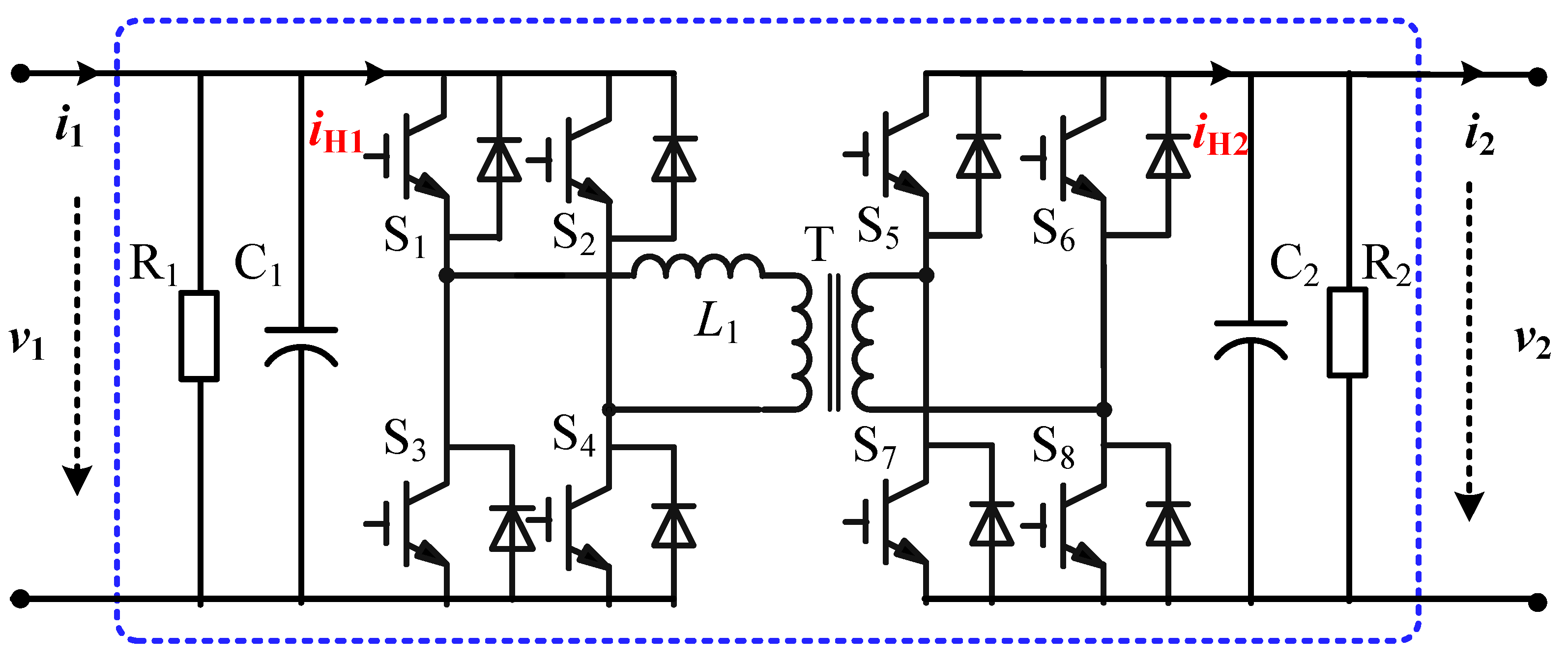
2. Topology Analysis

The DAB is made up of S1–S8, L1, T, C1, and C2, as depicted in Figure 1. S1–S8 are fully controlled power switches, such as MOSFET, IGBT, IGCT, et al.; S1-S4 make up the primary bridge converter; S5–S8 make up the secondary bridge converter; L1 is an inductor for energy exchange; T is a high-frequency (HF) transformer for voltage matching and electrical isolation; C1 and C2 are capacitors for primary and secondary filtering and energy exchange; and R1 and R2 are equivalent resistances to simulate primary and secondary power losses. A DAB converter can realize voltage conversion between different voltages with electrical isolation, and it can realize bidirectional power exchange at the same time.
According to the related research [2], the power transmitted by the DAB can be expressed as
P = N v 1 v 2 2 f s L 1 D ( 1 | D | ) ,
where N is the HF transformer’s turn ratio; v1 and v2 are the primary voltage and secondary voltage, respectively; fs is the switching frequency of the switches; and D is the phase shift duty ratio, which means that the phase shift time is equal to DTs/2, where Ts = 1/fs is the switching period.
It is assumed that the converter’s loss can be ignored, and the primary average bridge current and the secondary average bridge current can be described as
{ i H 1 = P v 1 = N v 2 2 f s L 1 D ( 1 | D | ) = K v 2 ω s L 1 , i H 2 = P v 2 = N v 1 2 f s L 1 D ( 1 | D | ) = K v 1 ω s L 1 ,
where
K = N π D ( 1 | D | ) .
According to Kirchhoff’s current law, we can further obtain the formula
{ C 1 d v 1 d t + 1 R 1 v 1 + K ω s L 1 v 2 = i 1 , C 2 d v 2 d t + 1 R 2 v 2 K ω s L 1 v 1 = - i 2 .
where i1 and i2 are the input and output currents of the DAB converter, respectively. Assuming the resistors, capacitors, and inductors are all time-invariant, the controller can be designed based on these differential equations, and its properties can also be exploited in the closed-loop system analysis.
If X = (v1, v2)T and V = (i1, −i2)T are selected as state variables and input variables, respectively, (4) can be expressed as a standard Euler equation in the form of
M X + J X + R X = V ,
where M is a positive definite symmetric coefficient matrix, i.e., MT = M > 0. J is a skew-symmetric coefficient matrix, i.e., JT = −J. R is a positive coefficient matrix, i.e., RT = R > 0, which means that the converter has a dissipative characteristic.
M = ( C 1 0 0 C 2 ) , J = ( 0 K ω s L 1 K ω s L 1 0 ) , R = ( 1 / R 1 0 0 1 / R 2 )

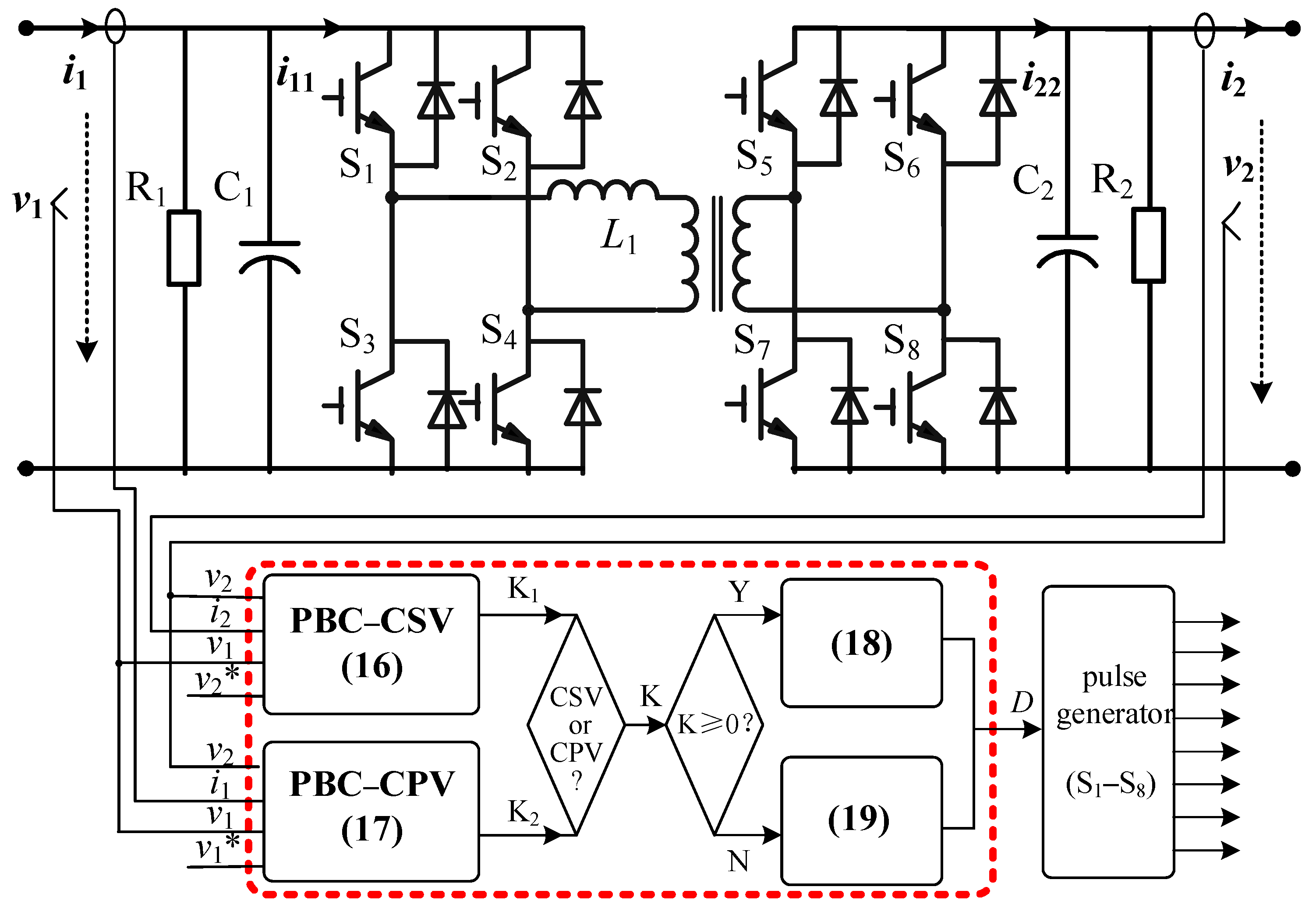
3. PBC Controller Design

3.1. Passivity Analysis

It is assumed that the energy storage function is
H = 1 2 X T M X = 1 2 ( C 1 v 1 2 + C 2 v 2 2 ) 0 ,
and the change rate of energy storage function can be obtained as
H = X T M X = X T ( V J X R X ) = X T V X T R X = v 1 i 1 v 2 i 2 ( v 1 2 / R 1 + v 2 2 / R 2 ) .
For all input variables V, if the output variable is selected as Y = X, and the function Q(X) is defined as v12/R1 + v22/R2, then (8) can be further rewritten as
H Y T V Q ( X ) ,
where Q(X) is a positive definite function. According to passivity theory, the DAB converter is strictly passive.

3.2. Stability Analysis

It is assumed that the reference value is X* = (v1* v2*)T, the error vector is Xe = XX*, and (5) can be further expressed in Xe form as
M X e + R X e = M X M X * + R ( X X * ) = V ( M X * + J X + R X * ) ,
Obviously, when X approaches X*, Xe will approach 0, and Equation (10) will be equal to 0, that is
M X e + R X e = V ( M X * + J X + R X * ) = 0 ,
On the other hand, according to (8), the change rate of storage energy function expressed in Xe form is
H e = X e T M X e = X e T R X e 0 .
Therefore, the value of dHe(Xe)/dt is not always 0 for any initial state Xe ≠ 0, and when ||Xe||→∞, there is He(Xe) →∞. Consequently, the designed PBC controller can realize the asymptotic stability of the DAB converter.

3.3. Controller Design

According to (11), the PBC controller can be designed as
V = M X * + J X + R X * ,
To accelerate Xe convergence to 0, a damping injection matrix is used, and (13) further becomes
V = M X * + J X + R X * - R d X e ,
where Rd = diag{g11, g22} is the damping injection matrix.
That is
{ i 1 = C 1 d v 1 * d t + K ω s L 1 v 2 + 1 R 1 v 1 * g 11 ( v 1 v 1 * ) , i 2 = C 2 d v 2 * d t K ω s L 1 v 1 + 1 R 2 v 2 * g 22 ( v 2 v 2 * ) .
When the DAB works in constant secondary voltage (CSV) mode, the control target value is reference v2*, and (15) can be simplified to
K = ω s L 1 [ i 2 + C 2 d v 2 * d t + 1 R 2 v 2 * g 22 ( v 2 v 2 * ) ] v 1 .
When the DAB works in constant primary voltage (CPV) mode, the control target value is reference v1*, and (15) can be further simplified to
K = ω s L 1 [ i 1 C 1 d v 1 * d t 1 R 1 v 1 * + g 11 ( v 1 v 1 * ) ] v 2 .
Whether in CSV or CPV mode, the variable K can be calculated from (16) or (17). Then, D can be obtained by solving the monadic quadratic Equation (3).
When K is greater than 0, D is also greater than 0, which means that the power is transmitted from the primary side to the secondary side, so we can obtain
0 < D = 1 2 1 4 K N π < 1 2 ,   when   K 0 .
When K is less than 0, D is also less than 0, which means that the power is transmitted from the secondary to the primary side, so we can obtain
1 2 < D = 1 2 + 1 4 + K N π < 0 ,   when   K < 0 .
According to the analysis above, (16) or (17) is used to calculate the variable K in CSV and CPV mode, respectively. Then (18) or (19) is used to calculate the phase shift duty ratio according to the power direction. The PBC control diagram is shown in Figure 2.

3.4. Closed-Loop System Stability Analysis
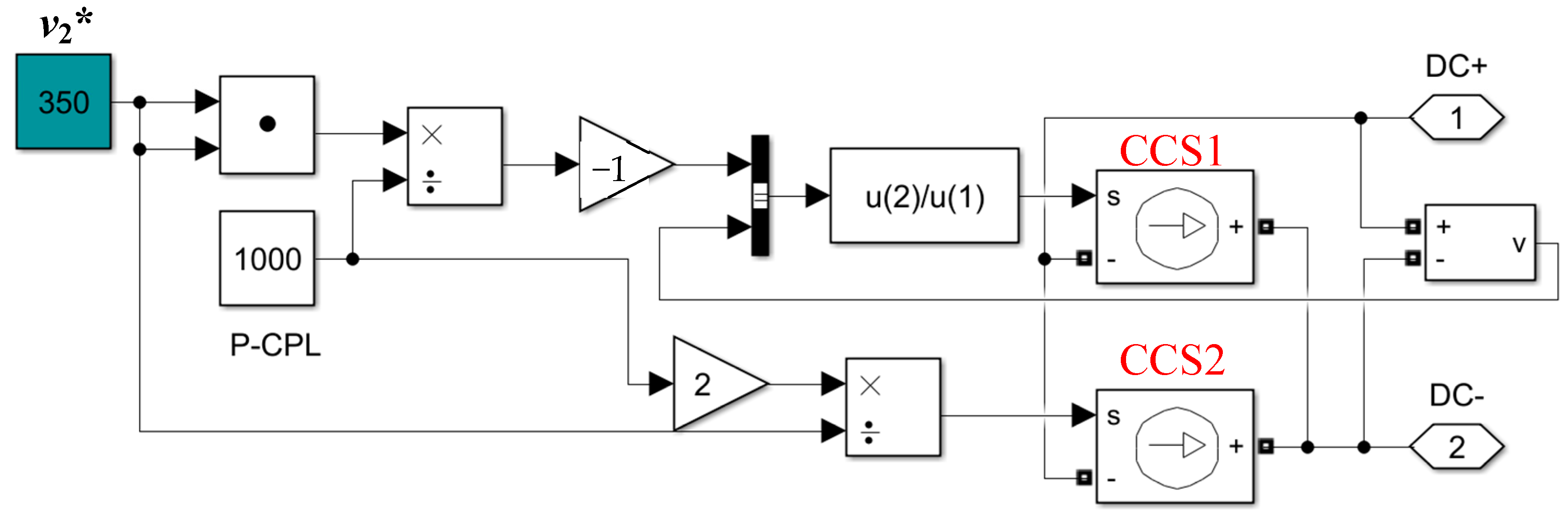
Substituting the control (15) into the system model (4), the closed-loop system can be written as
{ C 1 d d t x e 1 = 1 R 1 x e 1 g 11 x e 1 C 2 d d t x e 2 = 1 R 2 x e 2 g 22 x e 2
where xe1 = v1v1*, xe2 = v2v2*. We can select the Lyapunov function as
W ( x e 1 , x e 2 ) = 1 2 C 1 x e 1 2 + 1 2 C 2 x e 2 2 0
The time derivative of W(xe1, xe2) along the closed-loop system trajectory (20) is shown as
W ( x e 1 , x e 2 ) = ( 1 R 1 x e 1 g 11 x e 1 ) x e 1 + ( 1 R 2 x e 2 g 22 x e 2 ) x e 2 = ( 1 R 1 + g 11 ) x e 1 2 ( 1 R 2 + g 22 ) x e 2 2 0
Since Equation (21) is positive definite and Equation (22) is negative definite, the equilibrium state of the closed-loop system at the state space origin Xe = (xe1, xe2)T = 0R2 is asymptotically stable. Moreover, when ||Xe||→∞, W(Xe)→∞ is satisfied for any t ≥ 0. Therefore, according to the Lyapunov stability theorem, the closed-loop system is asymptotically stable in a large range of the equilibrium state.

4. Simulation

To validate the effectiveness of PBC based on the EL model for a DAB converter in the CPL condition, time-domain simulations are carried out in SIMULINK under voltage and power perturbation. The main parameters are listed in Table 1.
According to the CPL equivalent circuit, the CPL can be equivalent to the parallel connection of a CCS and a negative resistor. In the simulation, another CCS is used to control the negative resistor’s current, which is decided by power and voltage, as shown in Figure 3.

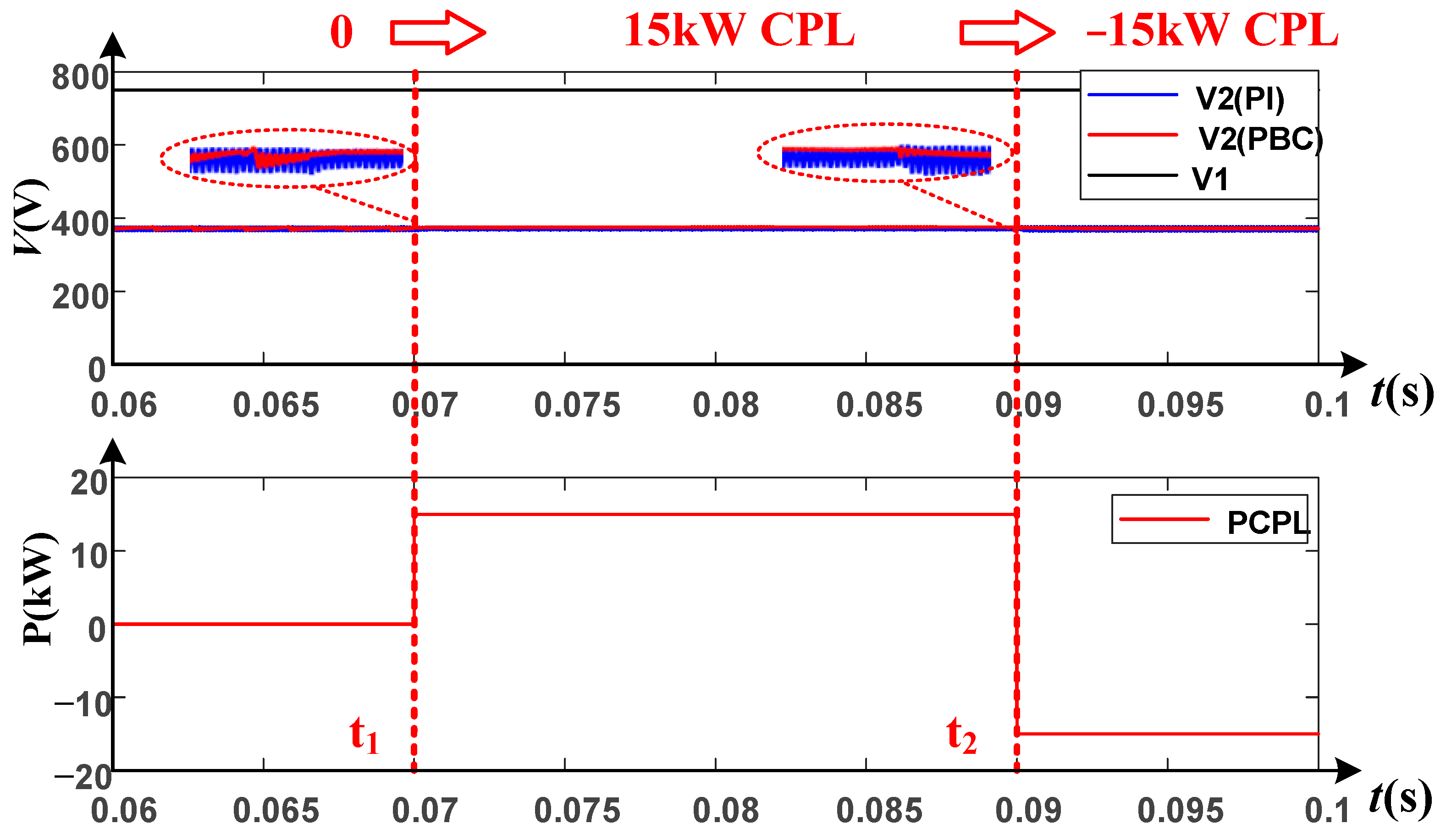
4.1. CPL Perturbation Simulation

Figure 4 shows voltages and power waveforms in the CPL step change simulation. In the simulation, a 750 V source supplies the DAB’s primary side, the CPL connects to its secondary side, and the reference v2* is set as 375 V. At the time t1, the power is set as 15 kW, then the power is set as −15 kW at the time t2.
It can be seen that the power tracks the reference value quickly without obvious voltage fluctuations, and it has a smaller ripple voltage compared with PI control. The PBC has a good response characteristic when a CPL perturbation occurs.

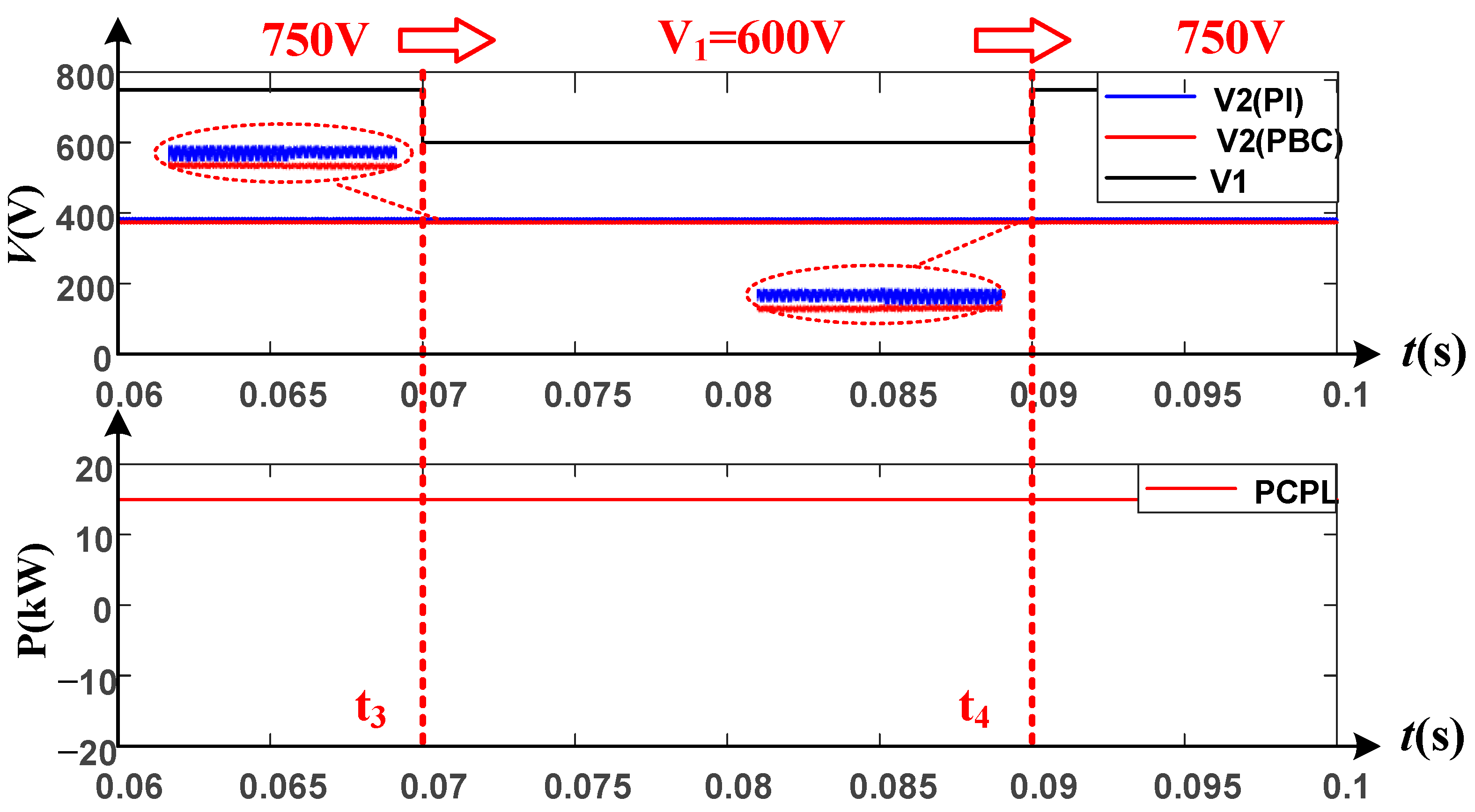
4.2. Source Perturbation Simulation

Figure 5 shows voltages and power waveforms in source perturbation simulation. In the simulation, a controlled voltage source (CVS) supplies the DAB’s primary side, the CPL also connects to the DAB’s secondary side, and the reference v2* is also set as 375 V. At the time t3, the power supply voltage decreases rapidly to 600 V and restores to the normal voltage at the time t4.
This shows that the secondary voltage v2 has no obvious fluctuations during the transient process, and PBC has better response characteristics and smaller voltage ripples compared to PI control when in the source perturbation condition.

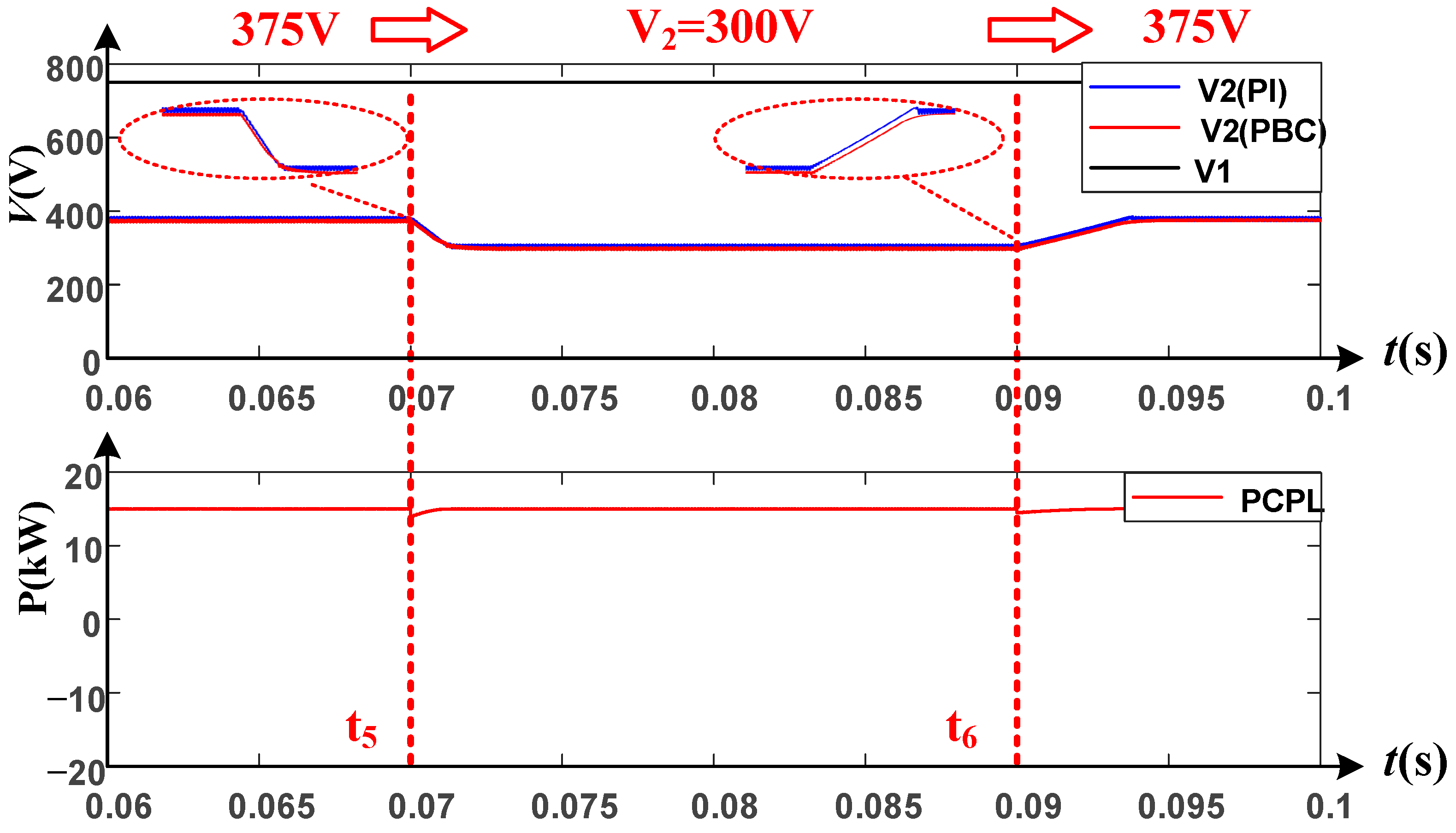
4.3. Voltage Reference Step Simulation
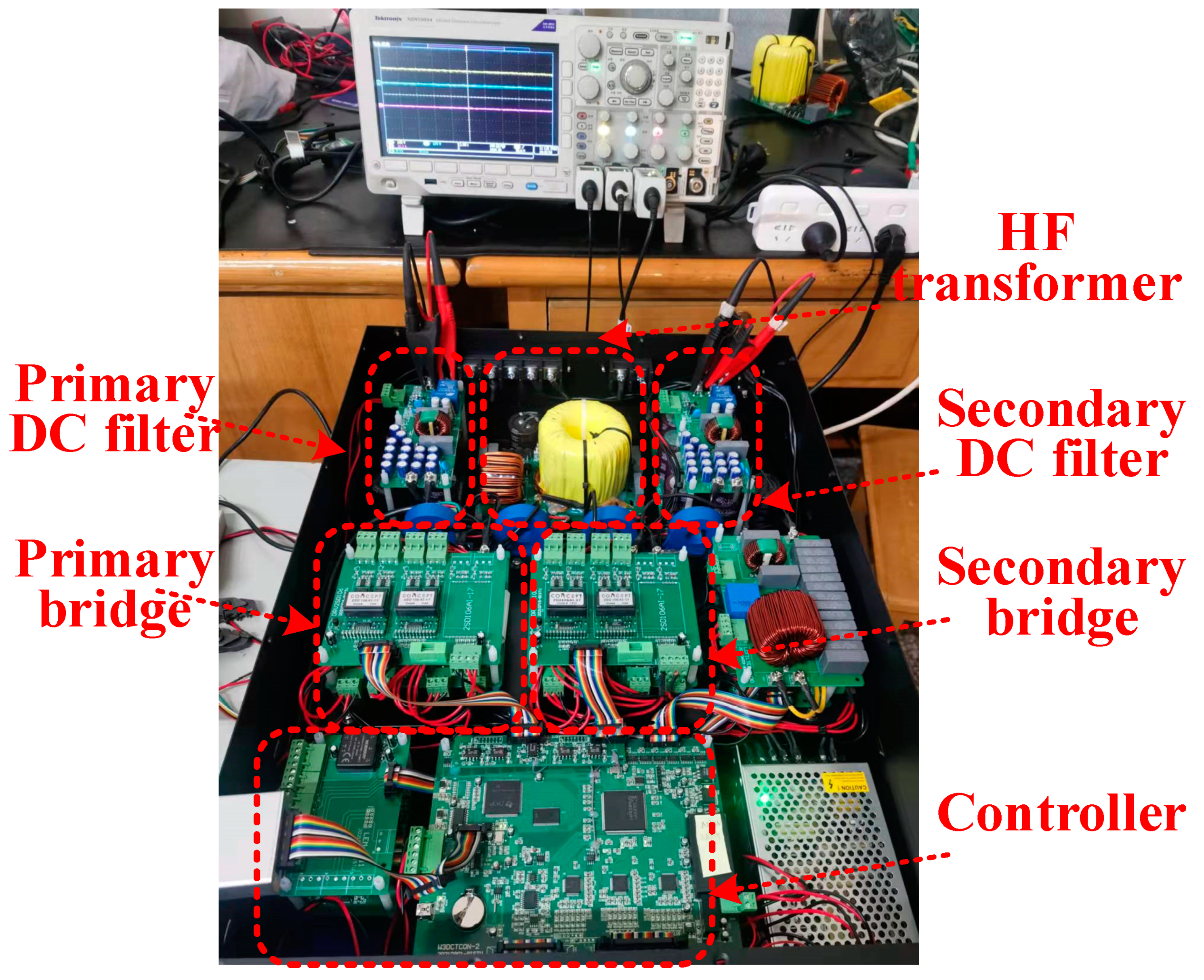
Figure 6 shows voltages and power waveforms in reference step change simulation. In the simulation, a power source supplies the DAB’s primary side; the CPL connects to the DAB’s secondary side. First, the reference v2* is set as 375 V, and it is set as 300 V at the time t5; then, it is reset as 375 V again at the time t6. This shows that the secondary voltage tracks the reference step with a transient process, and it also has good response characteristics.
Through the simulations, it can be concluded that the proposed PBC control can stabilize secondary voltage without obvious fluctuation, whether in a load or source perturbation condition or in a reference step change condition, and it has better response characteristics than PI control.

5. Experiment

The experimental setup, which is used for the validation of the proposed PBC based on the EL model, is presented in Figure 7, and its main circuit parameters are listed in Table 2. In the experiment, an electronic load APL-II (Myway company) is used to simulate a CPL, and a bidirectional power source PSB9750 (EA company) is used to simulate the power supply. Voltage perturbation, power perturbation, and reference step change experiments are also carried out in the platform.

5.1. Starting Experiment

Figure 8 gives the voltages and current waveforms of the DAB converter when starting the process. At the time t1, the DAB converter begins to start in CSV mode, and the secondary voltage increases gradually. At the time t2, the soft starting process ends, and the PBC control starts. At the time t3, the secondary voltage is stable at the set value (100 V), and the starting process ends.
This shows that the voltage overshot is about 8 V, the whole starting time is 1.6 s, and it has quick starting and low voltage overshoot characteristics.

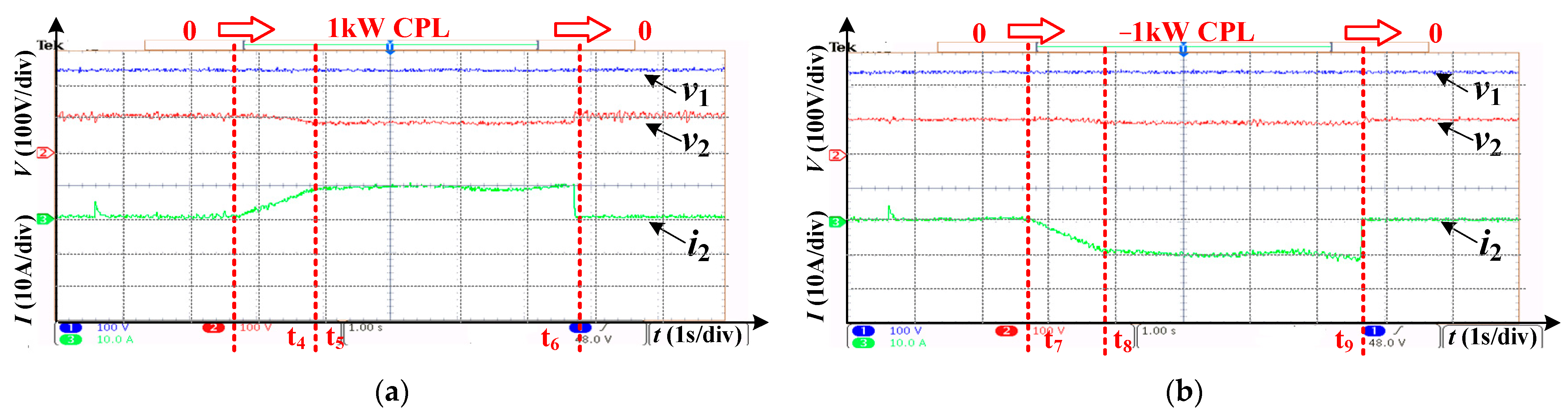
5.2. CPL Perturbation Experiment

Figure 9 gives the voltages and current waveforms of the DAB converter in the CPL perturbation experiment. In Figure 9a, the secondary voltage is stable at an initial 100 V. At the time t4, a 1 kW CPL switches on, and the secondary current increases gradually. At the time t5, the secondary current is stable at 10 A. At the time t6, the CPL is cut off, and the secondary current recovers to 0 quickly.
In Figure 9b, the secondary voltage is also stable at an initial 100 V. At the time t7, a −1 kW CPL switches on, and the secondary current decreases gradually. At the time t8, the secondary current is stable at −10 A. At the time t9, the CPL is switched off, and the secondary current also recovers to 0 quickly.
This shows that when a CPL is switched on, the secondary current increases or decreases gradually, and when the CPL is cut off, the secondary current restores to 0 quickly. The secondary voltage has no obvious overshot or sag in the whole dynamic process. This means that the PBC control has a good transient performance.

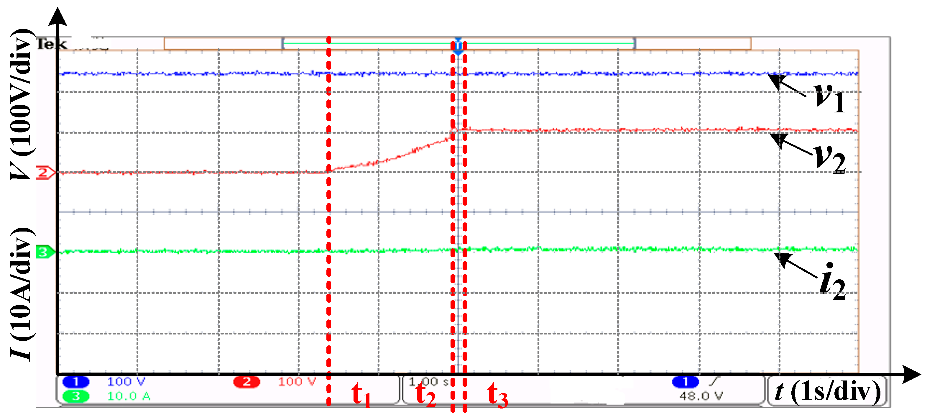
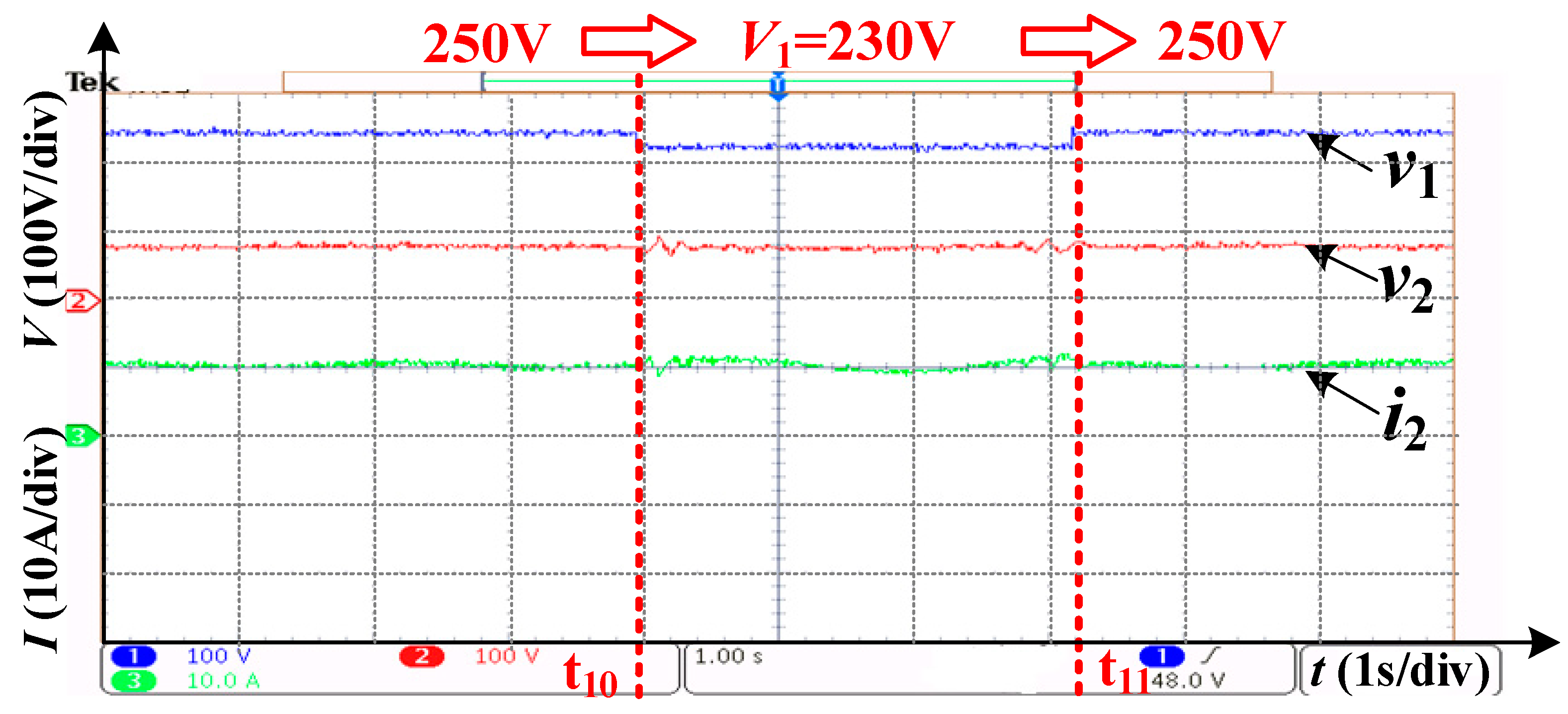
5.3. Source Perturbation Experiment

Figure 10 gives the voltages and current waveforms of the DAB converter in a source perturbation experiment. At first, the source voltage is 250 V, and the secondary voltage is stable at 80 V with a 1 kW CPL. At the time t10, the source voltage drops to 230 V suddenly, and the secondary voltage remains stable with slight fluctuation. At the time t11, the source voltage restores to 250 V suddenly, and the secondary voltage also remains stable at the same time. This shows that the DAB converter can stabilize the secondary voltage with large source perturbation.

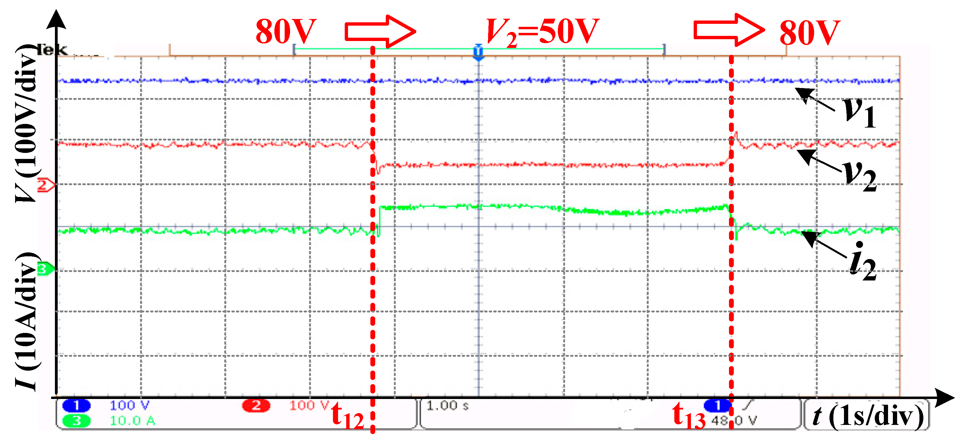
5.4. Voltage Reference Step Experiment

Figure 11 gives the voltages and current waveforms of the DAB converter in the voltage reference step change experiment. At first, the source voltage is 250 V, and the secondary voltage is stable at 80 V with a 1 kW CPL. At the time t12, the reference voltage is set to 50 V suddenly, the voltage tracks the reference quickly, and the current increases correspondingly. At the time t13, the reference voltage is reset to 80 V suddenly, the voltage also tracks the reference quickly, and the current also decreases correspondingly. This shows that the DAB converter has a good dynamic response characteristic.

6. Conclusions

This paper develops a practical PBC controller based on the EL model for the DAB converter. This controller is validated under different conditions, including source perturbation, CPL perturbation, and reference step change. Compared with the previous approaches, the proposed approach has a definite physical meaning which is deduced from Kirchhoff’s law, and it is more suitable for voltage-stabilizing control scenarios. The results, which are obtained from simulations and low-power prototype experiments, prove its feasibility and good performance.

Author Contributions

Data curation, Y.Z. (Yajing Zhang) and J.W.; Funding acquisition, Y.Z. (Yuming Zhao); Investigation, X.W.; Writing—original draft, J.L. All authors have read and agreed to the published version of the manuscript.

Funding

This research was funded by The Beijing Natural Science Foundation Program of China (no. 3202010), Key Science and Technology Projects of China Southern Power Grid Corporation (no. 090000KK52210132) and The National Natural Science Foundation of China (no. 52107176, 52237008).

Conflicts of Interest

The authors declare no conflict of interest.

References

  1. Walter, J.; De Doncker, R. High-power galvanically isolated DC/DC converter topology for future automobiles. In Proceedings of the IEEE 34th Annual Conference on Power Electronics Specialist, Acapulco, Mexico, 15–19 June 2003; Volume 1, pp. 27–32. [Google Scholar]
  2. Kheraluwala, M.; De Doncker, R. Single phase unity power factor control for dual active bridge converter. In Proceedings of the IEEE Industry Applications Conference 28th IAS Annual Meeting, Toronto, ON, Canada, 2–8 October 1993; Volume 2, pp. 909–916. [Google Scholar]
  3. De Doncker, R.W.; Divan, D.M.; Kheraluwala, M.H. A three phase soft switched high power density DC/DC converter for high power applications. IEEE Trans. Indus. Appl. 1988, 27, 63–73. [Google Scholar] [CrossRef]
  4. Zhao, B.; Song, Q.; Liu, W.; Sun, Y. Overview of dual-active-bridge isolated bidirectional dc–dc converter for high-frequency-link power-conversion system. IEEE Trans. Power Electron. 2014, 29, 4091–4106. [Google Scholar] [CrossRef]
  5. Zhao, B.; Song, Q.; Liu, W.; Sun, Y. Dead-time effect of the high-frequency isolated bidirectional full-bridge dc–dc converter: Comprehensive theoretical analysis and experimental verification. IEEE Trans. Power Electron. 2014, 29, 1667–1680. [Google Scholar] [CrossRef]
  6. López-Rodríguez, K.; Escobar-Mejía, A.; Piedrahita-Echavarria, E.Y.; Gil-González, W. Passivity-Based Current Control of a Du-al-Active Bridge to Improve the Dynamic Response of a Solid-State Transformer During Power and Voltage Variations. In Proceedings of the IEEE 11th International Symposium on Power Electronics for Distributed Generation Systems (PEDG), Dubrovnik, Croatia, 28 September–1 October 2020; pp. 230–235. [Google Scholar]
  7. Cupelli, M.; Zhu, L.; Monti, A. Why ideal constant power loads are not the worst case condition from a control stand-point. IEEE Trans. Smart Grid 2015, 6, 2596–2606. [Google Scholar] [CrossRef]
  8. Emadi, A.; Khaligh, A.; Rivetta, C.H.; Williamson, G.A. Constant power loads and negative impedance instability in automotive systems: Definition modelling stability and control of power electronic converters and motor drives. IEEE Trans. Veh. Technol. 2006, 55, 1112–1125. [Google Scholar] [CrossRef]
  9. Martinez-Lopez, M.; Moreno-Valenzuela, J.; He, W. A robust nonlinear PI-type controller for the DC–DC buck–boost power converter. ISA Trans. 2022; in press. [Google Scholar] [CrossRef]
  10. Bobtsov, A.; Ortega, R.; Nikolaev, N.; He, W. A globally stable practically implementable PI passivity-based controller for switched power converters. arXiv 2020, arXiv:2005.01671. [Google Scholar] [CrossRef]
  11. Ai, X.; Zuo, D.; Zhang, Y. Modeling and Simulation of Dual-Active-Bridge Based on PI Control. J. Phys. Conf. Ser. 2022, 2221, 012007. [Google Scholar] [CrossRef]
  12. Qin, H.; Kimball, J.W. Generalized Average Modeling of Dual Active Bridge DC–DC Converter. IEEE Trans. Power Electron. 2011, 27, 2078–2084. [Google Scholar] [CrossRef]
  13. Li, H.; Peng, F.Z.; Lawler, J.S. A natural zvs medium-power bidirectional dc-dc converter with minimum number of devices. IEEE Trans. Ind. Appl. 2003, 39, 525–535. [Google Scholar]
  14. Krismer, F.; Kolar, J.W. Closed form solution for minimum conduction loss modulation of dab converters. IEEE Trans. Power Electron. 2011, 27, 174–188. [Google Scholar] [CrossRef]
  15. Krismer, F.; Kolar, J.W. Accurate small-signal model for the digital control of an automotive bidirectional dual active bridge. IEEE Trans. Power Electron. 2009, 24, 2756–2768. [Google Scholar] [CrossRef]
  16. Cardozo DD, M.; Balda, J.C.; Trowler, D.; Mantooth, H.A. Novel nonlinear control of dual active bridge using simplified converter model. In Proceedings of the 25th IEEE Annual Applied Power Electronics Conference and Exposition (APEC), Palm Springs, CA, USA, 21–25 February 2010; p. 7. [Google Scholar]
  17. Phattanasak, M.; Gavagsaz-Ghoachani, R.; Martin, J.P.; Pierfederici, S.; Davat, B. Flatness based control of an isolated three-port bidirectional dc-dc converter for a fuel cell hybrid source. In Proceedings of the IEEE Energy Conversion Congress and Exposition (ECCE), Phoenix, AZ, USA, 17–22 September 2011; pp. 977–984. [Google Scholar]
  18. Phattanasak, M.; Gavagsaz-Ghoachani, R.; Martin, J.-P.; Nahid-Mobarakeh, B.; Pierfederici, S.; Davat, B. Comparison of two nonlinear control strategies for a hybrid source system using an isolated three-port bidirectional DC-DC converter. In Proceedings of the 2011 IEEE Vehicle Power and Propulsion Conference, Chicago, IL, USA, 6–9 September 2011; pp. 1–6. [Google Scholar]
  19. Zhang, H.; Li, Y.; Li, Z.; Zhao, C.; Gao, F.; Hu, Y.; Luo, L.; Luan, K.; Wang, P. Model predictive control of input-series output-parallel dual active bridge converters based DC transformer. IET Power Electron. 2020, 13, 1144–1152. [Google Scholar] [CrossRef]
  20. Xiao, Z.; Lei, W.; Gao, G.; Cui, Y.; Kang, Q.; Wang, M. Transient Current Constraint of DAB Converter Based on Model Predictive Control. In Proceedings of the 2020 IEEE 9th International Power Electronics and Motion Control Conference (IPEMC2020-ECCE Asia), Nanjing, China, 29 November–2 December 2020; pp. 203–207. [Google Scholar]
  21. Jeung, Y.-C.; Lee, D.-C. Voltage and current regulations of bidirectional isolated dual-active-bridge DC–DC converters based on a double-integral sliding mode control. IEEE Trans. Power Electron. 2019, 34, 6937–6946. [Google Scholar] [CrossRef]
  22. Li, K.; Yang, Y.; Tan, S.-C.; Hui, R.S.-Y. Sliding-Mode-Based Direct Power Control of Dual-Active-Bridge DC-DC Converters. In Proceedings of the 2019 IEEE Applied Power Electronics Conference and Exposition (APEC), Anaheim, CA, USA, 17–21 March 2019; pp. 188–192. [Google Scholar]
  23. Song, W.; Hou, N.; Wu, M. Virtual Direct Power Control Scheme of Dual Active Bridge DC–DC Converters for Fast Dynamic Response. IEEE Trans. Power Electron. 2018, 33, 1750–1759. [Google Scholar] [CrossRef]
  24. Xu, Q.; Vafamand, N.; Chen, L.; Dragicevic, T.; Xie, L.; Blaabjerg, F. Review on Advanced Control Technologies for Bidirectional DC/DC Converters in DC Microgrids. IEEE J. Emerg. Sel. Top. Power Electron. 2020, 9, 1205–1221. [Google Scholar] [CrossRef]
  25. Ortega, R.; van der Schaft, A.; Maschke, B.; Escobar, G. Interconnection and damping assignment passivity-based control of port-controlled Hamiltonian systems. Automatica 2002, 38, 585–596. [Google Scholar] [CrossRef]
  26. Li, J.; Lv, X.; Zhao, B.; Zhang, Y.; Zhang, Q.; Wang, J. Research on Passivity Based Control Strategy of Power Conversion System used in the Ener-gy Storage System. IET Power Electron. 2019, 12, 392–399. [Google Scholar] [CrossRef]
  27. Li, J.; Wang, M.; Zhao, Y.; Wang, J.; Yang, D.; Lv, X. Passivity-based control of the hybrid rectifier for medium and high-power application. IET Power Electron. 2019, 12, 4070–4078. [Google Scholar] [CrossRef]
  28. Yuanpeng FE, N.G.; Jiuhe WA, N.G.; Jianguo, L.I. Control strategy of Vienna rectifier with LCL filter under weak grid conditions. Power Gener. Technol. 2019, 40, 286–293. [Google Scholar]
  29. Biel, D.; Scherpen, J.M.A. Passivity-based control of active and reactive power in single-phase PV inverters. In Proceedings of the 2017 IEEE 26th International Symposium on Industrial Electronics (ISIE), Edinburgh, UK, 19–21 June 2017. [Google Scholar]
  30. Liu, G.; Wang, W.; Wang, W.; Zhu, K. Power Feedforward Method for Passivity-based Grid-connected PV Inverter in Weak Grids. In Proceedings of the 2018 IEEE 4th Southern Power Electronics Conference (SPEC), Singapore, 10–13 December 2018; pp. 1–6. [Google Scholar]
  31. Gui, Y.; Kim, W.; Chung, C.C. Passivity-Based Control With Nonlinear Damping for Type 2 STATCOM Systems. IEEE Trans. Power Syst. 2016, 31, 2824–2833. [Google Scholar] [CrossRef]
  32. Jiang, Y.; Qin, C.; Xing, X.; Li, X.; Zhang, C. A Hybrid Passivity-Based Control Strategy for Three-Level T-Type Inverter in LVRT Operation. IEEE J. Emerg. Sel. Top. Power Electron. 2019, 8, 4009–4024. [Google Scholar] [CrossRef]
  33. Zhao, J.; Wu, W.; Gao, N.; Wang, H.; Chung, H.; Blaabjerg, F. Combining Passivity-Based Control with Active Damping to Improve Stability of LCL Filtered Grid-Connected Voltage Source Inverter. In Proceedings of the 2018 IEEE International Power Electronics and Application Conference and Exposition (PEAC), Shenzhen, China, 4–7 November 2018; pp. 1–6. [Google Scholar]
  34. Meshram, R.V.; Bhagwat, M.; Khade, S.; Wagh, S.R.; Stankovic, A.M.; Singh, N.M. Port-Controlled Phasor Hamiltonian Modeling and IDAPBC Control of Solid-State Transformer. IEEE Trans. Control Syst. Technol. 2017, 27, 161–174. [Google Scholar] [CrossRef]
  35. Cupelli, M.; Gurumurthy, S.K.; Bhanderi, S.K.; Yang, Z.; Joebges, P.; Monti, A.; De Doncker, R.W. Port Controlled Hamiltonian Modeling and IDA-PBC Control of Dual Active Bridge Converters for DC Microgrids. IEEE Trans. Ind. Electron. 2019, 66, 9065–9075. [Google Scholar] [CrossRef]
  36. Cupelli, M.; Bhanderi, S.K.; Gurumurthy, S.K.; Monti, A. Port—Hamiltonian Modelling and Control of Single Phase DAB Based MVDC Shipboard Power System. In Proceedings of the IECON 2018—44th Annual Conference of the IEEE Industrial Electronics Society, Washington, DC, USA, 21–23 October 2018; pp. 3437–3444. [Google Scholar]
Figure 1. The DAB topology.
Energies 15 06685 g001
Figure 2. The PBC control diagram of the DAB converter.
Energies 15 06685 g002
Figure 3. CPL simulation model.
Energies 15 06685 g003
Figure 4. Waveforms in CPL perturbation simulation.
Energies 15 06685 g004
Figure 5. Waveforms in source perturbation simulation.
Energies 15 06685 g005
Figure 6. Waveforms in reference step simulation.
Energies 15 06685 g006
Figure 7. The DAB converter prototype.
Energies 15 06685 g007
Figure 8. Waveforms in starting experiment.
Energies 15 06685 g008
Figure 9. Waveforms in CPL perturbation experiment. (a) positive CPL load. (b) negative CPL load.
Energies 15 06685 g009
Figure 10. Waveforms in source perturbation experiment.
Energies 15 06685 g010
Figure 11. Waveforms in voltage reference step experiment.
Energies 15 06685 g011
Table 1. Main parameters of DAB converter.
ParametersValue
1DC voltage v1 (V)750
2capacitance C1 (µF)2200
3resistance R1 (Ω)100 × 103
4voltage v2 (V)375
5capacitance C2 (µF)2200
6resistance R2 (Ω)100 × 103
7inductance L1 (µH)200
8HF transformer’s turn ratio750:375
9DAB switching frequency (kHz)10
10damping coefficient g223.2
11proportional coefficient kp0.12
12integral coefficient ki0.25
Table 2. Main parameters of DAB converter prototype.
ParametersValue
1DC voltage v1 (V)300
2capacitance C1 (µF)1360
3resistance R1 (Ω)200 × 103
4voltage v2 (V)150
5capacitance C2 (µF)5440
6resistance R2 (Ω)100 × 103
7inductance L1 (µH)156
8HF transformer’s turn ratio300:150
9DAB switching frequency (kHz)20
10damping coefficient g2213
Publisher’s Note: MDPI stays neutral with regard to jurisdictional claims in published maps and institutional affiliations.

