Article

DC-Link Voltage Stability Analysis of Grid-Tied Converters Using DC Impedance Models

by
Ravi Kumar Gaddala
,
Mriganka Ghosh Majumder
and
Kaushik Rajashekara
*
Department of Electrical and Computer Engineering, University of Houston, Houston, TX 77204, USA
*
Author to whom correspondence should be addressed.
Energies 2022, 15(17), 6247; https://doi.org/10.3390/en15176247
Submission received: 16 June 2022 / Revised: 22 August 2022 / Accepted: 23 August 2022 / Published: 27 August 2022

Abstract

:
With the integration of renewable energy sources into the power grid, a number of power electronic converters need to be connected together in parallel. Due to this interconnection among the power converters with a common DC bus, the equivalent impedance of the DC network, i.e., DC network impedance (DCNI) of these parallel converters, may vary and can cause oscillations in the DC link voltage (DCLV). In the literature, impedance models of grid-tied converters (GCs) based on the AC side are well reported without including these variations in DCNI. In addition, the dynamics of a phase-locked loop (PLL) play a significant role in GC system stability. To evaluate these stability issues, this paper proposes small signal impedance models viewing from the DC side of a three-phase GC operating under different control modes considering the PLL dynamics and the DCNI variations. Using the proposed DC impedance models (DCIM), DCLV stability analysis is evaluated for a GC. It is verified through bode plots that the interaction between the proposed DCIM and DCNI leads to unstable operation of the closed-loop converter near the PLL bandwidth when the phase difference between DCIM and DCNI is more than 180 degrees. Finally, the analytically developed models are validated using hardware in-the-loop (HIL) testing.

1. Introduction

The voltage source inverters (VSIs) are extensively used for integrating renewable energy sources with the grid. As more of these converters are integrated, there may be stability issues due to the interactions between the power converters and the utility grid [1]. These stability problems are reported in the literature for various applications, such as the integration of solar PV with grid-connected inverters, offshore wind turbines with high-voltage direct-current transmission [2,3], etc. In order to analyze the stability of grid-connected converters, small-signal stability approaches can be divided into two types, namely state-space modeling [4,5] and small signal impedance modeling [6]. As a result of the development of impedance measurement systems, impedance-based techniques are becoming increasingly important in comparison to state-space techniques. A further advantage of impedance-based models is that they do not require repeated system modeling, and they can provide the frequency domain response for the purposes of determining the stability of the system. The block diagram of a typical DC–AC interface for connecting a DC and AC network from a small signal impedance perspective is shown in Figure 1a. From Figure 1a, an impedance-based stability analysis of a grid-connected inverter can be analyzed in two ways. According to the first approach [7] which is shown in Figure 1b, if the ratio of Z i n / Z d c satisfies the Nyquist stability criteria, then the system is stable, where Z d c is the equivalent DC impedance of the total system looking across the DC link to the AC grid side as marked in Figure 1a (it also includes the impedance of the DC capacitor C d c ). In the other approach [8], looking from the AC side which is depicted in Figure 1c, the system remains stable if the Z g / Z p c c ratio adheres to the Nyquist stability criteria. In this approach, the point of common coupling (PCC) impedance ( Z p c c ) is calculated by looking from the PCC terminals or AC side to the DC side.
A synchronously rotating d q frame impedance model for three-phase grid-tied converters is developed in [9] from an AC perspective. The impedance-based stability of grid-tied voltage source converters is examined by using impedance models in [10]. Modeling the impedance of three-phase voltage source converters considering the PLL dynamics and frequency locked loops for synchronizing the converter with the grid are discussed in [11]. The research reported in [9,10,11] is mainly focused on developing the impedance models and investigating the influence of control parameters, system parameters, and their variations on the stability of grid-tied converters. A unified impedance model of grid-connected converter is proposed both in α β and d q reference frames [12]. The impact of PLL and weak grid conditions on GC systems is presented in [13]. In [14], the authors pointed out that PLL is acting as a bridge for propagating phase angle information from α β to d q transformation blocks. Therefore, a recent paper [15] emphasized the importance of incorporating the PLL dynamics into the d q -frame-based impedance calculation for three-phase grid-tied voltage source converters. Thus, PLL has a significant effect on GCs. Although AC side impedance models in [12,13,14,15] are used to assess the stability of the overall system, the effect of DCNI on the system stability remains unexplored in the literature.
The impedance models based on the AC side have difficulty in incorporating DCNI variations on the system stability. A few researchers have proposed the stability analysis based on DC side impedance modeling [16,17,18,19,20,21,22,23]. In [16], based on the virtual impedance method, the DCNI is estimated in the interfaced distributed generation. In [17], it is stated that when AC networks are connected with DC networks through VSCs, the stability of the VSC can be affected significantly. Therefore, it is impossible to ignore the significance of this coupling when developing impedance models. An impedance-based approach is presented to analyze the stability of HVDC systems viewed from the DC side [18]. In [18], impedance models based on the DC side have ignored the dynamics of AC networks. In [19], modeling and analysis of VSC-based HVDC systems for DC network stability studies are discussed. However, in the analysis, the effect of grid impedance and PLL dynamics is not considered for stability analysis. In [20], impedance-based DC link voltage stability analysis is presented in both α β and d q frames. DC impedance modeling of grid-connected converters is presented in [21] considering the grid impedance. However, the DCNI between the two converters is ignored. DCIMs with L filters are proposed and DCNI effects are examined in the DCLV stability analysis of grid-tied inverters in [22]. However, the effect of DC impedance models at lower duty ratios, the dynamics of the PLL effect, and the grid impedance on system stability are not studied. In [23], grid-tied converters operating under open loop, with closed loop d q current control, and with DC link voltage control conditions are discussed based on DC side impedance models. However, stability analysis does not consider PLL dynamics. The existing models in the literature do not consider both the dynamics of PLL and DC network impedance variations in the DC link voltage stability analysis of the grid-tied converter.
Therefore, this paper presents a DC link voltage stability analysis of grid-tied converters using DC side impedance modeling considering both the dynamics of PLL and DC network impedance variations.
The main contributions of this paper are:
  • In order to assess the stability issues, this paper proposes small signal impedance models viewed from the DC side for a three-phase grid-tied converter operating under different control modes such as open loop, d q current control, and DCLV control, taking into account the dynamics of a PLL.
  • Using the proposed DC impedance models, DC-link voltage stability analysis is evaluated for a complete typical grid-tied converter, including DCNI variations.
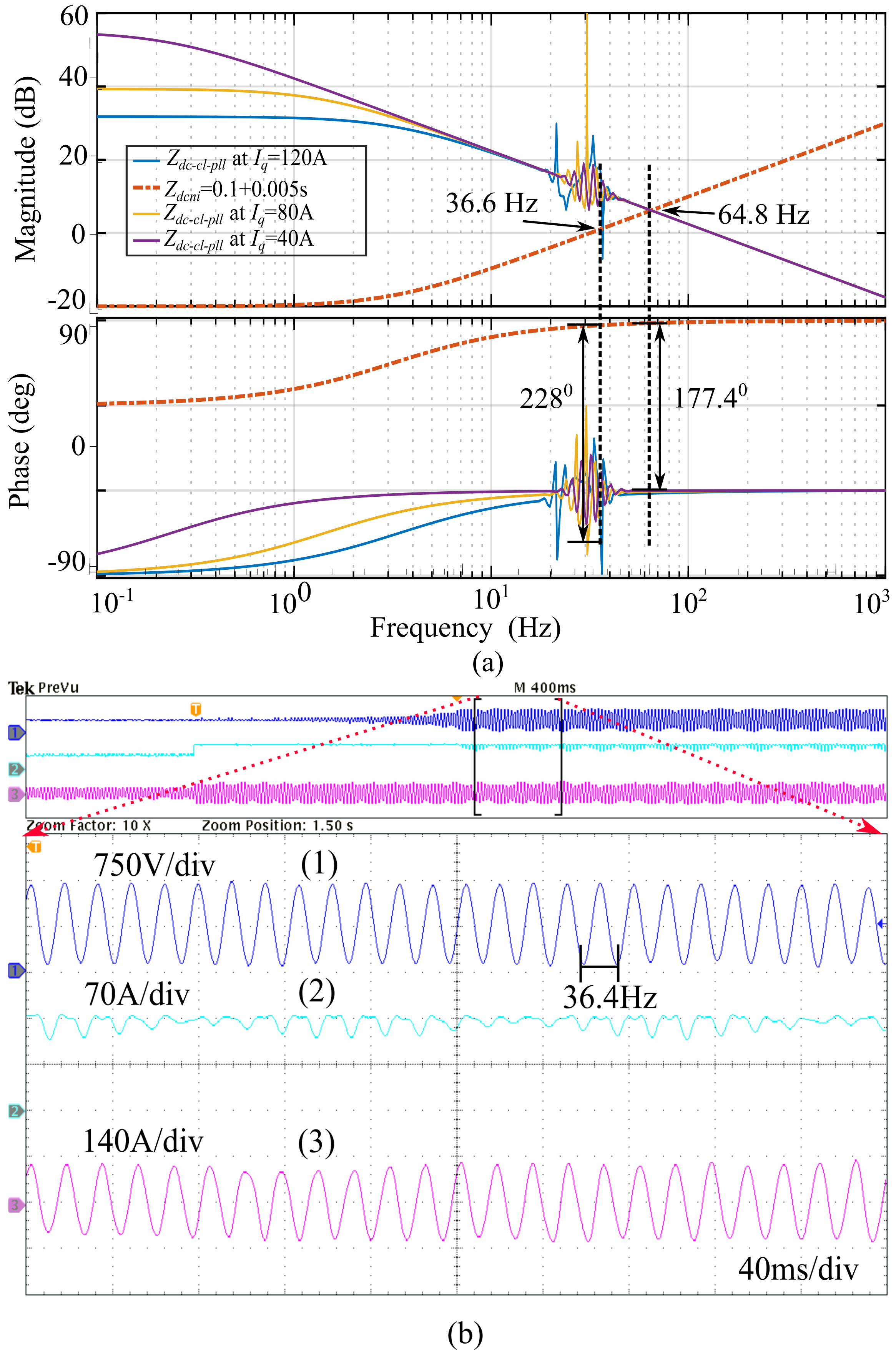
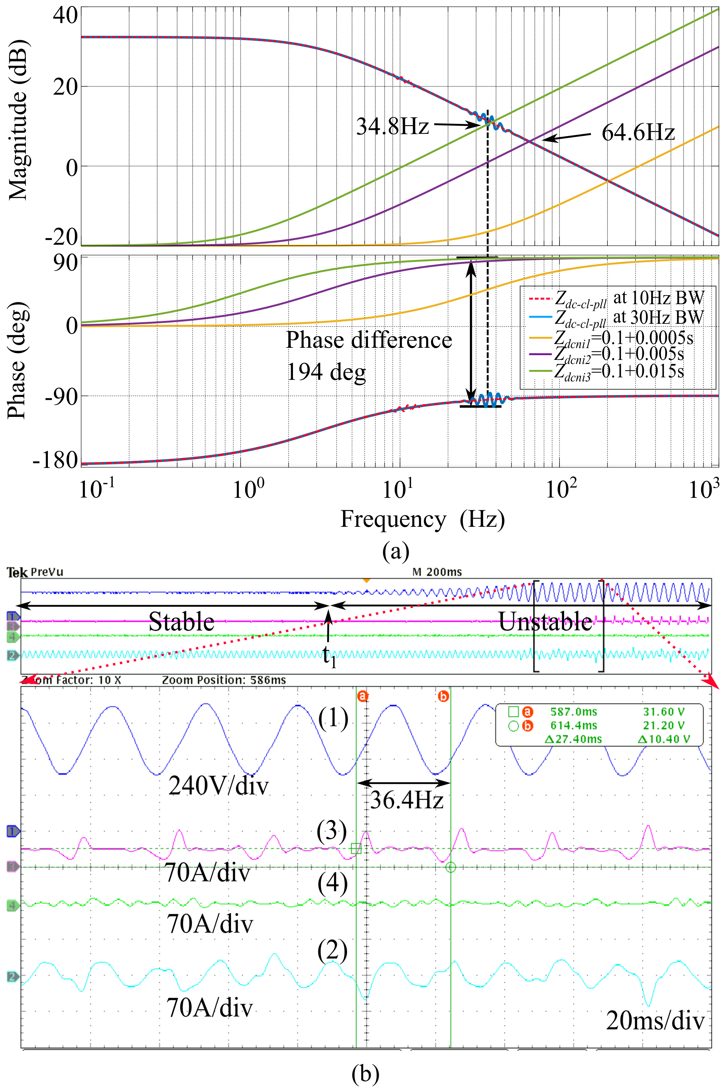
  • From the proposed models, it is observed that the closed-loop-converter is operating under unstable mode due to the interaction of DCIM and DCNI in the frequency plot closer to the PLL bandwidth.
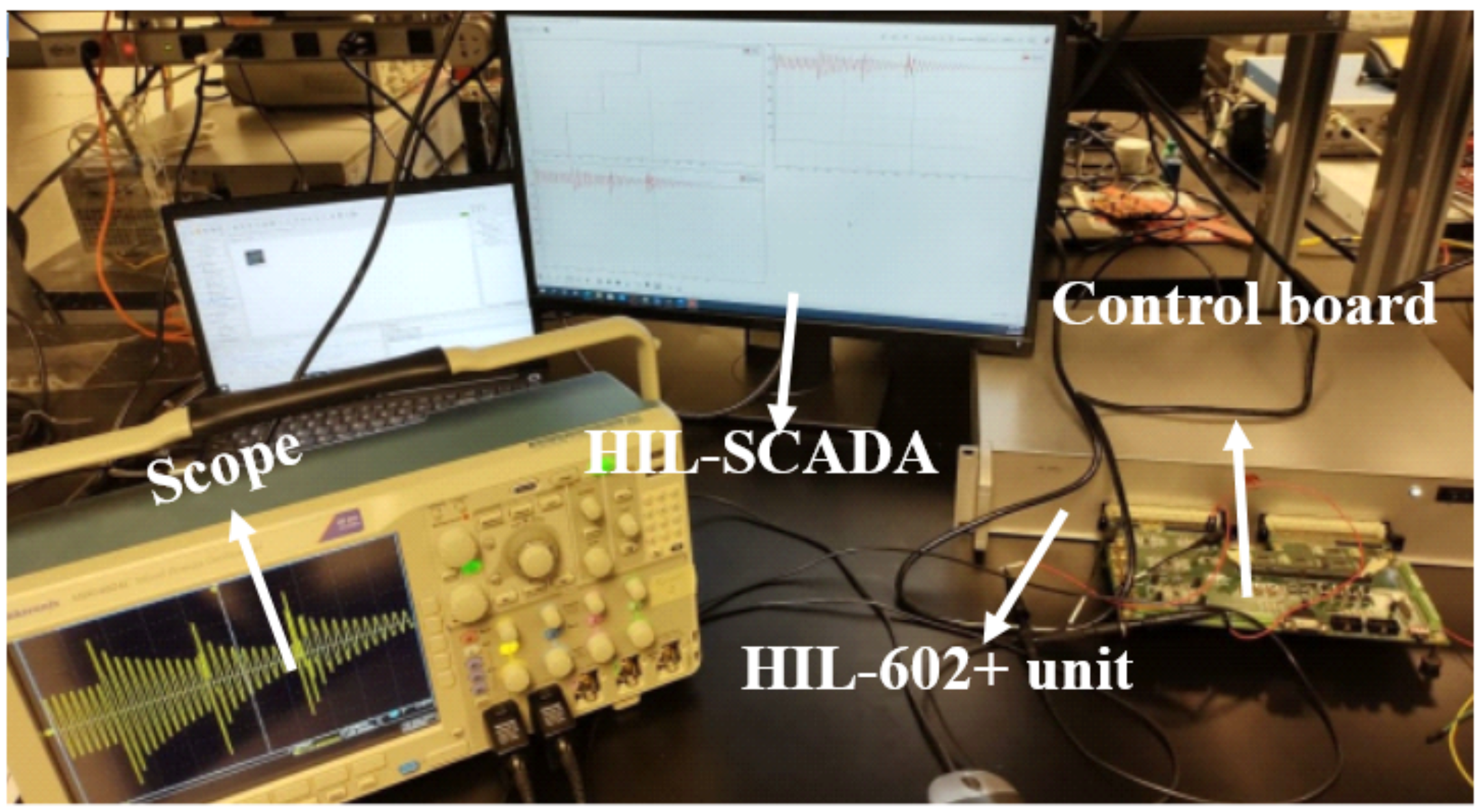
  • Finally, in order to validate the results obtained from the mathematical models, the grid-tied converter is simulated using controller HIL.
The rest of the paper is organized as follows: Section 2 introduces the configuration of the system. In Section 3, DC impedance models and small signal block diagrams are proposed for different control modes of the GCs. To determine the stability, Section 4 discusses the validation of the proposed models. Section 5 concludes by drawing conclusions.

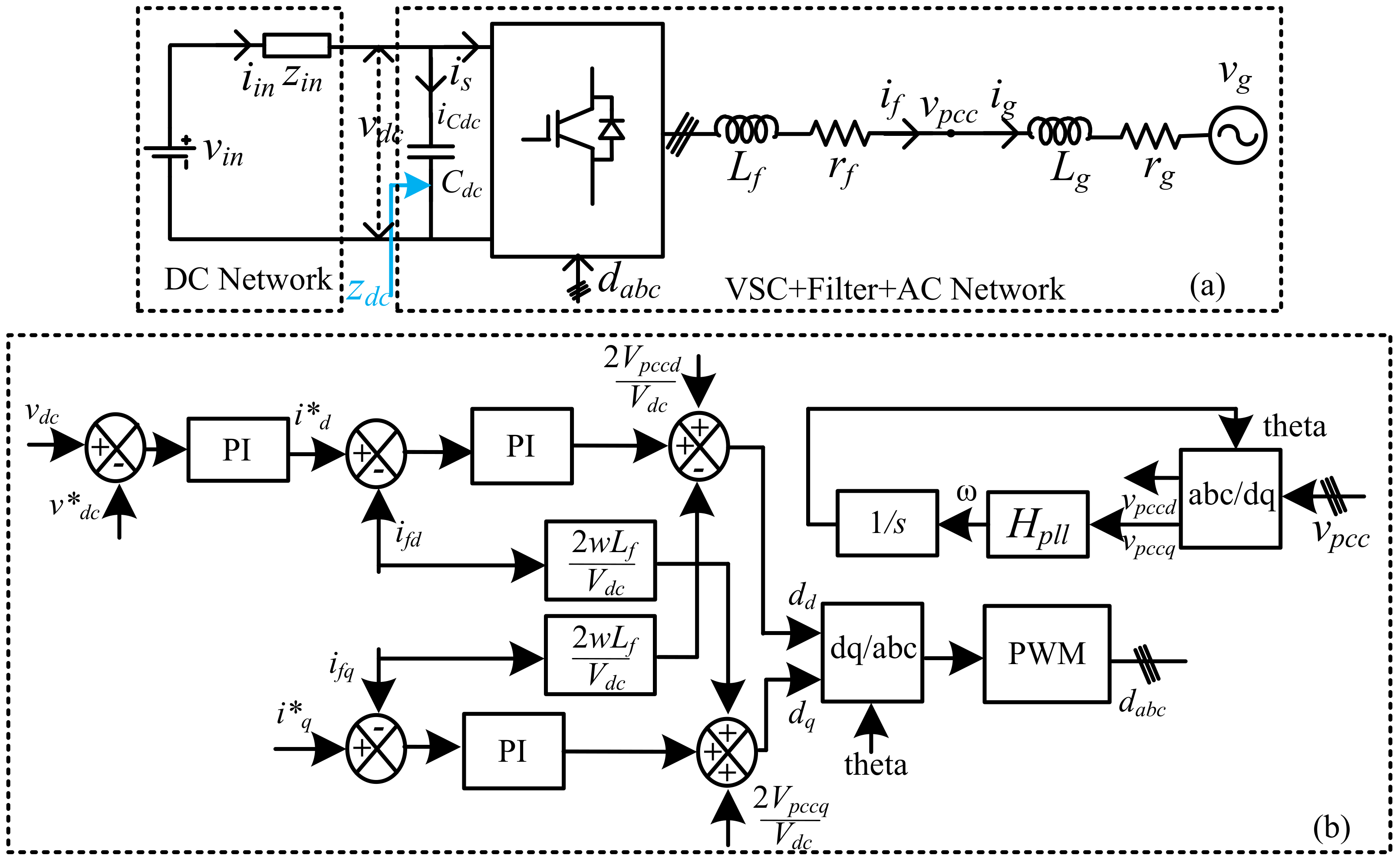
2. System Configuration

Figure 2a shows the three-phase grid-tied converter with DC and AC networks. V i n is the DC input voltage that can be obtained from the battery, solar photo voltaic cells, fuel cells, etc. Z i n is the input impedance or DC network impedance. V d c is the DC link voltage and C d c is the DC bus capacitance. Here, AC network or AC subsystems refers to the combination of grid impedance ( Z g ) and grid voltage ( V g ) . V p c c is the common coupling point voltage, and Z f is the filter impedance. The complete control system block diagram of the converter is shown in Figure 2b. For controlling the d-axis and q-axis currents, two PI controllers are used. The d-axis reference current is generated by an outer DC link voltage controller. PLL generates the required phase angle of the PCC voltage, which is used to synchronize the converter with the grid.

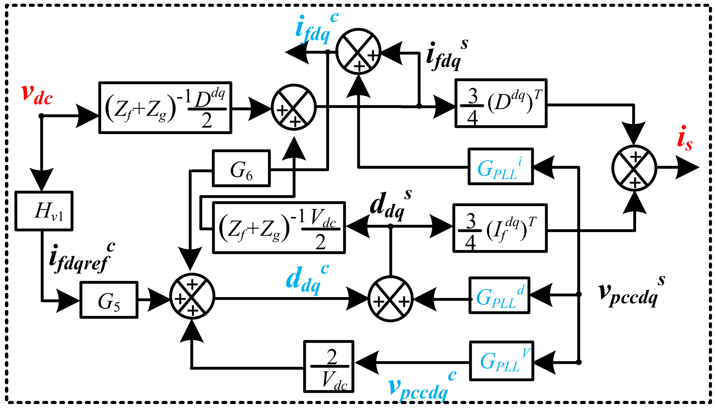
3. DC Side Impedance Modelling

Referring to Figure 1b, the DC link voltage is expressed as (1).
V d c   =   1 1   +   Z i n Z d c V i n
From (1), the stability of V d c depends on the impedance ratio between the equivalent impedance of the DC network ( Z i n ) and the DC impedance ( Z d c ) [22]. If this satisfies the Nyquist stability criterion, then the system is stable [6]. To analyze the DC link voltage stability, Bode analysis can also be used by analyzing the frequency responses of Z d c , Z i n .
The intersection frequency in the magnitude plot gives the information about oscillation or resonance frequency in the DC link voltage. A phase plot gives information about stability based on the phase difference between two impedances at the intersection frequency on the magnitude plot. If the impedance ratio phase difference is less than 180 degrees, greater than 180 degrees, and close to 180 degrees, it implies that the system is stable, unstable, and marginally stable, respectively.
For different control objectives, Z d c characteristics are different. Thus, in the following subsections, small signal DC impedance models are derived in open-loop, closed-loop d q current control, and DC link voltage control modes while considering the effect of PLL dynamics.

3.1. DC Impedance Model in an Open Loop Condition with PLL Dynamics

Small signal impedance-based model of an inverter in open-loop condition with PLL is shown in Figure 3. By using KCL from Figure 2a, the Equations (2) and (3) are expressed in the abc frame. Using the park transformation, abc frame quantities are converted to d q frame quantities, which are aligned 90 degrees behind the phase a-axis.
V d c 2 D a D b D c   =   s L f   +   r f 0 0 0 s L f   +   r f 0 0 0 s L f   +   r f i f a i f b i f c   +   v p c c a v p c c b v p c c c
v p c c a v p c c b v p c c c   =   s L g   +   r g 0 0 0 s L g   +   r g 0 0 0 s L g   +   r g i f a i f b i f c   +   v p c c a v p c c b v p c c c
(4) and (5) are representations of (2) and (3) in the d q frame. The small signal variables are denoted by a superscript ∧ in the following equations. Here, , ( y d q ) T = [ y d y q ], y = I f , D and ( y ^ d q ) T = [ y ^ d y ^ q ], y ^   =   v ^ p c c , i ^ f , i ^ g , d ^ , q ^ , where v ^ d c , i ^ i n , i ^ s are state variables.
1 2 D d q v ^ d c   +   1 2 d ^ d q V d c   =   Z f i ^ f d q   +   v ^ p c c d q
v ^ p c c d q   =   Z g i ^ g d q   +   v ^ g d q
Grid voltage is assumed to be ideal, so v ^ g d q = 0. Then, (5) can be re-written as (6). The expressions for the coefficients of filter impedance and grid impedance Z f and Z g are given in (7) and (8).
v ^ p c c d q   =   Z g i ^ g d q
Z f   =   s L f   +   r f ω L f ω L f s L f   +   r f
Z g   =   s L g   +   r g ω L g ω L g s L g   +   r g
The inverter input current is represented as a function of duty ratio, and the inverter output current can be expressed as (9). By applying KCL on the DC capacitance node point, (10) is obtained.
i ^ s   =   3 4 ( I f d q ) T d ^ d q   +   ( D d q ) T i ^ f d q
C d c s v ^ d c   =   i ^ i n     i ^ s
A PLL is used to synchronize the converter with the grid by regulating the q-axis PCC voltage. During steady state operation, the PLL angle and actual PCC voltage angle are the same. However, both angles are different when the PCC voltage fluctuates during transient operation. Due to this, the inverter has two d q -frames, namely, one is the system d q -frame and the other one is the control d q -frame [9]. The superscript ‘s’ and ‘c’ in the equations represent the system and control frame, respectively. The relations for duty cycle, grid current, PCC voltage are given in (11)–(16).
d ^ d q s   =   G PLL d v ^ p c c d q s   +   d ^ d q c
i ^ f d q c   =   G PLL i v ^ p c c d q s   +   i ^ f d q s
v ^ p c c d q c   =   G PLL v v ^ p c c d q s
G PLL d   =   0 D q G P L L 0 D d G P L L
G PLL i   =   0 I q G P L L 0 I d G P L L
G PLL v   =   1 V q G P L L 0 1 V d G P L L
In open loop condition, d ^ d q c   =   0 , which can be substituted in (11) and the modified equation is given in (17).
d ^ d q s   =   G PLL d v ^ p c c d q s
By substituting (6) in (17), the following equation is given in (18).
d ^ d q s   =   G PLL d Z g i ^ g d q
Using (4) and (6), (19) is obtained.
1 2 D d q v ^ d c   +   1 2 d ^ d q V d c   =   ( Z f   +   Z g ) i ^ f d q
By using (18) and (19), the modified expression is given in (20), and the equation for i ^ f d q is written in terms of v ^ d c is given in (21).
1 2 D d q v ^ d c   +   1 2 G PLL d Z g i ^ f d q V d c   =   ( Z f   +   Z g ) i ^ f d q
i ^ f d q   =   [ ( Z f   +   Z g V d c 2 G PLL d Z g ) 1 1 2 D d q ] v ^ d c
By substituting (18) and (21) in (9), i ^ s is determined and given in (22).
i ^ s   =   ( 3 4 [ ( I f d q ) T G PLL d Z g   +   ( D d q ) T ] ( Z g   +   Z f     V d c 2 G PLL d Z g ) 1 1 2 D d q ) v ^ d c
Finally by using (10) and (22), the DC impedance model in an open loop condition while considering the effect of PLL dynamics is given in (23).
Z d c o l p l l   =   v ^ d c i ^ i n   =   1 C d c s   +   ( 3 4 [ ( I f d q ) T G PLL d Z g   +   ( D d q ) T ] ( Z g   +   Z f     V d c 2 G PLL d Z g ) 1 1 2 D d q )

3.2. DC Impedance Model of GCs under Closed Loop Current Control Mode Considering PLL Dynamics

An inner current controller is implemented to regulate the d and q axis currents. Based on the control block diagram shown in Figure 2b, the small signal equation is represented in the d q frame for a grid-tied converter operating in a closed loop d q current control is given by (24) and the corresponding block diagram is shown in Figure 4.
d ^ d q c   =   G 5 i ^ f d q r e f c   +   G 6 i ^ f d q c   +   2 V d c v ^ p c c d q c
where the expressions for G 5 , G 6 , G i are given by (25)
G 5   =   G i 0 0 G i , G 6   =   G i ω L i 2 V d c ω L i 2 V d c G i ,
G i   =   k p i   +   K i i s
Using (2)–(24) expressions, the DC impedance model expression is obtained in the case of a current controller while considering the effect of PLL dynamics and it is given by (26). The expressions of M 3 , G PLL 1 , and M 4 are given in (27), (28), and (29) respectively.
Z d c     c l     p l l   =   v ^ d c i ^ i n   =   1 C d c s   +   3 4 [ ( D d q ) T   +   ( I f d q ) T M 3 ] ( M 4 ) 1 1 2 D d q
M 3   =   ( G PLL 1 Z g   +   G 6 )
G PLL 1   =   G PLL d   +   G 6 G PLL i   +   2 V d c G PLL v
M 4 = ( Z g   +   Z f     V d c 2 M 3 )

3.3. DC Impedance Model of GCs under DCLV Control Mode Considering PLL Dynamics

The small signal impedance-based block diagram for DC bus voltage control mode with PLL is represented in Figure 5. The regulation of DC link bus voltage becomes important to maintain the power balance, especially when DC loads are connected to DC bus. The expression of i ^ f d q r e f in terms of v ^ d c is given in (30) and where H v 1 is given in (31).
i ^ f d q r e f   =   H v 1 v ^ d c
H v 1   =   k p v   +   K i v s 0
M 5   =   ( 1 2 D d q   +   1 2 G 5 H v 1 V d c )
Finally, by using (2)–(20), (24), (30) and (31), the DC impedance model expression is obtained in the case of a DCLV controller considering the effect of PLL dynamics and is given by (33), and the expression for M 5 is given in (32).
Z d c v l p l l   =   v ^ d c i ^ i n   =   1 C d c s   +   ( 3 4 { [ ( D d q ) T   +   ( I f d q ) T M 3 ] ( M 4 ) 1 M 5 }   +   3 4 { ( I f d q ) T G 5 H v 1 } )

4. Results and Discussions

Bode plot analysis is used to analyze the proposed impedance models. Table 1 shows the parameters of the system used in this study. The Typhoon controller hardware-in-the-loop is used to validate the proposed impedance models and the Typhoon HIL testbed is shown in Figure 6.

4.1. DC Impedance-Based Stability Analysis in an Open Loop Condition with PLL Dynamics

A Bode plot for three different input impedances Z d c n i 1 , Z d c n i 2 , and Z d c n i 3 , and the derived Z d c o l p l l in (22) for fixed duty ratio of d = 0.11 is shown in Figure 7a.
From Figure 7a, the magnitude plot shows different DC network impedances intersecting at different frequencies on the open loop DC impedance ( Z d c o l p l l ). By examining the Bode plot, it is clear that the intersection frequency of two impedances is ( Z d c o l p l l , Z d c n i 1 ) is the same as the frequency observed from the DC side, which is the resonance frequency (28.8 Hz when L i n = 25 mH, C d c = 1200 μ F) of input L i n and C d c filter. Further, HIL tests have been conducted to validate the derived models, as shown in Figure 7b. From Figure 7b, it observed that the oscillation frequency in the DC link voltage waveform is 29.32 Hz. Therefore, proposed impedance models are validated. In addition, when the duty ratio d = 0.8, oscillations are not due to the resonance on the DC side but due to the impedance mismatch between the DC network impedance and open loop DC impedance. Hence, it is concluded that the frequency of oscillations in the DCLV depends on the operating point of the converter in open loop conditions.

4.2. DC Impedance-Based Stability Analysis of GCs under Closed Loop Current Control Mode with PLL Dynamics

The current loop controller bandwidth and PLL bandwidth are considered as 1000 Hz and 30 Hz, respectively, in this mode of operation. Using (26), the effect of variations in I q r e f on DC impedance model is plotted in Figure 8a. There are surges and dips around 30 Hz in both magnitude and phase plots of Z d c c l p l l at I q = 120 A in Figure 8a.
It is noticed that the phase plot is shifting down as I q r e f is increasing, which indicates that the converter is losing stability. A phase difference of 228 0 at 36.6 Hz is observed when I q r e f = 120 A, which results in an unstable operation of the closed loop converter under this condition. Further, the derived models are validated using the controller in the loop tests. From Figure 8a, when the current is changing from 60 A to 120 A, it was observed that I q r e f is not tracking and reaching unstable operation. Further, very high DCLV oscillations appeared across the dc link capacitance. The frequency of oscillations in the DC link voltage is noticed at 36.4 Hz. This indicates that derived models are accurate.
Further, the variations in the bandwidth of PLL on DC impedance models are investigated here. The current loop controller bandwidth and PLL bandwidth are considered as 1000 Hz and 30 Hz, respectively, in this condition. Using (26), DCIM plots are drawn with two PLL bandwidths which are at Z d c c l p l l (10 Hz) and Z d c c l p l l (30 Hz). There are surges and dips around 30 Hz in both magnitude and phase plots of Z d c c l p l l (30 Hz) in Figure 9a. Here, Z d c c l p l l (30 Hz) and Z d c n i 3 intersect at 34.8 Hz. The phase difference between the two impedances is 194 0 at that crossover frequency which indicates that the gird-tied converter is operating in an unstable mode. Additionally, HIL tests have been conducted to validate the derived models, as shown in Figure 9b. In Figure 9b, before t 1 , the converter was operating in a stable region with Z d c n i 1 . At t 1 , Z d c n i 1 is changed to Z d c n i 3 . During this period, the DCLV gradually builds up and causes unstable operation of the converter.
During the unstable region, the DCLV oscillations are noticed at 36.49 Hz, which is close to the intersection frequencies of both impedances in the Bode plot. It is concluded that, in d q current control, DCIM interacts with DCNI in and around the PLL bandwidth, which results in oscillations in the DCLV and may result in unstable operation of the converter.

4.3. DC Impedance-Based Stability Analysis of GCs under DCLV Control Mode with PLL Dynamics

By using (33), DCIM plots are drawn with two PLL bandwidths, Z d c v l p l l (10 Hz) and Z d c v l p l l (30 Hz) are shown in From Figure 10a. Here also in Figure 10a, there are surges and dips around 30 Hz and 10 Hz in both magnitude and phase plots of Z d c v l p l l (30 Hz) and Z d c v l p l l (10 Hz) respectively. From Figure 10a, Z d c v l p l l (30 Hz) and Z d c n i 3 intersect at 32.1 Hz. The phase difference between the two impedances at that intersection frequency is 198 0 , resulting in unstable operation. Further, HIL tests have been conducted to validate the derived models, as shown in Figure 10b. Before t 1 , the converter is operating under stable conditions with Z d c n i 2 . At t 1 , the impedance is changed from Z d c n i 2 to Z d c n i 3 . Then, DC link voltage is slowly building up and reaches unstable operation. During the unstable region, the DCLV oscillations are noticed at 31.7 Hz, which is close to the intersection frequencies of both impedances. It indicates that the proposed models are accurate. It is concluded that, in the case of DCLV control, DCIM interacts with DCNI around the PLL bandwidth, which result in instability of the converter.

5. Conclusions

This paper proposes small signal DC impedance models for a grid-tied converter operating in an open loop, closed loop d q current control, and DCLV control loop with consideration of PLL dynamics. It is found that in an open loop condition, DCLV oscillation frequencies are caused by DC side LC resonance when operating with lower duty ratios. Furthermore, it is noticed that both the magnitude and phase plot of DCIMs show surges and dips around the PLL bandwidth. Because of this, when DCIMs interact with DCNIs close to the PLL bandwidth, they cause oscillations in the DCLV, which results in unstable operation when using d q current control mode. Moreover, in DCLV control mode, the variations in DCNI interact with the DCIM, resulting in an unstable operation. Finally, the proposed impedance models for various control modes are verified through Bode analysis and HIL testing.

Author Contributions

Supervision, K.R.; Writing—original draft, R.K.G. and M.G.M. All authors have read and agreed to the published version of the manuscript.

Funding

This research received no external funding.

Institutional Review Board Statement

Not applicable.

Informed Consent Statement

Not applicable.

Data Availability Statement

Not applicable.

Conflicts of Interest

The authors declare no conflict of interest.

Abbreviations

The following abbreviations are used in this manuscript:
DCNIDC network impedance
DCIMDC impedance model
GCgrid-tied converter
PLLphase locked loop
HILhardware in-the-loop
VSIsvoltage source inverters
DCLVDC link voltage
PCCpoint of common coupling
Z g grid impedance
Z f filter impedance
f s w switching frequency
f g grid frequency
V g grid voltage
V p c c voltage at the point of common coupling
i f or i g grid current
D a b c duty ratio to the inverter at steady state
V d c steady state DC link voltage

References

  1. Wang, X.; Blaabjerg, F.; Wu, W. Modeling and analysis of harmonic stability in an AC power-electronics-based power system. IEEE Trans. Power Electron. 2014, 29, 6421–6432. [Google Scholar] [CrossRef]
  2. Enslin, J.; Heskes, P. Harmonic interaction between a large number of distributed power inverters and the distribution network. IEEE Trans. Power Electron. 2004, 19, 1586–1593. [Google Scholar] [CrossRef]
  3. Dhua, D.; Yang, G.; Zhang, Z.; Kocewiak, Ł.H.; Timofejevs, A. Harmonic active filtering and impedance-based stability analysis in offshore wind power plants. In Proceedings of the 16th International Workshop on Large-Scale Integration of Wind Power into Power Systems as well as on Transmission Networks for Offshore Wind Power Plants, Berlin, Germany, 25–27 October 2017. [Google Scholar]
  4. Raza, M.; Prieto-Araujo, E.; Gomis-Bellmunt, O. Small-signal stability analysis of offshore AC network having multiple vsc-hvDC systems. IEEE Trans. Power Deliv. 2018, 33, 830–839. [Google Scholar] [CrossRef]
  5. Hiti, S.; Boroyevich, D.; Cuadros, C. Small-signal modeling and control of three-phase PWM converters. In Proceedings of the 1994 IEEE Industry Applications Society Annual Meeting, Denver, CO, USA, 2–6 October1994; Volume 2, pp. 1143–1150. [Google Scholar] [CrossRef]
  6. Sun, J. Impedance-based stability criterion for grid-connected in-verters. IEEE Trans. Power Electron. 2011, 26, 3075–3078. [Google Scholar] [CrossRef]
  7. Cespedes, M.; Sun, J. Impedance modeling and analysis of grid-connected voltage-source converters. IEEE Trans. Power Electron. 2014, 29, 1254–1261. [Google Scholar] [CrossRef]
  8. Shah, S.; Parsa, L. Sequence domain transfer matrix model of three-phase voltage source converters. In Proceedings of the 2016 IEEE Power and Energy Society General Meeting (PESGM), Boston, MA, USA, 17–21 July 2016; pp. 1–5. [Google Scholar] [CrossRef]
  9. Wen, B.; Boroyevich, D.; Burgos, R.; Mattavelli, P.; Shen, Z. Analysis of DQ small-signal impedance of grid-tied inverters. IEEE Trans. Power Electron. 2016, 31, 675–687. [Google Scholar] [CrossRef]
  10. Yang, Z.; Shah, C.; Chen, T.; Yu, L.; Joebges, P.; Doncker, R.W.D. Stability investigation of three-phase grid-tied PV inverter systems using impedance models. IEEE J. Emerg. Sel. Top. Power Electron. 2020, 10, 2672–2684. [Google Scholar] [CrossRef]
  11. Golestan, S.; Guerrero, J.M.; Al-Turki, Y.; Vasquez, J.C.; Abusorrah, A.M. Impedance Modeling of Three-Phase Grid-Connected Voltage Source Converters with Frequency-Locked-Loop-Based Synchronization Algorithms. IEEE Trans. Power Electron. 2022, 37, 4511–4525. [Google Scholar] [CrossRef]
  12. Wang, X.; Harnefors, L.; Blaabjerg, F. Unified impedance model of grid-connected voltage-source converters. IEEE Trans. Power Electron. 2018, 33, 1775–1787. [Google Scholar] [CrossRef]
  13. Zhang, X.; Xia, D.; Fu, Z.; Wang, G.; Xu, D. An improved feed-forward control method considering PLL dynamics to improve weak grid stability of grid-connected inverters. IEEE Trans. Ind. 2018, 54, 5143–5151. [Google Scholar] [CrossRef]
  14. Wen, B.; Boroyevich, D.; Mattavelli, P.; Shen, Z.; Burgos, R. Influence of phase-locked loop on input admittance of three-phase voltage-source converters. In Proceedings of the 2013 Twenty-Eighth Annual IEEE Applied Power Electronics Conference and Exposition (APEC), Long Beach, CA, USA, 17–21 March 2013; pp. 897–904. [Google Scholar] [CrossRef]
  15. Golestan, S.; Ebrahimzadeh, E.; Wen, B.; Guerrero, J.M.; Vasquez, J.C. dq-Frame Impedance Modeling of Three-Phase Grid-Tied Voltage Source Converters Equipped with Advanced PLLs. IEEE Trans. Power Electron. 2021, 36, 3524–3539. [Google Scholar] [CrossRef]
  16. He, J.; Li, Y.W. Analysis, design, and implementation of virtual impedance for power electronics interfaced distributed generation. IEEE Trans. Ind. Appl. 2011, 47, 2525–2538. [Google Scholar] [CrossRef]
  17. Huang, Y.; Yuan, X.; Hu, J.; Zhou, P. Modeling of VSC connected to weak grid for stability analysis of DC-link voltage control. IEEE J. Emerg. Sel. Top. Power Electron. 2015, 3, 1193–1204. [Google Scholar] [CrossRef]
  18. Liu, H.; Shah, S.; Sun, J. An impedance-based approach to HVDC system stability analysis and control design. In Proceedings of the 2014 International Power Electronics Conference (IPEC-Hiroshima 2014—ECCE ASIA), Hiroshima, Japan, 18–21 May 2014; pp. 967–974. [Google Scholar]
  19. Pinares, G.; Bongiorno, M. Modeling and analysis of VSC-based HVDC systems for DC network stability studies. IEEE Trans. Power Deliv. 2016, 31, 848–856. [Google Scholar] [CrossRef]
  20. Lu, D.; Wang, X.; Blaabjerg, F. Impedance-based analysis of DC-link voltage dynamics in voltage-source converters. IEEE Trans. Power Electron. 2019, 34, 3973–3985. [Google Scholar] [CrossRef]
  21. Yuan, Y.; Li, L.; Yang, J.; Chen, L.; Nian, H. DC impedance modeling and stability analysis of VSC with consideration of grid impedance. In Proceedings of the 2020 IEEE/IAS Industrial and Commercial Power System Asia (ICPS Asia), Weihai, China, 13–16 July 2020; pp. 431–436. [Google Scholar] [CrossRef]
  22. Liu, J.; Tao, X.; Yu, M.; Xia, Y.; Wei, W. Impedance modeling and analysis of three-phase voltage-source converters viewing from DC side. IEEE J. Emerg. Sel. Top. Power Electron. 2020, 8, 3906–3916. [Google Scholar] [CrossRef]
  23. Gaddala, R.K.; Reddy, S.R.P.; Majumder, M.G.; Rajashekara, K.; da Fonseca Jean Marcos, L. Influence of DC Network Impedance and Control Parameters on Stability of Grid-tied Converters with LCL Filter Analyzing from DC Side. In Proceedings of the 2022 International Power Electronics Conference (IPEC-Himeji 2022—ECCE Asia), Himeji, Japan, 15–19 May 2022; pp. 127–132. [Google Scholar] [CrossRef]
Figure 1. Block diagram of (a) a typical DC to AC interface for connecting an AC network and DC network from a small signal impedance perspective, (b,c) An equivalent representation of the entire system seen from the DC side and the AC side, respectively.
Energies 15 06247 g001
Figure 2. Block diagram of (a) Three phase DC–AC converter with DC and AC networks and (b) DC link voltage controller and PLL.
Energies 15 06247 g002
Figure 3. Small signal impedance model of GC operating in open loop with PLL dynamics.
Energies 15 06247 g003
Figure 4. Small signal impedance model of GC operating in closed loop current control with consideration of PLL dynamics.
Energies 15 06247 g004
Figure 5. Small signal impedance model of GC operating in DCLV control mode with consideration of PLL dynamics.
Energies 15 06247 g005
Figure 6. Typhoon HIL testbed.
Energies 15 06247 g006
Figure 7. In open loop mode, the converter operates with d = 0.11 (a) A Bode plot shows the DCIM with various DCNIs, (b) Test result with DCNI: (1) DC link voltage, (2) Grid current.
Energies 15 06247 g007
Figure 8. The converter is operating in a closed loop d q current control mode. (a) A Bode plot shows the DCIM characteristics of various q-axis currents with DCNI, (b) test result with DCNI: (1) DC link voltage, (2) q-axis actual current, (3) Grid current.
Energies 15 06247 g008
Figure 9. The converter is operating in closed loop d q current control mode. (a) A Bode plot shows the DC impedance model characteristics with different DC network impedances, (b) test result with DCNI: (1) DC link voltage, (2) grid current, (3) d-axis actual current, (4) q-axis actual current.
Energies 15 06247 g009
Figure 10. The converter is operating in a closed loop DC link voltage control mode (a) A Bode plot shows the DCIM characteristics with various DCNIs, (b) test result with DCNI: (1) DC link voltage, (2) grid current.
Energies 15 06247 g010
Table 1. System parameter.
SymbolValue
V i n , V g r m s 750 V, 230 V
C d c 1200 μ F
L f , r f 2.6 mH, 0.77 Ω
L g , r g 1.3 mH, 0.38 Ω
f s w , f g 10 kHz, 60 Hz
Publisher’s Note: MDPI stays neutral with regard to jurisdictional claims in published maps and institutional affiliations.

