

Carbon Nanotube Fiber-Based Wearable Supercapacitors—A Review on Recent Advances


Abstract
: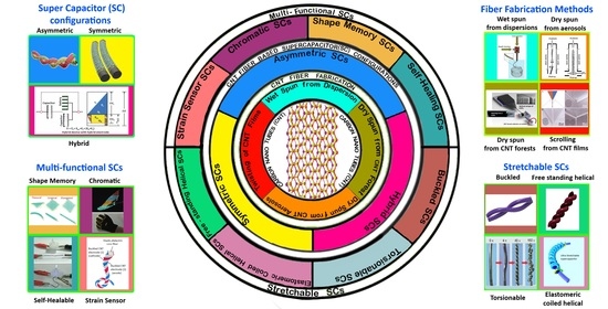
1. Introduction
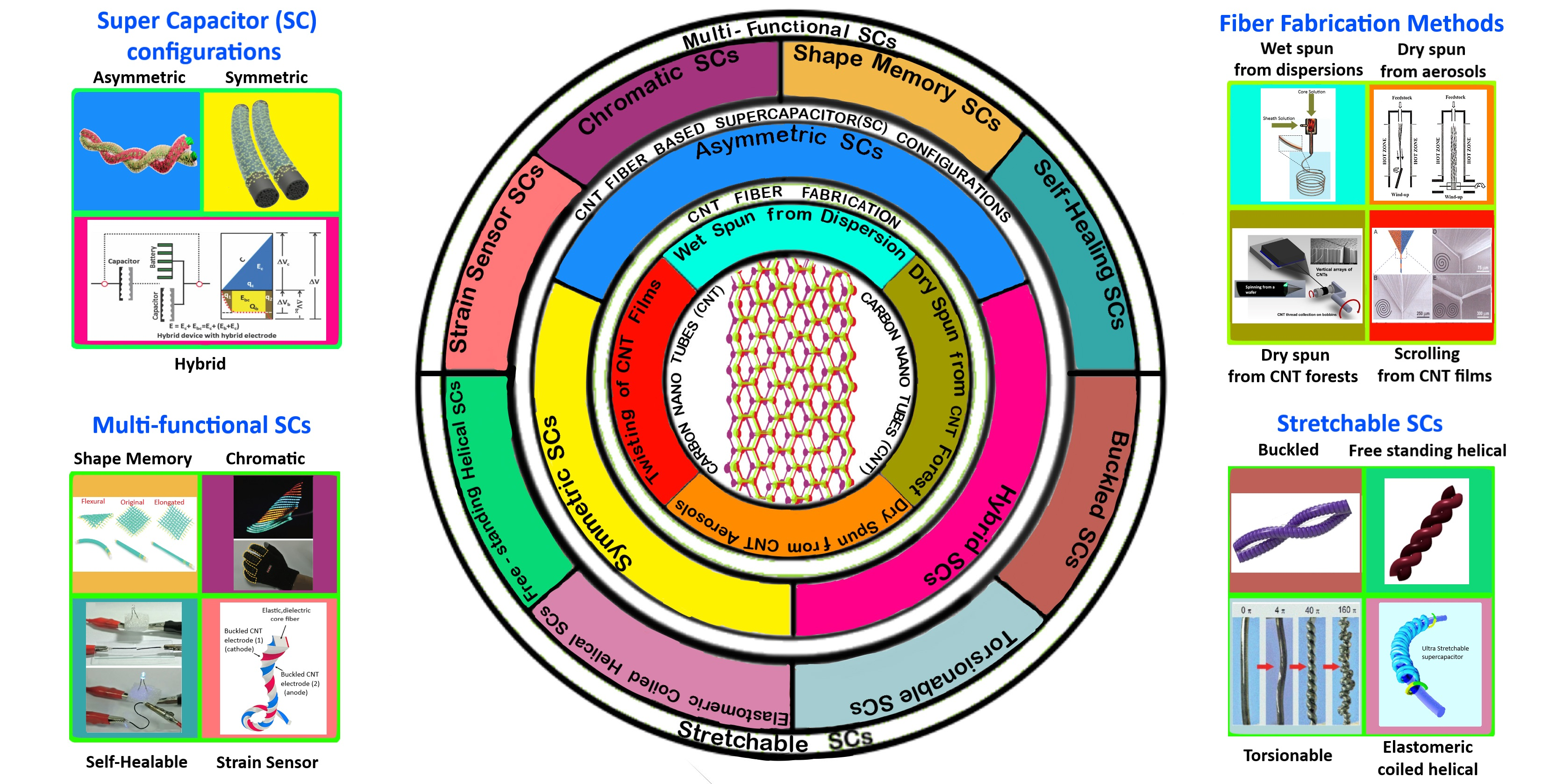
2. Background and Fundamentals of Supercapacitors
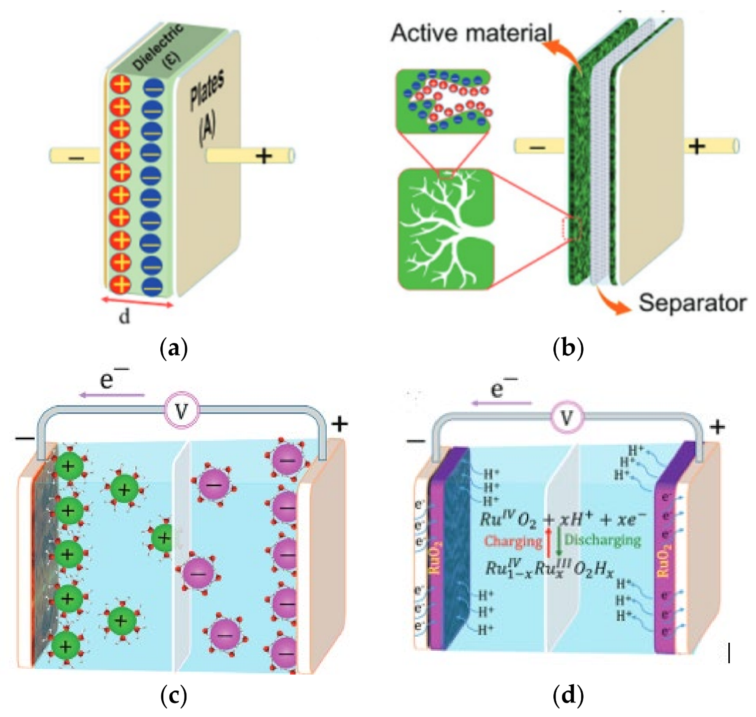
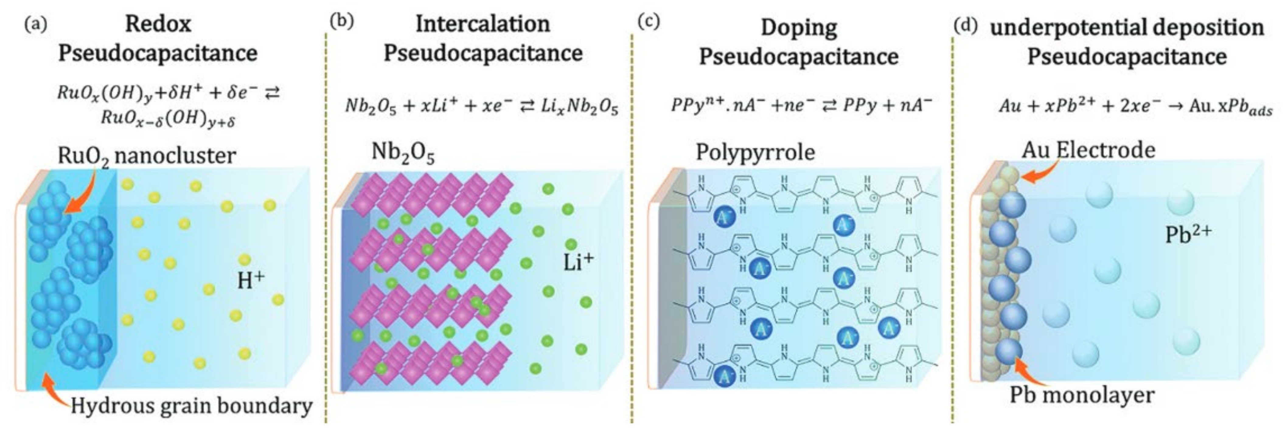
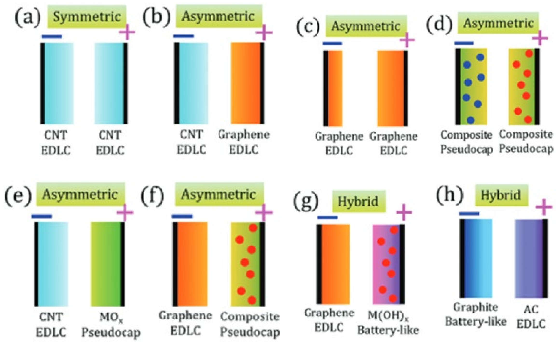
2.1. Type of SCs Based on Charge Storage
2.2. Supercapacitor Designs
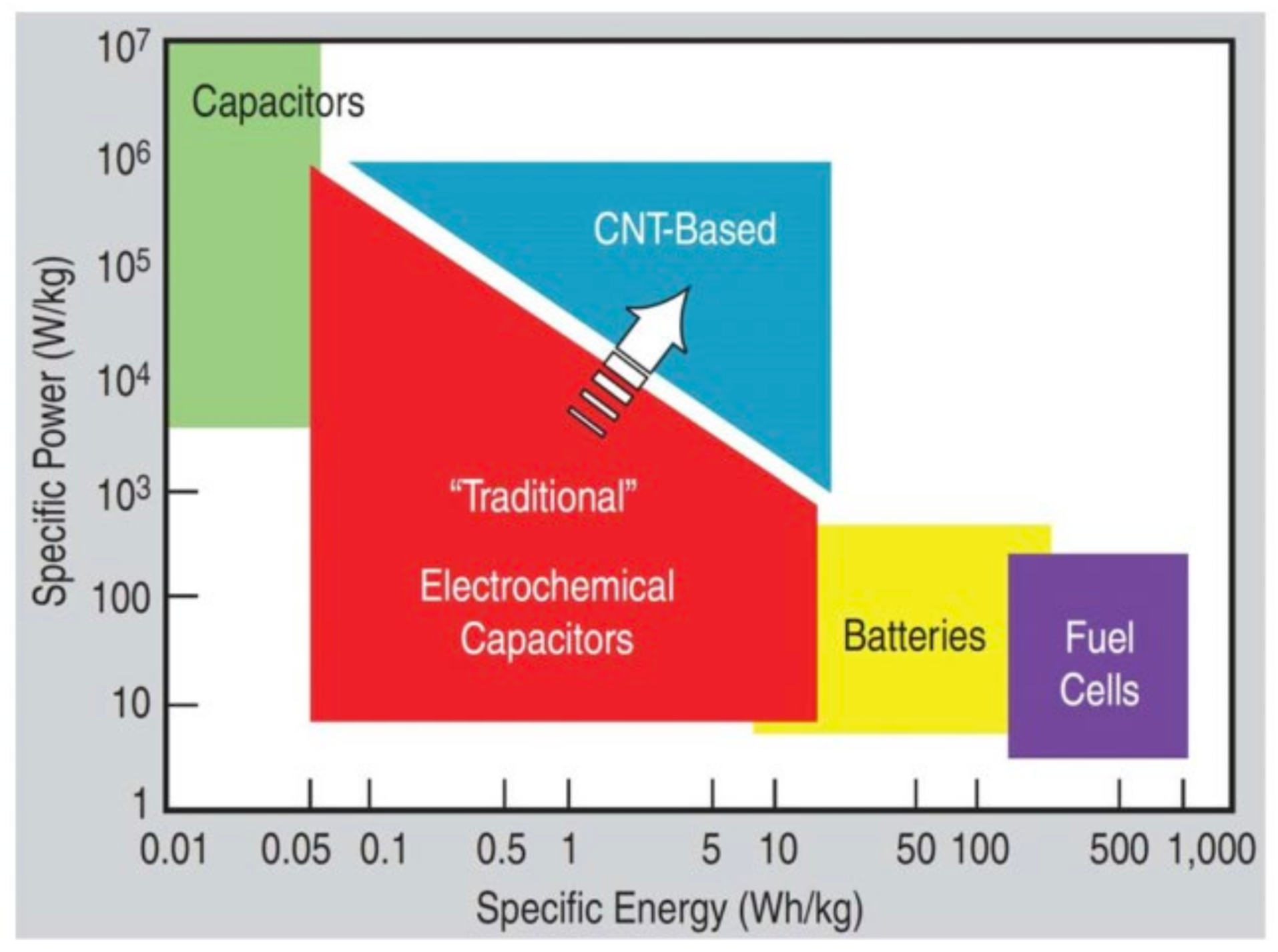
2.3. Performance Metrics of Supercapacitors
3. CNT Fiber for SCs
3.1. Fabrication of CNT Fibers
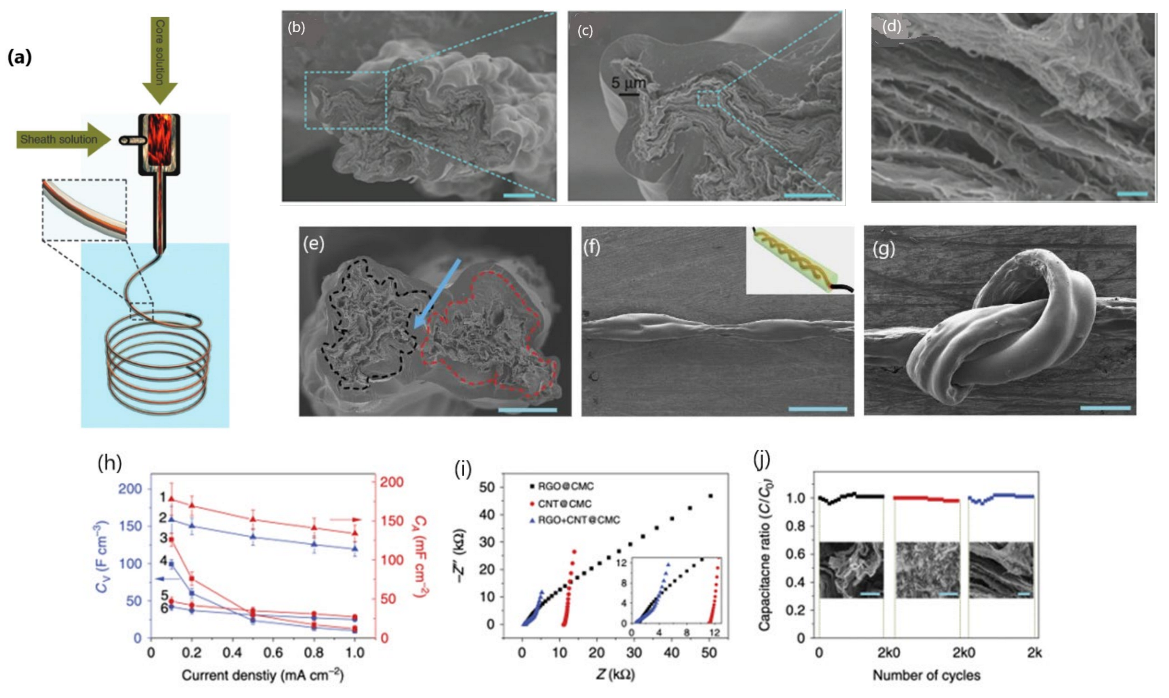
3.1.1. Wet Spinning from Dispersions
- The extrusion speed;
- The needle or spinneret diameter and shape;
- The quality and concentration of spinning dispersion;
- The rotation speed in the rotated spinning method;
- The nature of the coagulation bath (fast coagulation results in a non-homogenous structure, while slow coagulation imparts a homogenous structure);
- The drawing speed and ratio (a higher ratio improves the alignment, strength, and fiber conductivity);
- The post-treatment, if any (such as annealing, which is used to remove the oxides to make the fibers more conductive).
Wet Spinning and Incorporation of Pseudocapacitive Materials
- I.
- Metal oxides
- II.
- Conducting polymers
- III.
- Metal oxides and conducting polymers
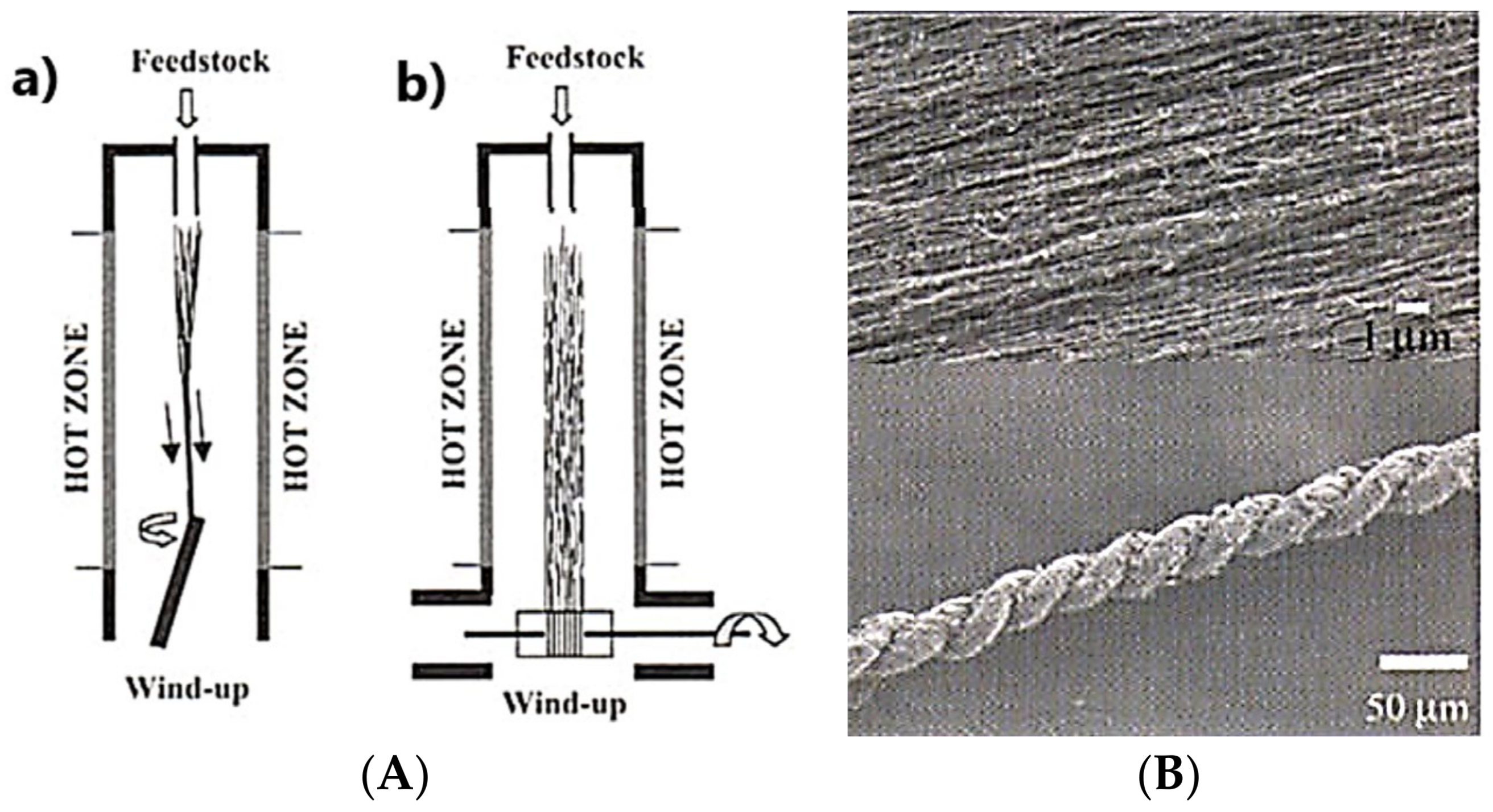
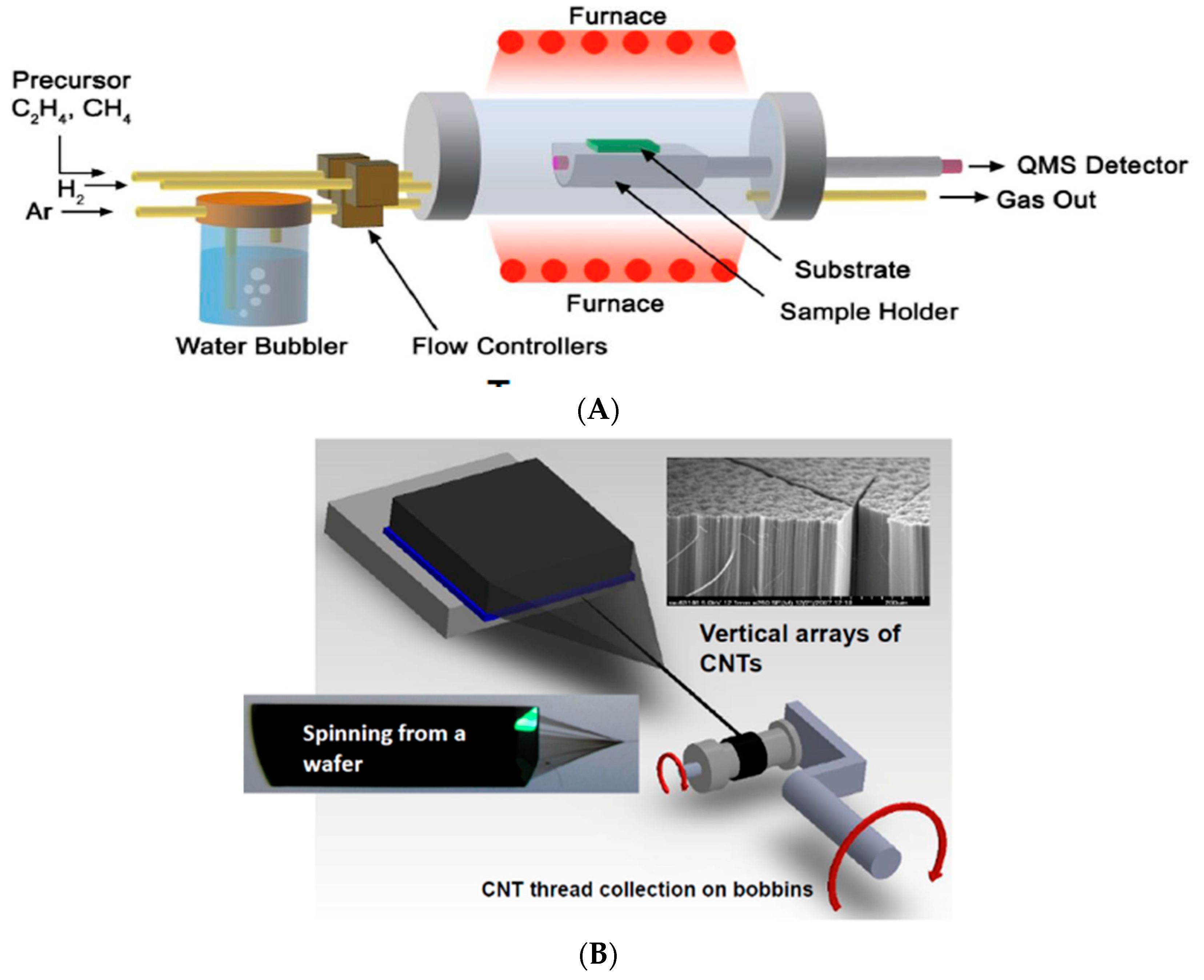
3.1.2. Dry Spinning from CNT Aerosols
- The carbon precursor;
- The catalyst concentration;
- The rate of hydrogen gas flow;
- The temperature of the pyrolysis.
- The CNT alignment, length, and structure;
- The post-treatment;
- The rate of the gas flow;
- The speed of the winding;
- The presence of particulate impurities and defects.
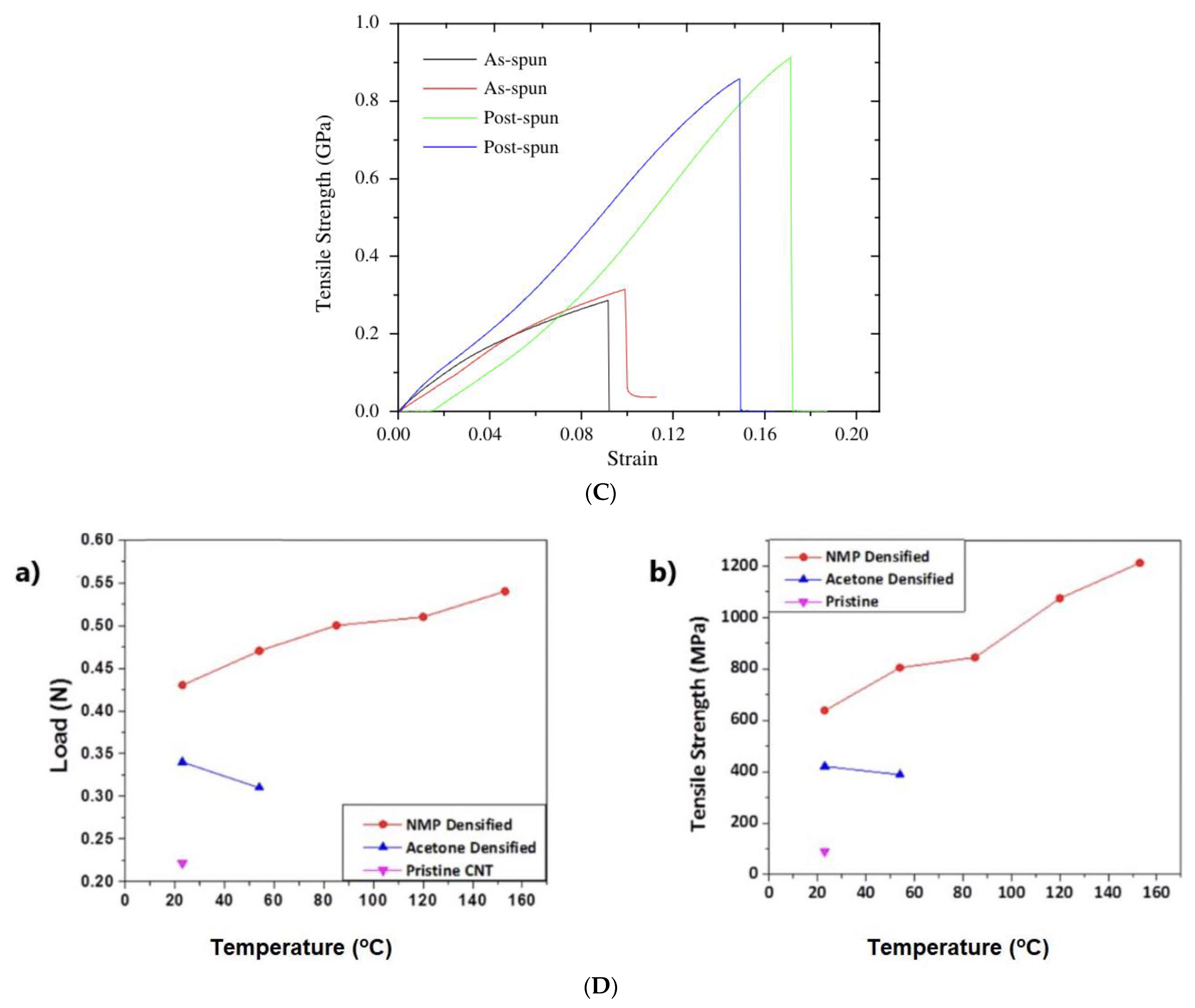
3.1.3. Dry Spinning from CNT Arrays
- Performing fiber post-treatments such as (a) solvent densification, which decreases the cross-sectional fiber area, bringing the CNT bundles closer; and (b) post-spinning from a spun fiber (Figure 7C,D)
- Introducing optimized twisting during the spinning process;
- Annealing at a high temperature to remove the oxides and amorphous carbon and to increase the conductivity;
- Cross-linking of the CNTs fibers with appropriate polymers to increase their strength.
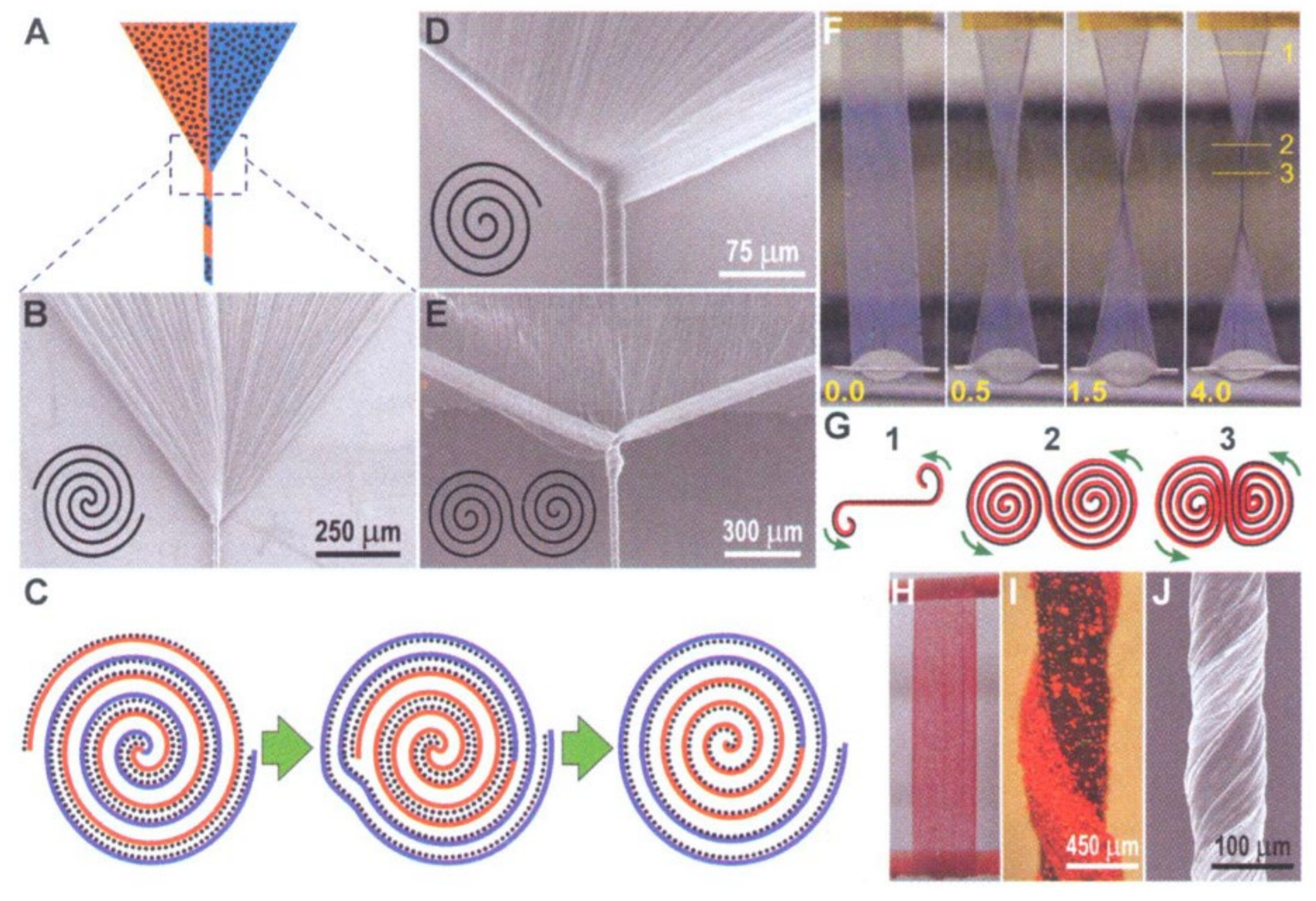
3.1.4. Twisting from CNT Films
4. Strategies to Improve the CNT Fiber’s Electrode Performance
4.1. Activation of CNT Fiber by Gamma Irradiation, Oxygen Plasma, or Acid Treatment
- The introduction of functional groups on the surface;
- The modification of the pore structure and the opening of new pores;
- Increasing the surface area;
- Decreasing the gravimetric density;
- Changing the surface energy by promoting hydrophilicity.
4.1.1. Activation by Gamma Radiation
4.1.2. Activation by Oxygen Plasma Treatment
4.1.3. Activation by Acid Treatment
4.2. Combining Pseudocapacitive Materials with CNT
4.2.1. Deposition of Active Materials after Fiber Fabrication
Metal Oxides and Hydroxides
Metal Sulfides
4.2.2. Incorporation of Active Material before or during Fiber Fabrication
- Higher loading is not possible since it does not increase the capacitance, as the accessible surface area is considerably reduced;
- The resistance increases along with the ion diffusion distance, substantially reducing the power density, resulting in greater energy consumption.
5. Strategies to Improve Device Performance
- Configuring an asymmetric type of capacitor;
- Using electrolytes with a wide working voltage;
- Modifying the electrode to widen the voltage window;
- Using redox electrolytes.
5.1. Metal Wire Co-Plying
5.2. Fabrication of an Asymmetric-Type Configuration
5.2.1. Transition Metal Oxide and Hydroxide Based Asymmetric Capacitors
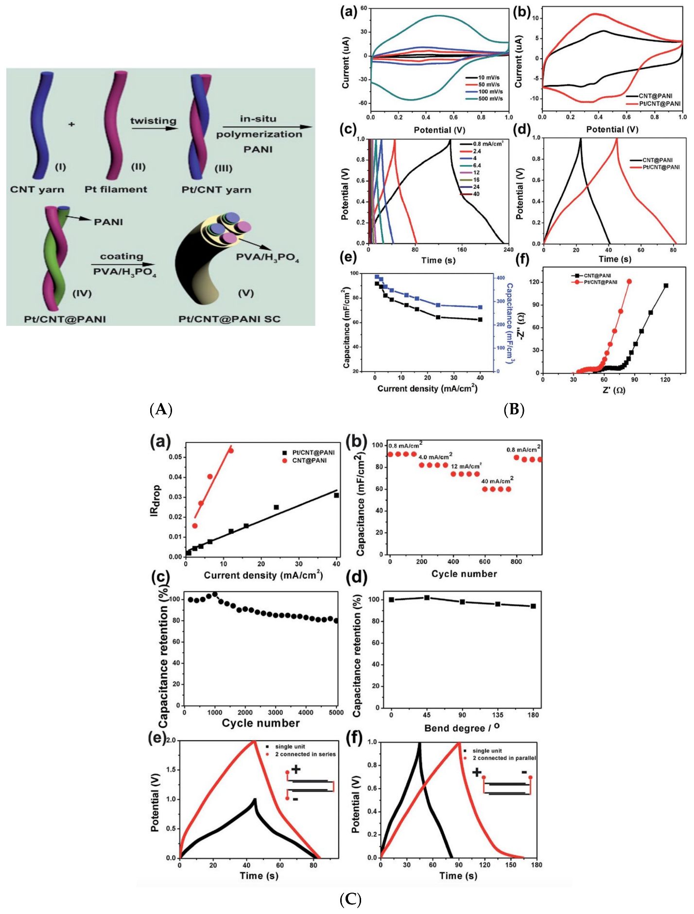
5.2.2. Conducting Polymer-Based Asymmetric Supercapacitors

| Electrodes | |||||||
|---|---|---|---|---|---|---|---|
| Positive | Negative | Electrolyte, Cell Voltage | Capacitance | Energy Density (Ed) | Power Density (Pd) | Capacity Retention/No. of Cycles | Ref |
| NCO/VG@ CNTF | VG@CNTF | PVA-KOH (1.8 V) | 188 F·g−1 @ 5 A·g−1 | 65 Wh·kg−1 | 100 W·kg−1 | 93.1% after 5k bending cycles | [69] |
| PANI-CNTF | FeC2O4/ FeOOH-CNTF | PVA-KOH (2.1 V) PVDF-EMIMBF4 (2.8 V) | - | 0.05–4.07 µWh·cm−2 0.17–3.06 µWh·cm−2 | 0.18–0.92 µW·cm−2 0.26–0.97 mW·cm−2 | 96.76% of Ed retention after 4k bending cycles | [70] |
| PEDOT: PSS | CNTF | Chitosan (1.4 V) | 21.4 F·g−1 | 5.83 Wh·kg−1 | 1399 W·kg−1 | 90% after 200 bending cycles | [71] |
| NiCo2S4@CNTF | VN@CNTF | PVA-LiCl (1.6 V) | 86.2 F·cm−3 @ 0.1 mA·cm−3 | 30.64 mWh·cm−3 | 80 mW·cm−3 | 91.94% after 5000 bending cycles | [72] |
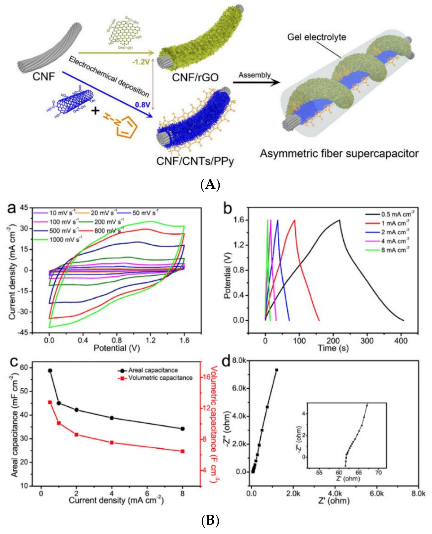
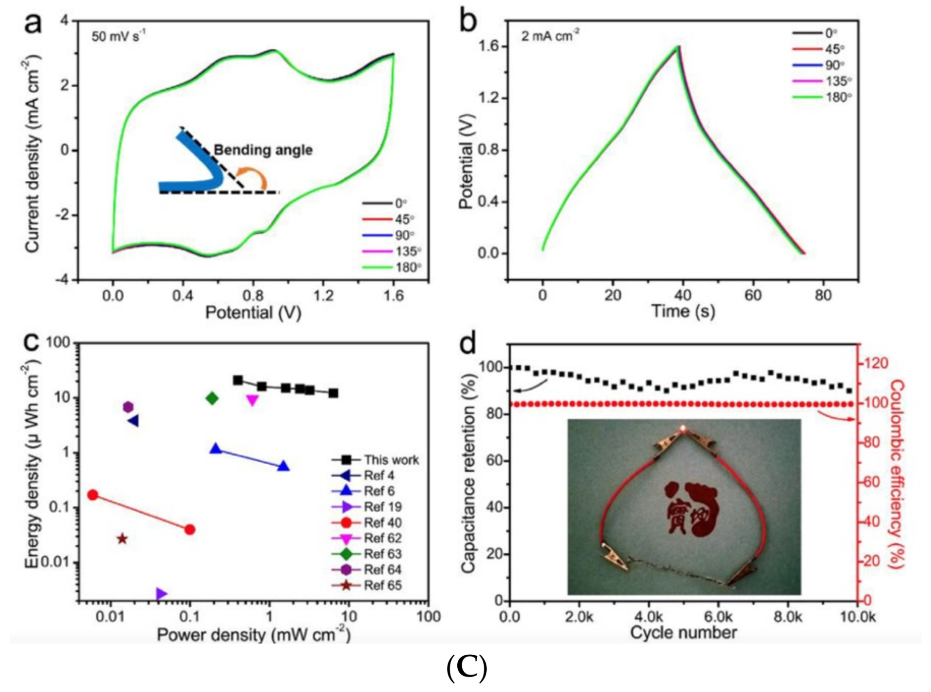
| CNTF/Porous CNT/PPY | CNTF/RGO | PVA-H3PO4 (1.6 V) | 58.82 mF. cm−2 (12.8 F·cm−3) | 20.91 µWh·cm−2 | 6.4 mW·cm−2 | 98.6% after 200 bend cycles, 90% after 10k cycles | [68] |
| GCF@NC@NCO | P-GCF | PVA-KOH (1.55 V) | 33.6 mF·cm−2@ 0.61 mA·cm−2 | 11.2 µWh·cm−2 | 472.1 µW·cm−2 | 93% after 10k cycles | [73] |
| N doped CNT on CNT/LTO | N doped CNT on CNT | LiPF6 (in 1:1 EC/DEC) (2.5 V) | - | 0.296 mWh·cm−2 | 0.172 mW·cm−2 | 100% after 4k cycles | [74] |
| CNT@PPY | CNT@CuCo2O4 | PVA-KOH (1.6 V) | 59.55 mF·cm−2 | 20 µWh·cm−2 | 5.115 mW·cm−2 | 80.1% after 8k cycles | [75] |
| VO2@PPY/CNT | VN@NC/CNT | PVA-LiCl (1.8 V) | 60.6 F·cm−3 | 27.3 mWh·cm−3 | 225 mW·cm−3 | 88.9% after 4k bending cycles | [76] |
| Ni(OH)2@ NiCo2O4/ CNTF | MoS2@Fe2O3/ CNTpaper | PVA-KOH (1.6 V) | 373 F·cm−2 @2 mA·cm−2 | 0.13 mWh·cm−2 | 3.2 mW·cm−2 | 80.3% after 2k cycles@ 20mAcm−2 | [63] |
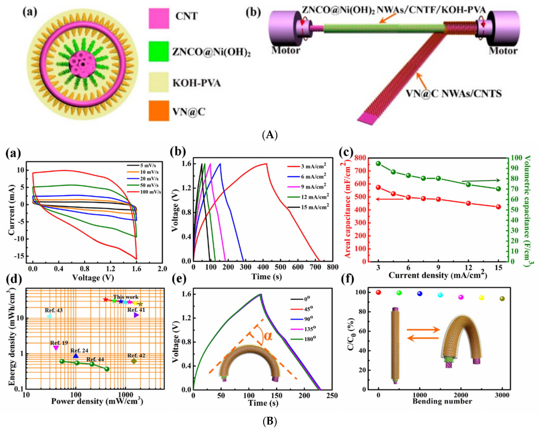
| ZNCO@Ni(OH)2 NWAs/CNTF | VN@C NWAs/CNTF | PVA-KOH (1.6 V) | 94.67 F·cm−3 @3 mA·cm−2 | 33.66 mWh·cm−3 | 396 mW·cm−3 | 93.6% after 3k bending cycles at 90° | [64] |
| Co3O4 NWAs/CNTF | VN (NWA)/CNTF | PVA-KOH (1.6 V) | 44.4 F·cm−3 @0.4 A·cm−3 | 15.79 mWh·cm−3 | 3.232 W·cm−3 | 93.12% after 4k cycles 93.01% after 3k bending cycles | [62] |
| MNCO/CNTF | VN@C(NWA)/ CNTF | PVA-KOH (1.6 V) | 62.3 F·cm−3 @1 mA·cm−2 | 22.2 mWh·cm−3 | 213.3 mW·cm−3 | 90.2%after 3.5k bending cycles | [65] |
| ZNCO NWA/CNTF | VN/CNTF | PVA-KOH (1.6 V) | 50.0 F·cm−3 @0.1 A·cm−3 | 17.78 mWh·cm−3 | 80.0 mW·cm−3 | 91.0% after 3K bending cycles at 90° | [77] |
| Ti@TiO2 | CNTF | PVA-H3PO4 (1.4 V) | - | 11.7 Wh·kg−1 | 2060.0 W·kg−1 | 91.0% after 1.2k bending cycles | [78] |
| CNT/MnO2 | CF/PPY | LiCl-PVA (1.6 V) | 66.27 mF·cm−2 | 23.56 µWh·cm−2 | - | 83% after 5k cycles | [79] |
| MnO2/CNT | PI/CNT | CMC/Na2SO4 (2.1 V) | 59.2 mF·cm−2 @0.74 mA·cm−2 | 36.4 µWh·cm−2 30.2 µWh·cm−2 | 0.78 mW·cm−2 15.6 mW·cm−2 | 96.3% after 2k cycles | [66] |
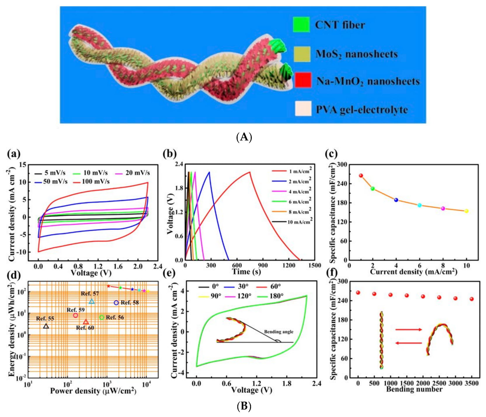
| Na-MnO2@CNTF | MoS2@CNTF | PVA/Na2SO4 (2.2 V) | 265.4 mF·cm−2 @1 mA·cm−2 | 178.4 µWh·cm−2 | 1100.9 µW·cm−2 | 90% after 5k cycles | [67] |
5.3. Use of Electrolytes with a Wide Potential Window
- High ionic conductivity;
- Environmental benignity;
- Non-flammability;
- Small ionic radius.
6. Stretchability of Wearable Supercapacitors
6.1. Physical Configurations
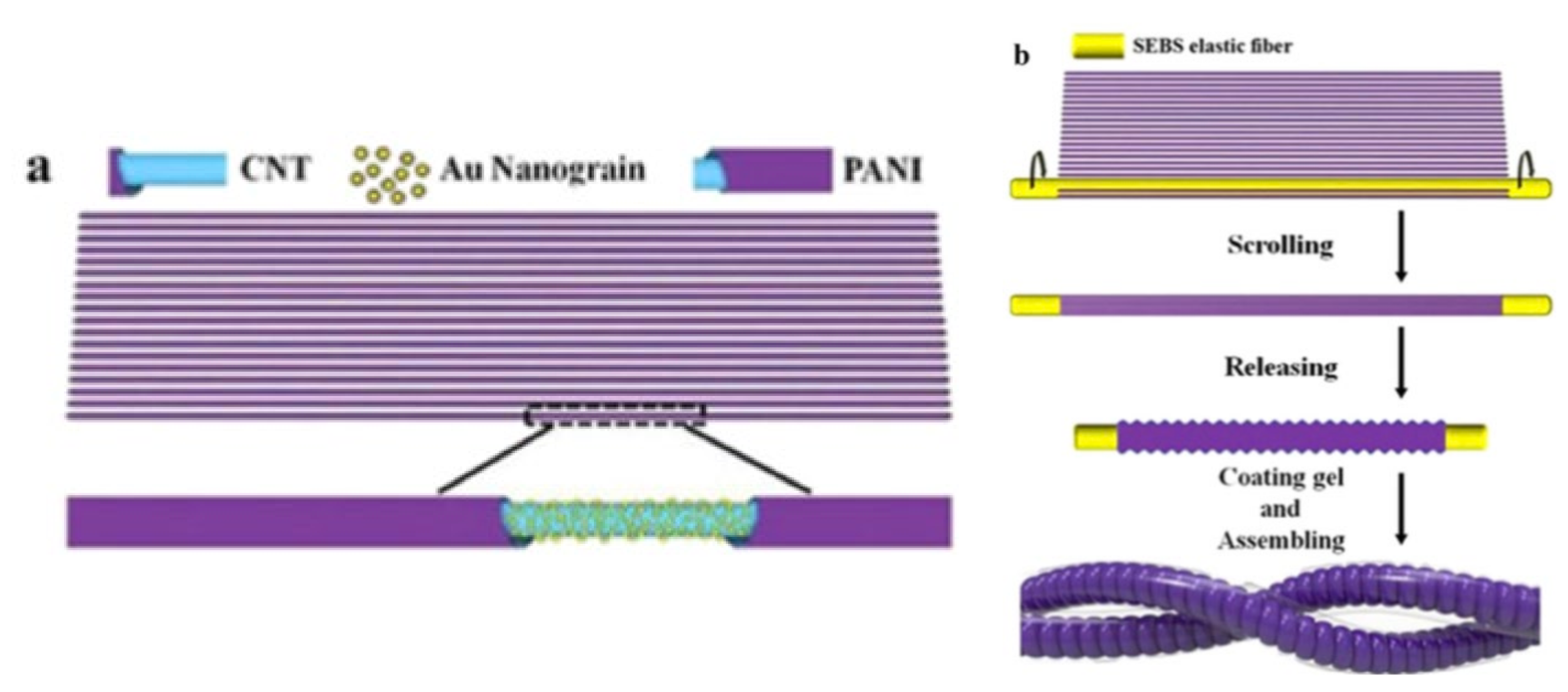
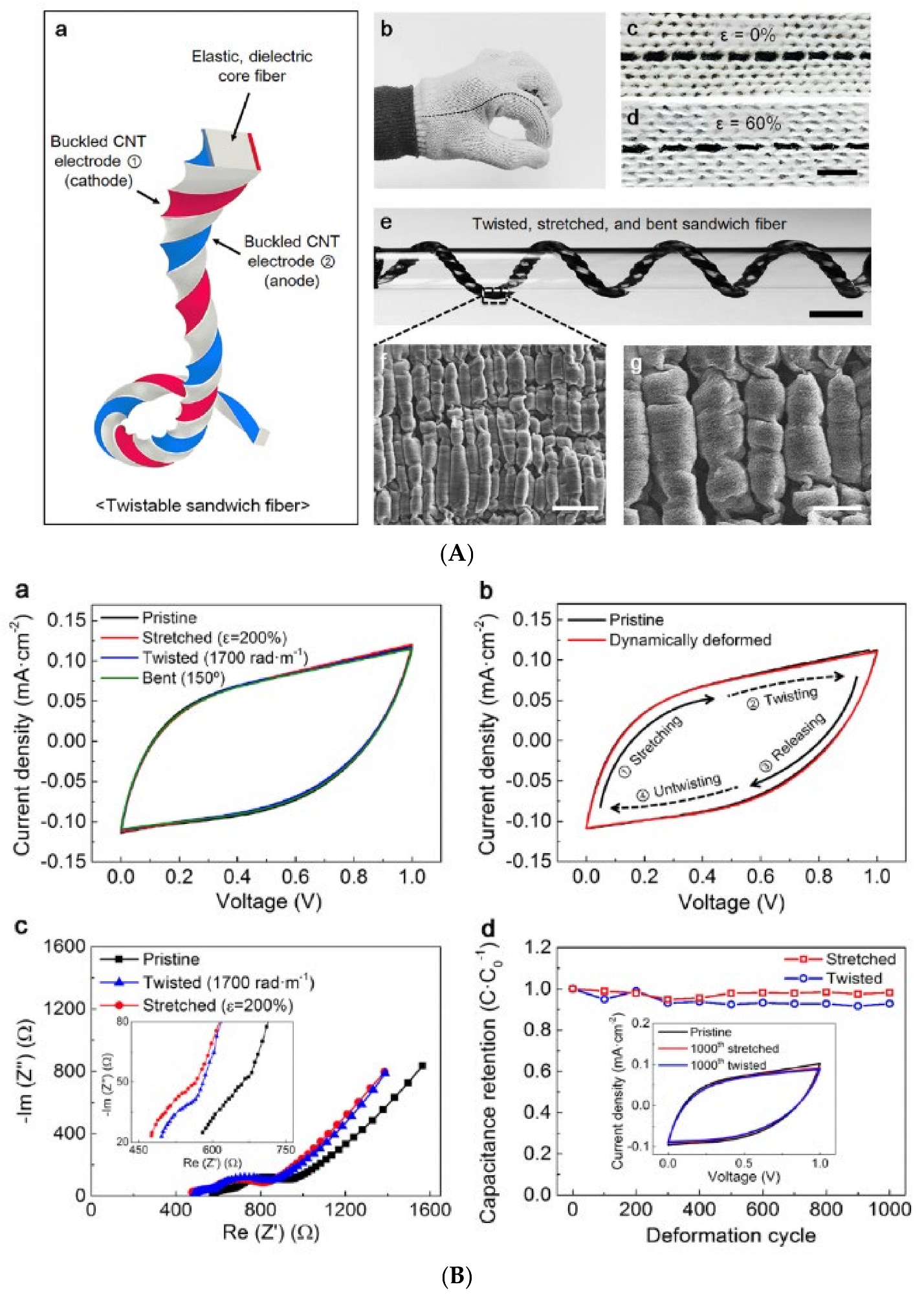
6.1.1. Buckled CNT Sheets with an Elastomer Core
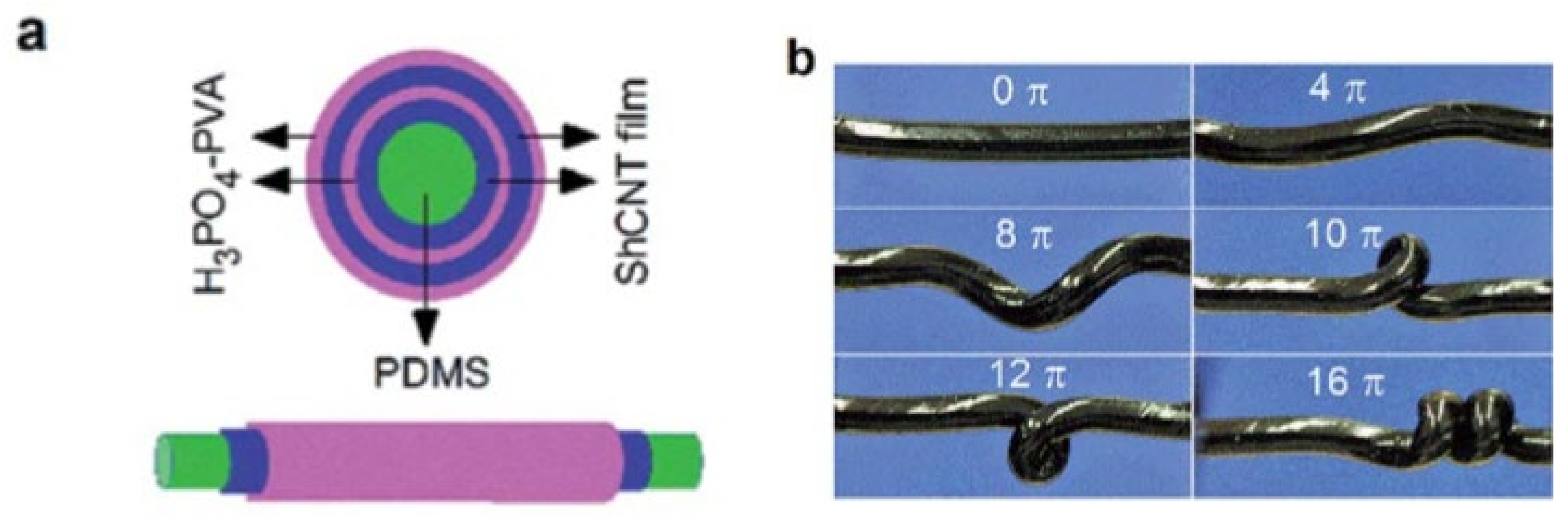
6.1.2. Coaxial CNT Layers with an Elastomer Core
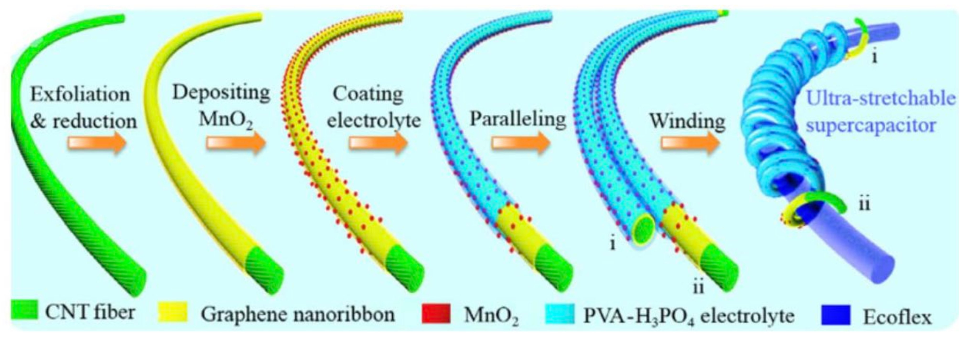
6.1.3. Helical CNT Fibers with an Elastomer Core
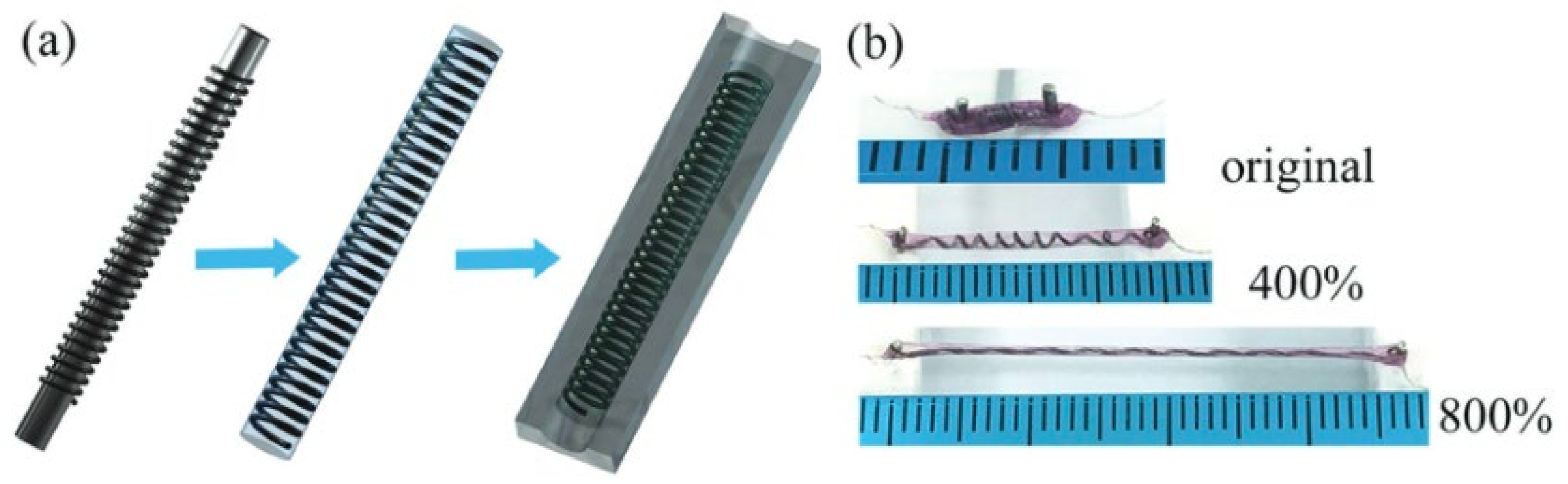
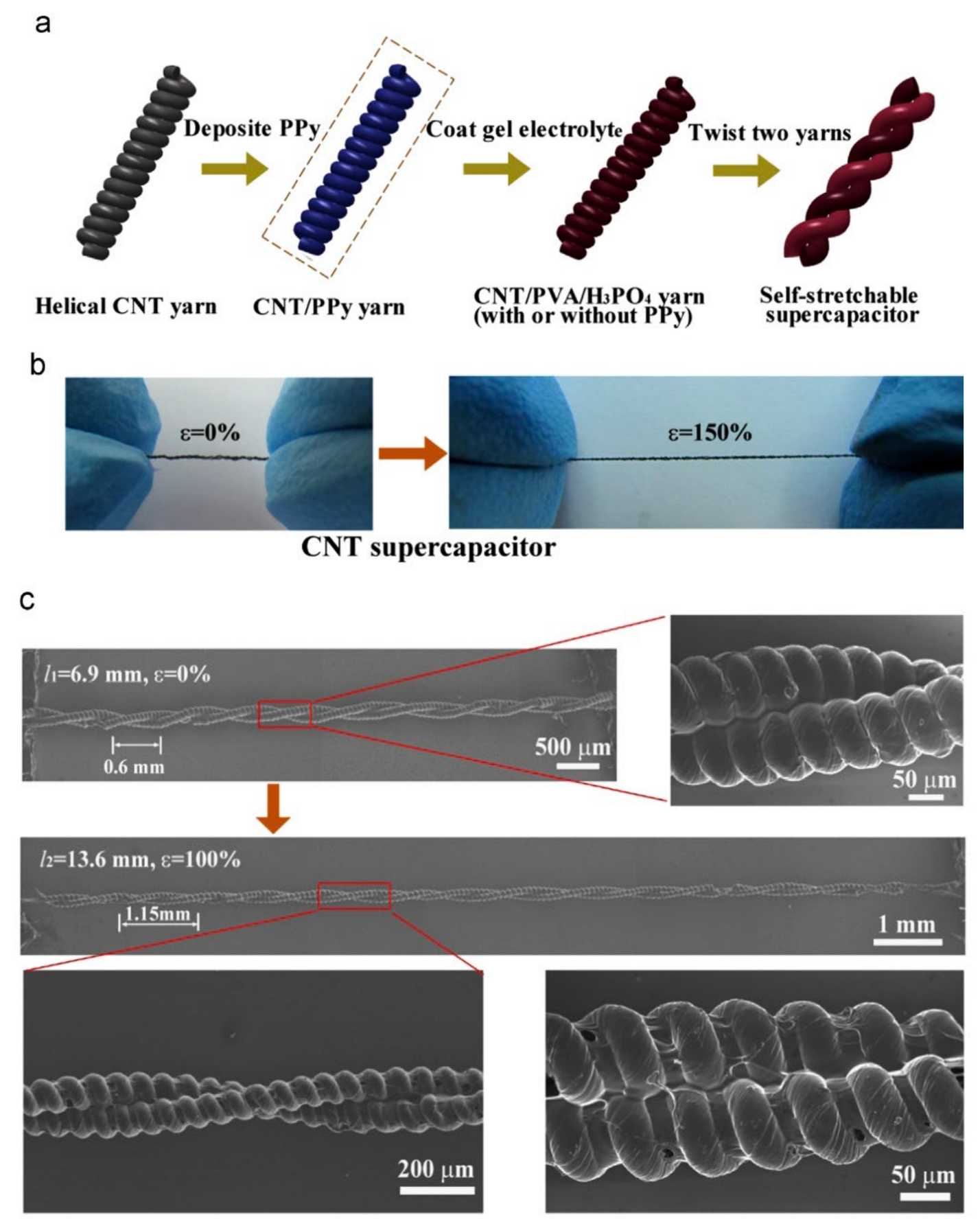
6.1.4. Freestanding Helical CNT Fibers
6.1.5. Other Configurations
| Configuration | Pseudocapacitive Material/Electrolyte | Strain, Capacitance Retention | Bend, Capacitance Retention | Ultimate Strength | Capacitance | Ref |
|---|---|---|---|---|---|---|
| Symmetrical coiled CNT sheets, Nylon core | MnO2/ PVA-LiCl | 150%, 88% | - | - 68 MPa | 5.4 mF·cm−1 40.9 mF·cm−2 | [96] |
| Wire-Drawn-Die _ Free Standing Symmetrical Helical CNT-PPy composite fiber | PPY/ PVA-H3PO4 | - | 180°, 100%/ 100% after 1k cycles @90° | - | 69 F·g−1 | [91] |
| Free Standing Symmetrical Helical CNT yarn | PPY/PVA-H3PO4 | 150%, 94% | - | - | 19 F·g−1 | [92] |
| Asymmetrical Buckled CNT sheets Eco Flex 0040 Elastomer Core | MnO2/PEDOT/ PVA-LiCl | 200%, 97.7% | 150%, 96.8% | - | 2.38 mF·cm−1 11.88 mF·cm−2 | [82] |
| Symmetrical Buckled CNT Sheets, SEBS Elastomer Core | Au and PANI/ PVA-H3PO4 | 400%/ 100% after 1k cycles | - | - | 8.7 F·g−1 @1A·g−1 | [81] |
| Asymmetrical Helical Oxidized CNT Fiber, Elastomer Core | MnO2@PEDOT:PSS@ OCNTF (positive) MoS2@CNTF(negative) PVA-LiCl | 100%, 92% after 3k cycles | - | - | 278.6 mF·cm−2 | [87] |
| Symmetrical Coaxial Layered CNT Sheets, Eco flex Elastomer Core | - PVA-H3PO4 | 650%, 88% | - | - | 2.42–2.68 mF·cm−1 | [85] |
| Twisted symmetrical Buckled CNT Sheets, SEBS Elastomer Core | MnO2 & RuO2 PVA-H3PO4 | 200%, 100% | - | - | 25.0 F·g−1 | [83] |
| Symmetrical CNT Dipped Yarns/Ag plated Double-covered yarn polymer | (PVDF-HFP)/ EMIMBF4 | 150%, 75% 5k cycles | 120°, 80%, 5k cycles | 46.6 MPa | 4.8 F·cm−3 @200 mA·cm−3 | [88] |
| Symmetrical Buckled CNT Sheets Elastomer Core | PANI PVA-H2SO4 | 100%, 98%, 100 cycles | - | - | 394 F·g−1 | [84] |
| Helically Coiled CNT/ Graphene Fibers, Coated in SEBS | PANI PVA-H3PO4 | 800%, 99.2% 800%, 77.3%, 5k cycles | - | - | 138 F·g−1 | [90] |
| Helically Coiled Symmetrical CNT/Graphene Fibers, Eco flex Elastomer Core | MnO2 PVA-H3PO4 | 850%, 82% after 1k cycles @ 700% strain | 90°, 100%, 1k cycles | - | 14.02 mF·cm−2 | [86] |
| Helically Coiled Symmetrical CNT Fibers, Spandex Elastomer Core | MnO2 PVA-KOH | 80%, 92.1%, 500 cycles | 180°, 95.3%, 500 cycles | - | 685 mF·cm−2 | [89] |
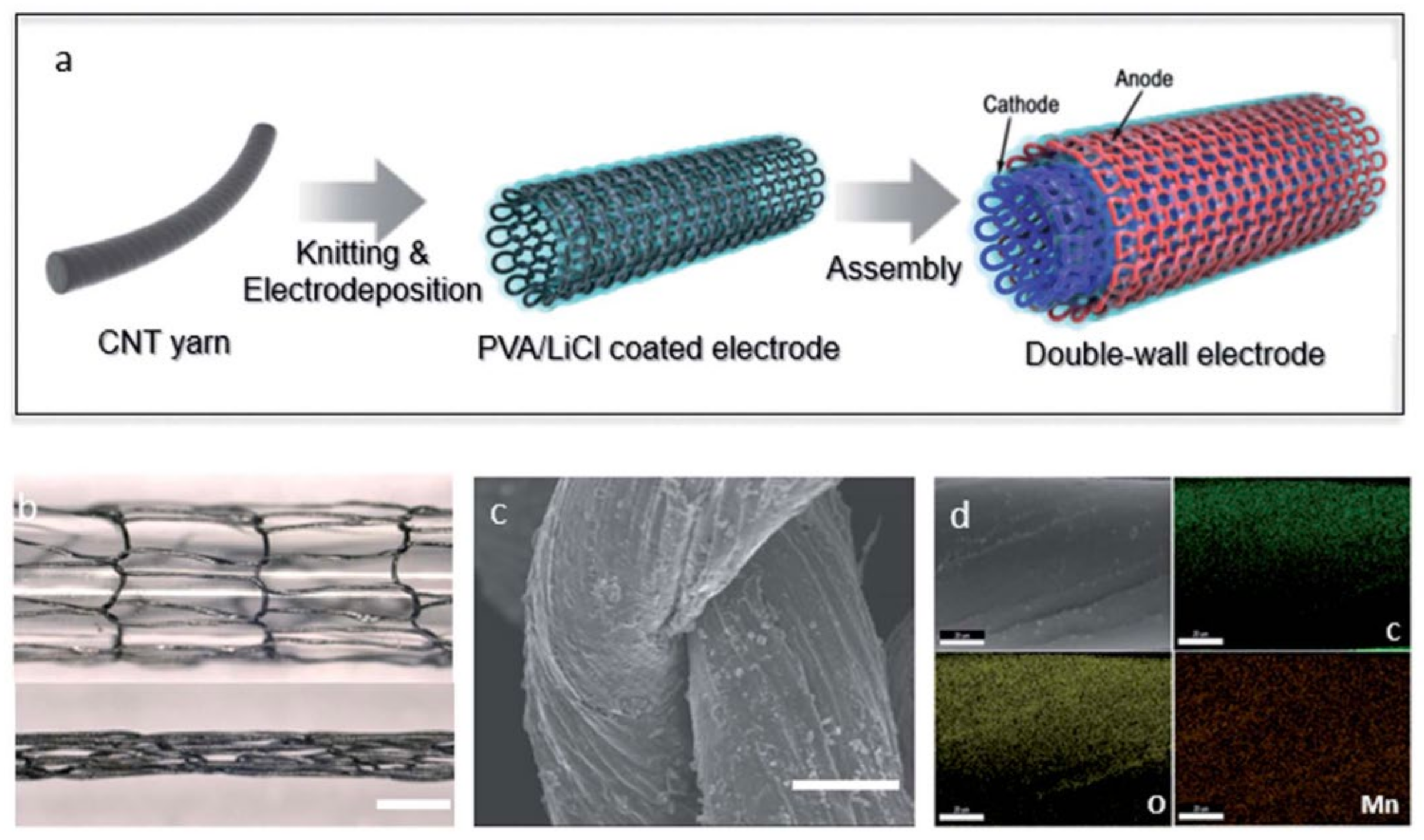
| Coaxial Knitted CNT Fibers | MnO2 PVA-LiCl | 100%, 98%, 500 cycles | 160°, 100% | - | 321.08 mF·cm−1 511.28 mF·cm−2 | [95] |
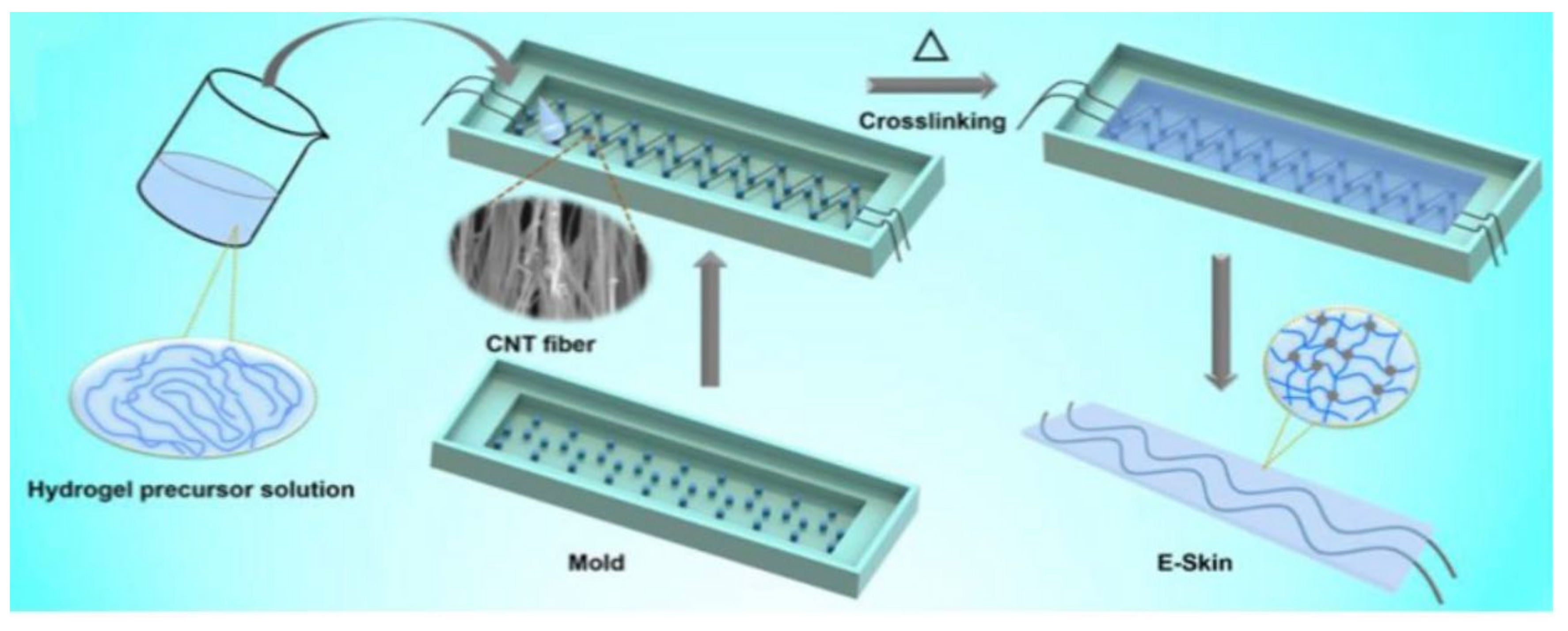
| Parallel/Symmetrical Sinusoidal CNT Fibers, PAAm Hydrogel | - PAAm-LiCl | 50%, 90.4%, 3k cycles | - | 130 MPa | 10.6 mF·cm−2 | [80] |
| Helically Coiled Symmetrical CNT Fibers, Silicone Elastomer Core | PVA-HCl | 70%, 97%, 1k cycles | 180°, 97%, 1k cycles | - | 170 mF·cm−2 @100 mV·s−1 | [97] |
| Helically Coiled Symmetrical PEDOT@BacterialCellulose (BC)/CNT Fiber | PEDOT, BC PVA-H3PO4 | 1000%, 94.4%, 1k cycles | - | - | 175.1 F·g−1 | [93] |
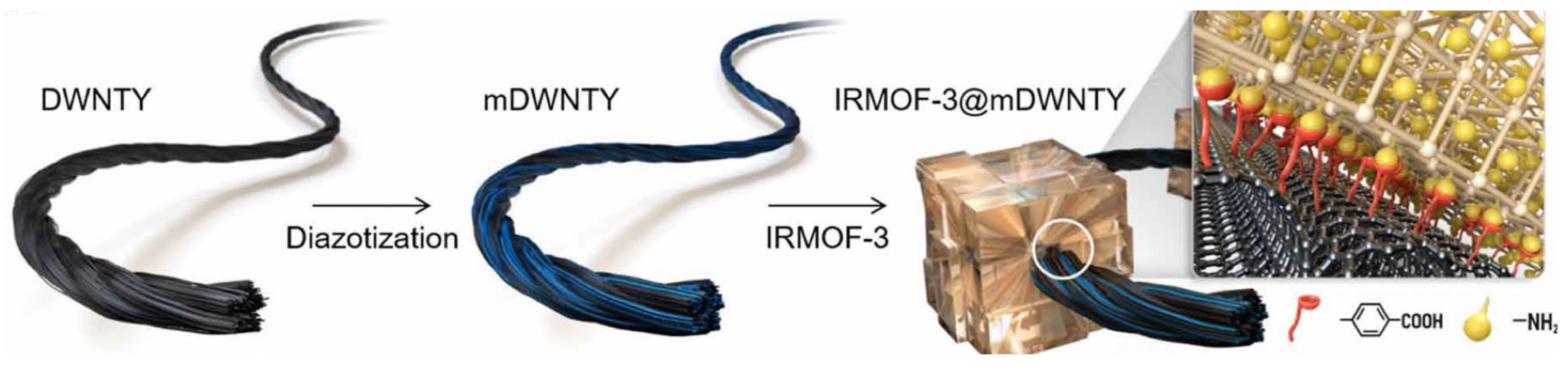
| Helically Coiled Symmetrical CNT Fibers in Metal-Organic Framework | MOF, PVA-DMSO | - | 88%, 500 cycles | 492.8 MPa | 225.2 F·cm−3 | [94] |
7. Multifunctional CNT Supercapacitors
7.1. Strain Sensors
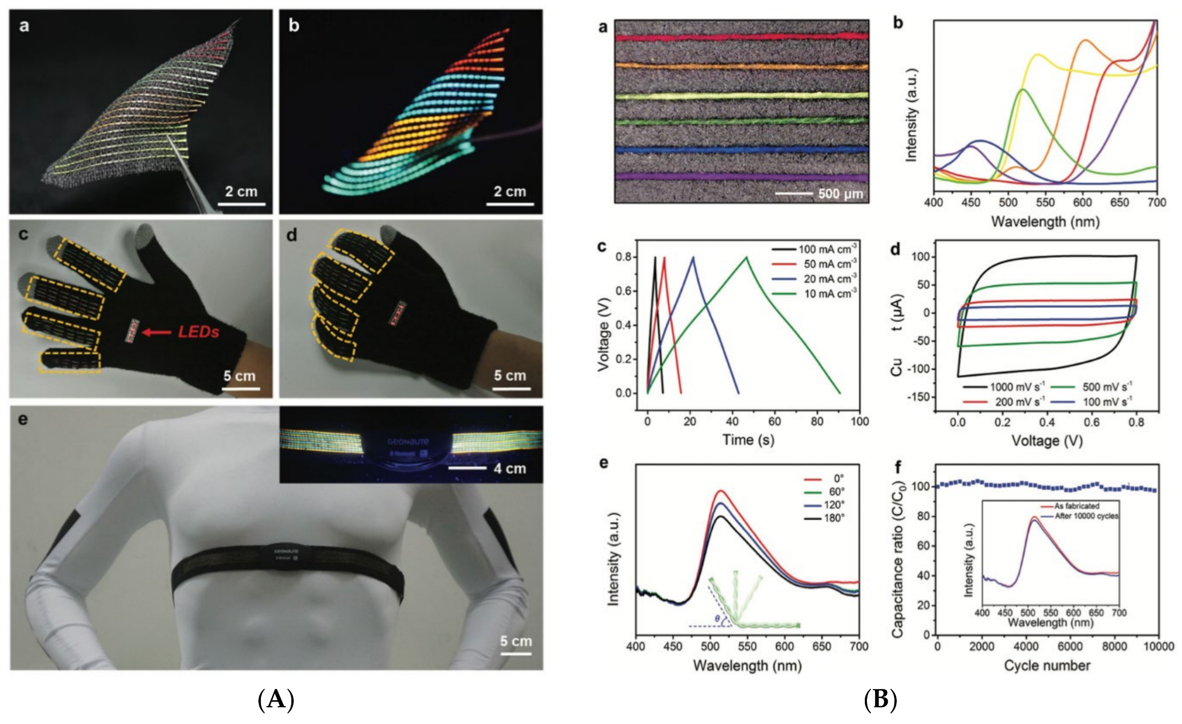
7.2. Chromatic Supercapacitors
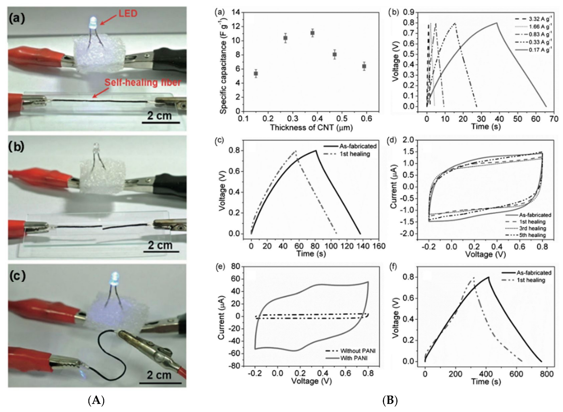
7.3. Self-Healing CNT Supercapacitors
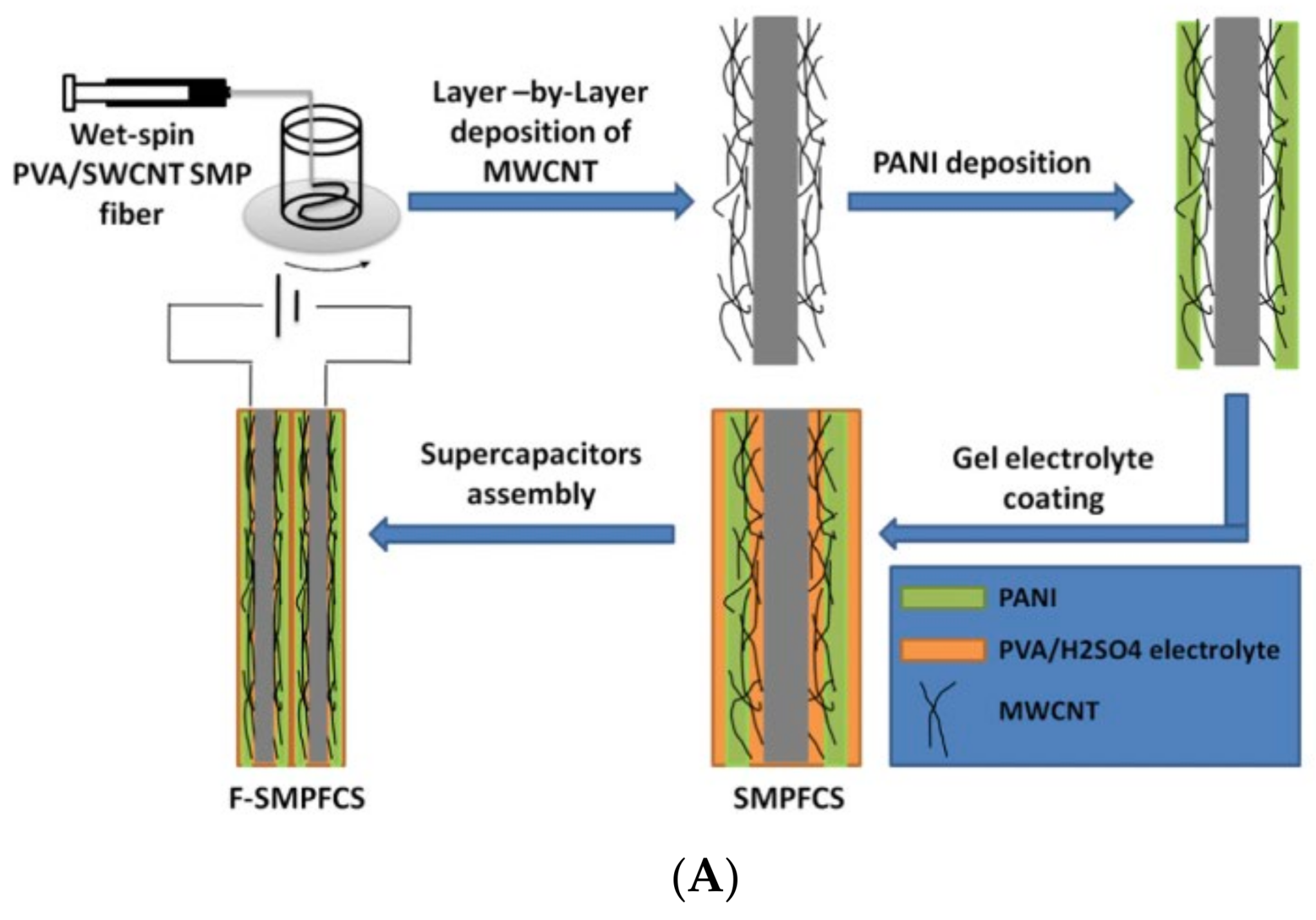
7.4. Shape-Retaining CNT Supercapacitors
8. Current Challenges Related to CNT-Based Fiber Supercapacitors
- The energy densities of the CNT SCs are low compared to other energy storage devices such as microbatteries. The CNT fiber electrodes used as scaffolds and active materials, even with a high specific surface area, result in moderate energy density. This could be due to the non-accessibility of the electrolytes to the electrode. Modifying the surface area to make it electrolyte-accessible and matching the electrode’s pore diameter with the electrolyte ions’ size could result in higher performance. The optimization of the fiber design and configurations to ensure the complete utilization of the electrode needs to be considered;
- Most of the current wearable SC research is conducted using PVA-KOH electrolytes, as they are mechanically robust with good electrochemical stability and low costs. However, this causes the limitation of a narrow PW, resulting in a relatively low energy density. As an alternative, electrolytes with wider PWs with an organic or ionic nature can be used. Additionally, the development of new electrolytes that are safer and ionically conductive with wide PWs need to be pursued;
- Electrolytes based on sulfuric acid, phosphoric acid, and KOH are corrosive. Most research studies do not use encapsulation, making their use unsafe. Wearable SCs employing corrosive electrolytes must be encapsulated with a polymer that does not affect the device’s electrochemical performance;
- The unit cost of CNT yarn is still high, which hinders the scalability and mass production of CNT-yarn-based devices. Nevertheless, inexpensive CNT fibers are expected to appear on the market in the near future;
- As wearable electronics represent a rapidly advancing field, there is a huge market for products such as smart textiles, which necessitate scalability combined with low-cost production. Moreover, the mechanical strength aspects of the CNT fibers (flexibility, stretchability, stiffness, and good endurance life after dynamic mechanical stress cycles) must match the textile standards for the satisfactory integration with the fabric via knitting, sewing, or weaving. Therefore, more collaborations between textile or garment experts and CNT fiber researchers are necessary, which will bring to life technologies that will align the CNT fibers’ physical and mechanical properties with the conventional fabric materials, thereby resulting in viable wearable electronics.
9. Conclusions
Funding
Institutional Review Board Statement
Informed Consent Statement
Data Availability Statement
Conflicts of Interest
References
- Meng, F.; Li, Q.; Zheng, L. Flexible fiber-shaped supercapacitors: Design, fabrication, and multi-functionalities. Energy Storage Mater. 2017, 8, 85–109. [Google Scholar] [CrossRef]
- Huang, Q.; Wang, D.; Zheng, Z. Textile-Based Electrochemical Energy Storage Devices. Adv. Energy Mater. 2016, 6, 1600783. [Google Scholar] [CrossRef]
- Chen, S.; Qiu, L.; Cheng, H.-M. Carbon-Based Fibers for Advanced Electrochemical Energy Storage Devices. Chem. Rev. 2020, 120, 2811–2878. [Google Scholar] [CrossRef] [PubMed]
- Sun, J.; Huang, Y.; Sea, Y.N.S.; Xue, Q.; Wang, Z.; Zhu, M.; Li, H.; Tao, X.; Zhi, C.; Hu, H. Recent progress of fiber-shaped asymmetric supercapacitors. Mater. Today Energy 2017, 5, 1–14. [Google Scholar] [CrossRef]
- Lu, Z.; Raad, R.; Safaei, F.; Xi, J.; Liu, Z.; Foroughi, J. Carbon Nanotube Based Fiber Supercapacitor as Wearable Energy Storage. Front. Mater. 2019, 6, 138. [Google Scholar] [CrossRef]
- Conway, B.E. Electrochemical Supercapacitors: Scientific Fundamentals and Technical Applications; Kluwer Academic/Plenum: New York, NY, USA, 1999. [Google Scholar]
- Senthilkumar, S.T.; Wang, Y.; Huang, H. Advances and prospects of fiber supercapacitors. J. Mater. Chem. A 2015, 3, 20863–20879. [Google Scholar] [CrossRef]
- Xie, P.; Yuan, W.; Liu, X.; Peng, Y.; Yin, Y.; Li, Y.; Wu, Z. Advanced carbon nanomaterials for state-of-the-art flexible supercapacitors. Energy Storage Mater. 2020, 36, 56–76. [Google Scholar] [CrossRef]
- Pan, Z.; Yang, J.; Zhang, Y.; Gao, X.; Wang, J. Quasi-solid-state fiber-shaped aqueous energy storage devices: Recent advances and prospects. J. Mater. Chem. A 2020, 8, 6406–6433. [Google Scholar] [CrossRef]
- Cherusseri, J.; Kumar, K.S.; Choudhary, N.; Nagaiah, N.; Jung, Y.; Roy, T.; Thomas, J. Novel mesoporous electrode materials for symmetric, asymmetric and hybrid supercapacitors. Nanotechnology 2019, 30, 202001. [Google Scholar] [CrossRef] [PubMed]
- Joseph, N.; Shafi, P.M.; Bose, A.C. Recent Advances in 2D-MoS2 and its Composite Nanostructures for Supercapacitor Electrode Application. Energy Fuels 2020, 34, 6558–6597. [Google Scholar] [CrossRef]
- Forouzandeh, P.; Kumaravel, V.; Pillai, S.C. Electrode Materials for Supercapacitors: A Review of Recent Advances. Catalysts 2020, 10, 969. [Google Scholar] [CrossRef]
- Wang, J.; Li, F.; Zhu, F.; Schmidt, O.G. Recent Progress in Micro-Supercapacitor Design, Integration, and Functionalization. Small Methods 2018, 3, 1800367. [Google Scholar] [CrossRef]
- Dong, L.; Xu, C.; Li, Y.; Huang, Z.-H.; Kang, F.; Yang, Q.-H.; Zhao, X. Flexible electrodes and supercapacitors for wearable energy storage: A review by category. J. Mater. Chem. A 2016, 4, 4659–4685. [Google Scholar] [CrossRef]
- Yang, P.; Mai, W. Flexible solid-state electrochemical supercapacitors. Nano Energy 2014, 8, 274–290. [Google Scholar] [CrossRef]
- Yang, Z.; Ren, J.; Zhang, Z.; Chen, X.; Guan, G.; Qiu, L.; Zhang, Y.; Peng, H. Recent Advancement of Nanostructured Carbon for Energy Applications. Chem. Rev. 2015, 115, 5159–5223. [Google Scholar] [CrossRef] [PubMed]
- Beguin, F.; Frackowiak, E.; Gogotsi, Y. Carbons for Electrochemical Energy Storage and Conversion Systems; CRC Press: Boca Raton, FL, USA, 2009. [Google Scholar] [CrossRef]
- Frackowiak, E.; Abbas, Q.; Béguin, F. Carbon/carbon supercapacitors. J. Energy Chem. 2013, 22, 226–240. [Google Scholar] [CrossRef]
- Chen, D.; Jiang, K.; Huang, T.; Shen, G. Recent Advances in Fiber Supercapacitors: Materials, Device Configurations, and Applications. Adv. Mater. 2019, 32, e1901806. [Google Scholar] [CrossRef] [PubMed]
- Zhang, X.; Chen, X.; Bai, T.; You, X.-Y.; Zhao, X.; Liu, X.-Y.; Ye, M.-D. Recent advances in flexible fiber-shaped supercapacitors. Acta Phys. Sin. 2020, 69, 178201. [Google Scholar] [CrossRef]
- Jang, Y.; Kim, S.M.; Spinks, G.M.; Kim, S.J. Carbon Nanotube Yarn for Fiber-Shaped Electrical Sensors, Actuators, and Energy Storage for Smart Systems. Adv. Mater. 2019, 32, 1902670. [Google Scholar] [CrossRef] [PubMed]
- Yao, Y.; Li, N.; Lv, T.; Chen, T. Carbon Nanotube Fibers for Wearable Devices. In Industrial Applications of Carbon Nanotubes; Elsevier: Amsterdam, The Netherlands, 2016; pp. 347–379. [Google Scholar] [CrossRef]
- Wang, Y.; Song, Y.; Xia, Y. Electrochemical capacitors: Mechanism, materials, systems, characterization and applications. Chem. Soc. Rev. 2016, 45, 5925–5950. [Google Scholar] [CrossRef] [PubMed]
- Noori, A.; El-Kady, M.F.; Rahmanifar, M.S.; Kaner, R.B.; Mousavi, M.F. Towards establishing standard performance metrics for batteries, supercapacitors and beyond. Chem. Soc. Rev. 2019, 48, 1272–1341. [Google Scholar] [CrossRef] [PubMed]
- Kumar, Y.; Rawal, S.; Joshi, B.; Hashmi, S.A. Background, fundamental understanding and progress in electrochemical capacitors. J. Solid State Electrochem. 2019, 23, 667–692. [Google Scholar] [CrossRef]
- Vigolo, B.; Pénicaud, A.; Coulon, C.; Sauder, C.; Pailler, R.; Journet, C.; Bernier, P.; Poulin, P. Macroscopic Fibers and Ribbons of Oriented Carbon Nanotubes. Science 2000, 290, 1331–1334. [Google Scholar] [CrossRef] [PubMed]
- Behabtu, N.; Young, C.C.; Tsentalovich, D.E.; Kleinerman, O.; Wang, X.; Ma, A.W.K.; Bengio, E.A.; Ter Waarbeek, R.F.; De Jong, J.J.; Hoogerwerf, R.E.; et al. Strong, Light, Multifunctional Fibers of Carbon Nanotubes with Ultrahigh Conductivity. Science 2013, 339, 182–186. [Google Scholar] [CrossRef] [PubMed]
- Bucossi, A.R.; Cress, C.D.; Schauerman, C.M.; Rossi, J.E.; Puchades, I.; Landi, B.J. Enhanced Electrical Conductivity in Extruded Single-Wall Carbon Nanotube Wires from Modified Coagulation Parameters and Mechanical Processing. ACS Appl. Mater. Interfaces 2015, 7, 27299–27305. [Google Scholar] [CrossRef] [PubMed]
- Kou, L.; Huang, T.; Zheng, B.; Han, Y.; Zhao, X.; Gopalsamy, K.; Sun, H.; Gao, C. Coaxial wet-spun yarn supercapacitors for high-energy density and safe wearable electronics. Nat. Commun. 2014, 5, 3754. [Google Scholar] [CrossRef] [PubMed]
- Lu, Z.; Chao, Y.; Ge, Y.; Foroughi, J.; Zhao, Y.; Wang, C.; Long, H.; Wallace, G.G. High-performance hybrid carbon nanotube fibers for wearable energy storage. Nanoscale 2017, 9, 5063–5071. [Google Scholar] [CrossRef] [PubMed]
- Li, G.-X.; Hou, P.-X.; Luan, J.; Li, J.-C.; Li, X.; Wang, H.; Shi, C.; Liu, C.; Cheng, H.-M. A MnO2 nanosheet/single-wall carbon nanotube hybrid fiber for wearable solid-state supercapacitors. Carbon 2018, 140, 634–643. [Google Scholar] [CrossRef]
- Kim, J.H.; Lee, J.M.; Park, J.W.; Kim, K.J.; Kim, S.J. MnO2/PtNP Embedded Wet-Spun Fiber Supercapacitors. Adv. Mater. Technol. 2018, 3, 1800184. [Google Scholar] [CrossRef]
- Meng, Q.; Wang, K.; Guo, W.; Fang, J.; Wei, Z.; She, X. Thread-like Supercapacitors Based on One-Step Spun Nanocomposite Yarns. Small 2014, 10, 3187–3193. [Google Scholar] [CrossRef] [PubMed]
- Zheng, T.; Wang, X.; Liu, Y.; Bayaniahangar, R.; Li, H.; Lu, C.; Xu, N.; Yao, Z.; Qiao, Y.; Zhang, D.; et al. Polyaniline-decorated hyaluronic acid-carbon nanotube hybrid microfiber as a flexible supercapacitor electrode material. Carbon 2019, 159, 65–73. [Google Scholar] [CrossRef]
- Garcia-Torres, J.; Crean, C. Multilayered Flexible Fibers with High Performance for Wearable Supercapacitor Applications. Adv. Sustain. Syst. 2017, 2, 1700143. [Google Scholar] [CrossRef]
- Koziol, K.; Vilatela, J.; Moisala, A.; Motta, M.; Cunniff, P.; Sennett, M.; Windle, A. High-Performance Carbon Nanotube Fiber. Science 2007, 318, 1892–1895. [Google Scholar] [CrossRef]
- Li, Y.-L.; Kinloch, I.A.; Windle, A.H. Direct Spinning of Carbon Nanotube Fibers from Chemical Vapor Deposition Synthesis. Sci. China Technol. Sci. 2004, 304, 276–278. [Google Scholar] [CrossRef]
- Shanov, V.; Cho, W.; Malik, R.; Alvarez, N.; Haase, M.; Ruff, B.; Kienzle, N.; Ochmann, T.; Mast, D.; Schulz, M. CVD growth, characterization and applications of carbon nanostructured materials. Surf. Coat. Technol. 2013, 230, 77–86. [Google Scholar] [CrossRef]
- Cho, W.; Schulz, M.; Shanov, V. Growth and characterization of vertically aligned centimeter long CNT arrays. Carbon 2014, 72, 264–273. [Google Scholar] [CrossRef]
- Shanov, V.N.; Schulz, M.J. Method of Growing Carbon Nanotube and Forming a Carbon Nanotube Thread Espacenet. Spinning Patent US9796121B2, 24 October 2017. [Google Scholar]
- Alvarez, N.T.; Miller, P.; Haase, M.; Kienzle, N.; Zhang, L.; Schulz, M.J.; Shanov, V. Carbon nanotube assembly at near-industrial natural-fiber spinning rates. Carbon 2015, 86, 350–357. [Google Scholar] [CrossRef]
- Kanakaraj, S.N.; Alvarez, N.T.; Gbordzoe, S.; Lucas, M.S.; Maruyama, B.; Noga, R.; Hsieh, Y.-Y.; Shanov, V. Improved dry spinning process at elevated temperatures for making uniform and high strength CNT fibers. Mater. Res. Express 2018, 5, 065036. [Google Scholar] [CrossRef]
- Li, S.; Zhang, X.; Zhao, J.; Meng, F.; Xu, G.; Yong, Z.; Jia, J.; Zhang, Z.; Li, Q. Enhancement of carbon nanotube fibres using different solvents and polymers. Compos. Sci. Technol. 2012, 72, 1402–1407. [Google Scholar] [CrossRef]
- Tran, T.; Fan, Z.; Liu, P.; Myint, S.M.; Duong, H. Super-strong and highly conductive carbon nanotube ribbons from post-treatment methods. Carbon 2016, 99, 407–415. [Google Scholar] [CrossRef]
- Lima, M.D.; Fang, S.; Lepró, X.; Lewis, C.; Ovalle-Robles, R.; Carretero-González, J.; Castillo-Martínez, E.; Kozlov, M.E.; Oh, J.; Rawat, N.; et al. Biscrolling Nanotube Sheets and Func-tional Guests into Yarns. Science 2011, 331, 51–55. [Google Scholar] [CrossRef] [PubMed]
- Lee, J.A.; Shin, M.K.; Kim, S.H.; Cho, H.U.; Spinks, G.M.; Wallace, G.; Lima, M.D.; Lepro, X.; Kozlov, M.E.; Baughman, R.H.; et al. Ultrafast charge and discharge biscrolled yarn supercapacitors for textiles and microdevices. Nat. Commun. 2013, 4, 1970. [Google Scholar] [CrossRef] [PubMed]
- Queirós, G.; Rey-Raap, N.; Pereira, C.; Pereira, M.F.R. CNT-based Materials as Electrodes for Flexible Supercapacitors. U. Porto J. Eng. 2021, 7, 151–162. [Google Scholar] [CrossRef]
- Beidaghi, M.; Gogotsi, Y. Capacitive energy storage in micro-scale devices: Recent advances in design and fabrication of micro-supercapacitors. Energy Environ. Sci. 2014, 7, 867–884. [Google Scholar] [CrossRef]
- Su, F.; Miao, M. Flexible, high performance Two-Ply Yarn Supercapacitors based on irradiated Carbon Nanotube Yarn and PEDOT/PSS. Electrochim. Acta 2014, 127, 433–438. [Google Scholar] [CrossRef]
- Adusei, P.K.; Gbordzoe, S.; Kanakaraj, S.N.; Hsieh, Y.-Y.; Alvarez, N.T.; Fang, Y.; Johnson, K.; McConnell, C.; Shanov, V. Fabrication and study of supercapacitor electrodes based on oxygen plasma functionalized carbon nanotube fibers. J. Energy Chem. 2019, 40, 120–131. [Google Scholar] [CrossRef]
- Liang, Y.; Luo, X.; Weng, W.; Hu, Z.; Zhang, Y.; Xu, W.; Bi, Z.; Zhu, M. Activated Carbon Nanotube Fiber Fabric as a High-Performance Flexible Electrode for Solid-State Supercapacitors. ACS Appl. Mater. Interfaces 2021, 13, 28433–28441. [Google Scholar] [CrossRef]
- Kim, J.H.; Choi, C.; Lee, J.M.; De Andrade, M.J.; Baughman, R.H.; Kim, S.J. Ag/MnO2 Composite Sheath-Core Structured Yarn Supercapacitors. Sci. Rep. 2018, 8, 1–8. [Google Scholar] [CrossRef] [Green Version]
- Zhou, Q.; Tang, G.; Chen, X.; Su, F. Flexible Supercapacitors Based on CNT/MnO2-BP Composite Yarn Synthesized by In Situ Reduction. J. Electrochem. Soc. 2021, 168, 080524. [Google Scholar] [CrossRef]
- Zhou, Q.; Chen, X.; Su, F.; Lyu, X.; Miao, M. Sandwich-Structured Transition Metal Oxide/Graphene/Carbon Nanotube Composite Yarn Electrodes for Flexible Two-Ply Yarn Supercapacitors. Ind. Eng. Chem. Res. 2020, 59, 5752–5759. [Google Scholar] [CrossRef]
- Le, T.S.; Truong, T.K.; Huynh, V.N.; Bae, J.; Suh, D. Synergetic design of enlarged surface area and pseudo-capacitance for fiber-shaped supercapacitor yarn. Nano Energy 2019, 67, 104198. [Google Scholar] [CrossRef]
- Jian, X.; Li, H.; Li, H.; Li, Y.; Shang, Y. Flexible and freestanding MoS2/rGO/CNT hybrid fibers for high-capacity all-solid supercapacitors. Carbon 2020, 172, 132–137. [Google Scholar] [CrossRef]
- Shi, P.; Li, L.; Hua, L.; Qian, Q.; Wang, P.; Zhou, J.; Sun, G.; Huang, W. Design of Amorphous Manganese Oxide@Multiwalled Carbon Nanotube Fiber for Robust Solid-State Supercapacitor. ACS Nano 2016, 11, 444–452. [Google Scholar] [CrossRef] [PubMed]
- He, Y.; Chen, W.; Gao, C.; Zhou, J.; Li, X.; Xie, E. An overview of carbon materials for flexible electrochemical capacitors. Nanoscale 2013, 5, 8799–8820. [Google Scholar] [CrossRef]
- Wang, Q.; Wu, Y.; Li, T.; Zhang, D.; Miao, M.; Zhang, A. High performance two-ply carbon nanocomposite yarn supercapacitors enhanced with a platinum filament and in situ polymerized polyaniline nanowires. J. Mater. Chem. A 2016, 4, 3828–3834. [Google Scholar] [CrossRef]
- Wu, Y.; Wang, Q.; Li, T.; Zhang, D.; Miao, M. Fiber-shaped Supercapacitor and Electrocatalyst Containing of Multiple Carbon Nanotube Yarns and One Platinum Wire. Electrochim. Acta 2017, 245, 69–78. [Google Scholar] [CrossRef]
- Wang, Q.; Zhang, D.; Wu, Y.; Li, T.; Zhang, A.; Miao, M. Fabrication of Supercapacitors from NiCo2O4Nanowire/Carbon-Nanotube Yarn for Ultraviolet Photodetectors and Portable Electronics. Energy Technol. 2017, 5, 1449–1456. [Google Scholar] [CrossRef]
- Sun, J.; Man, P.; Zhang, Q.; He, B.; Zhou, Z.; Li, C.; Wang, X.; Guo, J.; Zhao, J.; Xie, L.; et al. Hierarchically-structured Co3O4 nanowire arrays grown on carbon nanotube fibers as novel cathodes for high-performance wearable fiber-shaped asymmetric supercapacitors. Appl. Surf. Sci. 2018, 447, 795–801. [Google Scholar] [CrossRef]
- He, H.; Yang, X.; Wang, L.; Zhang, X.; Li, X.; Lü, W. Enhanced Energy Density of Coaxial Fiber Asymmetric Supercapacitor Based on MoS2@Fe2O3/Carbon Nanotube Paper and Ni(OH)2@NiCo2O4/Carbon Nanotube Fiber Electrodes. Chem.—A Eur. J. 2020, 26, 17212–17221. [Google Scholar] [CrossRef]
- Zhang, Q.; Xu, W.; Sun, J.; Pan, Z.; Zhao, J.; Wang, X.; Zhang, J.; Man, P.; Guo, J.; Zhou, Z.; et al. Constructing Ultrahigh-Capacity Zinc–Nickel–Cobalt Oxide@Ni(OH)2 Core–Shell Nanowire Arrays for High-Performance Coaxial Fiber-Shaped Asymmetric Supercapacitors. Nano Lett. 2017, 17, 7552–7560. [Google Scholar] [CrossRef]
- Sun, J.; Zhang, Q.; Wang, X.; Zhao, J.; Guo, J.; Zhou, Z.; Zhang, J.; Man, P.; Sun, J.; Li, Q.; et al. Constructing hierarchical dandelion-like molybdenum–nickel–cobalt ternary oxide nanowire arrays on carbon nanotube fiber for high-performance wearable fiber-shaped asymmetric supercapacitors. J. Mater. Chem. A 2017, 5, 21153–21160. [Google Scholar] [CrossRef]
- Huang, G.; Zhang, Y.; Wang, L.; Sheng, P.; Peng, H. Fiber-based MnO2/carbon nanotube/polyimide asymmetric supercapacitor. Carbon 2017, 125, 595–604. [Google Scholar] [CrossRef]
- Zong, Q.; Zhang, Q.; Mei, X.; Li, Q.; Zhou, Z.; Li, D.; Chen, M.; Shi, F.; Sun, J.; Yao, Y.; et al. Facile Synthesis of Na-Doped MnO2 Nanosheets on Carbon Nanotube Fibers for Ultrahigh-Energy-Density All-Solid-State Wearable Asymmetric Supercapacitors. ACS Appl. Mater. Interfaces 2018, 10, 37233–37241. [Google Scholar] [CrossRef]
- Liu, J.-H.; Xu, X.-Y.; Yu, J.; Hong, J.-L.; Liu, C.; Ouyang, X.; Lei, S.; Meng, X.; Tang, J.-N.; Chen, D.-Z. Facile construction of 3D porous carbon nanotubes/polypyrrole and reduced graphene oxide on carbon nanotube fiber for high-performance asymmetric supercapacitors. Electrochim. Acta 2019, 314, 9–19. [Google Scholar] [CrossRef]
- Kim, J.; Yu, H.; Jung, J.Y.; Kim, M.J.; Jeon, D.; Jeong, H.S.; Kim, N.D. 3D Architecturing Strategy on the Utmost Carbon Nanotube Fiber for Ultra-High Performance Fiber-Shaped Supercapacitor. Adv. Funct. Mater. 2022, 32, 2113057. [Google Scholar] [CrossRef]
- Adusei, P.K.; Johnson, K.; Kanakaraj, S.N.; Zhang, G.; Fang, Y.; Hsieh, Y.-Y.; Khosravifar, M.; Gbordzoe, S.; Nichols, M.; Shanov, V. Asymmetric Fiber Supercapacitors Based on a FeC2O4/FeOOH-CNT Hybrid Material. C 2021, 7, 62. [Google Scholar] [CrossRef]
- Mirabedini, A.; Lu, Z.; Mostafavian, S.; Foroughi, J. Triaxial Carbon Nanotube/Conducting Polymer Wet-Spun Fibers Supercapacitors for Wearable Electronics. Nanomaterials 2020, 11, 3. [Google Scholar] [CrossRef] [PubMed]
- Liu, N.; Pan, Z.; Ding, X.; Yang, J.; Xu, G.; Li, L.; Wang, Q.; Liu, M.; Zhang, Y. In-situ growth of vertically aligned nickel cobalt sulfide nanowires on carbon nanotube fibers for high capacitance all-solid-state asymmetric fiber-supercapacitors. J. Energy Chem. 2019, 41, 209–215. [Google Scholar] [CrossRef] [Green Version]
- Xu, T.; Yang, D.; Liu, Y.; Zhang, S.; Zhang, M.; Zhao, T.; Li, X.; Yu, Z.-Z. Hierarchical Transition Metal Oxide Arrays Grown on Graphene-Based Fibers with Enhanced Interface by Thin Layer of Carbon toward Solid-State Asymmetric Supercapacitors. ChemElectroChem 2020, 7, 1860–1868. [Google Scholar] [CrossRef]
- Kanakaraj, S.N.; Hsieh, Y.-Y.; Adusei, P.K.; Homan, B.; Fang, Y.; Zhang, G.; Mishra, S.; Gbordzoe, S.; Shanov, V. Nitrogen-doped CNT on CNT hybrid fiber as a current collector for high-performance Li-ion capacitors. Carbon 2019, 149, 407–418. [Google Scholar] [CrossRef]
- Liang, X.; Wang, Q.; Ma, Y.; Zhang, D. A high performance asymmetric supercapacitor based on in situ prepared CuCo2O4 nanowires and PPy nanoparticles on a two-ply carbon nanotube yarn. Dalton Trans. 2018, 47, 17146–17152. [Google Scholar] [CrossRef] [PubMed]
- Man, P.; Zhang, Q.; Sun, J.; Guo, J.; Wang, X.; Zhou, Z.; He, B.; Li, Q.; Xie, L.; Zhao, J.; et al. Hierarchically structured VO2@PPy core-shell nanowire arrays grown on carbon nanotube fibers as advanced cathodes for high-performance wearable asymmetric supercapacitors. Carbon 2018, 139, 21–28. [Google Scholar] [CrossRef]
- Guo, J.; Zhang, Q.; Sun, J.; Li, C.; Zhao, J.; Zhou, Z.; He, B.; Wang, X.; Man, P.; Li, Q.; et al. Direct growth of vanadium nitride nanosheets on carbon nanotube fibers as novel negative electrodes for high-energy-density wearable fiber-shaped asymmetric supercapacitors. J. Power Sources 2018, 382, 122–127. [Google Scholar] [CrossRef]
- Li, T.; Wu, Y.; Wang, Q.; Zhang, D.; Zhang, A.; Miao, M. TiO2 crystalline structure and electrochemical performance in two-ply yarn CNT/TiO2 asymmetric supercapacitors. J. Mater. Sci. 2017, 52, 7733–7743. [Google Scholar] [CrossRef]
- Xu, Y.; Yan, Y.; Lu, W.; Yarlagadda, S.; Xu, G. High-Performance Flexible Asymmetric Fiber-Shaped Supercapacitor Based on CF/PPy and CNT/MnO2 Composite Electrodes. ACS Appl. Energy Mater. 2021, 4, 10639–10645. [Google Scholar] [CrossRef]
- Yi, F.-L.; Meng, F.-C.; Li, Y.-Q.; Huang, P.; Hu, N.; Liao, K.; Fu, S.-Y. Highly stretchable CNT Fiber/PAAm hydrogel composite simultaneously serving as strain sensor and supercapacitor. Compos. Part B Eng. 2020, 198, 108246. [Google Scholar] [CrossRef]
- Zhu, W.; Zhang, Y.; Zhou, X.; Xu, J.; Liu, Z.; Yuan, N.; Ding, J. Miniaturized Stretchable and High-Rate Linear Supercapacitors. Nanoscale Res. Lett. 2017, 12, 448. [Google Scholar] [CrossRef] [PubMed]
- Choi, C.; Lee, J.M.; Kim, S.H.; Kim, S.J.; Di, J.; Baughman, R.H. Twistable and Stretchable Sandwich Structured Fiber for Wearable Sensors and Supercapacitors. Nano Lett. 2016, 16, 7677–7684. [Google Scholar] [CrossRef] [PubMed]
- Lee, D.W.; Lee, J.H.; Min, N.K.; Jin, J.-H. Buckling Structured Stretchable Pseudocapacitor Yarn. Sci. Rep. 2017, 7, 12005. [Google Scholar] [CrossRef] [PubMed]
- Ren, D.; Dong, L.; Wang, J.; Ma, X.; Xu, C.; Kang, F. Facile Preparation of High-Performance Stretchable Fiber-Like Electrodes and Supercapacitors. ChemistrySelect 2018, 3, 4179–4184. [Google Scholar] [CrossRef]
- Meng, F.; Zheng, L.; Luo, S.; Li, D.; Wang, G.; Jin, H.; Li, Q.; Zhang, Y.; Liao, K.; Cantwell, W.J. A highly torsionable fiber-shaped supercapacitor. J. Mater. Chem. A 2017, 5, 4397–4403. [Google Scholar] [CrossRef]
- Wang, H.; Wang, C.; Jian, M.; Wang, Q.; Xia, K.; Yin, Z.; Zhang, M.; Liang, X.; Zhang, Y. Superelastic wire-shaped supercapacitor sustaining 850% tensile strain based on carbon nanotube@graphene fiber. Nano Res. 2017, 11, 2347–2356. [Google Scholar] [CrossRef]
- Zhang, Q.; Sun, J.; Pan, Z.; Zhang, J.; Zhao, J.; Wang, X.; Zhang, C.; Yao, Y.; Lu, W.; Li, Q.; et al. Stretchable fiber-shaped asymmetric supercapacitors with ultrahigh energy density. Nano Energy 2017, 39, 219–228. [Google Scholar] [CrossRef]
- Shi, M.; Yang, C.; Song, X.; Liu, J.; Zhao, L.; Zhang, P.; Gao, L. Stretchable wire-shaped supercapacitors with high energy density for size-adjustable wearable electronics. Chem. Eng. J. 2017, 322, 538–545. [Google Scholar] [CrossRef]
- Zheng, X.; Zhou, X.; Xu, J.; Zou, L.; Nie, W.; Hu, X.; Dai, S.; Qiu, Y.; Yuan, N. Highly stretchable CNT/MnO2 nanosheets fiber supercapacitors with high energy density. J. Mater. Sci. 2020, 55, 8251–8263. [Google Scholar] [CrossRef]
- Lu, Z.; Foroughi, J.; Wang, C.; Long, H.; Wallace, G.G. Superelastic Hybrid CNT/Graphene Fibers for Wearable Energy Storage. Adv. Energy Mater. 2017, 8, 1702047. [Google Scholar] [CrossRef]
- Guo, F.M.; Xu, R.Q.; Cui, X.; Zhang, L.; Wang, K.L.; Yao, Y.W.; Wei, J.Q. High performance of stretchable carbon nanotube–polypyrrole fiber supercapacitors under dynamic deformation and temperature variation. J. Mater. Chem. A 2016, 4, 9311–9318. [Google Scholar] [CrossRef]
- Shang, Y.; Wang, C.; He, X.; Li, J.; Peng, Q.; Shi, E.; Wang, R.; Du, S.; Cao, A.; Li, Y. Self-stretchable, helical carbon nanotube yarn supercapacitors with stable performance under extreme deformation conditions. Nano Energy 2015, 12, 401–409. [Google Scholar] [CrossRef]
- Liang, Q.; Wan, J.; Ji, P.; Zhang, D.; Sheng, N.; Chen, S.; Wang, H. Continuous and integrated PEDOT@Bacterial cellulose/CNT hybrid helical fiber with “reinforced cement-sand” structure for self-stretchable solid supercapacitor. Chem. Eng. J. 2021, 427, 131904. [Google Scholar] [CrossRef]
- Na, Y.W.; Cheon, J.Y.; Kim, J.H.; Jung, Y.; Lee, K.; Park, J.S.; Park, J.Y.; Song, K.S.; Lee, S.B.; Kim, T.; et al. All-in-one flexible supercapacitor with ultrastable per-formance under extreme load. Sci. Adv. 2022, 8, eabl8631. [Google Scholar] [CrossRef] [PubMed]
- Park, T.; Jang, Y.; Park, J.W.; Kim, H.; Kim, S.J. Quasi-solid-state highly stretchable circular knitted MnO2@CNT supercapacitor. RSC Adv. 2020, 10, 14007–14012. [Google Scholar] [CrossRef]
- Choi, C.; Kim, S.H.; Sim, H.J.; Lee, J.A.; Choi, A.Y.; Kim, Y.T.; Lepro, X.; Spinks, G.M.; Baughman, R.H.; Kim, S.J. Stretchable, Weavable Coiled Carbon Nanotube/MnO2/Polymer Fiber Solid-State Supercapacitors. Sci. Rep. 2015, 5, 9387. [Google Scholar] [CrossRef] [PubMed]
- Mun, T.J.; Kim, S.H.; Park, J.W.; Moon, J.H.; Jang, Y.; Huynh, C.; Baughman, R.H.; Kim, S.J. Wearable Energy Generating and Storing Textile Based on Carbon Nanotube Yarns. Adv. Funct. Mater. 2020, 30, 2000411. [Google Scholar] [CrossRef]
- Liao, M.; Sun, H.; Zhang, J.; Wu, J.; Xie, S.; Fu, X.; Sun, X.; Wang, B.; Peng, H. Multicolor, Fluorescent Supercapacitor Fiber. Small 2017, 14, e1702052. [Google Scholar] [CrossRef] [PubMed]
- Sun, H.; You, X.; Jiang, Y.; Guan, G.; Fang, X.; Deng, J.; Chen, P.; Luo, Y.; Peng, H. Self-Healable Electrically Conducting Wires for Wearable Microelectronics. Angew. Chem. Int. Ed. 2014, 53, 9526–9531. [Google Scholar] [CrossRef] [PubMed]
- Zhong, J.; Meng, J.; Yang, Z.; Poulin, P.; Koratkar, N. Shape memory fiber supercapacitors. Nano Energy 2015, 17, 330–338. [Google Scholar] [CrossRef]


| Pseudocapacitor Type | Advantages | Drawbacks |
|---|---|---|
| Transition metal oxides | ||
| RuO2 |
|
|
| MnO2 |
|
|
| V2O5 |
|
|
| Iron-based materials (Fe2O3,Fe3O4) & (FeC2O4), FeOOH |
|
|
| Oxides/hydroxides of Ni/Co |
|
|
| Other oxides (InO2, WO3, MoO3, SnO2) |
|
|
| Transition metal sulfides | ||
| (MoS2, FeS/Cos/CuS, NiS) |
| |
| Transition metal nitrides | ||
|
| |
| Vanadium Nitride (VN) |
|
|
| Type of Conducting Polymer | Advantages | Drawbacks |
|---|---|---|
| PANI |
|
|
| PEDOT-PSS |
|
|
| Polypyrrole (PPY) |
|
|
| 1st Step: Wet Spinning | 2nd Step: MnO2 Electrodeposition | 3rd Step: Coating of Conducting Polymer | Electrodes |
|---|---|---|---|
| CB-CNT fibers | Mn(CH3COO)2 | PEDOT | MnAc2-PEDOT |
| Mn(CH3COO)2 | PPY | MnAc2-PPY | |
| Mn(NO3)2 | PEDOT | Mn(NO3)2-PEDOT | |
| Mn(NO3)2 | PPY | Mn(NO3)2-PPY |
Publisher’s Note: MDPI stays neutral with regard to jurisdictional claims in published maps and institutional affiliations. |
© 2022 by the authors. Licensee MDPI, Basel, Switzerland. This article is an open access article distributed under the terms and conditions of the Creative Commons Attribution (CC BY) license (https://creativecommons.org/licenses/by/4.0/).
Share and Cite
Joseph, K.M.; Kasparian, H.J.; Shanov, V. Carbon Nanotube Fiber-Based Wearable Supercapacitors—A Review on Recent Advances. Energies 2022, 15, 6506. https://doi.org/10.3390/en15186506
Joseph KM, Kasparian HJ, Shanov V. Carbon Nanotube Fiber-Based Wearable Supercapacitors—A Review on Recent Advances. Energies. 2022; 15(18):6506. https://doi.org/10.3390/en15186506
Chicago/Turabian StyleJoseph, Kavitha Mulackampilly, Hunter J. Kasparian, and Vesselin Shanov. 2022. "Carbon Nanotube Fiber-Based Wearable Supercapacitors—A Review on Recent Advances" Energies 15, no. 18: 6506. https://doi.org/10.3390/en15186506