Article

Simple Mathematical and Simulink Model of Stepper Motor

1
Department of Electrical Engineering, Palestine Polytechnic University, Hebron P726, Palestine
2
Department of Electrical and Electronics Engineering, Nisantasi University, Istanbul 34398, Turkey
3
Department of Mechanical Engineering, Al-Zaytoonah University of Jordan, Amman 11733, Jordan
4
Department of Energy, Zarqa University, Zarqa 13133, Jordan
5
Department of Electrical and Electronics Engineering, Istanbul Gelisim University, Avcilar, Istanbul 34310, Turkey
*
Authors to whom correspondence should be addressed.
Energies 2022, 15(17), 6159; https://doi.org/10.3390/en15176159
Submission received: 10 June 2022 / Revised: 24 June 2022 / Accepted: 27 June 2022 / Published: 25 August 2022
(This article belongs to the Section F: Electrical Engineering)

Abstract

:
This paper presents a simple mathematical and Simulink model of a two-phase hybrid stepper motor, where ignoring the permeance space harmonics of the hybrid stepper motor is regarded as the main physical assumption in this article. Moreover, the dq transformation method is adopted as the main mathematical approach for the derivation of the proposed model, where simple voltages, currents, and torque equations are obtained and used to build the proposed Simulink and circuit model of the stepper motor. The validity and the effectiveness of the proposed model are examined by comparing its results with the results collected from the Simulink model in the library of Matlab. The obtained simulation results showed that the proposed model achieved a high simplicity and high accuracy when compared with conventional models.

1. Introduction

A stepper motor is an electromechanical device that transforms electrical pulsations into discrete mechanical motions, and it is a type of synchronous motor that has a high torque and low speed. The rotor rotates in discrete form by applying a sequence of electric pulses that cause the rotations, where the direction of the shaft rotation is directly correlated with the order of the applied pulses. Furthermore, the rotating speed and rotation angle are both based on the input pulses, considering that the position holding must occur without consuming energy [1].
The performance of a machine tool depends on the efficiency of its position control system as it is the main factor in adjusting the final product machining accuracy, which is regarded as the main quality factor for the produced products. On the other hand, the dynamic properties of the machine tool’s feed drive system affect the control system performance, as it might typically limit it [2]. Accordingly, to achieve an accurate machine performance, a simple and accurate step motor machine is required to be implemented in various applications.
The motor that is implemented in many applications requires a high-level precision control in the type of the open- or closed-loop control method. Robots, Computer Numerical Control (CNC) machines, high-end office equipment, and hard disk drives are some applications where stepper motors can be applied. In [3], different types of stepper motors were introduced, such as variable-reluctance, permanent magnet, and hybrid. The work published in [4] showed that the hybrid motor includes the best features of a variable reluctance motor and a permanent magnet motor. The stepper motor can operate in three modes which are: full step drive, half step drive, and micro-step. Additionally, stepper motors are classified based on winding types to the unipolar and bipolar motor, minding that stepper motor usually has two, three, or five phases [5].
A stepper motor is generally worked in the position of open-loop control and/or closed-loop control, where Fuzzy, P, PI, and Proportional Integral Derivative (PID) controllers are used to improve the driving system of the stepper motor [6]. Furthermore, variable structure control and sliding mode control are used to enhance the driving system of motors [4].
The dynamic model that estimates the dynamic behavior of the hybrid stepper motor in stationary and transient states was proposed in [7]. The mathematical model of Variable Reluctance and Permanent Magnet (VRPM) motors had been found dependent on an equivalent magnetic circuit in [8]. A transfer function of a two-phase bipolar hybrid stepper motor was presented in [9] for eight different topologies of air gaps and stator teeth. An equivalent magnetic circuit based on permeance distribution for estimating the generated torque of a hybrid stepper motor was prepared in [10,11]. The proposed work in [12] discussed how the extended Kalman filter algorithm was used to estimate the mechanical state variables of the hybrid stepper motor by Simulink models of a stepper motor, assuming a dependent linearized equivalent circuit to represent the operation of the motor. Reference [13] proposed a model based on linearized equivalent circuits to represent the operation of the motor. In [14], the linearization is performed by using the previously extracted load characteristic of the stepper motor, where Matlab/Simulink is used as a simulation tool to study the stepper motor. The authors of [15,16] analyzed hybrid stepper motor transient performance characteristics under various loads by simulation tools.
This paper presents a simple mathematical model of a two-phase hybrid stepper motor based on ignoring the permeance space harmonics of a hybrid motor. The dq transformation method is usually used for modeling induction motors, self-excited induction generators [17], and synchronous machines [18]. Apart from these machines, dq transformation is also applied in this paper for modeling the hybrid stepper motor. The obtained simple equations of electric, magnetic, and mechanical quantities are used to model a simple Simulink model for the hybrid motor. Moreover, the simulation results of the simple model have been compared with the results obtained by the Simulink model in the library of Matlab.
The organization of this paper is as follows: Section 2 discusses the mathematical model of the motor. Section 3 presents the Simulink dynamic model, where the equations for the proposed Simulink model are summarized. Section 4 discusses the results and discussion. Finally, Section 5 concludes the proposed work.

2. Mathematical Model of Motor

2.1. Inductance and Flux Linkage

The permeance layers P1 to P5 between the stepper motor’s stator and rotor teeth are presented in Figure 1. These permeance layers are calculated by applying linearized tooth layer and flux tube methodologies [9,10,19]. The approximated equations of permeance layers P1 to P5 are given in (1a, 1b, 1c, 1d, and 1e), respectively, where the variables in Figure 1 are: x, which is the equivalent length of step angle, t, which is tooth width, s, which is tooth pitch, g, which is air-gap length, and d, which is tooth depth. However, the variable x is a function of the rotor pole displacement angle θ(t), while the otherwise variables are dimensions of the tooth of the motor. The layers P1 to P5 of each pole are in a parallel arrangement, and the number of teeth per stator pole is Ns; as a result, the total permeance function Pt(x) per pole is given in (2).
P 1 x = μ 0 t x g
P 2 x = 2 π μ 0 l n 2 g + π x 2 g
P 3 x = 1 π μ 0 l n g + 2 d 0.5 π x g + 0.5 π x
P 4 x = 2 π μ 0 l n g + 2 d g + 2 d 0.5 π x
P 5 x = 1 π μ 0 π s π x 4 d g + 2 d
P t x = N s ( P 1 x + 2 P 2 x + P 3 x + P 4 x + P 5 x = P t θ
By applying permeance formulas to each stator pole, the air gap permeance function Pt(θ) in the range of rotor displacement angle θ = 0 to θ = 2 π is found to be an approximately even function. Thus, the permeance function of phase α can be formulated by Fourier series as P ¯ + n = 1 P n cos n θ [10,11], as well as for phases β, α ¯ , and β ¯ the same Fourier formula but with shifting θ by π/2, π, and 3π/2, respectively. When considering the electrical angle is equivalent to the rotor teeth number multiplied with the mechanical angle, and by neglecting the permeance space harmonics, the permeance equations per phase are approximated as illustrated in (3).
P α P ¯ + P 1 cos p θ P β P ¯ + P 1 cos p θ π 2 = P ¯ + P 1 sin p θ P α ¯ P ¯ + P 1 cos p θ π = P ¯ P 1 cos p θ P β ¯ P ¯ + P 1 cos p θ 3 π 2 = P ¯ P 1 sin p θ
where P ¯ is the average of permeance function, P 1 is the peak of the fundamental component of permeance function per phase, θ is rotor displacement angle, and p is the number of pole pairs of the rotor which is given in (4).
p = 360 2 m × s t e p
where m is the phase number of motor and step is the step angle in degree.
Now the self-inductances of phases α and β are equal and given in (5a,b,c), respectively.
L α = 2 P α + P α ¯ N s 2 = 4 P ¯ N s 2
L β = 2 P β + P β ¯ N s 2 = 4 P ¯ N s 2
L s = L α = L β = 4 P ¯ N s 2
In addition, the mutual flux linkages on α and β phases are given in (6a and 6b) and (7a and 7b), respectively
ψ α m = P α P α ¯ N s F m = 2 P 1 cos p θ N s F m
ψ α m = M I m cos p θ = ψ m cos p θ
ψ β m = P β P β ¯ N s F m = 2 P 1 sin p θ N s F m
ψ β m = M I m sin p θ = ψ m sin p θ
The maximum flux linkage ψm is not always specified. This parameter can be obtained experimentally by driving the motor to a constant speed n and by measuring the maximum open-circuit winding voltage Em. Then ψm can be calculated by Equation (8).
ψ m = 30 π E m n

2.2. Voltage Equations and Circuit Model

Figure 2 illustrates a cross-section of a two-phase hybrid stepper motor and the location of dq axes on it. The angle between the d-fixed axis and -axis is , where d-fixed a lined on phase α ¯ considering that the and axes are always orthogonal. The voltage equations [10] for phase α and phase β are given in (9) and (10), respectively. The voltage equations depend on the impedance of wires, mutual flux linkages [20], and the current throughout the phases of the motor. For simplification of the model of the stepper motor, the voltage equations in axes αβ were transformed into axes dq. Consequently, the simple circuit model of the stepper motor based on dq axes was obtained in Figure 3.
V α = R s i α + d d t L α i α + ψ α m
V β = R s i β + d d t L β i β + ψ β m
By substituting (6) and (7) in (9) and (10), respectively, then the Equation (11) is obtained.
V α V β = R s + L s Δ 0 0 R s + L s Δ i α i β + p ψ m d θ d t sin p θ cos p θ
where Rs is the resistance of phase winding, Δ = d d t , and ω = d θ d t .
Now, the voltage equation referred to the axes αβ can be converted to the voltage equation referred to axes dq by using transformation in (12).
V d q = T p θ V α β
where,
V d q = V d V q , T p θ = cos p θ sin p θ sin p θ cos p θ and V α β = V α V β
Applying transformation (12) on voltage Equation (11) gives the dq voltage equation of motor in (13a,b).
V d V q = T p θ R s + L s Δ 0 0 R s + L s Δ T p θ 1 i d i q + p ψ m d θ d t sin p θ cos p θ
V d V q = R s + L s Δ p ω L s p ω L s R s + L s Δ i d i q + p ψ m ω 0 1
The voltage equations in (13a,b) are transferred to the circuit model, as shown in Figure 3. Figure 3a represents the equivalent circuit of the stepper motor based on the d-axis, while Figure 3b represents the circuit model based on the q-axis. The circuit of the d-axis depends on the resistance and inductance of wires and the speed of the motor [21], whereas the circuit of q-axis depends on the resistance and inductance of wires, motor speed, and maximum flux linkage ψm. Additionally, the two circuits in Figure 3 have two voltage sources; one is an independent source, and the second is a dependent source.

2.3. Electromagnetic Torque

The total power delivered to the stepper motor is given by (14a–c), respectively. Three types of power yield when substituting (13) into (14a–c); first one is power loss R s i d 2 + i q 2 , second is the average of inductive energy 1 2 L s d d t i d 2 + i q 2 , and the third is the electromagnetic power p ψ m ω i q [22]. Consequently, the electromagnetic torque equation related to motor parameters is given in (15a,b), while the electromagnetic torque equation related to the movement parameters and loads is given in (16). Where the constants of Equation (16) are e J is the total inertia, B is the total friction coefficient, and TL is the load torque.
P i n = i d V d + i q V q
P i n = R s i d 2 + i q 2 + 1 2 L s d d t i d 2 + i q 2 + p ψ m ω i q
T e = P m ω = p ψ m ω i q ω
T e = p ψ m i q
T e = J d ω d t + B ω + T L

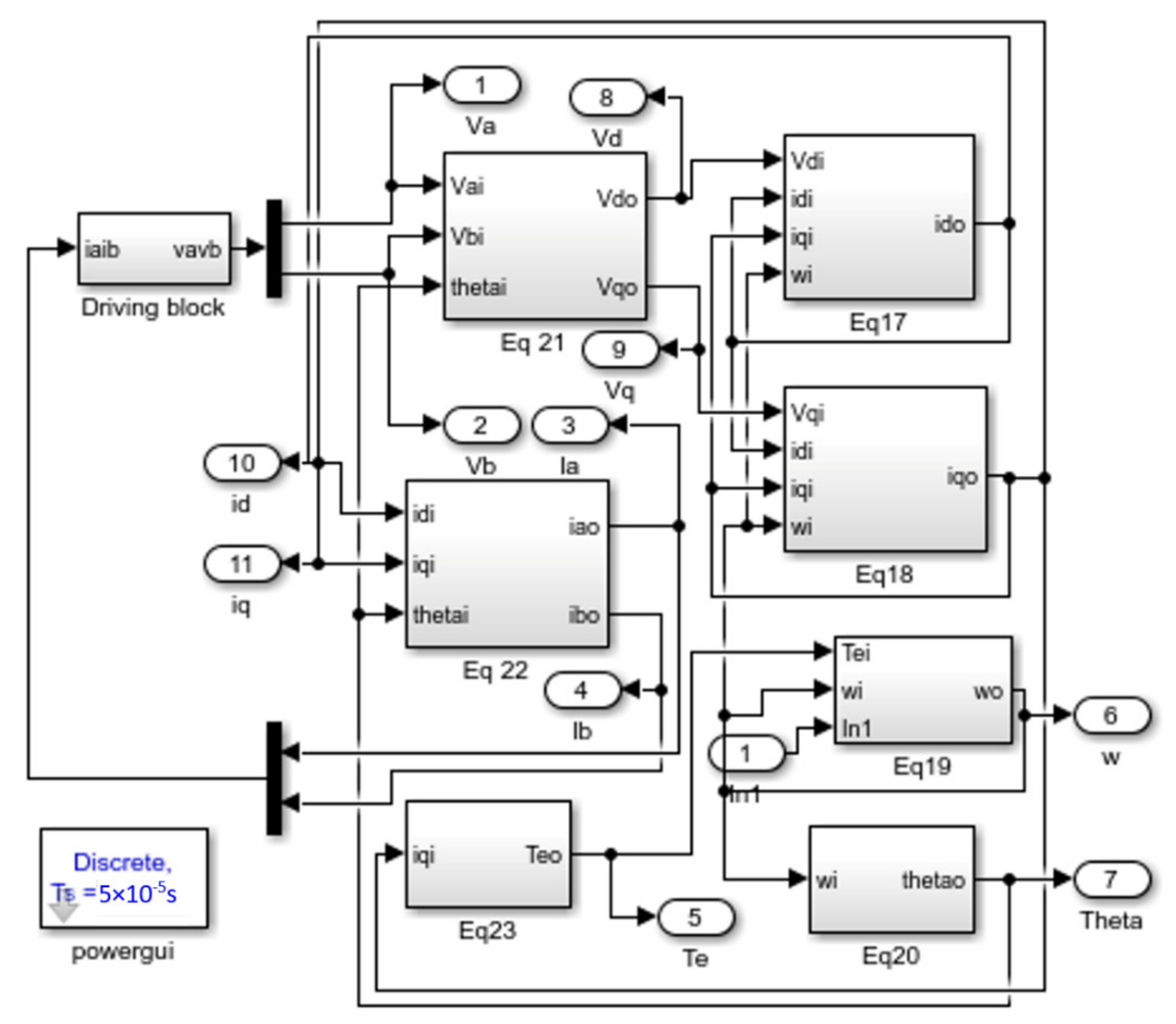
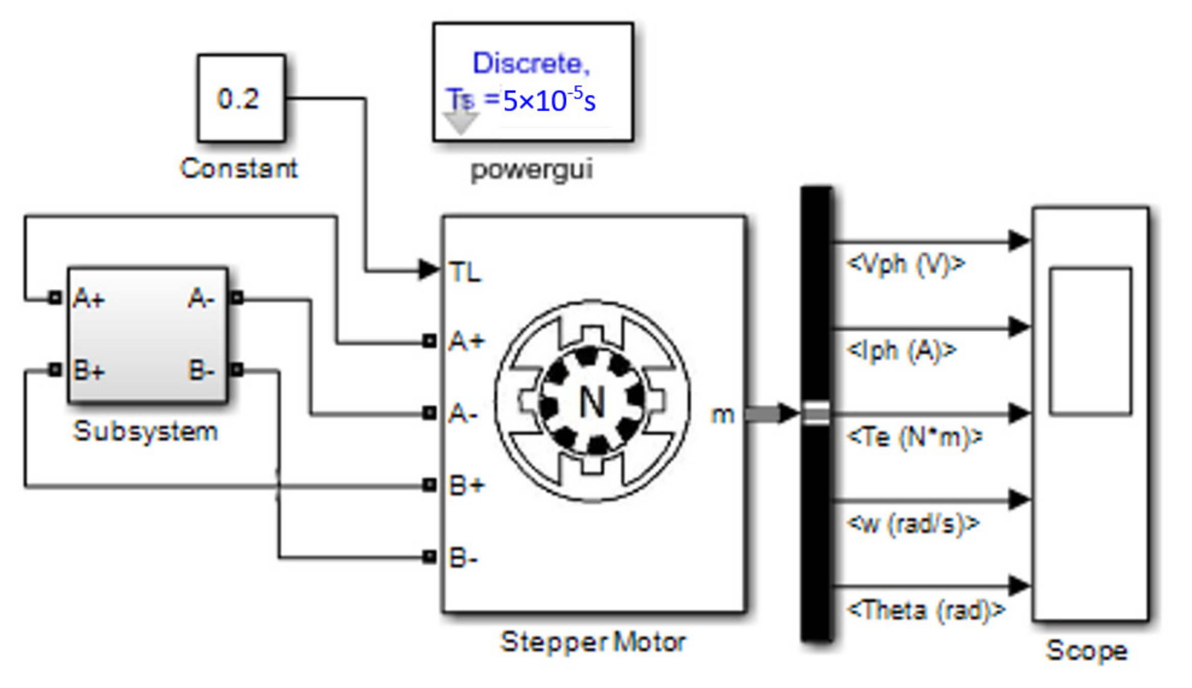
3. Simulink Dynamic Model

The equations from (1) to (16) were mathematically reformulated and simplified in Table 1 for implementing the simple Simulink model of a two-phase hybrid stepper motor. The constant values Ls and ψm are calculated by (5) and (8), respectively. The equations given in Table 1 are used to build the main block diagram of the Simulink model of motor, where this block diagram is illustrated in Figure 4. In addition, the Equations (17)–(23) shown in the block diagram are a reflection of the equation numbers given in Table 1. Figure 5 explains the content of the Driving block, which is given in Figure 4. The principle of this Driving block is based on the bipolar drive method of the stepper motor. Moreover, this driving block requires a DC pulse voltage of 24 V and feedback currents from the motor.
In order to prove the validity of the proposed model, the Simulink model given in Figure 6 and exist in the library of Matlab is used to simulate a real case motor. Additionally, the subsystem of the driving circuit of the Matlab model is like the driving circuit shown in Figure 5b. Thus, the results of the two models were compared under the same running conditions. These results and running conditions of a two-phase hybrid stepper motor are discussed in the following section.

4. Results and Discussion

The Simulink models in the previous section are examined by the two-phase hybrid stepper motor and its data given in Table 2. The bipolar method is used to drive the motor at 24 V and a time of period 0.1 s. The result illustrated in Figure 7 and Figure 8 is obtained by the proposed model, while the result shown in Figure 9 is achieved by the Simulink model of the stepper motor in the library of Matlab. Therefore, phase currents, electromagnetic torque, speed, and displacement angle were tested and compared in Figure 7 and Figure 9 for the two Simulink models in this article. Figure 7a and Figure 9a show the input phase voltage for phases α and β. The phase currents are obtained in Figure 7b by running the proposed Simulink model, whereas currents shown in Figure 9b are obtained by running the model in the Simulink libraries. The phase currents in Figure 7b are faster than the currents shown in Figure 9b to reach the steady state inside each of the steps. Moreover, the response of currents in each step is under damping in the proposed model, whereas the response is overdamping in the model of Simulink libraries. The electromagnetic torque in Figure 7c reaches an average steady-state value of 0.2014 Nm, while the torque in Figure 9c still oscillates inside each step of motor motion. Figure 7d and Figure 9b illustrate the response of speed in each step of motion. In addition, the speed in the proposed model reaches a steady-state faster than the model of Simulink libraries. The motor in eight steps theoretically gives 240 degrees. However, the result in Figure 7e at the end of the eight steps shows the angle is 193.86 degrees, whereas Figure 9e shows the angle of 192.69 degrees.
The proposed model is built dependent on dq transformation for current and voltage values. Figure 8 shows the behavior of voltage and current for axes d and q. The voltage signals are given in Figure 8a, and the current signals are given in Figure 8b. The main important parameter in this figure is the iq current because this current is directly proportional to electromagnetic torque.
Figure 10a–c is gained by simulating the proposed model, while Figure 11a–c is obtained by running the Simulink model in the library of Matlab. Thus, the speed and position angle of the stepper motor were examined and compared in Figure 10b and Figure 11b by the two models discussed in the article at load torque 0.2 Nm and voltage pulse 24 V and period 0.015 s. The figures show the speed of the motor oscillates inside the steps of motion in the two models, but the speed is faster to reach the steady-state values in the proposed one. Moreover, in Figure 10c and Figure 11c, the behavior of angle approximately indicates the motor moving in a continuous mode of operation. The motor should theoret-ically rotate 12,000 degrees after 400 steps of driving. On the other hand, after 400 steps of simulating the models, Figure 10 shows the motor rotates 11,951 degrees while Figure 11 shows the motor rotates 11,933 degrees.
Figure 12 and Figure 13 present the simulation results of electromagnetic torque, speed, and displacement angle of the stepper motor when the load torque is changed from 0.5 to 0.2 Nm. In Figure 12, the motor was driven by impulse voltage with a period of 0.4 s, whereas in Figure 13, the period of voltage is 0.1 s. The load was changed in each of two cases after the first period, as shown in figures. from these figures is concluded the steady-state placement of position angle occurs after 0.025 s after starting of each step.

5. Conclusions

This paper presents a simple mathematical and Simulink model of a two-phase hybrid stepper motor. Neglecting the permeance space harmonics of the hybrid motor is the main consideration for deriving the proposed model by using dq transformation. The simulation results proved the proposed Simulink model is more efficient than the Simulink model in the library of Matlab. Equivalent Electrical circuits of the motor were also derived in this article. Finally, the proposed mathematical, Simulink, and circuit models, can be used to ease the work of researchers in the fields of control, design, and experimental analysis of hybrid stepper motors.

Author Contributions

Formal analysis, N.A.I. and K.Y.; Funding acquisition, H.A. and A.A.; Investigation, K.Y.; Methodology, N.A.I. and K.Y.; Project administration, N.A.I.; Resources, K.Y.; Software, N.A.I. and K.Y.; Validation, N.A.I. and A.A.A.S.; Writing—original draft, N.A.I., K.Y. and K.T.; Writing—review & editing, F.M.M., H.A. and A.Q. All authors have read and agreed to the published version of the manuscript.

Funding

This research received no external funding.

Conflicts of Interest

The authors declare no conflict of interest.

Nomenclature

B total friction coefficient
Emmaximum open-circuit winding voltage
F m magnetomotive force
J total inertia
L s inductances of phase winding of steeper motor
L α , L β self-inductances of phase α and β
Nsnumber of teeth per stator pole
P in electrical input power of stepper motor
P m electromagnetic power of stepper motor
P1(x) to P5(x)permeance layers as function of length x
Pt(x)total permeance function
P n the n harmonic of permeanc function
P 1 the first harmonic of permeanc function
P α , P α ¯ , P β , P β ¯ permeance for phases of stepper motor
P ¯ average of permeance function
R s resistance of phase winding of steeper motor
T e electromagnetic torque of stepper motor
TLload torque
V d , V q voltages of stepper motor in dq axes
V α , V β voltages for phase α and phase β
i d , i q currents of stepper motor in dq axes
i α , i β currents for phase α and phase β
mphase number of motor
nmconstant speed of stepper motor at open-circuit winding voltage
pnumber of pole pairs
α, β, α ¯ , β ¯ phases of stepper motor
θ(t)displacement angle
μ 0 permeability of free space
ψmmaximum flux linkage
ψ α m , ψ β m mutual flux linkages on phases α and β
ω rotational speed of stepper motor ( d θ dt )

References

  1. Manasrah, A.; Alkhalil, S. A 2-DoF Skin Stretch Display on Palm: Effect of Stimulation Shape, Speed and Intensity. In Proceedings of the International Conference on Human Haptic Sensing and Touch Enabled Computer Applications, EuroHaptics 2020, Leiden, The Netherlands, 6–9 September 2020; pp. 12–24. [Google Scholar]
  2. Hojati, M.; Baktash, A. Design and fabrication of a new hybrid stepper motor with significant improvements in torque density. Eng. Sci. Technol. Int. J. 2021, 24, 1116–1122. [Google Scholar] [CrossRef]
  3. Hamid, N.A.; Abdelrahim, A.; Ahmed, M.M. Developing the Hybrid Stepper Motor Model for Tracking Purpose Using New Methodology. In Proceedings of the International Workshop on Materials, Chemistry and Engineering—IWMCE, Xiamen, China, 16–17 June 2018; pp. 174–182. [Google Scholar] [CrossRef]
  4. Lai, C.-K.; Lin, B.-W.; Lai, H.-Y.; Chen, G.-Y. FPGA-Based Hybrid Stepper Motor Drive System Design by Variable Structure Control. Actuators 2021, 10, 113. [Google Scholar] [CrossRef]
  5. Ionică, I.; Modreanu, M.; Morega, A.; Boboc, C. Design and Modeling of a Hybrid Stepper Motor. In Proceedings of the 2017 10th International Symposium on Advanced Topics in Electrical Engineering (ATEE), Bucharest, Romania, 23–25 March 2017. [Google Scholar]
  6. Mihalache, G.; Zbant, A.; Livint, G. Open-Loop Control of Hybrid Stepper Motor with Two Phases Using Voltage to Fre-quency Converter. In Proceedings of the 2013 8th International Symposium on Advanced Topics in Electrical Engineering (ATEE), Bucharest, Romania, 23–25 March 2013. [Google Scholar]
  7. Kuert, C.; Jufer, M.; Perriard, Y. New method for dynamic modeling of hybrid stepping motors. In Proceedings of the Conference Record of the 2002 IEEE Industry Applications Conference. 37th IAS Annual Meeting (Cat. No.02CH37344), Pittsburgh, PA, USA, 13–18 October 2002. [Google Scholar]
  8. Chai, H. A mathematical model for single-stack step motors. IEEE Trans. Power Appar. Syst. 1975, 94, 1508–1517. [Google Scholar] [CrossRef]
  9. Rao, E.S.; Prasad, P. Dynamic Performance Analysis of Permanent Magnet Hybrid Stepper Motor by Transfer Function Model for Different Design Topologies. Int. J. Electr. Comput. Eng. 2011, 2, 191–196. [Google Scholar] [CrossRef]
  10. Matsui, N.; Nakamura, M.; Kosaka, T. Instantaneous torque analysis of hybrid stepping motor. IEEE Trans. Ind. Appl. 1996, 32, 1176–1182. [Google Scholar] [CrossRef]
  11. Mizutami, K.; Hayashi, S.; Matsui, N. Modeling and control of hybrid stepping motors. In Proceedings of the Conference Record of the 1993 IEEE Industry Applications Conference Twenty-Eighth IAS Annual Meeting, Toronto, ON, Canada, 2–8 October 1993. [Google Scholar]
  12. Bendjedia, M.; Ait-Amirat, Y.; Walther, B.; Berthon, A. Position Control of a Sensorless Stepper Motor. IEEE Trans. Power Electron. 2011, 27, 578–587. [Google Scholar] [CrossRef]
  13. Le-Huy, H.; Brunelle, P.; Sybille, G. Design and implementation of a versatile stepper motor model for simulinks SimPowerSystems. In Proceedings of the IEEE International Symposium on Industrial Electronics (ISIE), Cairns, QLD, Australia, 13–15 June 2008; pp. 437–442. [Google Scholar] [CrossRef]
  14. Samokhvalov, D.; Stoliarov, S.; Kekkonen, A. The hybrid stepper motor modeling in Simulink. In Proceedings of the 2015 IEEE NW Russia Young Researchers in Electrical and Electronic Engineering Conference (EIConRusNW), St. Petersburg, Russia, 2–4 February 2015. [Google Scholar]
  15. Morar, A. The Modelling and Simulation of Bipolar Hybrid Stepping Motor by Matlab/Simulink. Procedia Technol. 2015, 19, 576–583. [Google Scholar] [CrossRef]
  16. Lin, H.; Anatolii, S.; Naung, Y.; Zaw, K.; Khaing, Z. Modelling and control of an open-loop stepper motor in Matlab/Simulink. In Proceedings of the 2017 IEEE Conference of Russian Young Researchers in Electrical and Electronic Engineering (EIConRus), Moscow, Russia, 1–3 February 2017. [Google Scholar]
  17. Iqteit, N.A.; Daud, A.K. A new model of self-excited induction generator to feed a single phase load with an application in lighting animal farm. Int. J. Power Energy Convers. 2019, 10, 32. [Google Scholar] [CrossRef]
  18. Ong, C. Dynamic Simulation of Electric Machinery; Prentice Hall PTR: Hoboken, NJ, USA, 1998. [Google Scholar]
  19. Ullah, N.; Khan, F.; Ullah, W.; Basit, A.; Umair, M.; Khattak, Z. Analytical Modelling of Open-Circuit Flux Linkage, Cogging Torque and Electromagnetic Torque for Design of Switched Flux Permanent Magnet Machine. J. Magn. 2018, 23, 253–266. [Google Scholar] [CrossRef]
  20. Sheth, N.; Rajagopal, K. Calculation of the flux-linkage characteristics of a switched reluctance motor by flux tube method. IEEE Trans. Magn. 2005, 41, 4069–4071. [Google Scholar] [CrossRef]
  21. Agha, A.; Attar, H.; Luhach, A.K. Optimized Economic Loading of Distribution Transformers Using Minimum Energy Loss Computing. Math. Probl. Eng. 2021, 9, 2021. [Google Scholar] [CrossRef]
  22. Morimoto, S.; Takeda, Y.; Hirasa, T. Current phase control methods for permanent magnet synchronous motors. IEEE Trans. Power Electron. 1990, 5, 133–139. [Google Scholar] [CrossRef]
Figure 1. Linearized tooth-to-tooth of stepper motor and the path of fluxes [9,10].
Energies 15 06159 g001
Figure 2. Cross-section of stepper motor and dq axes.
Energies 15 06159 g002
Figure 3. Circuit model of stepper motor (a) for d axis, (b) for q axis.
Energies 15 06159 g003
Figure 4. Proposed Simulink model of two-phase Hybrid Stepper Motor.
Energies 15 06159 g004
Figure 5. (a) Content of the “Driving block” in Figure 4, (b) Content of the “subsystem” in (a).
Energies 15 06159 g005
Figure 6. The stepper motor model existing the Simulink libraries of Matlab.
Energies 15 06159 g006
Figure 7. Results of proposed model at TL = 0.2 Nm and period of time 0.1 s: (a) Va (blue) Vb (red), (b) Ia (blue) Ib (red), (c) electromagnetic torque, (d) speed, and (e) displacement angle.
Energies 15 06159 g007
Figure 8. Voltage and current of the stepper motor in axes of d and q.
Energies 15 06159 g008
Figure 9. Results of the model in the Simulink libraries at TL = 0.2 Nm and period of time 0.1 s, (a) Va (yellow) Vb (blue), (b) Ia (yellow) Ib (blue), (c) electromagnetic torque, (d) speed, and (e) displacement angle.
Energies 15 06159 g009
Figure 10. Results of proposed model at TL = 0.2 Nm and period of time 0.015 s: (a) phase voltages, (b) speed, and (c) displacement angle.
Energies 15 06159 g010
Figure 11. Results of the model in the Simulink libraries at TL = 0.2 Nm and period of time 0.015 s: (a) phase voltages, (b) speed, and (c) displacement angle.
Energies 15 06159 g011
Figure 12. Characteristic of stepper motor at period signal 0.4 s and changing load torque from 0.5 to 0.2 Nm.
Energies 15 06159 g012
Figure 13. Characteristic of stepper motor at period signal 0.1 s and changing load torque from 0.5 to 0.2 Nm.
Energies 15 06159 g013
Table 1. Summarized equations for proposed Simulink model.
EquationNo.
i d = 1 L s V d R s i d + p ω L s i q d t (17)
i q = 1 L s V q R s i q p ω L s i d p ψ m ω d t (18)
ω = 1 J ( T e B ω T L ) d t (19)
θ = ω d t + θ 0 (20)
V d = V α cos p θ + V β sin p θ
V q = V α sin p θ + V β cos p θ
(21)
i α = i d cos p θ i q sin p θ
i β = i d sin p θ + i q cos p θ
(22)
T e = p ψ m i q (23)
where the constant values are : L s = 4 P ¯ N s 2 ,   ψ m = 30 π E m n
Table 2. Data of two-phase hybrid stepper motor.
Number of Phases2
Winding Inductance (Ls)1 mH
Winding Resistance (R)1.2 Ω
Step Angle30°
The maximum flux linkage (ψm)0.04 Vs
Loading Torque (TL)0.2 Nm
Total inertia (J)2 × 10⁻⁵ kg·m2
Total friction (B)1 × 10⁻³ kg·m/s
θ0 and ω00
Publisher’s Note: MDPI stays neutral with regard to jurisdictional claims in published maps and institutional affiliations.

