Review

A Review on Magnet Loss Analysis, Validation, Design Considerations, and Reduction Strategies in Permanent Magnet Synchronous Motors

by
Samith Sirimanna
*,
Thanatheepan Balachandran
and
Kiruba Haran
Department of Electrical Computer Engineering, University of Illinois at Urbana Champaign, Urbana, IL 61801, USA
*
Author to whom correspondence should be addressed.
Energies 2022, 15(17), 6116; https://doi.org/10.3390/en15176116
Submission received: 1 August 2022 / Revised: 20 August 2022 / Accepted: 20 August 2022 / Published: 23 August 2022
(This article belongs to the Topic Designs and Drive Control of Electromechanical Machines)

Abstract

:
Eddy current losses in magnets are a major consideration in the rotor design of permanent magnet synchronous motors (PMSMs). Stator design choices and the use of modern inverters with high switching frequency introduce harmonics that can contribute to significant losses in the magnets, causing the rotor to heat up. In typical PMSMs, the lack of rotor cooling can cause the magnet’s performance to degrade at high temperatures and eventually demagnetize. This review examines a large number of studies analyzing magnet eddy current losses using analytical methods and finite-element analysis. In some of these studies, magnet segmentation is carried out to reduce the losses; however, their loss-reduction effects depend highly on the type of PMSM and the mix of stator harmonics. Magnet segmentation without considering these effects can, in fact, increase the magnet losses, in addition to the extra manufacturing efforts. Multiple design analysis show the influence of rotor–stator geometric features on magnet losses. Although measuring magnet eddy current losses for these motor designs is a tedious task, authors have proposed calorimetric and loss segregation-based techniques to provide validation. This paper addresses magnet loss modeling techniques, PM material considerations, magnet segmentation effectiveness, motor and stator design effects, and experimental validation to inform motor designers about the costs and benefits of rotor designs that minimize rotor losses.

1. Introduction

High-frequency permanent magnet (PM) motor drives are becoming increasingly available in electric vehicles (EV), aerospace, and other applications which are sensitive to motor weight. Designing these machines encompasses multiple strategies such as distributed vs. concentrated windings on the stator and interior PM, surface PM, and inset PM on the rotor. Independent of design choice, the magnets in the rotor are exposed to a variety of harmonics. They are generated from the slotting effect and inverter switching and are the sources of magnet eddy current losses. Typically, stator slotting produces the first few harmonics, while modern inverters create pulse-width modulation (PWM) switching harmonics that have significantly higher frequencies. The percentage of eddy current losses due to each of these sources may vary depending on stator and rotor design. Popular NdFeB magnets used in most of these applications have a high electrical conductivity that exhibits eddy currents and creates eddy current losses. While the magnitude of this loss component is typically low compared to major losses such as copper, iron, and mechanical losses, and has a lower impact on motor efficiency, excessive losses generated in thermally isolated rotors develop barriers to the continuous operation and lead to thermal magnetic degradation.
Magnet segmentation increases the resistance of eddy current paths and is the prevailing strategy to reduce eddy current losses. Segmentation can be either axial or circumferential. The former is more common in longer stack-length machines and, additionally, benefits the manufacturability of magnets by providing a practical dimensional aspect ratio. The latter is implemented to further curtail the magnet losses. During high-speed operation, when these harmonic frequencies approach the kHz range, typical NdFeB magnet blocks reach their skin depth, such that the eddy currents are concentrated on the magnet edges. Here, the skin depth ( δ ) is defined as:
δ = 2 σ ω μ
where σ is the material’s electrical conductivity, ω is the angular frequency, and μ is the material’s permeability. As the frequencies increase to a level that makes skin depth close to half the magnet width, the circuit transitions from a resistance-limited to a reactance-limited circuit, causing the more segmented magnet to generate more losses [1]. Of the two indispensable methods used to model magnet losses, finite-element analysis (FEA) and analytical, FEA better captures the skin effect. While there are several analytical models that incorporate the skin effect, some of them are constrained to a homogeneous or sinusoidal excitation field.
This paper aims to summarize the modeling techniques and various factors affecting magnet losses in PM motors to provide motor designers with design approaches that can minimize rotor magnet losses. Section 2 details the two main mechanisms, hysteresis and eddy currents, that generate magnet losses; methods used in analyzing the eddy current loss; analytical models, and their ability to predict the losses. Section 2.3 describes a simple case study used to investigate the accuracy of a few selected methods. Section 3 describes the PM material properties that influence the losses and provides a comparison between the most common PM materials. Section 4 presents segmentation effects and summarizes findings from the literature. Section 5 investigates the variation of magnet losses in PMSMs due to rotor design and discusses features of available rotor types contributing to magnet eddy current losses. The influence of stator design choices and winding types is outlined in Section 6, while Section 7 summarizes other possible factors that contribute to magnet losses. Section 8 reports on experimental validation mechanisms using calorimetric and loss segregation approaches and their results.

2. Loss Mechanism and Modeling Techniques

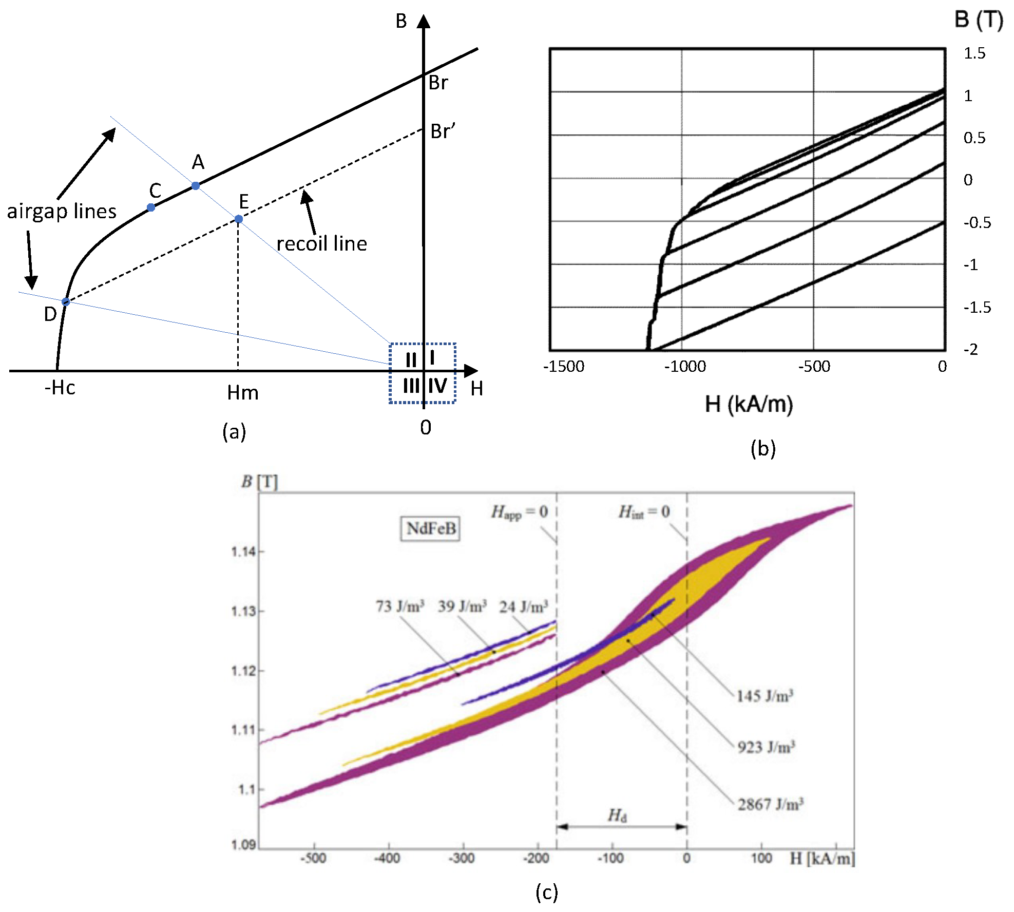
2.1. Hysteresis Loss

Two potential loss mechanisms in magnets are hysteresis and eddy current losses. Although the majority of the magnet loss studies in the literature focus only on eddy current losses, rare-earth magnets in PMSMs are electrically conductive metal blocks with permeability slightly higher than air ( μ 0 ); thus, there is the possibility of developing hysteresis loops.
Figure 1a shows the normal curve between the applied magnetic field (H) and the magnetic flux density (B) of a rare-earth PM material. On the original curve, the segment from Br to point C is called the linear region where point C is called the knee point. After the knee point, the flux density drops gradually and becomes zero when the applied magnetic field is equal to coercivity (Hc). The operating point will be at the intersection of the BH curve and the airgap line (determined by whichever application is being modeled), e.g., point A. In a PMSM, this always occurs inside the second quadrant of the BH curve. If the operating point falls below the knee point, as shown in point D, the magnetic flux density does not return to its original value; rather it follows a new path set out by the recoil line. Consider the operating point represented by point E. During motor operation, a positive and negative magnetic field will be applied around Hm, which will cause the flux to vary along this recoil line. In most designs, this variation will take place within the second quadrant of the BH curve. Thus, it has the possibility of forming a loop, as seen in ferromagnetic materials. This is called a minor hysteresis loop. Capturing these minor loops requires special measuring equipment such as a vibrating sample magnetometer or a fluxgate magnetometer. Much of the literature does not report the relatively smaller minor loops (Figure 1b), while some authors have tediously tested this, as shown in Figure 1c. In any case, the relative recoil permeability of sintered NdFeB magnets is close to one, which, according to some studies [2], generates minimal magnet hysteresis losses in a typical PMSM. If the entire magnet is enclosed by the second quadrant, relatively smaller losses are present, as seen from smaller minor loops in Figure 1c.
The hysteresis losses due to slot harmonics are reported in [5], which provides details on possible scenarios for significant magnet hysteresis loss in PMSM. Changing the sign of magnetic field H is stated as the necessary condition for sizable minor hysteresis loops to form. This causes the operating condition to change from the second to the first quadrant of the BH curve as shown by the larger loops in Figure 1c. FEA modeling of a two-pole high torque PMSM shows that a strong stator field is needed for the operating point to move to the first quadrant of a rare earth magnet [4]. This can easily be avoided with careful consideration at the machine design stage. In summary, hysteresis losses in rare-earth magnets seem to be smaller or avoidable.

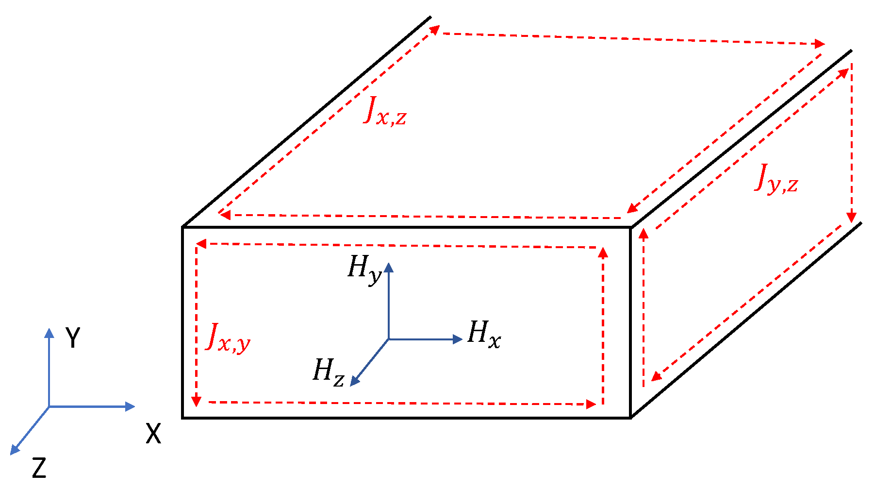
2.2. Eddy Current Loss

FEA modeling is frequently used at the machine design stage as well as for loss-component analysis. It can provide a very accurate prediction of PM eddy current losses by capturing both non-homogeneous field distribution and temporal variations for any shape of the excitation waveform. Although, depending on the simulated frequency, the mesh size and time step necessary to capture the skin effect can make the FEA solution too time consuming compared to an analytical model. The solution is obtained by numerically solving the following equations [6]:
× ( 1 μ × A ) = J a σ ( A t + ϕ ) + 1 μ 0 × M
· ( σ ( A t + ϕ ) ) = 0
V a = d Φ d t + R a i a
where A and ϕ are the magnetic vector potential and electric scalar potential, respectively, J a is the armature current density, and M is the PM magnetization. v a and i a are the armature voltage and current, respectively, where the R a and Φ are the armature resistance and flux linkage, respectively. Numerous studies have analyzed the magnet losses using FEA both in 2D and 3D domains [7,8,9,10] and hybrid methods have employed both analytical and FEA to increase computational efficiency [11,12,13].
The 2D analytical methods predicting the magnet eddy current losses can be derived from basic Maxwell equations and PM material characteristics. The governing Helmholtz equation for magnet losses can be derived using
B = μ m ( H + M )
× E = B t
J = × H
J = σ m E
· B = 0
where B is the magnetic flux density, E is the induced electric field using Faraday’s law, H is the magnetic field, J is the eddy current density in the magnet, and μ m and σ m represent magnet permeability and electrical conductivity, respectively. Applying Equations (6) and (7) along with boundary conditions gives
2 H = μ m σ m H t
The skin depth is much larger than the typical magnet block dimensions under relatively lower frequencies. This removes the need for considering magnet eddy current reaction field effects. The majority of the models do not capture this reaction field, and are called resistance-limited models [14,15,16,17,18,19,20,21,22,23,24,25,26]. At relatively higher frequencies, the skin depth becomes important to the eddy current loss calculations. This causes a significant reaction field on the magnet and, as a result, the magnet losses vs. frequency flatten. A few analytical models that are referred to as skin-limited models capture this effect [6,27,28,29,30,31,32,33,34,35,36]. Given the high-frequency nature of modern motor drives, skin-limited models are more suitable. Another important factor is the excitation field distribution; this could be spatially homogeneous or non-homogeneous. Some of these models display accurate modeling of eddy current losses with reaction field under a spatially homogeneous field excitation [6,27]. A few studies are available that used analytical methods that capture the non-homogeneity of the excitation field in a 3D domain, both excluding the reaction field [37,38,39] and including it [40,41].
Accurate modeling of the stator field is equally important to properly model the field excitation source, which is spatially non-homogeneous. Analytical modeling of stator magnetic fields in electric machines has been largely improved in past decades. Stator field modeling techniques for slotless stators are summarized in [42,43]. For the slotted stators, the modeling methods include reluctance networks [44,45,46,47], conformal mapping [48,49], and subdomain and exact subdomain methods [50], where the subdomain methods are more commonly used. In most 2D analytical models, only the normal magnetic field component H y is considered as the source for eddy current loss. This results in eddy currents in the x-z plane, flowing in the x and z directions. In a typical PMSM, the magnet block experiences both normal ( H y ) and tangential magnetic field ( H x ) due to stator harmonics. Three-dimensional methods capture the effects of the magnetic field in all x, y, and z directions, which creates eddy currents in all x-z, x-y, and y-z planes, as shown in Figure 2. The depiction of eddy current paths here is only representative of the loop they flow in. The actual depth of penetration of the currents will depend on the magnet block dimensions and operating frequency.
Next, two forms of magnet loss expressions with different levels of complexity will be described. These will be applied in a simple study later in Section 2.3. A basic form of the equation, which considers a homogeneous magnetic field excitation through the magnet block, can be written using the iron-loss equations as [1]:
P v = π 2 f 2 B m 2 a 2 6 ρ
where f is the excitation frequency, B m is the mean flux density through the block in the y-direction, a is the magnet width, and ρ is the magnet resistivity. One limitation in this type of modeling is the failure to capture the skin effect, which will cause the losses to keep growing as the frequency increases. As the frequency increases, the magnetic field through the magnet block starts to fringe, which invalidates the homogeneous field assumption.
The 2D analytical model described in [6] finds the field solution to the governing Helmholtz equation:
H y 2 ( x , z ) x 2 + H y 2 ( x , z ) z 2 = j ω μ σ H y ( x , y ) )
and uses
J ( x , z ) = × H y ( x , z )
to arrive at a spatial distribution of current densities in the x-z plane as
J x ( x , z ) = 8 a γ 2 H π 2 n = 1 ( 1 ) m λ m ( 2 m + 1 ) 2 β m s i n h ( β m z ) c o s h ( β m b ) c o s ( λ m x )
J z ( x , z ) = γ H s i n h γ x c o s h γ a + 8 a γ 2 H π 2 m = 1 ( 1 ) m λ m ( 2 m + 1 ) 2 β m 2 c o s h h ( β m z ) c o s h ( β m b ) c o s ( λ m x )
where γ , λ m , and β m are parameters that can be calculated using skin depth, magnet width (a), and the spatial harmonic order (m). Compared to the simple loss equation, this method calculates the positional magnetic field and current density variation to capture the field non-homogeneity on the magnet. Current densities and material conductivity can be used to calculate the loss as in (16).
P = 2 d σ 0 a 0 b J x ( x , y ) 2 + J z ( x , y ) 2 d x d y

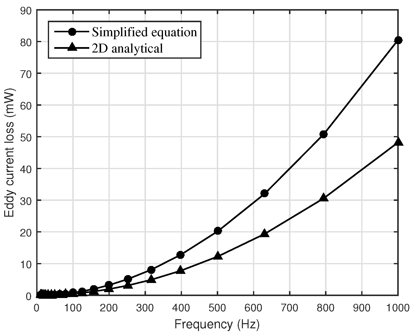
2.3. A Comparison Study

Typical EV motor drives involve inverters with 10–20 kHz switching frequency and can create significant stator current harmonics up to a few times the switching frequency. Thus, it is useful to understand the eddy current losses generated in a magnet block under a wide range of frequency excitation before applying models to the motor application. In order to demonstrate key highlights of this behavior, two magnetic circuits with and without an airgap are used, as shown in Figure 3. These consist of two cut C-cores with a magnet placed in between. The C-core has the cross section dimensions shown in Figure 3, derived from a standard Metglass Amorphous core size to contain the flux path through the magnet block. For the gapped core on left, a gap of 16 mm (8 mm from each C-core) was taken out to place the magnet in the middle of the airgap. This leaves an airgap of 4.7 mm on each side of the magnet. For the ungapped core, only 3.3 mm was taken out from each core, to fit the magnet exactly between them. The magnet block dimensions are taken from a typical hybrid EV motor design [51] as 6.6 mm height, 19.1 mm width, and 30.5 mm depth on the z-axis. The motor in this reference is using sintered NdFeB magnets. Thus, the sample is assumed to have a representative electrical conductivity of 0.66 MS/m and relative permeability of 1.05. For the purpose of comparison, a pure sinusoidal excitation of 100 amp-turns is applied to the excitation coil in each circuit.
Figure 4 shows the loss comparison between the simple approach in (11) and the described 2D analytical method in [6] for the gapped-core magnetic circuit. As seen, the simple homogeneous assumption without skin effect is already predicting much higher losses in the frequency range of hundreds of Hz. The plot shows the predicted loss difference in the lower frequency range, where the 2D analytical model has not yet reached the frequencies that would permit skin effect.
Figure 5 gives a comparison of loss prediction between 2D analytical and FEA methods. Both models show the skin effect, which causes the loss rate to decline. At first, the magnet losses increase as the square of the frequency. When the frequency is large enough, the skin effect becomes significant, and the circuit moves from being resistance-limited to reactance-limited [18], causing the loss rate to flatten. Here, the increase is proportional to the square root of the frequency. The exact frequency at which this transition occurs will depend on magnet dimensions and magnetic circuit parameters. Roughly, it initiates around the frequency that makes δ = 2a, where a is the magnet width.
In the ungapped core magnetic circuit, the analytical model and FEA are close to each other. This circuit has a lower magnetic reluctance, which will generate a higher magnetic field and higher losses when the same excitation is applied. However, at higher frequencies, the magnetic circuit with an airgap shows lower losses from the analytical model than from FEA. This is caused by assuming a normal magnetic field ( H y ) in the analytical model, a state that is less true than in the ungapped core because of flux fringing. Similarly, depending on the application, analytical models can vary in accuracy, despite faster calculation. A similar comparison is provided in [52], which compares increasingly complex analytical models with the FEA solution, and presents recommendations on which models are more accurate for a given excitation frequency.

3. Material Properties

PM material properties such as electrical conductivity and permeability influence eddy current loss behaviors. Although the NdFeB magnets are the more common choice in most modern PM motors, other magnets such as Sm-Co magnets are preferred in some motor applications, where a higher temperature rating is required. Alnico magnets with inherently lower coercivity are less popular now in motor applications due to the superior rare-earth magnets, although, new grades of Alnico magnets are still used in some motor designs. When it comes to manufacturing, NdFeB magnets have two production methods: sintered and bonded. In the case of a sintered magnet, the pulverized material is heat treated to form the required shape, while in the bonded magnets pulverized particles are mixed with a polymer and formed using injection molding or a similar process. Sintered NdFeB magnets have varying electrical conductivity from around 0.5 MS/m to 0.9 MS/m, depending on the material grade and manufacturing process, while providing a relative permeability of around 1.05. Figure 6 shows the eddy current loss variation of sintered NdFeB magnets based on their conductivity. The same gapped magnetic circuit was used as in Section 2.3. The lowest magnetic conductivity, although it has lower losses at relatively lower frequencies, ends up generating more losses at higher frequencies.
Next, the loss variation due to the difference in PM permeability is investigated using a few grades of bonded NdFeB magnets. They exhibit a wide range of permeability values while the conductivity is consistently an order of magnitude lower compared to sintered magnets. Figure 7 shows the loss behavior of three different classes of bonded magnets with the same electrical conductivity of 0.01 MS/m and varying permeability. Due to the lower conductivity, the loss saturation takes place at a much higher frequency than in the sintered magnet. Thus, the effect on losses due to permeability variation is minimum within available bonded NdFeB magnet grades.
An overall comparison is conducted next. The comparison in Figure 8 shows the eddy current losses of magnet blocks of the same dimensions with different materials subjected to the same current excitation. As shown in Table 1, the electrical conductivity largely varies between the available types of magnet, and the permeability difference is relatively low. As for other familiar magnet types, ceramic magnets are not included here due to the huge electrical resistivity it displays. For a given magnet block size, the material properties result in better loss characteristics for certain frequency ranges. Although the magnet material, manufacturing method, and their grade impact magnet eddy current losses, the selection of material is governed by specifications such as remnant flux density ( B r ), maximum energy product ( B H m a x ), coercivity ( H c ), and temperature ratings. Thus, in most cases, the physical properties of the magnet are typically a lower priority in design consideration.

4. Segmentation Effects

Magnet segmentation is the prevailing strategy to cut down magnet eddy current losses in PM machines. The main idea behind segmentation is to build up the effective resistance of eddy current paths, such that the losses will effectively decrease. This method reduces losses when the excitation frequencies are relatively lower and the skin effect has not taken effect. Several analytical models describe how to analyze magnet segmentation in PMSM loss models [1,6,16,23].
First, the focus will be on circumferential segmentation. In a typical PM motor drive with a voltage source inverter (VSI), the excitation harmonics will be voltages, which will naturally dampen the losses corresponding to high-frequency harmonics by reactive impedance. Although, to provide a simplified explanation of circumferential segmentation, the same FEA magnetic circuit from Section 2.3 is used here with constant current excitation. As can be seen from Figure 9, the skin effect reverses the loss reduction expected by circumferential segmentation, also known as the anomaly of segmentation [1]. Because of this, the segmentation corresponding to the lowest eddy current loss depends on the frequency of interest. For this particular magnetic circuit, any level of segmentation is effective in reducing losses due to harmonics below 30 kHz. In an EV drive, this frequency range will correspond to the PWM harmonics from the inverter. Usually, the stator harmonics due to the slots will be of much lower frequency and will be effectively reduced by segmentation, although the loss magnitude may be small.
Axial magnet segmentation is frequently found in PMSMs. In a relatively longer stack length motor, the level of axial segmentation can create differences in the eddy current reaction field due to the available eddy current path. This can demonstrate anomaly of segmentation, as will be discussed with an example in Section 5. Overall, the effective loss reduction due to magnet segmentation depends on many factors such as the spectrum of harmonics, magnet dimensions, magnetic circuit, and magnet material, and cannot be determined without a detailed look into the particular PMSM drive subsystem and operating conditions [6,14,16,23,54,55,56].
The contact resistance between the segmented magnets is studied in [57]. It analyzes the component level factors contributing to the effectiveness of segmentation such as the stress between the bonded sintered magnet segments. The results validated that the eddy currents pass through the contact when the compressive force is large, highlighting the importance of manufacturing precision.

5. Rotor Types

There are mainly three rotor types that are used in PM motor designs: surface, interior, and inset. The EV industry is highly focused on interior permanent magnet (IPM) motors due to a variety of reasons including variable speed profiles, requirements for field weakening, and fault tolerance. Some applications that demand constant load profiles, such as aerospace, prefer surface-mount permanent magnet (SPM) motors. Depending on the rotor type, studies show that flux variation on the magnet can vary. FEA results in [58] demonstrate that in low-frequency SPM (<1 kHz), the mid magnet sections experience lower field variation compared to a magnet section facing the airgap. In higher frequency harmonics, the field typically penetrates the entire magnet depth. Due to this reason, the percentage of magnet eddy current losses due to slot harmonics in SPM will be higher than in IPM.
Unlike in SPM, the IPM magnets are buried inside the rotor iron and are not directly exposed to the stator mmf variation by slot harmonics. Although, the PWM harmonics will clearly penetrate the magnets and will create eddy current losses in both cases of IPM and SPM. The analysis in [59] shows the eddy current paths in SPM magnets flow in small loops, which corresponds to the slot openings as shown in Figure 10. This is different in the case of IPM, where the eddy currents flow in a larger loop that covers the entire magnet. While carrier harmonics losses are almost the same for both, the SPM shows significantly higher losses due to slot harmonics at this given loading condition. The authors use an equivalent magnetic circuit to identify the main source of magnet losses in IPM; the main reason being the variation in magnetic path, where the permeance distribution in SPM is almost uniform. Thus, the main source for SPM magnet losses is deduced to be the regional variation of the flux density due to stator slot opening.
An example of total magnetic field decomposition for different rotor types into magnetization flux, armature flux, and reaction flux is presented in [60]. It shows that the ratio of reaction field to total flux is relatively large in IPM. Rotor iron next to the magnet block on each side of IPM makes the skin effect stronger and it causes the anomaly of segmentation to occur for the carrier harmonic frequencies. Magnet eddy current loss versus the axial segmentation in Figure 11 shows the continuously decreasing losses for increasing segmentation for both rotor shapes under slot harmonics. Expectedly, the carrier harmonics affect the two rotors differently. While the SPM total magnet losses decrease continuously with axial segmentation, the losses in IPM and inset PM rotors peak at a certain segmentation before it starts to decrease.
Although the SPM does not show the anomaly under these particular design and operating conditions, the analysis of SPM magnet eddy current losses in [1] shows the same anomaly in segmentation at slot harmonic frequencies for a locked rotor test.
Magnet eddy current losses are highly sensitive to the stator-rotor geometry. Optimizing the teeth shape to reduce the magnet eddy current losses is discussed in [61]. Various other modifications have been proposed such as flux barriers blocking either d or q axis flux [62] and adding grooves on rotor surface to reduce the harmonic content [63] from stator mmf.

6. Stator and Winding Type

Understanding the magnet loss behavior requires knowledge of the stator winding configuration: concentrated vs. distributed, in addition to the operating frequency, current angle, and loading. A comparison of two identical IPM rotors, each with with a distributed vs. concentrated stator is presented in [59]. As the increasing current angle reduces the operating torque, the magnet eddy current losses vary as it changes the amount of stator flux coupling with magnets. Total magnet eddy current losses are more than ten times larger for concentrated winding compared to the distributed due to large slot harmonics. Only a minor loss difference exists between the two under the carrier harmonics. For the distributed windings, loss due to slot harmonics is much smaller than that from carrier harmonics. The FEA figures show the deep penetration of slot harmonic fields to the rotor in a concentrated machine, due to wide slot pitch, while the same in distributed machine exists at the rotor surface. A comparison of magnet eddy current losses between three winding methods of fractional slot concentrated windings is presented in [15]. It investigates three possible winding methods for a 12 slot/10 pole stator with a surface PM rotor that utilizes the same stator mmf for torque production. The results show the different harmonics contributing to losses in ‘all teeth-wound’ and ‘alternate teeth-wound’. The losses are highest for the ‘alternate teeth-wound’ design with wider stator teeth. Employing the same slot/pole combination and a new winding pattern involving a different number of turns per coil side, Ref. [64] shows the magnet eddy current losses can be reduced by 80% compared to the previous base design. This is done by minimizing the space harmonics that contribute significantly to the magnet losses in a concentrated winding machine.
Modifications of rotor shapes have been performed to optimize the operation under given winding configurations. An analysis of a fractional slot IPM for loss minimization is presented in [62] with a comparison between four rotor design modifications. A slit in the rotor as a flux barrier in the q-axis generates the lowest magnet losses. The loss behavior and loss reduction effects for two motors with fractional slot numbers are investigated in [14], which analyzes a three-phase external rotor machine and a six-phase fault-tolerant machine. It shows loss reduction effects in a three-phase machine with a fault-tolerant stator than in the six-phase external rotor machine. A novel structure of SPM with damping rings is proposed in [65] to reduce eddy current losses in magnets and rotor sleeves. The trade-off between different slot/pole combinations and the loss reduction effects by multi-layer winding in fractional slot machines are shown in [66].

7. Other Considerations in Loss Reduction

As discussed, the carrier harmonics from the inverter contribute to the magnet eddy current losses, based on the stator–rotor design. The study in [67] proposed modifying the magnet shape along with the employed PWM technique to reduce the harmonic content in the back-emf waveform, which can reduce harmonic content. A similar idea is followed in [63] by adding grooves to the rotor iron while optimizing with the PWM technique to reduce the harmonic content. Variation of magnet and other loss components based on switching frequency and the inverter topology is discussed in [68], which shows the slight loss reduction from two-level to three-level inverter topology. A study was done with a two-level inverter using three types of switching devices [69]: Si IGBT (10 kHz), GaN (30 kHz), and SiC (30 kHz), that shows the harmonics distribution under three cases that cause much lower PM eddy current losses in high switching frequency inverters.
A major goal of reducing magnet losses is to limit rotor heating, which could potentially lead to magnet degradation. The heat transfer and contact resistance between the magnet block and the rest of the rotor are important to make sure the magnets are able to dissipate the heat to the entire magnet quickly without creating a local hotspot [70,71]. Thermal analysis of an IPM is conducted in [72] by considering the contact resistance of magnets. Analysis of the insulation between divided magnet segments is presented in [32], which shows the impact of insulation layer resistivity on magnet loss composition.

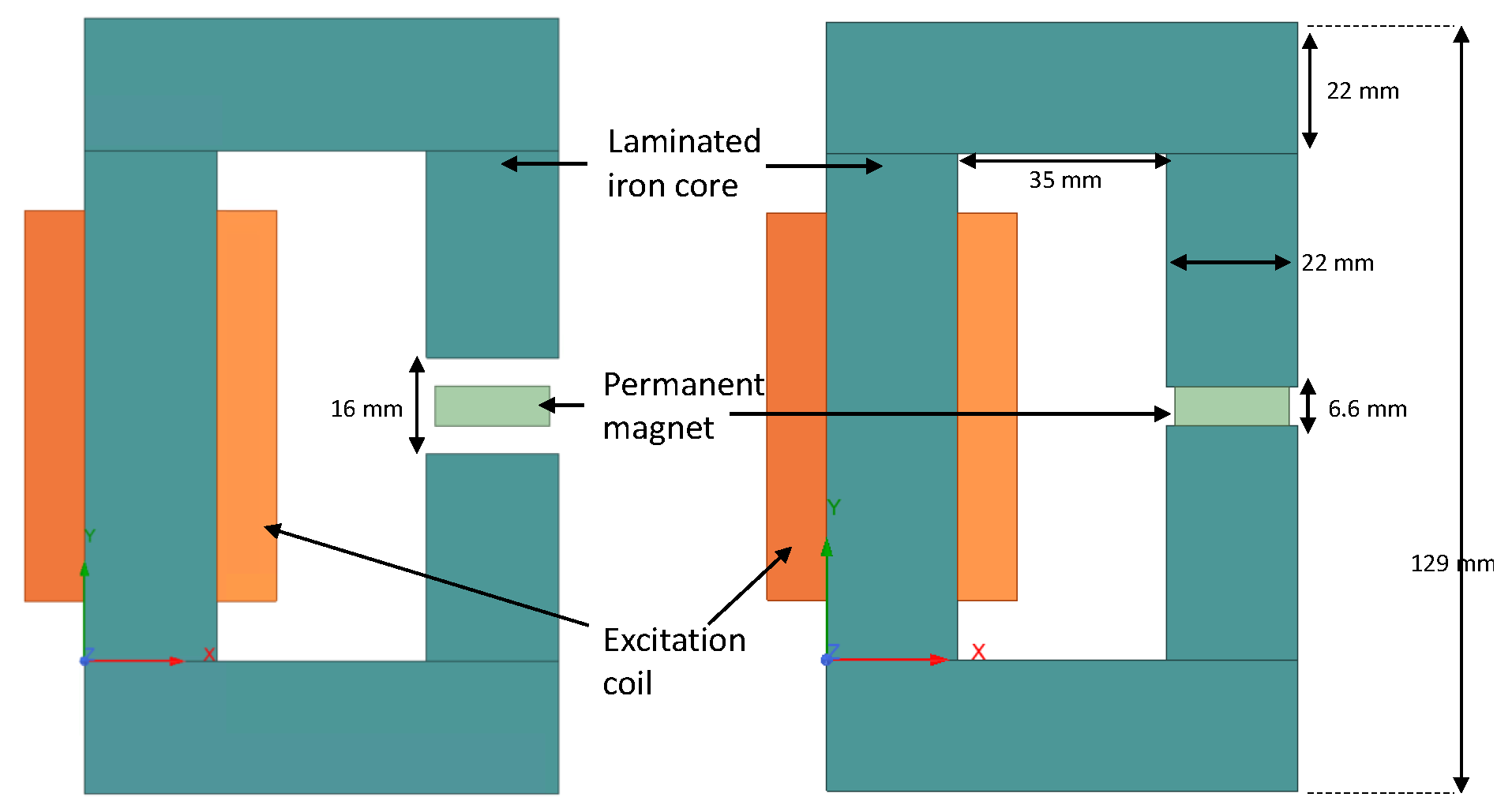
8. Validation and Tests

Although a large number of articles discuss the analysis and modeling techniques of magnet eddy current losses in PMSMs, studies with validation results are limited. The methods of validation used involve both calorimetric and loss segregation from electrical measurements. Calorimetric methods use the following simple relationship between the generated loss ( Q ˙ ), temperature (T) rise of the magnet with time ( d T d t ), magnet mass (m), and the specific heat capacity of magnetic material ( C p ).
Q ˙ = m C p d T d t
Most of the calorimetric experiments are conducted at the component level, using a simple magnetic circuit to create a high-frequency magnetic field across the magnet [32]. In a well-insulated environment, the initial gradient is assumed to be maintained for a measurable time, during which the gradient is determined. This allows us to clearly see the differences in loss generation under a single frequency excitation across segmented and unsegmented magnets [6,60]. Measurement of magnet temperature, while it is attached to the rotor as reported in [30,73], can be subjected to a few challenges such as the accurate prediction of thermal resistance and rotor-specific heat. A different method is followed in [13,74], where the authors use the back-emf reduction due to heated-up magnets as a primary measure. The entire motor is heated up in an oven and the effects on winding resistance are considered to calculate the voltage constant of the motor. The initial temperature rise of magnets is used to calculate the losses.
The magnetic field of the circuit was measured using a coaxial double coil in [58], where the field input is then used to calculate the losses. Similar field measurements in magnetic circuits were used in [75] to validate losses against 3D FEA results. Both static and rotary tests were conducted using a concentrated winding stator in [76]. The loss calculation was done by subtracting other losses from total input electrical power, although this highly depends on the accuracy of other loss models. Similar measurements with power balance and loss segregation calculations are reported in [19,39].

9. Conclusions

This paper summarized selected work on the analysis, reduction strategies, and validation of magnet eddy current losses in PMSMs, aiming to provide motor designers with considerations for rotor design. Strengths and accuracy of magnet loss modeling methods were discussed. A variety of factors affecting magnet losses in a PMSM, such as material properties, rotor shapes, and winding/stator design are summarized, with simple demonstrations using FEA. The most common magnet loss reduction strategy is magnet segmentation, which is dependent on the excitation frequency and magnet dimensions. Validation of the magnet losses in the literature is done using both calorimetric and loss-segregation methods. While the calorimetric method provides direct measurements of losses dissipated as heat losses, the loss segregation method relies upon the accurate estimation of other loss components of the machine. Overall, the magnet sizing and design in PMSMs should consider the inverter switching frequency, spatial harmonics, and rotor/stator topology, as well as PM material characteristics. Detailed PM rotor designs require weighing all these factors to minimize rotor losses and improve motor performance.

Author Contributions

Conceptualization, methodology, investigation, formal analysis, writing—original draft preparation, S.S.; data curation, writing—review and editing, T.B.; visualization, supervision, project administration, K.H. All authors have read and agreed to the published version of the manuscript.

Funding

Grainger Center for Electric Machinery and Electromechanics (Grainger CEME) at University of Illinois at Urbana-Champaign.

Conflicts of Interest

All authors declare that there is no conflict of interest.

References

  1. Huang, W.Y.; Bettayeb, A.; Kaczmarek, R.; Vannier, J.C. Optimization of magnet segmentation for reduction of eddy-current losses in permanent magnet synchronous machine. IEEE Trans. Energy Convers. 2010, 25, 381–387. [Google Scholar] [CrossRef]
  2. Aoyama, Y.; Miyata, K.; Ohashi, K. Simulations and experiments on eddy current in Nd-Fe-B magnet. IEEE Trans. Magn. 2005, 41, 3790–3792. [Google Scholar] [CrossRef]
  3. Ruoho, S.; Dlala, E.; Arkkio, A. Comparison of demagnetization models for finite-element analysis of permanent-magnet synchronous machines. IEEE Trans. Magn. 2007, 43, 3964–3968. [Google Scholar] [CrossRef]
  4. Petrov, I.; Egorov, D.; Link, J.; Stern, R.; Ruoho, S.; Pyrhönen, J. Hysteresis losses in different types of permanent magnets used in PMSMs. IEEE Trans. Ind. Electron. 2016, 64, 2502–2510. [Google Scholar] [CrossRef]
  5. Pyrhönen, J.; Ruoho, S.; Nerg, J.; Paju, M.; Tuominen, S.; Kankaanpää, H.; Stern, R.; Boglietti, A.; Uzhegov, N. Hysteresis losses in sintered NdFeB permanent magnets in rotating electrical machines. IEEE Trans. Ind. Electron. 2014, 62, 857–865. [Google Scholar] [CrossRef]
  6. Yamazaki, K.; Fukushima, Y. Effect of eddy-current loss reduction by magnet segmentation in synchronous motors with concentrated windings. IEEE Trans. Ind. Appl. 2011, 47, 779–788. [Google Scholar] [CrossRef]
  7. Sergeant, P.; Van den Bossche, A. Segmentation of magnets to reduce losses in permanent-magnet synchronous machines. IEEE Trans. Magn. 2008, 44, 4409–4412. [Google Scholar] [CrossRef]
  8. Wang, Y.; Ma, J.; Liu, C.; Lei, G.; Guo, Y.; Zhu, J. Reduction of magnet eddy current loss in PMSM by using partial magnet segment method. IEEE Trans. Magn. 2019, 55, 8105105. [Google Scholar] [CrossRef]
  9. Kim, D.M.; Kim, J.H.; Lee, S.G.; Park, M.R.; Lee, G.H.; Lim, M.S. Estimation Method for Rotor Eddy Current Loss in Ultrahigh-Speed Surface-Mounted Permanent Magnet Synchronous Motor. IEEE Trans. Magn. 2020, 57, 8103205. [Google Scholar] [CrossRef]
  10. Hemeida, A.; Sergeant, P.; Vansompel, H. Comparison of methods for permanent magnet eddy-current loss computations with and without reaction field considerations in axial flux PMSM. IEEE Trans. Magn. 2015, 51, 8107511. [Google Scholar] [CrossRef]
  11. Wu, X.; Wrobel, R.; Mellor, P.H.; Zhang, C. A computationally efficient PM power loss mapping for brushless AC PM machines with surface-mounted PM rotor construction. IEEE Trans. Ind. Electron. 2015, 62, 7391–7401. [Google Scholar] [CrossRef]
  12. Zhang, P.; Sizov, G.Y.; He, J.; Ionel, D.M.; Demerdash, N.A. Calculation of magnet losses in concentrated-winding permanent-magnet synchronous machines using a computationally efficient finite-element method. IEEE Trans. Ind. Appl. 2013, 49, 2524–2532. [Google Scholar] [CrossRef]
  13. Gerlach, T.; Rabenstein, L.; Dietz, A.; Kremser, A.; Gerling, D. Determination of eddy current losses in permanent magnets of SPMSM with concentrated windings: A hybrid loss calculation method and experimental verification. In Proceedings of the 2018 Thirteenth International Conference on Ecological Vehicles and Renewable Energies (EVER), Monte Carlo, Monaco, 10–12 April 2018; pp. 1–8. [Google Scholar]
  14. Atallah, K.; Howe, D.; Mellor, P.H.; Stone, D.A. Rotor loss in permanent-magnet brushless AC machines. IEEE Trans. Ind. Appl. 2000, 36, 1612–1618. [Google Scholar]
  15. Ishak, D.; Zhu, Z.; Howe, D. Eddy-current loss in the rotor magnets of permanent-magnet brushless machines having a fractional number of slots per pole. IEEE Trans. Magn. 2005, 41, 2462–2469. [Google Scholar] [CrossRef]
  16. Toda, H.; Xia, Z.; Wang, J.; Atallah, K.; Howe, D. Rotor eddy-current loss in permanent magnet brushless machines. IEEE Trans. Magn. 2004, 40, 2104–2106. [Google Scholar] [CrossRef]
  17. Ding, X.; Mi, C. Modeling of eddy current loss in the magnets of permanent magnet machines for hybrid and electric vehicle traction applications. In Proceedings of the 2009 IEEE Vehicle Power and Propulsion Conference, Dearborn, MI, USA, 7–10 September 2009; pp. 419–424. [Google Scholar]
  18. Jumayev, S.; Merdzan, M.; Boynov, K.; Paulides, J.; Pyrhönen, J.; Lomonova, E. The effect of PWM on rotor eddy-current losses in high-speed permanent magnet machines. IEEE Trans. Magn. 2015, 51, 8109204. [Google Scholar] [CrossRef]
  19. Balamurali, A.; Lai, C.; Mollaeian, A.; Loukanov, V.; Kar, N.C. Analytical investigation into magnet eddy current losses in interior permanent magnet motor using modified winding function theory accounting for pulsewidth modulation harmonics. IEEE Trans. Magn. 2016, 52, 8106805. [Google Scholar] [CrossRef]
  20. Wu, L.; Zhu, Z.; Staton, D.; Popescu, M.; Hawkins, D. Analytical model for predicting magnet loss of surface-mounted permanent magnet machines accounting for slotting effect and load. IEEE Trans. Magn. 2011, 48, 107–117. [Google Scholar] [CrossRef]
  21. Wu, L.; Zhu, Z.; Staton, D.; Popescu, M.; Hawkins, D. Analytical modeling and analysis of open-circuit magnet loss in surface-mounted permanent-magnet machines. IEEE Trans. Magn. 2011, 48, 1234–1247. [Google Scholar] [CrossRef]
  22. Ede, J.D.; Atallah, K.; Jewell, G.W.; Wang, J.B.; Howe, D. Effect of axial segmentation of permanent magnets on rotor loss in modular permanent-magnet brushless machines. IEEE Trans. Ind. Appl. 2007, 43, 1207–1213. [Google Scholar] [CrossRef]
  23. Wang, J.; Atallah, K.; Chin, R.; Arshad, W.; Lendenmann, H. Rotor eddy-current loss in permanent-magnet brushless AC machines. IEEE Trans. Magn. 2010, 46, 2701–2707. [Google Scholar] [CrossRef]
  24. Bellara, A.; Bali, H.; Belfkira, R.; Amara, Y.; Barakat, G. Analytical prediction of open-circuit eddy-current loss in series double excitation synchronous machines. IEEE Trans. Magn. 2011, 47, 2261–2268. [Google Scholar] [CrossRef]
  25. Wu, L.; Zhu, Z.; Staton, D.; Popescu, M.; Hawkins, D. Analytical model of eddy current loss in windings of permanent-magnet machines accounting for load. IEEE Trans. Magn. 2012, 48, 2138–2151. [Google Scholar] [CrossRef]
  26. Amara, Y.; Reghem, P.; Barakat, G. Analytical prediction of eddy-current loss in armature windings of permanent magnet brushless AC machines. IEEE Trans. Magn. 2010, 46, 3481–3484. [Google Scholar] [CrossRef]
  27. Mukerji, S.K.; George, M.; Ramamurthy, M.; Asaduzzaman, K. Eddy currents in solid rectangular cores. Prog. Electromagn. Res. B 2008, 7, 117–131. [Google Scholar] [CrossRef]
  28. Pyrhonen, J.; Jussila, H.; Alexandrova, Y.; Rafajdus, P.; Nerg, J. Harmonic loss calculation in rotor surface permanent magnets—New analytic approach. IEEE Trans. Magn. 2012, 48, 2358–2366. [Google Scholar] [CrossRef]
  29. Dubas, F.; Espanet, C.; Miraoui, A. Field diffusion equation in high-speed surface mounted permanent magnet motors, parasitic eddy-current losses. In Proceedings of the ELECTROMOTION, Lausanne, Switzerland, 27–29 September 2005; pp. 1–6. [Google Scholar]
  30. Zhu, Z.; Ng, K.; Schofield, N.; Howe, D. Improved analytical modelling of rotor eddy current loss in brushless machines equipped with surface-mounted permanent magnets. IEE Proc.-Electr. Power Appl. 2004, 151, 641–650. [Google Scholar] [CrossRef]
  31. Markovic, M.; Perriard, Y. Analytical solution for rotor eddy-current losses in a slotless permanent-magnet motor: The case of current sheet excitation. IEEE Trans. Magn. 2008, 44, 386–393. [Google Scholar] [CrossRef]
  32. Yamazaki, K.; Shina, M.; Miwa, M.; Hagiwara, J. Investigation of eddy current loss in divided Nd–Fe–B sintered magnets for synchronous motors due to insulation resistance and frequency. IEEE Trans. Magn. 2008, 44, 4269–4272. [Google Scholar] [CrossRef]
  33. de la Barriere, O.; Hlioui, S.; Ahmed, H.B.; Gabsi, M. An analytical model for the computation of no-load eddy-current losses in the rotor of a permanent magnet synchronous machine. IEEE Trans. Magn. 2013, 52, 8103813. [Google Scholar] [CrossRef]
  34. Dubas, F.; Rahideh, A. Two-dimensional analytical permanent-magnet eddy-current loss calculations in slotless PMSM equipped with surface-inset magnets. IEEE Trans. Magn. 2013, 50, 54–73. [Google Scholar] [CrossRef]
  35. Nuscheler, R. Two-dimensional analytical model for eddy-current loss calculation in the magnets and solid rotor yokes of permanent magnet synchronous machines. In Proceedings of the 2008 18th International Conference on Electrical Machines, Vilamoura, Portugal, 6–9 September 2008; pp. 1–6. [Google Scholar]
  36. Deng, F.; Nehl, T.W. Analytical modeling of eddy-current losses caused by pulse-width-modulation switching in permanent-magnet brushless direct-current motors. IEEE Trans. Magn. 1998, 34, 3728–3736. [Google Scholar] [CrossRef]
  37. Chen, L.; Wang, J.; Nair, S.S. An analytical method for predicting 3-D eddy current loss in permanent magnet machines based on generalized image theory. IEEE Trans. Magn. 2015, 52, 8103311. [Google Scholar] [CrossRef]
  38. Nair, S.S.; Wang, J.; Chen, L.; Chin, R.; Manolas, I.; Svechkarenko, D. Prediction of 3-D high-frequency eddy current loss in rotor magnets of SPM machines. IEEE Trans. Magn. 2016, 52, 8107910. [Google Scholar] [CrossRef]
  39. Zhu, Z.; Meng, Z. 3D analysis of eddy current loss in the permanent magnet coupling. Rev. Sci. Instrum. 2016, 87, 074701. [Google Scholar] [CrossRef]
  40. Mirzaei, M.; Binder, A.; Funieru, B.; Susic, M. Analytical calculations of induced eddy currents losses in the magnets of surface mounted PM machines with consideration of circumferential and axial segmentation effects. IEEE Trans. Magn. 2012, 48, 4831–4841. [Google Scholar] [CrossRef]
  41. Sahu, R.; Pellerey, P.; Laskaris, K. Eddy current loss model unifying the effects of reaction field and non-homogeneous 3-D magnetic field. IEEE Trans. Magn. 2020, 56, 7508404. [Google Scholar] [CrossRef]
  42. Rahideh, A.; Korakianitis, T. Analytical calculation of open-circuit magnetic field distribution of slotless brushless PM machines. Int. J. Electr. Power Energy Syst. 2013, 44, 99–114. [Google Scholar] [CrossRef]
  43. Pfister, P.D.; Perriard, Y. Slotless permanent-magnet machines: General analytical magnetic field calculation. IEEE Trans. Magn. 2011, 47, 1739–1752. [Google Scholar] [CrossRef]
  44. Song, Z.; Liu, C.; Chen, Y.; Huang, R. Air-gap Permeance and Reluctance Network Models for Analyzing Vibrational Exciting Force of In-wheel PMSM. IEEE Trans. Veh. Technol. 2022, 71, 7122–7133. [Google Scholar] [CrossRef]
  45. Mukundan, S.; Dhulipati, H.; Tjong, J.; Kar, N.C. Parameter determination of PMSM using coupled electromagnetic and thermal model incorporating current harmonics. IEEE Trans. Magn. 2018, 54, 8110505. [Google Scholar] [CrossRef]
  46. Hemeida, A.; Sergeant, P. Analytical modeling of surface PMSM using a combined solution of Maxwell–s equations and magnetic equivalent circuit. IEEE Trans. Magn. 2014, 50, 7027913. [Google Scholar] [CrossRef]
  47. Tariq, A.R.; Nino-Baron, C.E.; Strangas, E.G. Iron and magnet losses and torque calculation of interior permanent magnet synchronous machines using magnetic equivalent circuit. IEEE Trans. Magn. 2010, 46, 4073–4080. [Google Scholar] [CrossRef]
  48. Abbaszadeh, K.; Alam, F.R. On-load field component separation in surface-mounted permanent-magnet motors using an improved conformal mapping method. IEEE Trans. Magn. 2015, 52, 5200112. [Google Scholar] [CrossRef]
  49. Alam, F.R.; Abbaszadeh, K. Magnetic field analysis in eccentric surface-mounted permanent-magnet motors using an improved conformal mapping method. IEEE Trans. Energy Convers. 2015, 31, 333–344. [Google Scholar] [CrossRef]
  50. Pfister, P.D.; Yin, X.; Fang, Y. Slotted permanent-magnet machines: General analytical model of magnetic fields, torque, eddy currents, and permanent-magnet power losses including the diffusion effect. IEEE Trans. Magn. 2015, 52, 8103013. [Google Scholar] [CrossRef]
  51. Burress, T.; Coomer, C.; Campbell, S.; Seiber, L.; Marlino, L.D.; Staunton, R.; Cunningham, J. Evaluation of the 2007 Toyota Camry Hybrid Synergy Drive System; Technical Report; Oak Ridge National Lab. (ORNL): Oak Ridge, TN, USA, 2008. [Google Scholar]
  52. Zhang, H.; Wallmark, O. Limitations and constraints of eddy-current loss models for interior permanent-magnet motors with fractional-slot concentrated windings. Energies 2017, 10, 379. [Google Scholar] [CrossRef]
  53. Standard Specifications For Permanent Magnet Materials, No. 0100-00. Available online: https://www.datasheetarchive.com/whats_new/ba4f284c073012d3e2490a1b41e0e98c.html (accessed on 31 July 2022).
  54. Yamazaki, K.; Abe, A. Loss investigation of interior permanent-magnet motors considering carrier harmonics and magnet eddy currents. IEEE Trans. Ind. Appl. 2009, 45, 659–665. [Google Scholar] [CrossRef]
  55. Yamazaki, K.; Watari, S. Loss analysis of permanent-magnet motor considering carrier harmonics of PWM inverter using combination of 2-D and 3-D finite-element method. IEEE Trans. Magn. 2005, 41, 1980–1983. [Google Scholar] [CrossRef]
  56. Ou, J.; Liu, Y.; Liang, D.; Doppelbauer, M. Investigation of PM eddy current losses in surface-mounted PM motors caused by PWM. IEEE Trans. Power Electron. 2019, 34, 11253–11263. [Google Scholar] [CrossRef]
  57. Takahashi, N.; Shinagawa, H.; Miyagi, D.; Doi, Y.; Miyata, K. Analysis of eddy current losses of segmented Nd–Fe–B sintered magnets considering contact resistance. IEEE Trans. Magn. 2009, 45, 1234–1237. [Google Scholar] [CrossRef]
  58. Fukuma, A.; Kanazawa, S.; Miyagi, D.; Takahashi, N. Investigation of AC loss of permanent magnet of SPM motor considering hysteresis and eddy-current losses. IEEE Trans. Magn. 2005, 41, 1964–1967. [Google Scholar] [CrossRef]
  59. Yamazaki, K.; Fukushima, Y.; Sato, M. Loss analysis of permanent magnet motors with concentrated windings-variation of magnet eddy current loss due to stator and rotor shapes. In Proceedings of the 2008 IEEE Industry Applications Society Annual Meeting, Edmonton, AB, Canada, 5–9 October 2008; pp. 1–8. [Google Scholar]
  60. Yamazaki, K.; Shina, M.; Kanou, Y.; Miwa, M.; Hagiwara, J. Effect of eddy current loss reduction by segmentation of magnets in synchronous motors: Difference between interior and surface types. IEEE Trans. Magn. 2009, 45, 4756–4759. [Google Scholar] [CrossRef]
  61. Yamazaki, K.; Kitayuguchi, K. Teeth shape optimization of surface and interior permanent-magnet motors with concentrated windings to reduce magnet eddy current losses. In Proceedings of the 2010 International Conference on Electrical Machines and Systems, Incheon, Korea, 10–13 October 2010; pp. 990–995. [Google Scholar]
  62. Choi, G.; Jahns, T.M. Reduction of eddy-current losses in fractional-slot concentrated-winding synchronous PM machines. IEEE Trans. Magn. 2016, 52, 8105904. [Google Scholar] [CrossRef]
  63. Chaithongsuk, S.; Takorabet, N.; Kreuawan, S. Reduction of eddy-current losses in fractional-slot concentrated-winding synchronous PM motors. IEEE Trans. Magn. 2015, 51, 8102204. [Google Scholar] [CrossRef]
  64. Dajaku, G.; Xie, W.; Gerling, D. Reduction of low space harmonics for the fractional slot concentrated windings using a novel stator design. IEEE Trans. Magn. 2013, 50, 8201012. [Google Scholar] [CrossRef]
  65. Wu, L.; Qu, R.; Li, D. Reduction of rotor eddy-current losses for surface PM machines with fractional slot concentrated windings and retaining sleeve. IEEE Trans. Magn. 2014, 50, 8205704. [Google Scholar] [CrossRef]
  66. Reddy, P.B.; El-Refaie, A.M.; Huh, K.K. Effect of number of layers on performance of fractional-slot concentrated-windings interior permanent magnet machines. IEEE Trans. Power Electron. 2014, 30, 2205–2218. [Google Scholar] [CrossRef]
  67. Chaithongsuk, S.; Takorabet, N.; Meibody-Tabar, F. On the use of pulse width modulation method for the elimination of flux density harmonics in the air-gap of surface PM motors. IEEE Trans. Magn. 2009, 45, 1736–1739. [Google Scholar] [CrossRef]
  68. Sato, D.; Itoh, J.i. Total loss comparison of inverter circuit topologies with interior permanent magnet synchronous motor drive system. In Proceedings of the 2013 IEEE ECCE Asia Downunder, Melbourne, VIC, Australia, 3–6 June 2013; pp. 537–543. [Google Scholar]
  69. Korta, P.; Kundu, A.; Balamurali, A.; Iyer, L.V.; Schlager, G.; Kar, N.C. A Novel Hybrid Modelling Approach Towards Comprehensive Drive Cycle Analysis of Si, SiC, and GaN based Electric Motor Drives. In Proceedings of the IECON 2019-45th Annual Conference of the IEEE Industrial Electronics Society, Lisbon, Portugal, 14–17 October 2019; Volume 1, pp. 6331–6336. [Google Scholar]
  70. Kuenzler, M.; Werner, Q.; Schaefer, U. Multidisciplinary Analysis of Permanent Magnet Machines Considering Thermal Contact Resistance. In Proceedings of the 2020 International Conference on Electrical Machines (ICEM), Gothenburg, Sweden, 23–26 August 2020; Volume 1, pp. 940–946. [Google Scholar]
  71. Driesen, J.; Belmans, R.J.; Hameyer, K. Finite-element modeling of thermal contact resistances and insulation layers in electrical machines. IEEE Trans. Ind. Appl. 2001, 37, 15–20. [Google Scholar] [CrossRef]
  72. Joo, D.; Cho, J.H.; Woo, K.; Kim, B.T.; Kim, D.K. Electromagnetic field and thermal linked analysis of interior permanent-magnet synchronous motor for agricultural electric vehicle. IEEE Trans. Magn. 2011, 47, 4242–4245. [Google Scholar] [CrossRef]
  73. Zhao, N.; Zhu, Z.; Liu, W. Rotor eddy current loss calculation and thermal analysis of permanent magnet motor and generator. IEEE Trans. Magn. 2011, 47, 4199–4202. [Google Scholar] [CrossRef]
  74. Malloy, A.C.; Martinez-Botas, R.F.; Lampérth, M. Measurement of magnet losses in a surface mounted permanent magnet synchronous machine. IEEE Trans. Energy Convers. 2014, 30, 323–330. [Google Scholar] [CrossRef]
  75. Fratila, R.; Benabou, A.; Tounzi, A.; Mipo, J.C. A combined experimental and finite element analysis method for the estimation of eddy-current loss in NdFeB magnets. Sensors 2014, 14, 8505–8512. [Google Scholar] [CrossRef] [PubMed]
  76. Liu, D.; Jassal, A.; Polinder, H.; Ferreira, J. Validation of eddy current loss models for permanent magnet machines with fractional-slot concentrated windings. In Proceedings of the 2013 International Electric Machines & Drives Conference, Chicago, IL, USA, 12–15 May 2013; pp. 678–685. [Google Scholar]
Figure 1. (a) Theoretical BH curve of a PM; (b) measured recoil curves of a NdFeB sample at 120 °C [3]; (c) measured minor hysteresis loops in a magnet at room temperature [4].
Energies 15 06116 g001
Figure 2. Sources of eddy currents and their paths.
Energies 15 06116 g002
Figure 3. Two-dimensional FEA models: gapped core (left) and ungapped core (right) to analyze magnet losses.
Energies 15 06116 g003
Figure 4. Comparison of loss vs. frequency between analytical models.
Energies 15 06116 g004
Figure 5. Comparison of loss vs. frequency between analytical and FEA models.
Energies 15 06116 g005
Figure 6. Magnet eddy current losses vs. frequency for sintered NdFeB classes (same isotropic relative permeability of 1.05 assumed).
Energies 15 06116 g006
Figure 7. Magnet eddy current losses vs. frequency for bonded NdFeB classes (same conductivity of 0.01 MS/m assumed).
Energies 15 06116 g007
Figure 8. Magnet eddy current losses vs. frequency for a few selected magnet types.
Energies 15 06116 g008
Figure 9. Magnet eddy current losses vs. frequency for different circumferential segmentation.
Energies 15 06116 g009
Figure 10. Eddy current paths associated with different harmonics at 300 A and β = 60 [59].
Energies 15 06116 g010
Figure 11. Magnet eddy current loss vs. segmentation for an example slot and carrier harmonic [60].
Energies 15 06116 g011
Table 1. Common magnet types and their properties [53].
Material μ r σ (MS/m) B r (T)
NdFeB Bonded (BN10)1.260.010.7
Alnico 51.521.0
Sm-Co1.11.160.8–1.15
NdFeB Sintered1.050.661–1.5
Publisher’s Note: MDPI stays neutral with regard to jurisdictional claims in published maps and institutional affiliations.

