1. Introduction
Recently, sensors have played an effective role in supporting the world’s tendency toward artificial intelligence (AI). To operate these sensors, they need either external power or batteries that, in many cases, are inefficient for a huge number of sensors in a limited place because of the complexity and maintenance of wire connections. In addition, it is difficult to replace the batteries in underground pipeline networks [
1], the human body, and complex machinery [
2], to name a few. Energy harvesters have become an effective alternative technique for energizing the sensor network. Various energy harvesters have been developed to harness ambient energy such as mechanical vibration into electrical energy in the range of tens of milli-Watts. Piezoelectric and electromagnetic energy harvesters are commonly used to exploit ambient vibrations to produce electrical power to operate self-powered wireless sensor networks (WSN) [
3].
The piezoelectric energy harvesting (PEH) mechanism utilizes the conversion property of piezoelectric material. This property allows the mechanical strain to convert into electrical charges and, hence, electrical power [
3]. The mechanical strain can be produced by stress applied to the surface of piezoelectric material in the form of mechanical vibrations. PZT layers or batches are commonly laminated to the surfaces of a cantilever to extract the transverse vibration energy from the surrounding.
In its basic structure, the electromagnetic energy harvester (EEH) commonly comprises an oscillating magnet over a coil. The relative motion between the magnet and the coil causes a change in magnetic flux, producing an induced current in the coil. The generated electromotive force (emf) measured in voltage follows Faraday’s law of induction, in which the emf is the rate of change of the magnetic flux. Niell G. [
4] experimentally validated a basic electromagnetic energy harvester that consists of a magnet suspended by a spring over an induction coil. The harvester was excited from the base. The normalized power density was measured at a rate of 1.7 µW/(m/s
2)
2/cm
3 at a resonance frequency of 112.25 Hz. Huicong Liu [
5] presented the design, modeling, and optimization of a hand-shaking electromagnetic energy harvester. The harvester was tested at different tube lengths and winding coil widths. The experimental tests of an optimized design of the harvester produced a maximum power of 568.66 μW at the hand-shaking acceleration of 1 g and frequency of 6.7 Hz.
In addition to maximizing the harvester’s output power and efficiency, researchers recently focused on broadening the bandwidth frequency of vibrations to constant output power instead of a peak output at a resonance frequency. One way to do that, for example, is by using hybrid energy harvesters (HEH), in which a couple of harvesters are integrated into one device. Each harvester is designed to optimally capture energy at a specific narrow range of frequencies. The total output power of HEH will then span over a wider spectrum of frequencies. Rajarathinam [
6] proposed a hybrid harvester that is made of a cantilever PZT beam with a magnet oscillator attached to its free end. The frequency bandwidth of the hybrid harvester generates power in a broad bandwidth compared to standalone PEH or EEH harvesters (i.e., 2.99 Hz vs. 1.17 Hz). Toyabur [
7] designed, modelled, and experimentally tested a 4-DOF vibration-based hybrid harvester. The harvester operates over a bandwidth frequency of 12 Hz to 22 Hz. It was found that at 16 Hz, the harvester produced a maximum power of 244 µW.
Xia Li [
8] and Muthalif [
9] recently suggested piezoelectric and electromagnetic hybrid energy harvesters with a magnet oscillator embedded in a bluff body. The primary concept of the proposed hybrid harvesters is to utilize the bluff body as an extra room to integrate or embed extra energy harvesters. It was found that the output power of the hybrid harvester in ref. [
8] outperformed the power of the standalone PZT harvester by 121% at the same optimal resistive load and geometrical dimensions. However, attaching an EM harvester with its coil inside the bluff body may load the harvester making it difficult to vibrate. Both harvesters are operated by flow-induced vibrations, namely, galloping and vortex-induced vibration (VIV). VIV is introduced due to alternating near-wall vortex shedding or wakes over a curved bluff body surface. VIVs represent a structure–fluid interaction that leads the cantilever beam to oscillate transversally [
10]. In general, when the bluff body is developed with sharp edges rather than being curved (i.e., cylindrical), it will vibrate by galloping phenomena [
11].
In addition to the multi-DOF hybrid technique mentioned above, there exist other techniques to increase the bandwidth that are, for example, tunable energy harvesting, impact-based energy harvesting, and bistable energy harvesting techniques [
12,
13]. The tunable energy harvesters can be either manual or self-tuning [
13]. An example of a manual tunable vibration energy harvester is the one proposed by Wu [
14]. The experimental setup of this harvester design consists of piezoelectric elements and fixed and movable parts of a proof mass. The idea behind this type of harvester is to adjust the center gravity of the mass by a movable screw. Accordingly, the operating frequency of the system will be changed. Challa [
15] proposed another example of a tunable harvester based on vibrating a cantilever beam between attractive and repulsive magnetic forces. In their prototype, the resonance frequency is tunable in the range of 22–32 Hz.
A vibro-impact system is another way of widening the broadband frequency of the harvester. This technique utilizes a mechanical stopper or limiter that alters the mechanical stiffness of the vibrating element of the harvester upon impact. The amplitude spectrum becomes nonlinear with a wider bandwidth [
12]. Hassen [
16] proposed an impact oscillator with an electromagnetic cantilever harvester. The cantilever beam is placed between upper and lower impact oscillators. The oscillators resonant upon impact. A pick-up coil, attached at the free end of the cantilever, vibrates across two permanent magnets. The simulated results of the harvested power demonstrated an extended bandwidth of 16–36 Hz at an output power of 4 μW.
The bistable or multi-stable energy harvester is classified as a nonlinear harvester. It experiences more than one stable equilibrium position under a nonlinear restoring force that results in complex potential energy [
12]. In comparison to the linear energy harvester, the bistable energy harvester can generate more power at low frequencies and higher bandwidth [
17]. Erturk and Inman [
18] compared the power generation of a liner energy harvester and a bistable energy harvester. Over a frequency range of 5–8 Hz and input rms acceleration of 0.35 g, the generated average power by a bistable harvester is greater than that of a linear harvester. For a 14.5-cm-long cantilever, an average power output of 8.45 mW was generated.
Despite all the attempts mentioned above to increase the output power and the bandwidth, there exist limited studies that investigate exploiting the inside room of the bluff body to integrate sub-systems of harvesters. In this research work, we propose a new configuration of a hybrid energy harvester that utilizes the bluff body room to embed electromagnetic energy harvesters. This paper is organized as follows: the next section is devoted to presenting the detailed conceptual design of the harvester. The electromechanical dynamic modeling of the harvester using Lagrange’s formulation is then outlined. The electromechanical and electromagnetic formulation of the coupling coefficients is also introduced. Parametric analysis is conducted afterwards to investigate the effect of the design parameters on the overall performance of the harvester. The key design parameters are identified to maximize the output power and bandwidth.
3. Dynamic Modeling
In this work, the lumped mass approach is adopted to model the coupled dynamics of the harvester. In principle, this method discretizes the harvester into a finite number of degrees of freedom to reduce computational complexity. The proposed hybrid energy harvester will be modeled based on the following assumptions:
The first mode (fundamental mode) of the beam is dominant;
The harvester materials are isotropic;
The composite beam is modeled as an Euler–Bernoulli beam;
The rotation and rotary inertia of the bluff body are negligible.
It is also assumed that the geometrics of the PZT layer are identical to the substrate. PZT-5A material properties are assumed in this research. PZT-5A is not sensitive to temperature variations, so its performance remains constant in contrast to PZT-5H.
Figure 3 show the equivalent model for the hybrid energy harvester. It consists of two main sub-systems that are the PEH and the EEH. These systems are combined to form a two-degree of freedom (2-DoF) VIV-based hybrid harvester. The PEH sub-system consists of an equivalent parameter of a mass (
), a stiffness (
), a damping (
), and an external resistive load (
). On the other hand, the equivalent EEH sub-system consists of a permanent magnet mass (
), a stiffness (
), a damping (
), and an external load (
). The electromechanical coupling coefficient (
) of PEH and the electromagnetic coupling coefficient (
) of EEH are introduced in the model to characterize the coupling of energy transfer between the mechanical and electrical domains.
and
express the displacements of both the equivalent mass of PEH (
) and the oscillating magnetic mass (
), respectively. The vortex-induced vibrations force (
) is exerted on the bluff body due to the wind flow. This force causes the system to vibrate in the
-direction perpendicular to the wind flow (
). The following sub-sections discuss the derivation of all these equivalent parameters in detail.
3.1. Equivalent Lumped-Mass Parameters of the Harvester
In this section, the equivalent masses, stiffnesses, and damping of the harvester are derived.
is the lumped equivalent mass of the composite substrate beam, including the PZT layer and the cylindrical bluff body attached to the free end of the cantilever beam. This equivalent mass also accounts for the mass of the electromagnetic (EM) coil inside the bluff body. Following the assumption of one mode, the equivalent mass
can be expressed using the following equation [
19]:
where
,
and
are the masses of PZT layer, substrate beam, bluff body, the EM coil, and the fluid added mass, respectively.
,
, and
can be calculated physically using the density–volume relationship (i.e.,
). The fluid added mass (
) can be evaluated using [
10]:
where
is the added mass coefficient [
10] and
is the air density (1.20 kg/m
3).
and
are the cylindrical buff body’s length and outer diameter, respectively. The oscillating magnet is denoted by
. Additionally, the coil mass is represented by
which can be estimated from the coil geometry and shape.
The stiffness of the composite beam (
) can be estimated using the structural mechanic principles. Hook’s law that relates the tip deflection of the beam to the applied tip force leads to the equivalent stiffness of the beam being [
19]:
where
is the equivalent flexural rigidity of the composite beam [
20].
is the beam length. It is worth noting that, in this research, the PZT layer is assumed to have the same length as the substrate. The oscillating magnet, on the other hand, is attached inside the bluff body using a regular spring with stiffness of (
).
If the fluid added damping is negligible, the structural damping coefficients of the piezoelectric layer () and the electromagnetic () sub-systems harvesters can be calculated by the damping–mass–stiffness relationship () where is the damping coefficient of the material.
3.2. Electromechanical Model of a PZT Layer
When mechanical stress is applied to the surface of the piezoelectric material, the total electrical charge (
) generated across a piezoelectric layer thickness is expressed as [
21]
where
and
are the electromechanical coupling coefficient and the piezoelectric capacitance, respectively.
is the open-circuit voltage across the piezoelectric layer. The electromechanical coupling coefficient (
) and the piezoelectric capacitance (
) are calculated using [
22]:
in which
and
are the piezoelectric constant and the electric permittivity of PZT material, respectively.
is the width and
is the thickness of the PZT layer. One can note that the coupling coefficient and the piezoelectric capacitance depend on the geometrical parameters of the harvester and the material properties.
3.3. Electromagnetic Coil Design and Model
As proposed, the electromagnetic energy harvester (EEH) consists of a permanent magnet (PM) oscillating inside a multi-layer coil. In this section, the electromagnetic coil design and model are presented. The EEH is placed inside the bluff body, which, in turn, is attached to the free end of the composite beam. The EEH multi-layer cylindrical coil location inside the bluff body (denoted by
and
) and its dimensions (i.e.,
and
) are illustrated in
Figure 4.
3.3.1. Coil Effective Inductance and Resistance
Coil inductance and resistance are two critical parameters that need to be designed optimally. Wheeler’s spiral formula [
23] is used to estimate the coil inductance. The formula assumes a square cross-sectional area of the coil (i.e.,
), as shown in
Figure 4b. The coil inductance (
) in Henry is provided by
where
is the number of turns of the coil. The coil resistance (
) in ohms can be calculated as [
24]:
where
is the copper wire resistivity (i.e., 1.68 × 10
−8 Ωm [
25]) and
is the coil wire diameter.
3.3.2. The Electromagnetic Coupling Coefficient
The electromagnetic coupling coefficient establishes the link between the energy transfer from the mechanical domain to an electrical domain. In EEH, when a permanent magnet is oscillating inside a multi-layer coil, an electromotive force (
) is generated. This force represents the voltage across the coil that can be calculated using Faraday’s law, which implies [
26]:
where
is the fill factor that measures the ratio between the volume of the coil wires and the volume that encloses the wires or windings. In our analysis, the fill factor is assumed to be 0.33.
is the average magnetic flux inside the coil. The flux is a function of the relative magnet position (
) inside the coil. So, the electromotive force can be expressed as
where
is the electromagnetic coupling coefficient as a function of the relative position of the magnet to the coil. Following the derivation procedure presented by ref. [
27], the coupling factor is represented by
where
and
is the coil cross-section area and is equal to
.
and
are the residual magnetic flux density and the volume of the magnet, respectively. Equation (11) is a compact form of the EM coupling coefficient developed by our research work. The accuracy of this formula is tested by comparing it with the numerical double integration form of the coefficient provided in ref. [
27]. Using the coil geometrical and material properties presented in [
27],
Figure 5 show the coupling coefficient (
) as a function of the relative position (
) of the magnet inside a coil using both Equation (11) and the double integration formula. It is clearly shown that Equation (11) is a closed form of the coupling coefficient with an exact matching with the double integration method. The coupling coefficient is maximum when the magnet is at the top or bottom surfaces of the coil. The coupling is zero at the center of the coil. As such, the magnet should be placed near the top or bottom surfaces of the coil to harvest more power. The mechanical power is introduced to the harvester structure via the vortex-induced vibration of the wind that is discussed next.
3.4. Vortex-Induced Vibrations (VIV) Force
Due to the interaction between the airflow and the free-moving cylindrical bluff body, vortex-induced vibration is initiated to oscillate the bluff body. When the frequency of the shedding wake is close to the fundamental natural frequency of the structure, lock-in or synchronization phenomenon occurs. This phenomenon increases the power and the bandwidth of the harvester. In this research, the force that describes the vortex-induced vibrations is modified by introducing a sinusoidal force. However, for a more accurate and comprehensive model, the Van Der Pol-wake oscillator, for example, can be incorporated into the dynamic model to capture the interaction between the structure of the harvester and the wake passing over the bluff body [
10]. This allows investigating the effect of the lock-in region on expanding the resonance. However, this research focuses more on maximizing the power and widening the bandwidth outside the lock-in region by manipulating the geometrical parameters and materials properties of the harvester. As a result, the vortex-induced vibration (VIV) force generated by the steady laminar flow of wind is assumed in its simplest sinusoidal form. In general, the lift force dominates the VIV force, and it can be expressed by [
10]:
where
is the air density,
is the wind stream velocity,
is the projected area of the cylindrical bluff body (i.e.,
), and
is the lift coefficient (assumed 0.60).
is the vortex shedding frequency (Hz) of the wake that depends on the wind stream velocity and the outer diameter of the bluff body (
) as follows [
10]:
is the Strouhal number which represents a dimensionless ratio of inertial forces of the flow acceleration to the inertial forces of the convective acceleration. Strouhal number is a function of Reynold’s number that determines the flow regimes [
28]. It has been reported that the quality of the vortex is degraded beyond Reynold’s number of 4000 [
29]. As a result, this reduces the harvested power from the flow. The diameter of the harvester should be selected optimally to keep Reynold’s number below 4000.
number is between 0.2 and 0.3 for a cylindrical body [
30]. For our analysis,
is assumed to be 0.2.
3.5. Equations of Motion Using Lagrange’s Formulation
In this section, the coupled equations of motion (EOM) based on an equivalent lumped mass model of the harvester are derived thoroughly using Lagrange’s formulation which is an entirely scalar technique that describes the system in terms of its kinetic and potential energies. It represents the system’s kinetic energy (
), potential energy (
), and the work in terms of generalized coordinates, and it states that:
are the generalized coordinates of the system. is the dissipation energy. are the generalized forces. In our proposed design and the lumped-mass model of the hybrid harvester, there are four degrees of freedom which are represented by the following generalized coordinates:
Additionally, the generalized forces of the system are then,
.
The kinetic energy of the harvester is the sum of the mechanical and electrical field energies. As such, the kinetic energy is [
27]:
The last term in Equation (17) represents the coupling of kinetic energy between the mechanical and electrical domains in the electromagnetic coil. As indicated previously, the electromagnetic coupling coefficient () is also a function of the relative position of the magnet inside a coil. However, for small oscillations about the equilibrium point, the coupling coefficient can be assumed constant.
The total potential energy of both the mechanical and electrical domains of the harvester can be expressed as [
21]
The last term in Equation (18) is another coupling term between the mechanical and electrical domains of the harvester due to the piezoelectric material characteristics. The total mechanical and electrical dissipation energy in the harvester is provided by
is the external electrical resistive load of the PEH and
is the external load of EEH. Now, substituting Equations (17)–(19) into the formulation of Lagrange, Equation (16), the equations of motion of the harvester are:
The equations of motion are coupled via the electromechanical and electromagnetic coefficients. It will be shown later in
Section 4 that both coefficients have optimum values to maximize the output power of the harvester. The next section explores the analytical and numerical solutions of the EOM.
4. Analytical and Numerical Solutions of EOM
The equations of motion can be solved analytically and numerically at the given assumptions. MATLAB
® ode45 solver has been utilized to numerically solve the coupled nonlinear equations of the motion at assumed zero initial conditions [
31]. The EOM is solved for the generalized coordinates of the model. The total root-mean-square (RMS) output power (
) of the harvester is, in general, the summation of the output power of PEH and EEH that is
where
and
are the RMS electrical output power of PEH and EEH, respectively. Assuming a sinusoidal output power, both electrical powers are calculated at a steady-state condition from the following equations
The maximum electrical currents (
and
) at the steady state of the PEH and EEH are evaluated numerically. For instance, the PEH current (
) is directly calculated from Equation (23). The efficiency (
) of the harvester is determined by [
32]:
If a constant electromagnetic coupling coefficient (i.e.,
) is assumed, the numerical solution of the EOM can be validated by solving them analytically. For numerical solution, the EOM can be represented in a state-space form by setting the following states,
=
,
=
,
=
,
=
,
=
,
=
, and
=
. Consequently, the state space representation in a matrix form is then
The state–space equations can be solved numerically using ode45 in MATLAB
®. For the analytical solution of the EOM, it is assumed that the solution of each generalized coordinated at a steady-state response is provided by
where
and
are the amplitudes of the steady-state response of each parameter. For a stable system, the response to a sinusoidal VIV force is asymptotically sinusoidal with the same vortex shedding frequency (
in rad/s) of the flow. The magnitude and phase of each response are then determined by a transfer function between the input force and the output associated variables in Equation (29). To obtain the transfer functions of the system, the Laplace transform is first applied to the EOM (Equations (20)–(23)). Then, by defining the following transfer functions,
where
represents the magnitude of the VIV force and the EOM is represented in a complex form that results in
Equation (31) is algebraically solved for the four predefined transfer functions in Equation (30). Finally, using Equation (30), the steady-state amplitudes and are determined. It is worth noting that the amplitudes are, in general, complex numbers that define the amplitude and the phase of each variable.
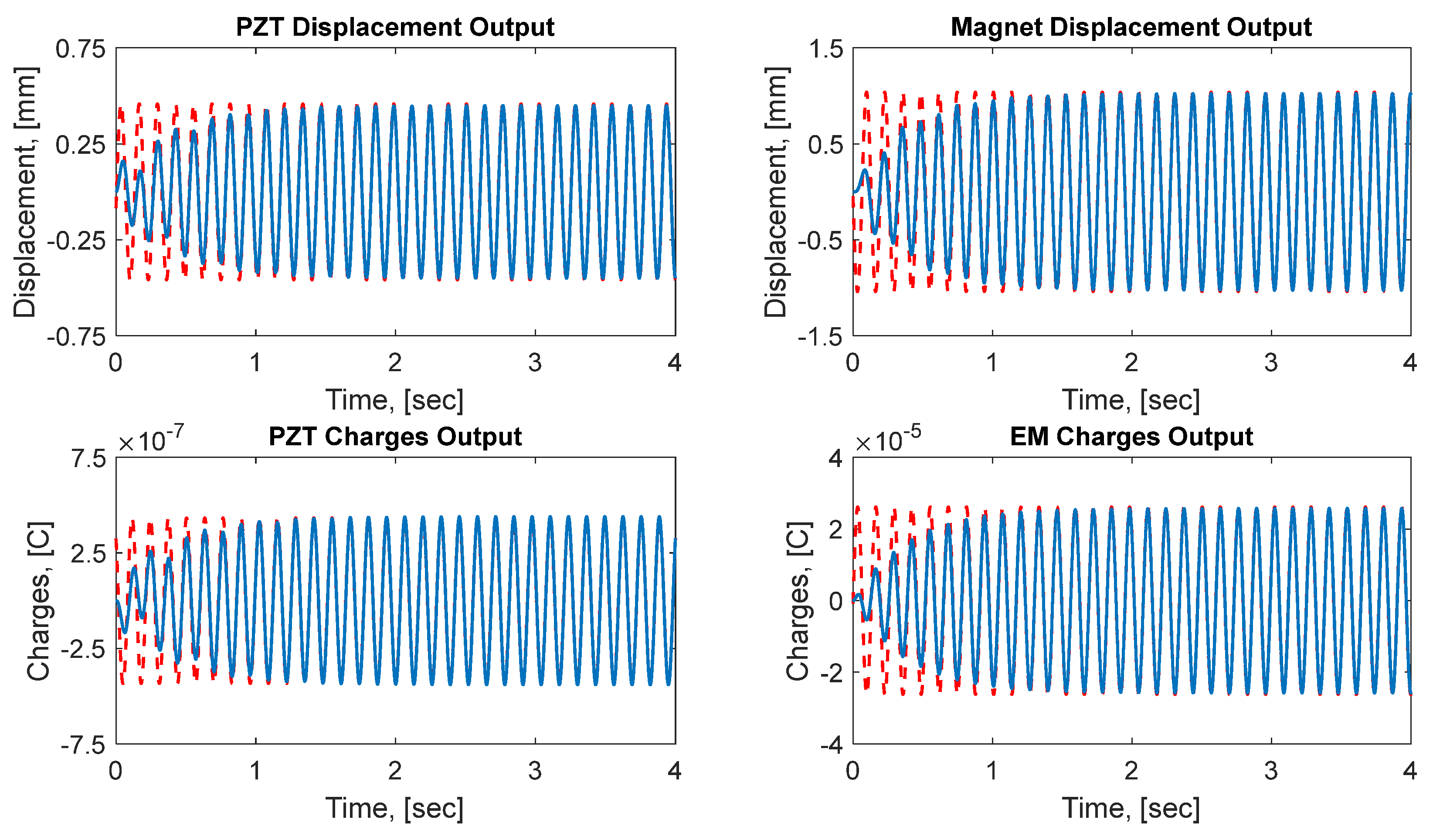
The analytical and numerical solutions are validated using the harvester parameters provided in
Table 1. The magnitude of the VIV force (
) is set to 0.0148 N.
Figure 6 show the analytical and numerical solutions of the EOM for the four generalized coordinates of the harvester. The results clearly show an exact agreement between the numerical approach and the
steady-state analytical method provided by Equation (31). As a result, this validates both approaches to solving the EOM of the harvester. A detailed parametric analysis is presented in the next section. The analysis is conducted to explore the effect of critical design parameters on the overall performance of the harvester in terms of output power and bandwidth.
5. Parametric Analysis of Design Variables
In this section, a parametric study or analysis of the harvester key design parameters is introduced. This study investigates the influence of the mechanical, electromechanical, and electromagnetic parameters on the overall harvester performance. The design parameters are perturbed to explore their effects in improving harvester power and bandwidth. The effect of the model parameters, including masses, springs, damping, coupling coefficients, external loads, and coil number of turns on the overall performance of the harvesters, is discussed in subsequent subsections. Each parameter is varied within a range of studies to examine its effect on the harvester rms power and bandwidth. For this analysis, physical geometric and material properties listed in
Table 1 are assumed. It should be noted that using
Table 1 data, the second fundamental of the harvester is around a wind speed of 2 m/s. This study also assumes a maximum operating wind speed of 10 m/s.
5.1. The Effect of Masses
Figure 7 show the RMS power of the hybrid energy harvester (HEH) as a function of the wind speed (
) at different composite beam masses (
). The harvester is mechanically considered a two-degree-of-freedom system. As such, two resonance frequencies at each given mass of the beam are observed. The power is harvested closer to the second fundamental frequency. A similar experimental observation was reported in the hybrid system tested in ref. [
6]. The increase of the harvested power at the second fundamental frequency is attributed to the increased contribution of the piezoelectric energy harvester at that frequency or wind speed. The electromagnetic harvester produces less power due to the relative motion between the oscillating magnet and the coil attached to the bluff body.
It is clearly shown that the maximum power and bandwidth increase as the mass decreases. The power is increased by almost 15 times when decreases from 0.04 kg to 0.01 kg. This decrease in mass leads to an increase in the two fundamental frequencies of the harvester ( and ). In general, this is an expected result as the fundamental frequencies are inversely proportional to the mass of the beam. However, the shift is more significant in the second natural frequency. As the frequencies increase, the wind speed needed to excite the harvester resonances increases as described by Equation (15) (i.e., ). However, at higher wind speed, the fluid added mass increases on the bluff body.
The output power versus the magnet mass (
) is depicted in
Figure 8. The power is maximum at an optimum magnet mass of around 0.02 kg. This amount of mass shifts the fundamental frequency of the harvester to be closer to a wind speed of 2 m/s. The power and bandwidth sensitivity to the change in
mass is smaller than that of
mass. From the above discussion, smaller masses of the harvester should be maintained to increase the harvesting power and bandwidth. If a narrow wind speed range can be sustained, then the second natural frequency can be optimized to be located inside that range of speeds.
The effect of permanent magnet (PM) mass (
) on both the maximum and average rms power is illustrated in
Figure 9. It shows that the PM mass (
) has an optimal value at which the power of the proposed harvester is maximum. The average power is calculated over a range of 0 m/s to 10 m/s wind speed. The harvester’s maximum power gradually increases and reaches around 19 mW when the EM mass is 8.75 g. The average power varies from 1.26 mW down to 1.13 mW (−10% from the maximum) over a wide range of PM mass. This indicates that the average power is insensitive to the PM mass as it becomes larger. It should be noted that a larger mass indicates a larger volume of a magnet, which is crucial to increasing the harvesting of electromagnetic power. This is clearly indicated by Equation (12), which determines the electromagnetic coupling coefficient (
). As such, the composite beam and PM masses should be carefully designed and optimized to maximize the harvester-generated power and bandwidth.
5.2. The Effect of Stiffness
The structural stiffness of the composite beam and the oscillating magnet spring are important model parameters that affect the overall harvesting performance.
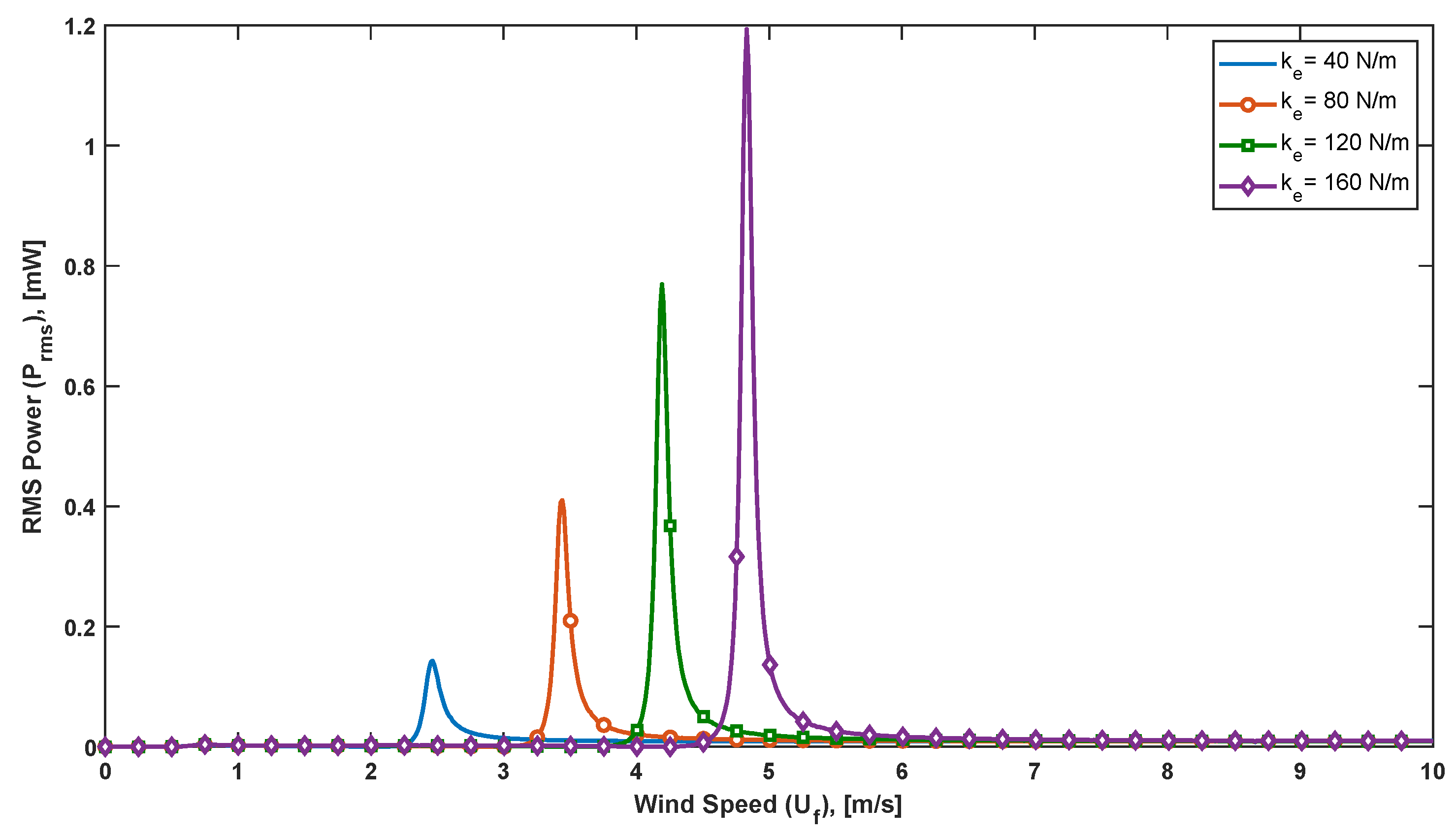
Figure 10 and
Figure 11 show the output total power of the harvester over a range of wind speeds at different stiffness (
and
) values of both beam and PM magnet spring, respectively. In both cases, as the stiffness increases, the total power increases. The power at the second natural frequency is always dominant. The effect of increasing magnet spring stiffness (
) on enhancing the harvested power is comparably equal to that of the composite beam stiffness (
). In both cases, the average increase in the power per 1 N/m change is around 0.02 mW. However, the effect of both stiffnesses on the harvester bandwidth is not significant.
5.3. The Effect of Coupling Coefficients
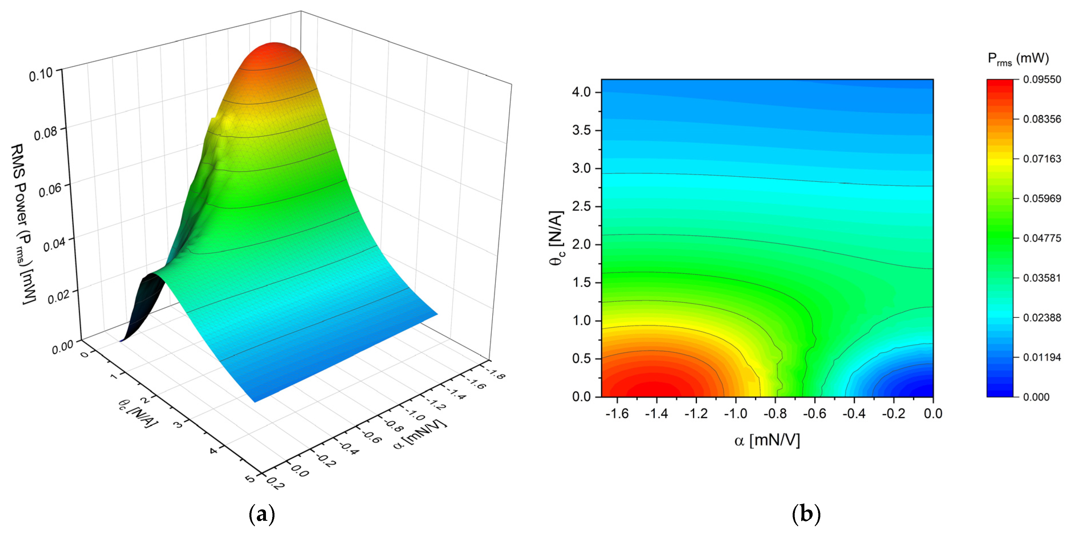
Piezoelectric and electromagnetic coupling coefficients are the link between the mechanical and electrical domains in the hybrid harvester. The amount of energy transferred from one domain to another is determined by those two coefficients. Their values play an important role in improving the harvester’s performance. Both coefficients are governed by the geometric and material properties of the harvester (see Equations (5) and (12)). Therefore, designing the masses or the stiffnesses of the harvester will eventually affect the coupling coefficients.
Figure 12 show the rms power of a hybrid harvester as a function of both coupling coefficients. It is clearly shown that the power is maximum at a combination of optimal coupling coefficients. However, optimal coupling coefficients require altering other harvester model parameters as they are all linked to the basic geometrical properties of the harvester.
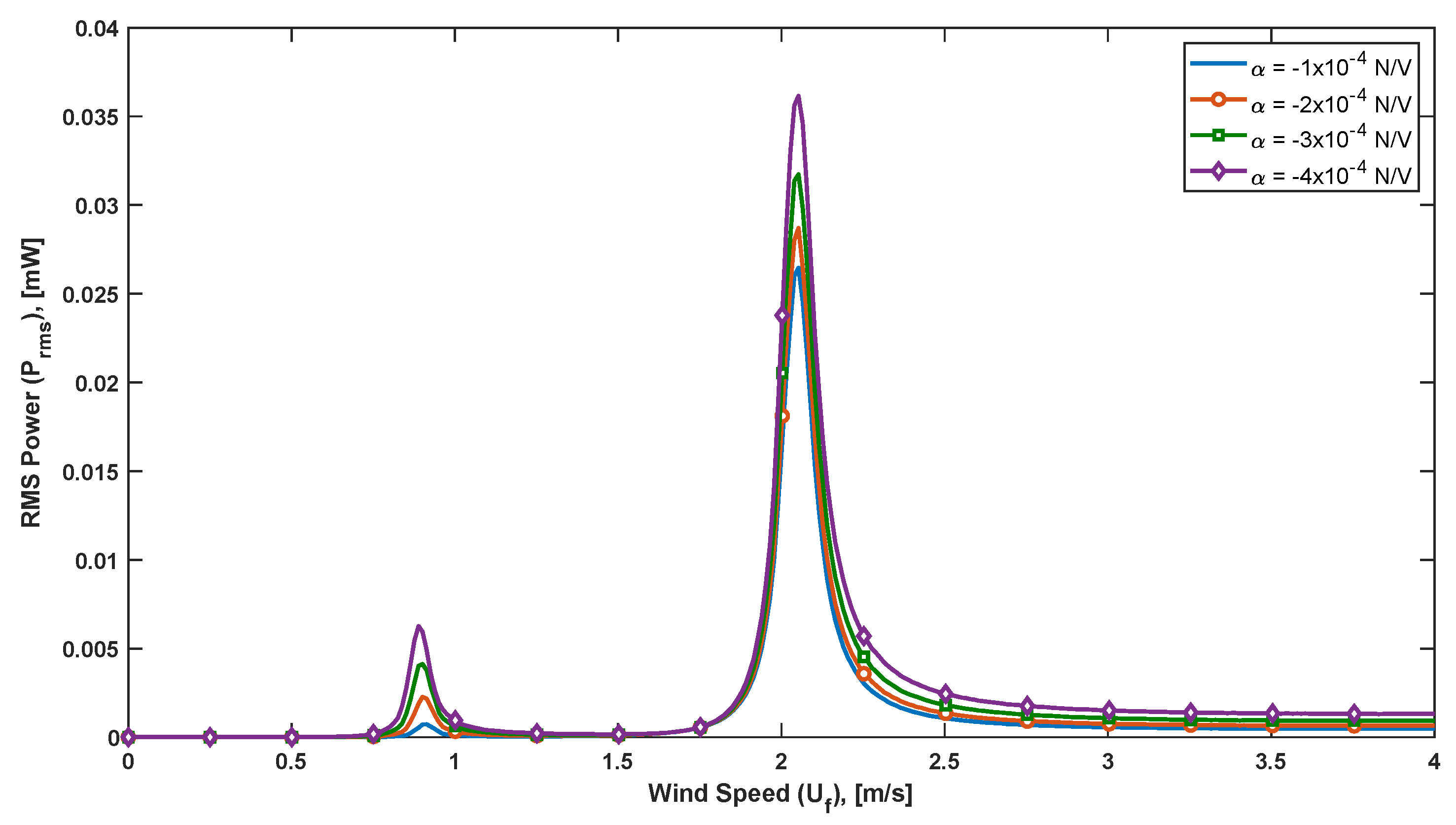
The effect of the piezoelectric coupling coefficient (
) on the total output power is shown in
Figure 13. It can be concluded that the power increases with increasing the coupling coefficient as expected. However, the increase is minor if the change in the coefficient is small (i.e., low sensitivity to
).
Figure 14 demonstrate the output power versus the wind speed at various electromagnetic (EM) coupling coefficients (
). As the coupling coefficient increases, the harvested power at the first natural frequency of the harvester is almost unaltered. However, the EM coupling coefficient slightly alters the second natural frequency of the harvester. The power at the second natural frequency decreases as the coupling coefficient increases. The reason behind this inversely proportional relationship is that, at low coil inductance, the EM coupling coefficient is treated as an added damping term in the mechanical side of the harvester. For instance, assume a negligible coil inductance (i.e.,
), substitute
from Equation (22) in (21), the effective damping term of the EM harvester becomes (
). This clearly illustrates the reason behind the decrease of the output power at a high EM coupling coefficient.
Although the power decreases as the coupling coefficient is increasing, the power is, in fact, increasing beyond the second fundamental frequency. For instance, at a coupling factor (
) of 1 N/A, the harvested power beyond the second natural frequency increases slightly as the wind speed increases. In contrast, at a higher coupling factor of 5 N/A, the increase in the harvested power is much larger than that of a low coupling coefficient (i.e., it is five times larger at a wind speed of 8 m/s). This increase in harvesting power beyond the second natural frequency (at higher wind speed) has been reported by many researchers [
33]. It is associated with the nature of the electromagnetic circuit of the harvester provided by Equation (22), in which the inductive impedance dominates at higher frequencies or wind speeds. One more advantage of increasing the EM coupling coefficient is the increase in the bandwidth of the harvester. At a fixed power output of 0.3 mW, the bandwidth of a harvester with a larger coupling coefficient is almost 2.5 times larger than that of the case with lower coupling.
5.4. The Effect of External Loads
Piezoelectric and electromagnetic external loads (
and
) represent an equivalent electrical circuit to be operated by the harvester. It is assumed that the circuits are purely resistive loads. Other forms of external loads have been studied by other researchers, such as a combination of resistance and inductive impedance loads [
34]. In electrical circuits, impedance matching [
35] is a key success in maximizing the power transfer from the harvester to the electrical loads.
Figure 15 show the output power versus the PZT loads at different wind speeds. It can be clearly seen that there is always an optimal resistive PZT load at which the output power is maximum. Using the parameters shown in
Table 1, the harvester has a second natural frequency at a wind speed of 2 m/s. This is the reason that the power at speed close to 2 m/s is more than other speeds under this analysis. In contrast, the external electromagnetic load (
) has no significant effect on the output power, as depicted in
Figure 16. The reason is that the multi-layer coil resistance (
) dissipates more power before it is harvested.
5.5. The Effect of Number of Turns of the Coil
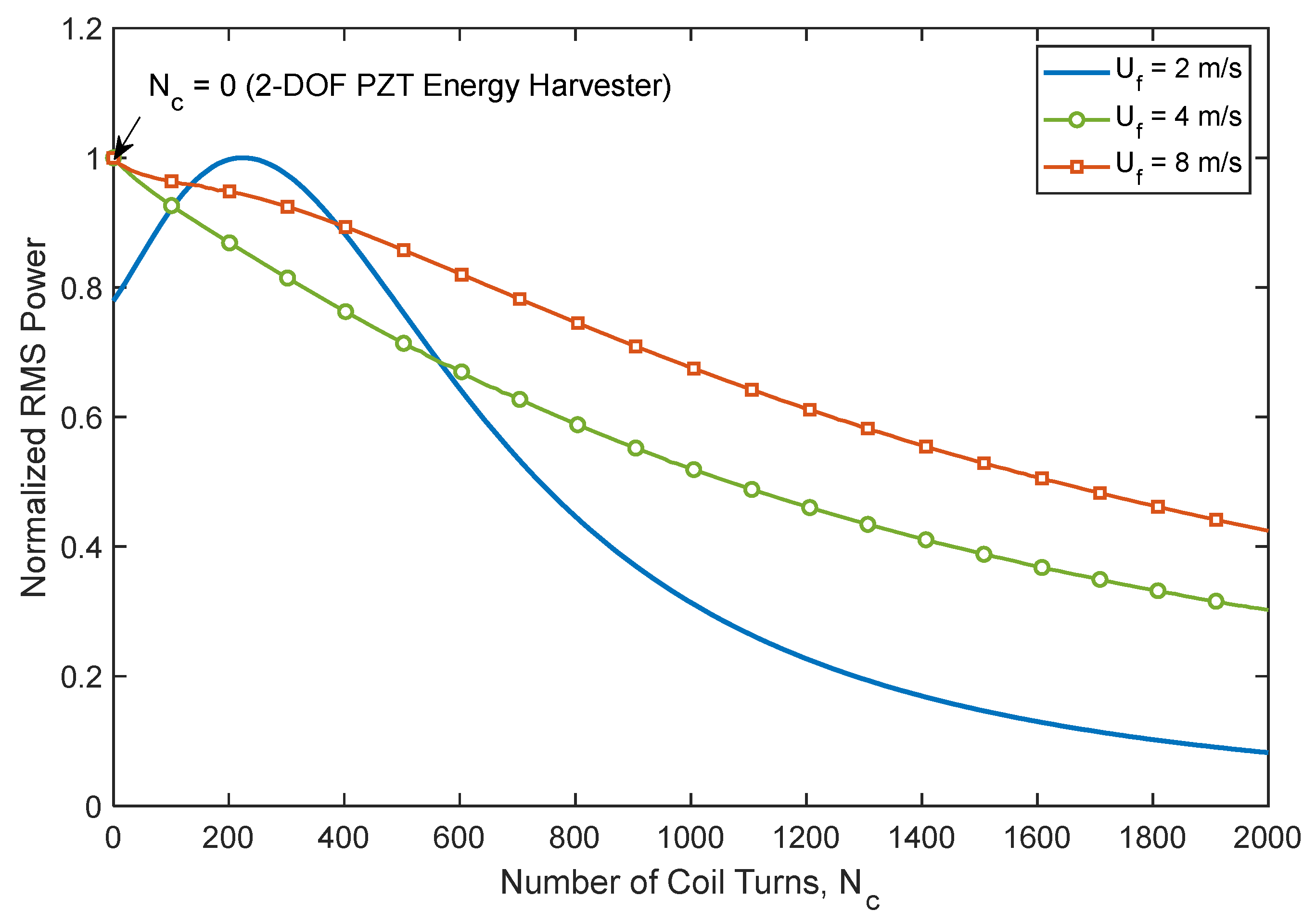
This section investigates the effectiveness of embedding a multi-layer coil into a bluff body of the harvester. The coil mass loads the bluff body making the harvester difficult to oscillate and, hence, generate power. Therefore, in this analysis, two designs of the hybrid harvester are investigated. The first design is the original hybrid harvester proposed in the previous sections with a coil inside a bluff body. The other design variation is the same hybrid harvester but without a coil. In both designs, an oscillating permanent magnet is attached inside the bluff body. It is worth noting that when the number of turns is zero (i.e., no coil), this case represents only a 2DOF standalone piezoelectric energy harvester (2DOF PEH).
The comparison is conducted between the two suggested designs: with and without the coil, using the parameters listed in
Table 1. The harvested rms power is calculated at a different number of turns of the coil, as depicted in
Figure 17. The power is normalized with respect to the maximum output rms power at each case of wind speed. Close observation reveals that the harvester without a coil (2DOF PEH) generally outperforms the hybrid energy harvester (HEH) at a wide range of wind speeds. The power decreases as the number of turns increases as expected, except at a wind speed close to the second fundamental frequency of the harvester, that is, in this case, 2.0 m/s. At this speed, an optimum number of turns is noted at
. This might be attributed to the large oscillations at resonance that overcome the coil’s weight. The steady-state time history of the PZT and magnet masses at a wind speed of 2 m/s at the optimum number of turns is plotted in
Figure 18. At 2 m/s, the hybrid harvester resonates at its second fundamental frequency at which the masses are vibrating out-of-phase. This type of motion replicates the working principle of the Tuned Mass Damper (TMD) [
36], in which a mass–spring–damper oscillator is attached to a structure to reduce its excessive vibrations. In HEH or 2DOF PEH, the permanent magnet and the spring act as a TMD.
To illustrate this, the vortex-induced vibrations due to the wind flow excite the HEH structure to vibrate, and, hence, the wind energy is transferred first to PEH. Part of the energy absorbed by the PEH is then transferred to the EEH as a TMD. The EEH power is harvested by the inertia force and EM damping acting on the magnet. In a wind speed range between 0 to 10 m/s, the parametric study conducted in this section concludes that most of the modeling parameters have optimal values at which the harvester power is maximum. In addition, for HEH, it is suggested to place the coil outside the bluff body to reduce the loading on the PZT composite beam to improve the overall performance of the harvester. To this end, with a proper design procedure, the PEH and EEH can be designed optimally to maximize the harvester wind energy.


