Review

Battery Energy Storage for Photovoltaic Application in South Africa: A Review

by
Bonginkosi A. Thango
* and
Pitshou N. Bokoro
Department of Electrical and Electronic Engineering Technology, University of Johannesburg, Johannesburg 2028, South Africa
*
Author to whom correspondence should be addressed.
Energies 2022, 15(16), 5962; https://doi.org/10.3390/en15165962
Submission received: 12 July 2022 / Revised: 5 August 2022 / Accepted: 14 August 2022 / Published: 17 August 2022
(This article belongs to the Special Issue Electrical Power Engineering and Renewable Energy Technologies)

Abstract

:
Despite the significant slowdown of economic activity in South Africa by virtue of the COVID-19 outbreak, load shedding or scheduled power outages remained at a high level. The trend of rising load-shedding hours has persisted throughout most of the year 2022. Operational issues within the South African power utility inflamed the unpredictable nature of generation capacity, resulting in unscheduled outages at several generating units, mostly due to multiple breakdowns. To forestall substantial spikes in energy costs, an increasing number of enterprises and homeowners have started to gradually adopt renewable energy technologies to sustain their operational demand. Therefore, there is an increase in the exploration and investment of battery energy storage systems (BESS) to exploit South Africa’s high solar photovoltaic (PV) energy and help alleviate production losses related to load-shedding-induced downtime. As a result, the current work presents a comprehensive and consequential review conducted on the BESS specifically for solar PV application and in the South African context. The research investigations carried out on BESS for PV application are crucially examined, drawing attention to their capacities, shortcomings, constraints, and prospects for advancement. This investigation probed several areas of interest where the BESS-PV scheme is adopted, viz., choice of battery technology, mitigating miscellaneous power quality problems, optimal power system control, peak load shaving, South African BESS market and status of some Real BESS-PV projects. The techno-economic case scenario has been proposed in the current research and results yield that lithium-ion batteries are more viable than Lead–acid batteries.

1. Introduction

The aging power plant infrastructure of the South African national electric utility, coupled with unscheduled blackouts, have hampered the power producer’s generating capacity for years, and these bottlenecks continue to be a major hurdle to future expansion. The utility issues, which include a congested electric grid, an outdated, unreliable, and inadequately maintained generating fleet, and a yearning for new generation capacity, have been accentuated by the increasing load-shedding days since 2018, as shown in Figure 1 [1]. Until significant supplemental wattage capacity is invested, their vulnerability to load shedding will be incessant. Increasing levies by national power utilities and municipalities, in addition to load shedding, have augmented the investment case for industries in renewable energy generation and power efficiency initiatives [2,3]. To circumvent hefty increases in electricity costs, an influx of major corporations is considering implementing alternative energy sources to support their daily operations. PV grid-tied systems are playing a central role in this shift in the South African energy sector on account of their environmental merits and attenuated carbon emissions [4,5]. Since the enactment of the Integrated Resource Plan (IRP), in March 2011, by the Department of Energy (DoE), there has been a gradual increase in the deployment of solar PV. The IRP 2019 steers the energy sector, with a transition from coal power generation, increasing the adoption of renewables and thereby reducing South African dependence on coal. The IRP advocates for 7958 MW of solar PV to be generated by end of 2030 [6,7].
This load shedding concurs with South Africa’s power utility decaying Energy Availability Factor (EAF), which estimates the performance of electricity-generating stations in accordance with the electrical energy they supply to the national grid. In 2021, 2020 and 2019, the EAF was estimated at about 61.8%, 65% and 66.9%, respectively. The EAF had come down rapidly since 2018, which was estimated at about 71.9%, just below the power utility’s 74% target. In 2021, a low of about 53.3% was reported on a weekly average EAF. Figure 2 demonstrates interest or progress in terms of renewable energy in South Africa in the context of installed generation capacity. The planned capacity by 2030 is expected to contribute about 10.5% of South Africa’s generation capacity [6,7].
It can be observed that coal generation is yet the main electrical power source, responsible for approximately 81.4% of the power fed to the grid, succeeded by renewable energy sources, viz., solar and wind—responsible for approximately 6.7%. The increase in the deployment of renewable energies will aid in curbing not only the emission of greenhouse gases but also the dependency on coal generation and reduction in load shedding. Commercial activities will be able to continue their operations with investments in BESS-PV scheme.
Although solar PV is proliferating, it also poses operational challenges attributable to its unpredictability and investment cost. Subsequently, solar PV exhibits variations inherent to renewable energy. These variations can emerge at any interval from seconds to minutes, necessitating the deployment of supplemental energy management devices. PV systems are additionally confronted by the cost differential during peak hours and the power quality given to the power grid. As a result, energy storage technologies are integral parts that can support PV systems to be able to provide energy for longer hours in the absence of sunlight.
In the literature [8], energy storage systems have been suggested as a mechanism to feasibly alleviate faults [8]. These issues are connected to energy penetration levels and can equip solar PV with highly desired adaptability and robustness [9,10]. Solar PV storage systems, in this regard, endorse power management, such as load levelling or peak demand reduction, for power balancing and quality upgrades [11]. Consequently, these systems provide on-site load flow control, allowing for power storage during low-demand times to be utilized during peak hours [12]. As a result, South Africans can lower rates associated with electricity consumption while also enhancing the quality of the power grid [13].
The fundamental issue with solar energy is the availability of sunlight, which does not correlate to the demand. This is particularly troublesome for residential or business users, who are frequently prohibited from returning surplus PV power to the grid that is generated when there is a plethora of individual load demand. Solar PV-battery systems permit these customers to store surplus energy for later usage, as demonstrated in Figure 3, thereby enhancing their solar energy consumption [14].
A summary of recent related research works is tabulated in Table 1 to outline the contribution that can be made by the current study and the main focus thereof.
This work has been organized as follows:
A brief account of solar PV and battery energy storage system technologies with their crucial information is covered in Section 2. Research on battery storage systems applications is comprehensively detailed with supporting arguments and opposing arguments in Section 3. Current status and some real PV-battery projects are discussed briefly in Section 4. A simulation case scenario with a techno-economic analysis of two different BESS-PV systems is performed to assess the economic performance in Section 5. Feasible future courses and suggestions for the research on BESS-PV systems are also presented. This review research is generally concluded in Section 6 by describing the importance of the findings.

2. Solar PV and Battery Energy Storage System

The rooftop solar PV systems convert solar radiation into electrical energy that may be consumed by South African residents, as shown in Figure 4 [20]. Any power that is not utilized is fed into the main grid. To conserve energy generated throughout the day, large-scale batteries can be coupled to solar PV systems. When the system is not producing enough power, particularly at night or in adverse weather conditions, this energy may be consumed. Using the power generated by a solar PV system throughout the day alleviates the amount of power purchased from the grid, lowering the energy costs.

2.1. Selection and Deploying a Solar PV-Battery System

A variety of factors will significantly affect which solar PV-battery system is ideal for a household, including:
  • Amount of power and time of consumption;
  • Dimensions of available rooftop space;
  • Positioning and direction of solar PV panels.
Understanding the amount of energy consumption in a household may facilitate the evaluation of the impact of a solar PV system on the energy costs and establish whether battery storage is a cost-effective option. To realize the best options, licensed solar installers certified by South African PV GreenCard may further be consulted.

2.2. Emplacement of the Solar PV-Battery System

When solar PV panels are oriented directly toward effective solar irradiation between 09:00 a.m. and 15:00 p.m., they achieve the greatest power generation:
  • The PV panels must not be exposed to any shade. Even if a single PV cell is obscured by objects such as branches, roof vents, or satellite dishes, many other PV cells will lose power. Due to variations in the flow of energy through the panel, the latter will have a significant influence on the output of the panel.
  • The efficacy of batteries can be affected by the temperature in the surrounding environment.
  • Batteries necessitate a setting or housing that is well-insulated and well-ventilated. A battery enclosure should ideally be placed on the south or west side of a South African building.

2.3. Connecting Solar PV-Battery System to the Power Grid

Under its jurisdiction to administer electricity tariffs in South Africa, the National Energy Regulator of South Africa (NERSA) approved the establishment of a Renewable Energy Feed-in Tariff (REFIT) for the country. The feed-in tariff obligates the Renewable Energy Purchasing Agency (REPA), to purchase renewable energy from eligible producers at preset rates [21,22].

3. Battery Technologies

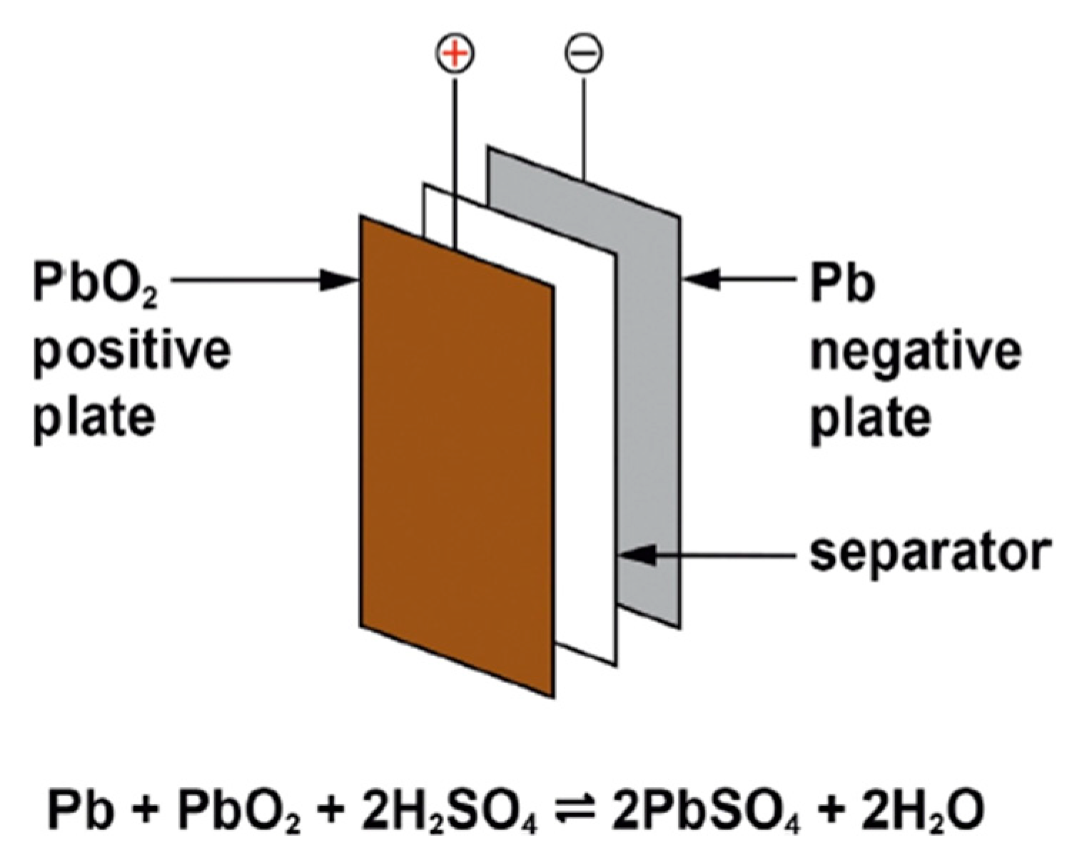
3.1. Lead–Acid Battery

The lead–acid battery, created in 1859, is the first kind of rechargeable battery ever developed [23]. Lead–acid batteries have a suboptimal energy density when compared to contemporary rechargeable batteries.
Lead–acid cells are composed of lead alloy grids (solid electrodes) that operate as current collectors and mechanically support the positive and negative active elements. The grids are interlaced with a permeable, electrically isolator and arrayed as positive and negative plates. The plate stack is embedded into an adequately contoured polymer housing to embody the cell elements and the electrolyte with the coupled positive and negative plates, terminals, a lid and venting arrangements. The construction of a lead–acid battery is shown in Figure 5.
The operating voltage of the lead–acid cell is reasonably high at approximately 2.05 V. The positive active material (PAM) is considerably permeable lead dioxide (PbO₂) and the negative active material (NAM) is delicately isolated lead. The electrolyte utilized in the discharge process is thinned liquefied sulfuric acid (HSO4). HSO4 ions move to the negative electrode during discharge, producing H+ ions and lead sulfate (SO₄²). Lead dioxide reacts with the electrolyte at the positive electrode to yield lead sulfate particles and water (H2O), as shown in Figure 6. Both electrodes are discharged to a feeble conductor, lead sulfate (PbSO4), and the electrolyte is incrementally diluted as the discharge progresses. On charging, the reactions are reversible [24,25].
The most recent innovations [26,27] have used enhanced lead batteries in a variety of grid-related plans as well as smaller-scale industrial and domestic energy storage applications. In recent years, systems with integrated super-capacitors have been described in addition to conventional lead–acid batteries; they are commonly referred to as carbon-enhanced (LC) lead batteries. These could have a negative electrode made of a mix of lead–acid and supercapacitor negatives made of carbon. The positive electrode is exactly like the one in a typical lead–acid battery in every way. The current tendency in operating renewable energy sources, especially solar PV sources, is for periodic discharges rather than a continuous restoration of the battery to a full state of charge (SOC). This partial state-of-charge (PSoC) behavior can be detrimental to lead–acid batteries since it induces permanent corrosion of the negative electrode, and sustainable development strategies are still being investigated [28,29].

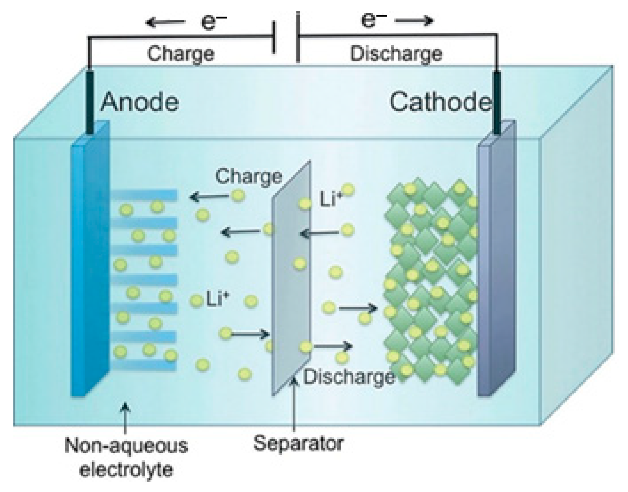
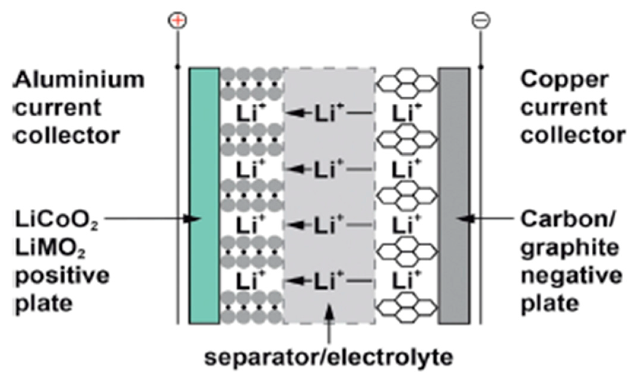
3.2. Lithium-Ion Battery

Lithium-ion (Li-ion) batteries store energy in positive electrode materials composed of lithium extracts adequate for reversible physical adsorption of Li-ions and negative electrode materials made of carbon and can properly support Li in the solid state [30]. Since Li interacts severely with water, non-aqueous electrolytes are employed [31]. These are ionizable organic diluents, such as propylene carbonate, in solution with adequate lithium salts. To improve the safety of the cells, the separators are microporous plastic strips that may be covered with ceramic particles, as shown in Figure 7.
Li-ion cells must be meticulously assessed in terms of safety. They have a high energy density and a volatile organic electrolyte.

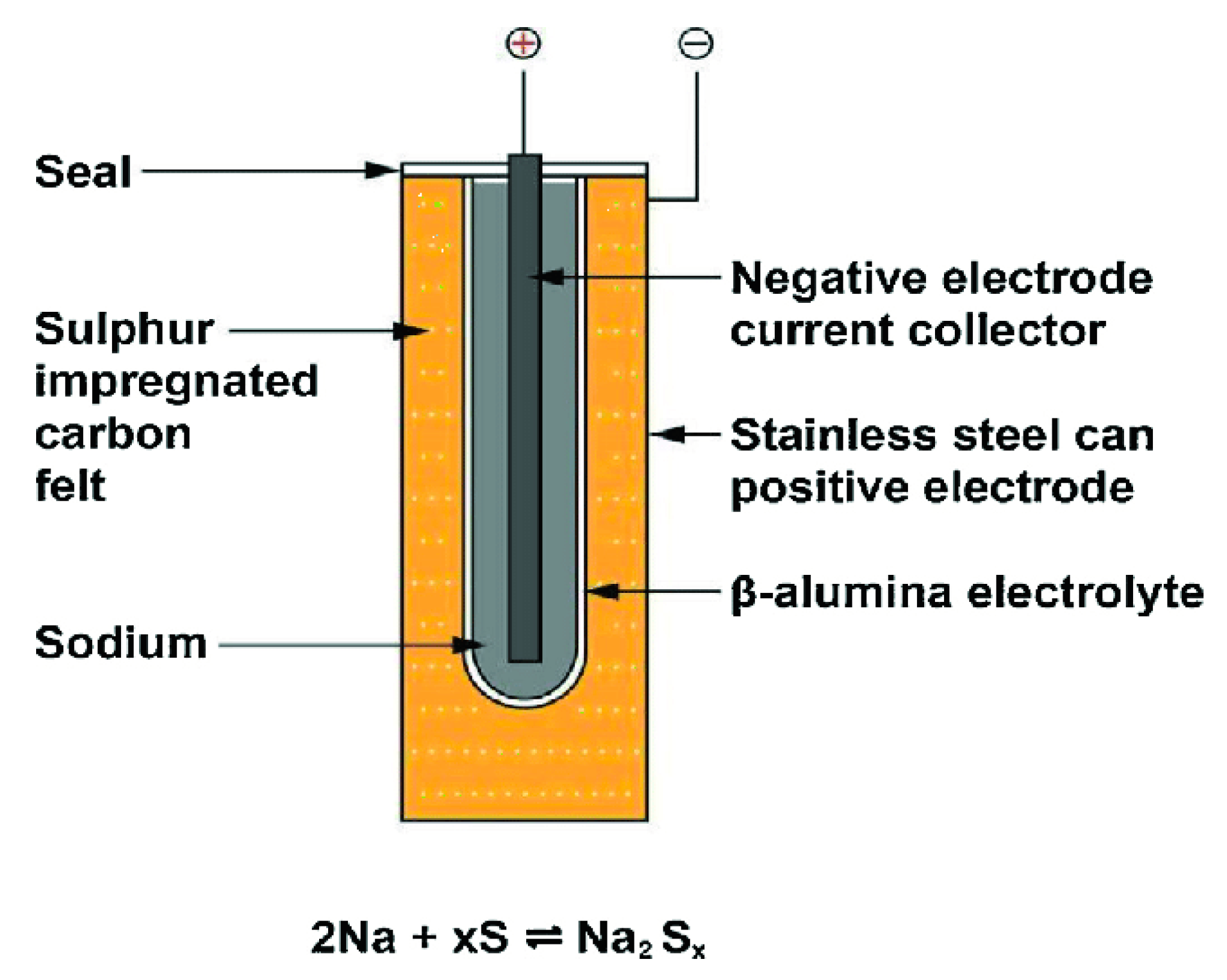
3.3. Sodium–Sulfur Battery

The anodes of sodium–sulfur (Na-S) batteries are viscous liquid sodium and sulfur, and they run at hot temperatures, around 300 and 350 °C, to maintain the electrode’s liquid and to provide strong ionic conductivity in the electrolyte, which is a ceramic material [32,33]. At processing temperature, the electrolyte is beta-alumina (b-Al2O3), which transmits sodium ions. When sodium and sulfur are released, sodium polysulfide is produced [34]. They have a far superior energy density and durability over lead–acid batteries. To preclude cell defects from proliferating, security is essential, and careful design is essential. The chemistry and principal components of a sodium–sulfur battery are shown in Figure 8.
Although Na-S batteries are made from abundant and inexpensive raw items, the production processes, as well as the necessity for insulation, cooling, and temperature control, make them fairly pricey. They are more cost-effective in large units since the thermal management of smaller batteries contributes to the cost relative to the battery’s volume. As a consequence, they are primarily employed for utility load levelling in big substations.

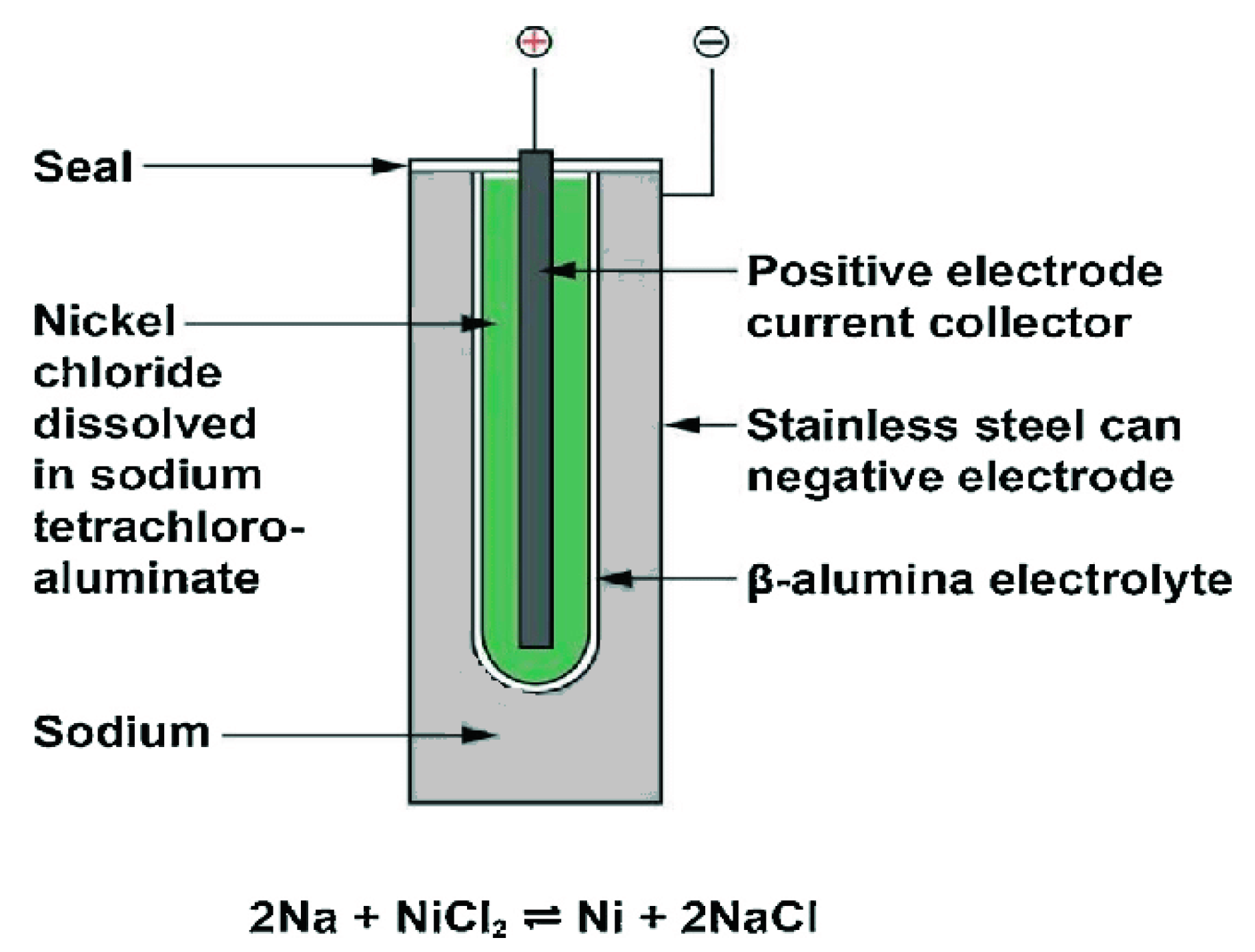
3.4. Sodium–Nickel Chloride Battery
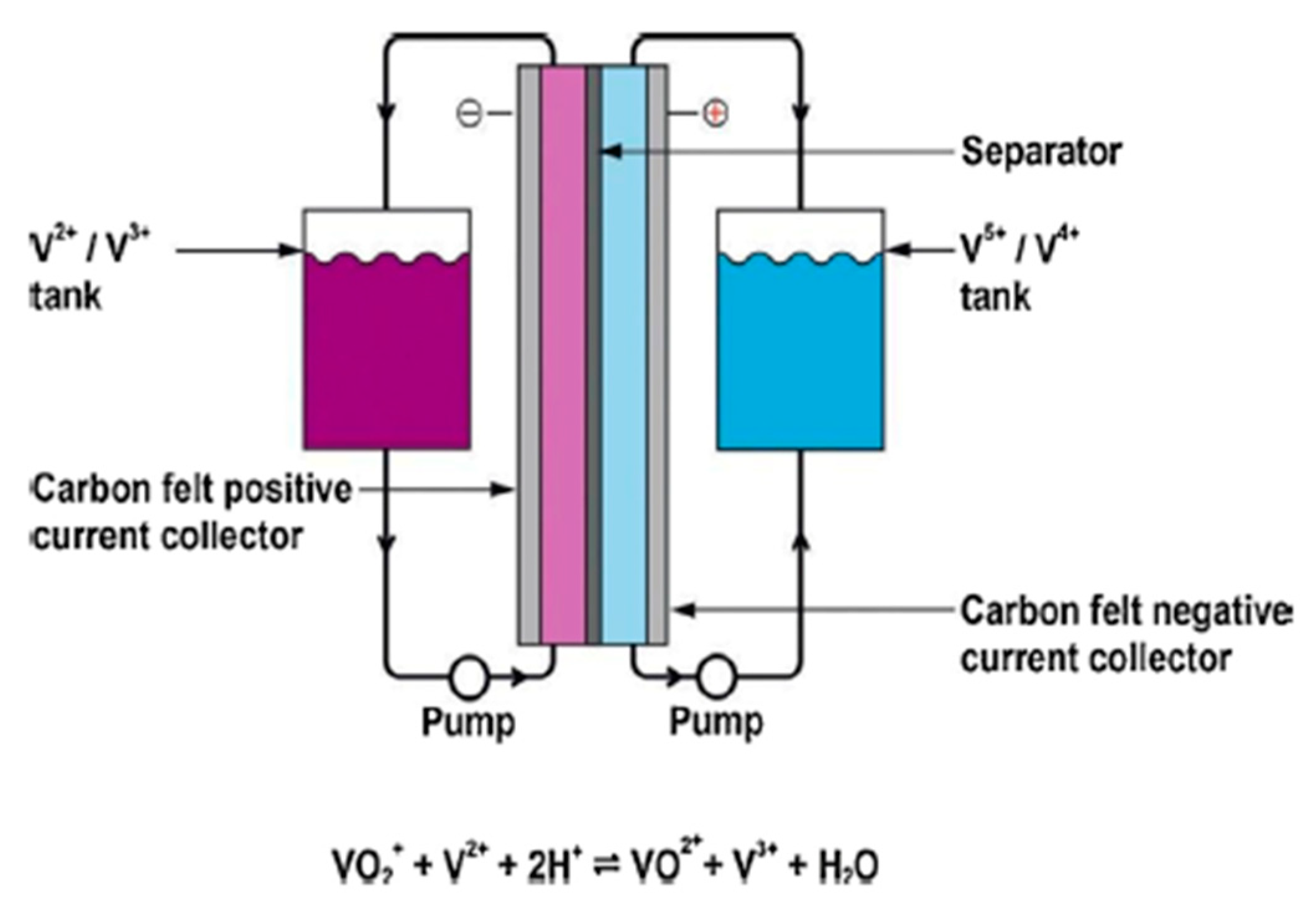
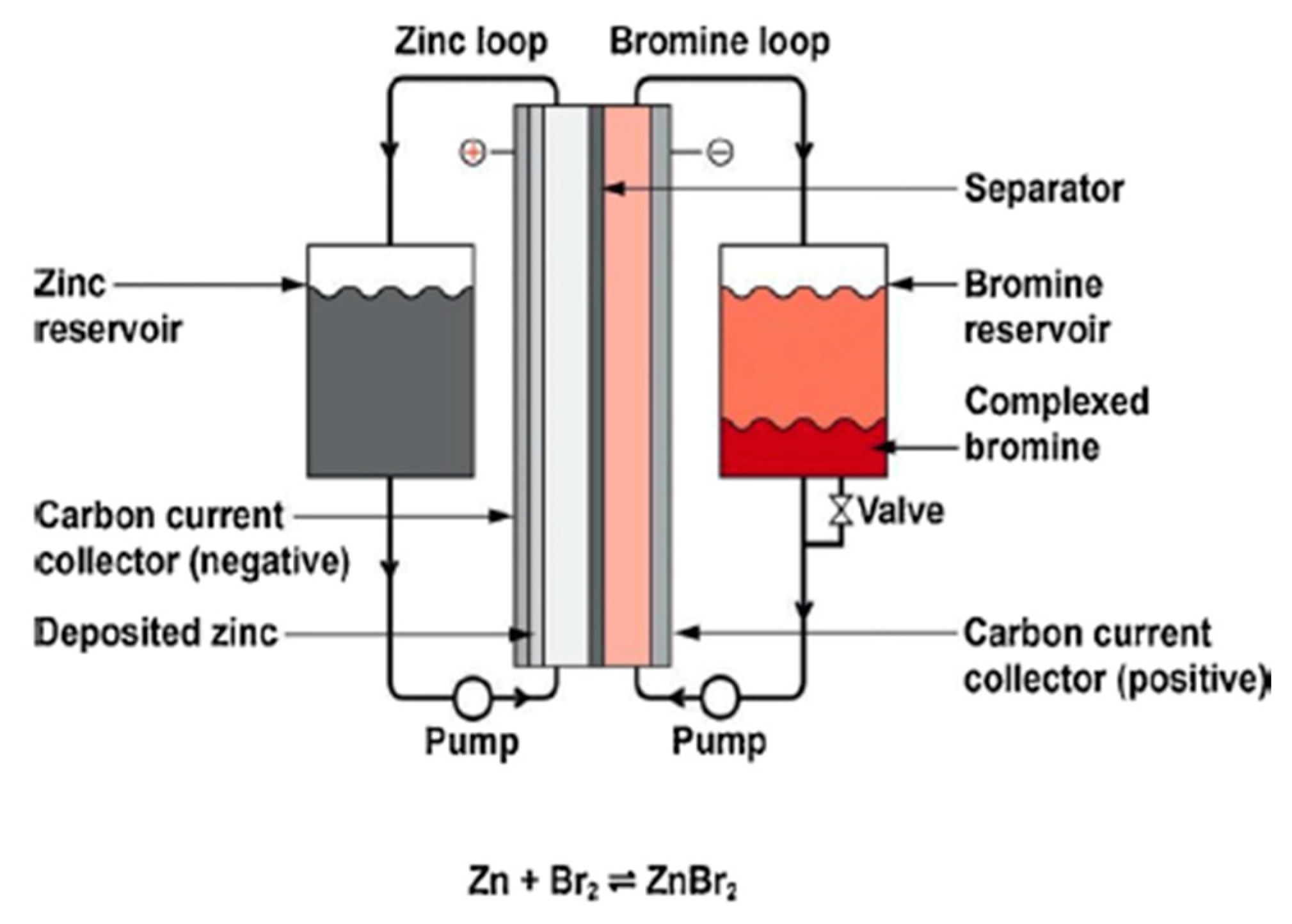
In Na-NiCl2 batteries, a beta-alumina electrolyte is employed; however, the cathode is nickel chloride submerged in sodium aluminum chloride (NaAlCl4), a molten salt that conducts sodium ions, as opposed to a sulfur electrode [35]. Nickel metal and sodium chloride are created when sodium reacts with nickel chloride during discharge [35,36]. The system still needs heating, insulation, and temperature control even though it operates at a lower temperature than Na-S batteries (300 °C) [37]. Compared to Na-S batteries, the energy density is higher, but the battery life is longer. Figure 9 depicts the chemistry and main parts of a sodium–nickel chloride battery.

3.5. Flow Batteries

Utility-scale energy storage has some promise thanks to flow batteries. There are many different compositions, but they all have energy-producing cells with electrode material stored remotely, making it possible for very large storage batteries to be made [38,39]. Vanadium redox batteries (VRB) are made up of cells with carbon composite electrodes submerged in a fluid containing aqueous acid and vanadium sulfate, with different valence states separated by an ion-selective membrane. At the positive electrode during discharge, V5+ is converted to V4+, while V2+ is converted to V3+ at the negative electrode. The volume of the vanadium sulfate solution, and hence the battery’s capacity, is potentially limitless because it is kept in a storage tank. Recharging causes reverse reactions, which replenish the materials. The batteries are complicated to use and made of heavy materials, but their expected lifespan is very lengthy. Only a few prototype systems have been implemented so far, and given the size of the battery, VRB batteries are only practical for utility energy storage. Figure 10 depicts the chemistry and main parts of a vanadium redox flow battery.
Another kind of flow battery is the zinc–bromine (Zn-Br2) battery, as shown in Figure 11. Zinc bromide is synthesized when Zn reacts with Br2 within the cell. Br2 is injected into cells with carbon electrodes and a microporous plastic separator in an aqueous solution as an organic complexing agent [40,41].
Metallic Zn is formed on charging, and while Br2 is housed in tanks, the Zn electrode enforces a limit on the capacity for any specific design. The price is cheaper than VRB batteries, but the average lifetime is less. The discharge of bromine is a perceived threat that must be avoided. Zn-Br2 batteries, like other flow batteries, have only been employed in moderate numbers for utility usage. There are a few similar types of flow batteries, such as iron–chromium batteries; however, they are not broadly utilized.
The technical comparison of the aforementioned battery technologies has been tabulated as demonstrated in Table 2.

4. Battery Storage Systems Applications

The fixed resolutions comprising deconcentrated generation, management, and control tactics for power supervision and storage assisted to establish the concept of smart networks. The intellect of these networks is not just about the reduction the technical restrictions but also manufacturing the electric system to be greener, more competent, compliant to the customer desires, and consequently cost-effective. These networks aggregate the employment of information technology personnel, allowing two-party communication between the energy network and the construction customers, which results in detection on both sides, making the network intelligent as they are more competent and elastic than the conventional energy network [42,43]. Consequently, intelligent networks unlock the industry to new utilization with comprehensive interdisciplinary influences due to their capability to safely provide and integrate more sustainable power sources, grid-based generators, and elegant buildings [43]. Hence, extraordinarily dependable communication will be imperative to transfer a substantial volume of information. Thus, communication and system engineering will play a substantial function in the integration of elegant buildings and energy systems [43]. Numerous alterations in the electric network have been taking place since the development of the smart network concepts, resulting from a reorganization in the sector and technological developments.
These amendments also produce regulative alterations and can generate numerous intrinsic advantages to energy generation networks through the amenities given by these networks. Nonetheless, energy storage is unconstrained in gathering long-term alterations in energy output generated by short-term irregular intrinsic renewable sources. These networks submit significant characteristics to the electrical network and consumers. Energy storage networks may have very different applications and capabilities and, thus, have a slow or fast response [43]; a few of these services as explained below.
The applications of BESS are highlighted below in summary format. The economic value proposition for some applications is presented, with formulas.

4.1. Regulation

Regulation involves handling energy flow with other command areas to merge planned flow and instant fluctuations in demand. The primary motive for regulation is to preserve frequency and voltage inside industry-conventional standards [44]. In realistic conditions, this application is marked by the constant balance between the provision and need of electricity, concerning the frequency or load, and the regulation of operating (low) and responsive powers (high) [45]. Voltage regulation is a necessity in the electric energy system [45]. This application comprises the supervision of reactivity, generated by grid-connected apparatus that produces, sends, or employs electricity and frequently has or presents features for instance inductors and capacitors in an electric circuit [44]. Hence, these energy plants (reactive energy—VAR) might either be substituted by energy storage tactically located within the network at central positions or across the supplied method, embedding various VAR support storage networks closely to large loads [44].
Furthermore, the frequency response operation, which is like regulation, excludes the fact that it reacts to system requirements in an even shorter time, in the order of seconds to below one minute, when there is an unexpected loss of frequency response [45].

4.2. Integration of Renewable Power Generation

Energy storage completes load smoothing produced by the intermittence of wind and PV networks [46]. In this operation, within minutes, there is a load ramp support to react to a fast or at random floating load outline [46]. Consequently, renewable energy production can be controlled, smoothed, and expeditious, particularly in distant areas [46]. Additionally, diverse modes of process must merge to reach feasibility, for instance, energy quality control, load supervision, and others are considered next [46].

4.3. Energy Arbitrage
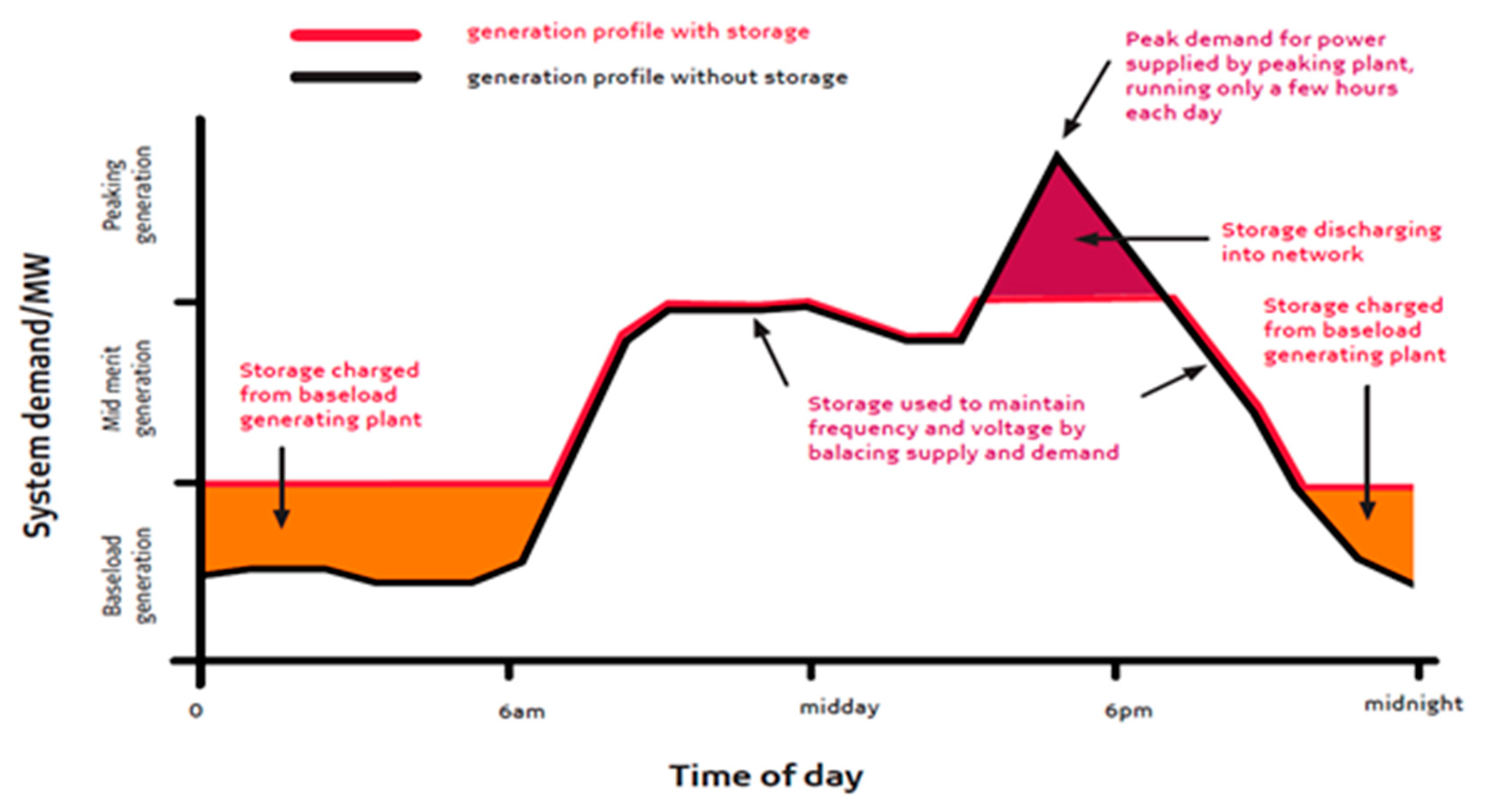
Energy arbitration is where energy is kept throughout low production expense/tariff time for transmission at high production cost/tariff time. Accordingly, the network’s incompetence does not surpass the cost distinction, so the business case could be positive. The general formulae for value realization over the life of the asset are shown in Equation (1).
V a l u e = E n e r g y   S u p p l i e d × P e a k   R a t e E n e r g y   C o n s u m e d × O f f P e a k   r a t e
where,
E n e r g y   S u p p l i e d = E n e r g y   C o n s u m e d × E f f i c i e n c y   o f   B E S S

4.4. Peak Clipping

The release of energy at a certain volume factor during peak times can be employed to lessen peaking volume thus saving costs. The general formulae for value realization over the life of the asset to the generator are expressed as follows in Equation (2).
V a l u e = D e m a n d   R e d u c t i o n × D i f f e r e n t i a l   C o s t   o f   P e a k i n g   G e n e r a t i o n  
The general formulae for value realization over the life of the asset to the end consumer are expressed as follows in Equation (3).
V a l u e = D e m a n d   R e d u c t i o n × D e m a n d   C h a r g e   ( R / k W h )
The energy arbitrage and peak shaving are demonstrated in Figure 12.

4.5. Spinning/Instantaneous Reserves

BESS techniques have an extremely quick response, far faster than synchronous networks [47]. Fast distribution can have extra profits, mainly when linked with traditional non-instantaneous spinning resources, for example, gas turbines that may well take minutes to achieve rated output.

4.6. Frequency Support

BESS volume can be employed in energy mode (short duration), as a source or load, to supply fast volume support that can capture frequency excursions [48]. Frequency must function under the rate of change in the frequency curve. The general formula for value realization is shown in Equation (4).
V a l u e = I n v e s t m e n t   i n   T r a d i t i o n a l   S p i n n i n g   R e s e r v e s E q u i v a l e n t   B E S S   l i f e c y c l e   c o s t

4.7. Voltage Support

Equally, BESS volume can be employed in energy mode (short duration), as a generator or load, to supply fast voltage aid that can restrain frequency excursions. This can be battery-operated volume energy or non-battery-reactive energy in static VAR compensator mode.

4.8. Quality of Supply/Critical Power

BESS can be employed to ride short-duration quality of provision phenomena for instance voltage dips and flicker.

4.9. Capex Deferral

BESS can be employed to increase volume and support the network at crucial periods of the day, thus evading what can be an expensive investment in infrastructure development. The general formula for value realization is shown in Equation (5).
V a l u e = i n v e s t m e n t   i n   t r a d i t i o n a l   i n f r a s t r u c t u r e E q u i v a l e n t   B E S S   l i f e c y c l e   c o s t

4.10. PV Smoothing

PV smoothing refers to the practice of storing solar energy throughout the day for release at peak demand periods. With the help of this operation, services can maximize the amount of solar energy that the network will allow, allowing for both provision and storage. The non-violation of network inertia constraints is the main emphasis of everything here [49].

4.11. Wind Energy Firming

It is possible to size battery storage to accommodate varying wind production. The BESS is charged when the wind exceeds the set limit. When production falls below a certain threshold, it is released. In a manner similar to PV, adequate storage can render wind dispatchable.

4.12. Backup Supply

In UPS mode, a BESS solution can be employed as a backup energy source. There are numerous engineering production inroads in the SA market in the backup energy and energy security market [50]:
 - 
Lithium-ion (Li-ion) and lead–acid battery techniques, which are the most attempted and verified, remain the leaders in this market;
 - 
There are other storage skills available, but they either do not have present pilot projects in SA, or they have not exhibited promise in medium-to-large-measure storage applications when compared with their direct competitors.
A look into the BESS market in South Africa is illustrated in Table 3.
Due to the fact that networks are typically developed specifically for each application, hydrogen storage and vanadium redox flow batteries have not gained the necessary access to markets. These situations often involve substantial capital-scale applications, and the viability of the project is determined throughout its life cycle by the levelized cost of storage (LCOS). Initial analysis shows that lithium iron technology may have the most significant commercial presence. Lithium iron phosphate (LiFePO4) is currently the dominant technology, mostly because of its low production costs, established performance rankings, and evaluated effective stability. The majority of Li-ion-linked base systems are used in off-network applications where the end-user has limited or no access to service energy or where energy security is crucial for the continuity of business operations. These outcomes often take the shape of a hybrid mini-network with integrated renewable production (mostly solar PV), diesel production, and battery storage (see this case study). Energy storage system installation has increased in high-end homes and businesses as a way to mitigate the effects of load shedding.
Some of the technical challenges can be circumvented as tabulated in Table 4 using the relevant application, control algorithm and duration, which is critical.
It can be observed that by using a Li-ion battery over a Pb acid battery, the issues of power smoothing, load shaving, frequency regulation, PV plant dispatchability and energy arbitration can be circumvented.

5. Current Status and Some Real PV-Battery Projects

This segment examines some South African situations wherein energy storage systems have been used conjointly with PV generation, highlighting their modes of operation, energy storage forms, and current outcomes.

5.1. Canadian Farm

The Canadian farm, located in Lephalale, Limpopo, South Africa has a System size (kW + kWh) of about 200–1200 kWh and is equipped with a BESS as described in Table 5.

5.2. Botha Huis

Botha huis, located in Mosselbay, South Africa has a capacity of 13.2 kWp (kW + kWh) and is equipped with a battery energy storage system as described in Table 6.

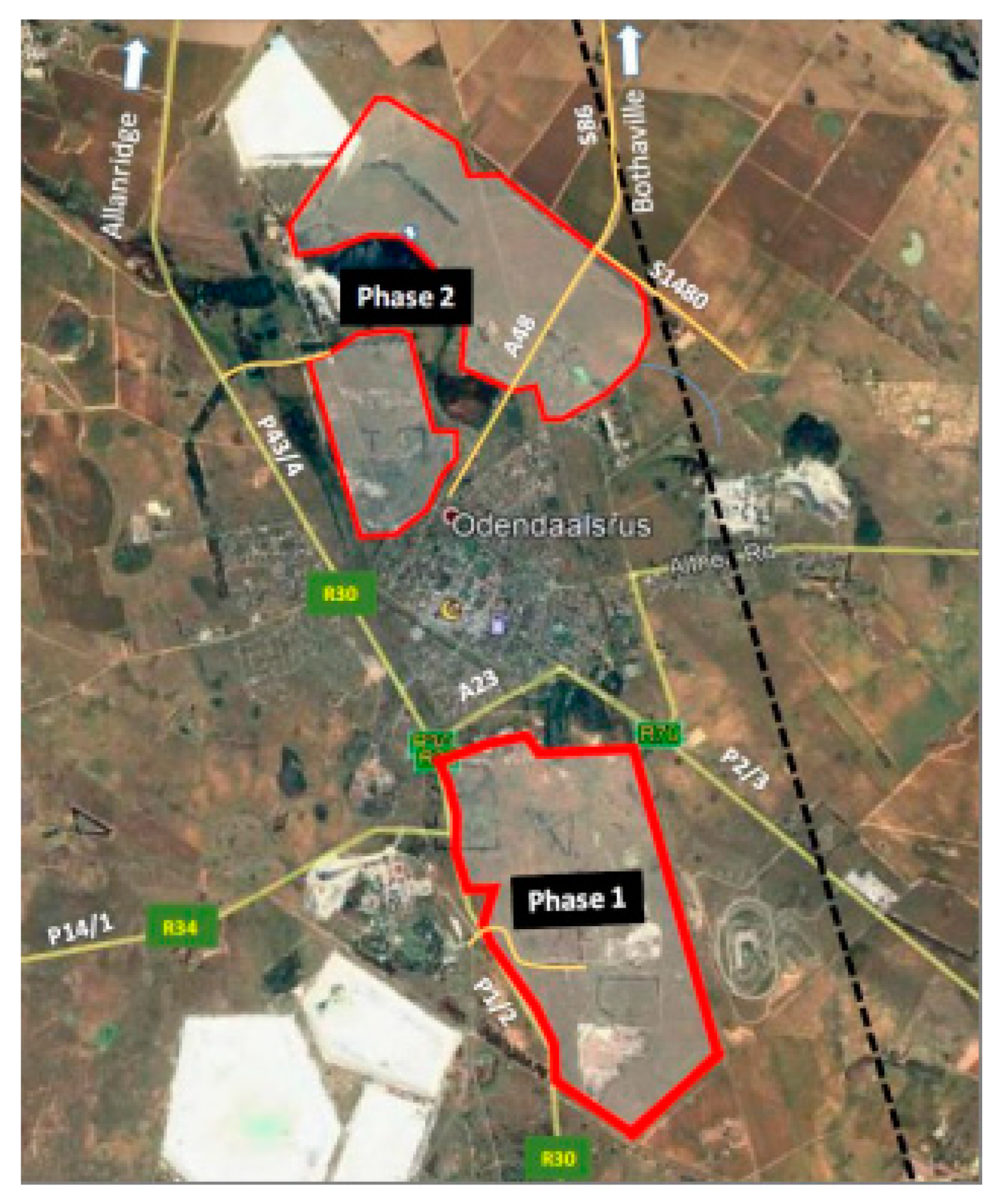
5.3. Matjhabeng Solar PV with Battery Energy Storage Systems Project

The Matjhabeng 400 MW Solar Photovoltaic Power Plant with 80 MW (320 MWh) battery energy storage systems (henceforth referred to as the “Project”), which is situated north and south of the town of Odendaalsrus in the Free State Province, has been proposed by SunElex Energy (Pty) Ltd. (the Applicant). The planned project will be designed to meet the energy needs of the Matjhabeng Local Municipality and will produce electricity for delivery to the regional or global grid. Locality map of the project’s Phase 1 and Phase 2 sites show in Figure 13. The two (2) phases listed below will be used to develop the proposed utility-scale project:
  • Phase 1: A 200 MW solar photovoltaic system with a 40 MW (160 MWh) battery energy storage system (referred to as the “Phase 1 Site”), which is located on a site south of Odendaalsrus;
  • Phase 2: 200 MW of solar photovoltaic capacity with a 40 MW (160 MWh) battery energy storage system (on the site north of Odendaalsrus, referred to as the “Phase 2 Site” in the following). The project’s electrical output will be fed into Eskom’s pre-existing 132 kV distribution network.

5.4. Planned BESS Projects

Eskom, a state-owned enterprise has recognized 24 sites in the Western Cape Province, South Africa, where the planned BESS projects will be realized with a capacity of about 148.5 MW. The following criteria were contemplated in the choice of fitting sites:
 - 
Vicinity of electricity clienteles to existing PV generators;
 - 
Decrease in energy supply losses;
 - 
Peak load abatement on severely loaded network components;
 - 
Abatement in congestion of upstream high-voltage networks;
 - 
Enhancement of local network characteristics and quality of supply;
 - 
Peak load abatement where the peak load is coincident with the national system peak (i.e., winter evenings);
 - 
Accessibility of sufficient MV connection capacity for the BESS;
 - 
Accessibility of sufficient space at the substation for the deployment of BESS containers.
A view of one of the sites planned for BESS implementation, Eskom Paleisheuwel, is shown in Figure 14.

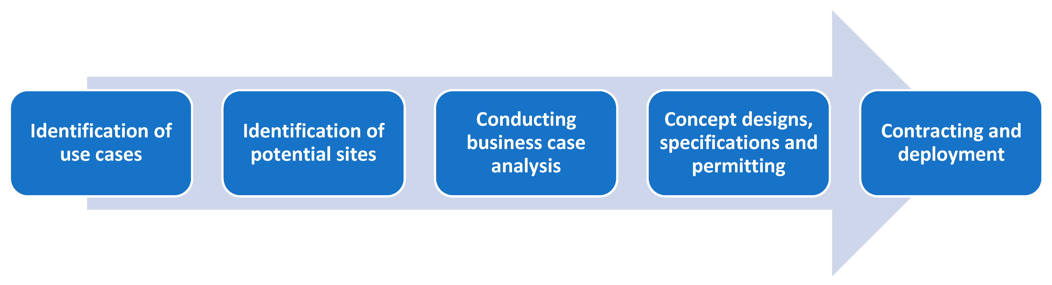
6. Deployment of Utility-Scale Battery Energy Storage

The Eskom BESS project involves implementing outcomes at several locations in various operating units (OUs). Sizes of the results range from 1 MW to 60 MW. The standard size of an installation is 4 MW/16 MWh, which equals an estimated total of 90 installations. To optimize the usefulness of the BESS, all results will have a primary function and supporting roles that are “stacked benefits” in nature. As an illustration, a unit designed primarily for capex deferral during peak times in the winter will be available for operations such as frequency support at any time and peak clipping in the summer. The maximum discharge period will be 4 h. Figure 15 illustrates the steps used to appear in a technical investigation.
Step 1: 
 
Wherever possible, supply-delayed investment and congestion supervision were given priority because these are the most enticing applications.
Step 2: 
 
Active OU recognized potential sites, where appropriate. Substations located in electrically distant operational units were chosen in cases where local improvements could not be immediately realized. Prioritizing areas that relieve congestion upstream and reduce failures was one endeavor. In addition to replacing peak energy (kWh) and demand, these locations will supply gains and losses (kW).
Step 3: 
 
In this stage, the business benefit of installing BESS is compared to other viable options (such as adding new supply/transmission substations and feeders, installing voltage regulators, adding more peaking power generators, etc.), as well as whether the investment will be recouped within a reasonable amount of time. The case for the project is made on the basis of both direct and indirect benefits, such as lower distribution costs for bulk purchases and lower production costs overall.
Step 4: 
 
Conducting technical due diligence on potential locations is the first stage of this cycle. This entails showcasing a number of system planning studies, such as the worst case (maximum charging and discharging) load flows, dynamic time-series training, and quality of distribution studies. Conceptual plans for efficient locations have been carried out. These are based on standard BESS yard and station yard layouts, but the winning engineering, procurement, and construction (EPC) contractor are responsible for finishing them at the detail design stage. This phase also saw the creation and approval of the following technical specifications:
  • BESS equipment;
  • AC equipment;
  • General BESS and substation yard;
  • Protection and control;
  • Distributed energy resources management system (DERMS);
  • Application performance monitoring (APM) tool.
In order to ensure a smooth transition between system circumstances and BESS stationing, the DERMS will be implemented into the SCADA. A “BESS fleet” will be successfully run by it. The life management of the BESS divisions is important, since some interactions tend to diminish over time, making the technical advancements less fully implementable. Therefore, it is crucial to check the unit’s longevity, especially the chemical storage unit. The APM tool is used to achieve this. Authorizing involves locating land and directing environmental impact assessments in accordance with the relevant laws.
Step 5: 
 
The preparation of bid documents (bills of quantities and assessment criteria) in accordance with the provided templates is part of the contracting phase. Eskom has provided the necessary technical paperwork and validated the possibility for each location. The list of required documentation includes, among other things:
  • A planning report showing the use case;
  • Business case and system limits;
  • System diagrams for the anticipated BESS and substation yards;
  • Several service technical conditions.
Primary assessment, technical assessment, and finally economic development assessment make up the evaluation criteria. The development stage takes into account energy and capital costs.

7. Results and Discussion

In this section, to provide a significant innovation and contribution in the field of implementing battery energy storage for photovoltaic applications, a techno-economic analysis of two battery technologies incorporated with the Photovoltaic Grid-Connected System is carried out by adopting the HOMER-Pro-software with contemplation of actual load profiles and resource data. Consequently, the BESS-PV incorporated with a Li-ion battery brought forth a LCOE of 5.46 R/kWh in comparison with the BESS-PV system embedded with a Pb-acid battery postulating a LCOE of 5.8 R/kWh. Conversely, a total present cost (TPC) of the BESS-PV system with Li-ion batteries turned out to have a total of about R245,774 in comparison to the BESS-PV system with Pb-acid battery yielded a TPC of R257,841. The levelized cost of electricity (LCOE) outcome of the current study is proved to be favorable. The comparative analysis of Pb-acid and Li-ion battery technology in reference to various measure of effectiveness is tabulated in Table 7.
As observed above, for each type of BESS with similar input PV, the number of batteries, converter parameters postulated, the state of charge (%), battery capacity (Ah), and lifetime (years) feature an output of Li-ion batteries (100%, 167, 11) is discovered to be enhanced compared to a Pb-acid battery (100%, 83, 4). Moreover, as shown in Table 8, it could be absorbed as evidence for Li-ion batteries to be exploited in solar PV generation due to their enhanced energy capability.
By this investigation, the results lead to the conclusion that the BESS-PV system with Li-ion batteries necessitates about 41% fewer batteries in comparison to Pb-acid batteries and is supplementary in the establishment of an unswerving power source with lower expenditure. Furthermore, Li-ion battery technology delivered lower TPC and LCOE, and the BESS-PV system that has a higher solar PV fraction necessitates a greater number of batteries reciprocally. Generally, considering the standard application scenario investigated, Li-ion batteries are ascertained to be lucrative in both technical and economic countenances, and thus, they are advisable as a fill-in workable solution in combating the problem of load shedding in South Africa.

8. Conclusions

In the South African context, as well as in many other countries, electricity supply capacity could be best increased by promoting the diversity of energy sources in the generation. In this generation mix, renewable energies and particularly PV solar are one of the leading renewable sources of energy despite challenges related to their inability to meet the base load demand of electricity. Therefore, large-scale PV solar projects for reliable electricity supply require both in-depth knowledge pursuit as well as financial investment in energy storage technologies. This work discusses the knowledge gap in the three critical areas concerning the implementation of large-scale electrical energy storage in the South African context.
Based on the proposed case scenario, Li-ion batteries are ascertained to be lucrative in both technical and economic countenances, and thus, they are advisable as a fill-in workable solution in combating the problem of load shedding in South Africa. Some of the technical challenges, i.e., output power smoothing, load shaving, frequency regulation, PV plant dispatchability and energy arbitration can be circumvented using the control algorithms furnished and their corresponding duration thereof.
As a proposal, further investigations should be conducted in order to crack the problem of economic viability under distinctive application set-ups.

Author Contributions

B.A.T., conceptualized, carried out the investigation, wrote and prepared the article. P.N.B. was responsible for reviewing, editing, and drafting closing remarks of the article. The published version of the article has been reviewed and approved by all authors. All authors have read and agreed to the published version of the manuscript.

Funding

This research received no external funding.

Institutional Review Board Statement

Not applicable.

Informed Consent Statement

Not applicable.

Data Availability Statement

Not applicable.

Conflicts of Interest

The authors declare no conflict of interest.

References

  1. CSIR. Load Shedding Statistics. December 2021. Available online: https://www.csir.co.za/load-shedding-statistics (accessed on 17 July 2022).
  2. Bashe, M.; Shuma-Iwisi, M.; van Wyk, M.A. Assessing the Costs and Risks of the South African Electricity Portfolio: A Portfolio Theory Approach. J. Energy S. Afr. 2016, 27, 91–100. [Google Scholar] [CrossRef]
  3. Bruwer, J.P. South African Residential Electricity Price Increase between 2013 and 2020: An Online Desktop Study. Bus. Re-Solut. 2021. [Google Scholar] [CrossRef]
  4. Dauda, L.; Long, X.; Mensah, C.N.; Salman, M.; Boamah, K.B.; Ampon-Wireko, S.; Dogbe, C.S.K. Innovation, trade openness and CO2 emissions in selected countries in Africa. J. Clean. Prod. 2021, 281, 125143. [Google Scholar] [CrossRef]
  5. Friedrich, E.; Trois, C. GHG emission factors developed for the collection, transport and landfilling of municipal waste in South African municipalities. Waste Manag. 2013, 33, 1013–1026. [Google Scholar] [CrossRef]
  6. Department of Mineral Resources and Energy. Integrated Resource Plan (IRP2019). Government Notice; October 2019. Available online: http://www.energy.gov.za/IRP/2019/IRP-2019.pdf (accessed on 17 July 2022).
  7. Department of Mineral Resources and Energy. IRP Update Draft Report 2018. Government Notice; August 2018. Available online: http://www.energy.gov.za/IRP/irp-update-draft-report2018/IRP-Update-2018-Draft-for-Comments.pdf (accessed on 17 July 2022).
  8. Gür, T.M. Review of electrical energy storage technologies, materials and systems: Challenges and prospects for large-scale grid storage. Energy Environ. Sci. 2018, 11, 2696–2767. [Google Scholar] [CrossRef]
  9. Jiang, J.; Li, Y.; Liu, J.; Huang, X.; Yuan, C.; Wen, X.; Lou, D. Recent Advances in Metal Oxide-based Electrode Architecture Design for Electrochemical Energy Storage. Adv. Mater. 2012, 24, 5166–5180. [Google Scholar] [CrossRef]
  10. Bruce, P.; Freunberger, S.; Hardwick, L.; Tarascan, J.M. Li–O2 and Li–S batteries with high energy storage. Nat. Mater. 2012, 11, 19–29. [Google Scholar] [CrossRef]
  11. Sabihuddin, S.; Kiprakis, A.E.; Mueller, M. A Numerical and Graphical Review of Energy Storage Technologies. Energies 2015, 8, 172–216. [Google Scholar] [CrossRef]
  12. Agyenim, F.; Hewitt, N.; Eames, P.; Smyth, M. A review of materials, heat transfer and phase change problem formulation for latent heat thermal energy storage systems (LHTESS). Renew. Sustain. Energy Rev. 2010, 14, 615–628. [Google Scholar] [CrossRef]
  13. Zahedi, A. Maximizing solar PV energy penetration using energy storage technology. Renew. Sustain. Energy Rev. 2011, 15, 866–870. [Google Scholar] [CrossRef]
  14. Mararakanye, N.; Bekker, B. Renewable energy integration impacts within the context of generator type, penetration level and grid characteristics. Renew. Sustain. Energy Rev. 2019, 108, 441–451. [Google Scholar] [CrossRef]
  15. Rana, M.M.; Romlie, M.F.; Abdullah, M.F.; Uddin, M.; Sarkar, M.R. A novel peak load shaving algorithm for isolated microgrid using hybrid PV-BESS system. Energy 2021, 234, 121157. [Google Scholar] [CrossRef]
  16. Korjani, S.; Casu, F.; Damiano, A.; Pilloni, V.; Serpi, A. An online energy management tool for sizing integrated PV-BESS systems for residential prosumers. Appl. Energy 2022, 313, 118765. [Google Scholar] [CrossRef]
  17. Peng, C.-Y.; Kuo, C.-C.; Tsai, C.-T. Optimal Configuration with Capacity Analysis of PV-Plus-BESS for Behind-the-Meter Application. Appl. Sci. 2021, 11, 7851. [Google Scholar] [CrossRef]
  18. Gush, T.; Kim, C.-H.; Admasie, S.; Kim, J.-S.; Song, J.-S. Optimal Smart Inverter Control for PV and BESS to Improve PV Hosting Capacity of Distribution Networks Using Slime Mould Algorithm. IEEE Access 2021, 9, 52164–52176. [Google Scholar] [CrossRef]
  19. Nair, U.R.; Sandelic, M.; Sangwongwanich, A.; Dragičević, T.; Costa-Castelló, R.; Blaabjerg, F. An Analysis of Multi Objective Energy Scheduling in PV-BESS System under Prediction Uncertainty. IEEE Trans. Energy Convers. 2021, 36, 2276–2286. [Google Scholar] [CrossRef]
  20. Thirugnanam, K.; Kerk, S.K.; Yuen, C.; Liu, N.; Zhang, M. Energy Management for Renewable Microgrid in Reducing Diesel Generators Usage with Multiple Types of Battery. IEEE Trans. Ind. Electron. 2018, 65, 6772–6786. [Google Scholar] [CrossRef]
  21. Venu, C.; Riffonneau, Y.; Bacha, S.; Baghzouz, Y. Battery Storage System sizing in distribution feeders with distributed photovoltaic systems. In Proceedings of the 2009 IEEE Bucharest PowerTech, Bucharest, Romania, 28 June–2 July 2009; pp. 1–5. [Google Scholar] [CrossRef]
  22. Wang, Z.; Gu, C.; Li, F.; Bale, P.; Sun, H. Active Demand Response Using Shared Energy Storage for Household Energy Management. IEEE Trans. Smart Grid 2013, 4, 1888–1897. [Google Scholar] [CrossRef]
  23. Kumar, D.; Zare, F.; Ghosh, A. DC Microgrid Technology: System Architectures, AC Grid Interfaces, Grounding Schemes, Power Quality, Communication Networks, Applications, and Standardizations Aspects. IEEE Access 2017, 5, 12230–12256. [Google Scholar] [CrossRef]
  24. Lezhniuk, P.; Komar, V.; Rubanenko, O. Information Support for the Task of Estimation the Quality of Functioning of the Electricity Distribution Power Grids with Renewable Energy Source. In Proceedings of the 2020 IEEE 7th International Conference on Energy Smart Systems (ESS), Kyiv, Ukraine, 12–14 May 2020; pp. 168–171. [Google Scholar] [CrossRef]
  25. 450-2020; IEEE Recommended Practice for Maintenance, Testing, and Replacement of Vented Lead-Acid Batteries for Stationary Applications—Redline. IEEE: Manhattan, NY, USA, 2021; pp. 1–115.
  26. P1361/D4; IEEE Draft Guide for Selection, Charging, Test and Evaluation of Lead-Acid Batteries Used in Stand-Alone Photovoltaic (PV) Systems. IEEE: Manhattan, NY, USA, 2013; pp. 1–41.
  27. 1188-2005; IEEE Recommended Practice for Maintenance, Testing, and Replacement of Valve-Regulated Lead-Acid (VRLA) Batteries for Stationary Applications—Redline. IEEE: Manhattan, NY, USA, 2006; pp. 1–49.
  28. Li, T.; Chen, Y.; Gou, H.Y.; Chen, X.Y.; Tang, M.G.; Lei, Y. A DC Voltage Swell Compensator Based on SMES Emulator and Lead-Acid Battery. IEEE Trans. Appl. Supercond. 2019, 29, 1–4. [Google Scholar] [CrossRef]
  29. Freitas, D.C.C.; de Moraes, J.L.; Neto, E.C.; Sousa, J.R.B. Battery Charger Lead-Acid using IC BQ2031. IEEE Lat. Am. Trans. 2016, 14, 32–37. [Google Scholar] [CrossRef]
  30. McKeon, B.B.; Furukawa, J.; Fenstermacher, S. Advanced Lead–Acid Batteries and the Development of Grid-Scale Energy Storage Systems. Proc. IEEE 2014, 102, 951–963. [Google Scholar] [CrossRef]
  31. Chiu, H.; Lin, L.; Pan, P.; Tseng, M. A novel rapid charger for lead-acid batteries with energy recovery. IEEE Trans. Power Electron. 2006, 21, 640–647. [Google Scholar] [CrossRef]
  32. Hannan, M.A.; Hoque, M.M.; Hussain, A.; Yusof, Y.; Ker, P.J. State-of-the-Art and Energy Management System of Lithium-Ion Batteries in Electric Vehicle Applications: Issues and Recommendations. IEEE Access 2018, 6, 19362–19378. [Google Scholar] [CrossRef]
  33. Zhang, W.; Wang, L.; Wang, L.; Liao, C.; Zhang, Y. Joint State-of-Charge and State-of-Available-Power Estimation Based on the Online Parameter Identification of Lithium-Ion Battery Model. IEEE Trans. Ind. Electron. 2022, 69, 3677–3688. [Google Scholar] [CrossRef]
  34. Al-Humaid, Y.M.; Khan, K.A.; Abdulgalil, M.A.; Khalid, M. Two-Stage Stochastic Optimization of Sodium-Sulfur Energy Storage Technology in Hybrid Renewable Power Systems. IEEE Access 2021, 9, 162962–162972. [Google Scholar] [CrossRef]
  35. Saruta, K. Long-term performance of sodium sulfur battery. In Proceedings of the 2016 IEEE 2nd Annual Southern Power Electronics Conference (SPEC), Auckland, New Zealand, 5–8 December 2016; pp. 1–5. [Google Scholar] [CrossRef]
  36. Hatta, T. Applications of sodium-sulfur batteries. In PES T&D 2012; IEEE: Manhattan, NY, USA, 2012; pp. 1–3. [Google Scholar] [CrossRef]
  37. Manzoni, R. Sodium Nickel Chloride batteries in transportation applications. In Proceedings of the 2015 International Conference on Electrical Systems for Aircraft, Railway, Ship Propulsion and Road Vehicles (ESARS), Aachen, Germany, 3–5 March 2015; pp. 1–6. [Google Scholar] [CrossRef]
  38. Marcondes, A.; Scherer, H.F.; Salgado, J.R.C.; de Freitas, R.L.B. Sodium-nickel chloride single cell battery electrical model—Discharge voltage behavior. In Proceedings of the 2019 Workshop on Communication Networks and Power Systems (WCNPS), Brasilia, Brazil, 3–4 October 2019; pp. 1–4. [Google Scholar] [CrossRef]
  39. Benato, R.; Sessa, S.D.; Necci, A.; Palone, F. A general electric model of sodium-nickel chloride battery. In Proceedings of the 2016 AEIT International Annual Conference (AEIT), Capri, Italy, 5–7 October 2016; pp. 1–6. [Google Scholar] [CrossRef]
  40. Challapuram, Y.R.; Quintero, G.M.; Bayne, S.B.; Subburaj, A.S.; Harral, M.A. Electrical Equivalent Model of Vanadium Redox Flow Battery. In Proceedings of the 2019 IEEE Green Technologies Conference (GreenTech), Lafayette, LA, USA, 3–6 April 2019; pp. 1–4. [Google Scholar] [CrossRef]
  41. Vins, M.; Sirovy, M. Assessing Suitability of Various Battery Technologies for Energy Storages: Lithium-ion, Sodium-sulfur and Vanadium Redox Flow Batteries. In Proceedings of the 2020 International Conference on Applied Electronics (AE), Pilsen, Czech Republic, 8–9 September 2020; pp. 1–5. [Google Scholar] [CrossRef]
  42. Lim, J.-U.; Lee, S.-J.; Kang, K.-P.; Cho, Y.; Choe, G.-H. A modular power conversion system for zinc-bromine flow battery based energy storage system. In Proceedings of the 2015 IEEE 2nd International Future Energy Electronics Conference (IFEEC), Taipei, Taiwan, 1–4 November 2015; pp. 1–5. [Google Scholar] [CrossRef]
  43. Nakatsuji-Mather, M.; Saha, T.K. Zinc-bromine flow batteries in residential electricity supply: Two case studies. In Proceedings of the 2012 IEEE Power and Energy Society General Meeting, San Diego, CA, USA, 22–26 July 2012; pp. 1–8. [Google Scholar] [CrossRef]
  44. Lawder, M.T.; Suthar, B.; Northrop, P.W.C.; De, S.; Hoff, C.M.; Leitermann, O.; Crow, M.L.; Santhanagopalan, S.; Subramanian, V.R. Battery Energy Storage System (BESS) and Battery Management System (BMS) for Grid-Scale Applications. Proc. IEEE 2014, 102, 1014–1030. [Google Scholar] [CrossRef]
  45. 2030.2.1-2019; IEEE Guide for Design, Operation, and Maintenance of Battery Energy Storage Systems, Both Stationary and Mobile, and Applications Integrated with Electric Power Systems. IEEE: Manhattan, NY, USA, 2019; pp. 1–45. [CrossRef]
  46. Wong, Y.S.; Lai, L.L.; Gao, S.; Chau, K.T. Stationary and mobile battery energy storage systems for smart grids. In Proceedings of the 2011 4th International Conference on Electric Utility Deregulation and Restructuring and Power Technologies (DRPT), Weihai, China, 6–9 July 2011; pp. 1–6. [Google Scholar] [CrossRef]
  47. Shi, M.; Hu, J.; Han, H.; Yuan, X. Design of Battery Energy Storage System based on Ragone Curve. In Proceedings of the 2020 4th International Conference on HVDC (HVDC), Xi’an, China, 6–9 November 2020; pp. 37–40. [Google Scholar] [CrossRef]
  48. Akhil, A. Trends and status of battery energy storage for utility applications. In Proceedings of the Tenth Annual Battery Conference on Applications and Advances, Long Beach, CA, USA, 10–13 January 1995; pp. 273–277. [Google Scholar] [CrossRef]
  49. Helling, F.; Götz, S.; Weyh, T. A battery modular multilevel management system (BM3) for electric vehicles and stationary energy storage systems. In Proceedings of the 2014 16th European Conference on Power Electronics and Applications, Lappeenranta, Finland, 26–28 August 2014; pp. 1–10. [Google Scholar] [CrossRef]
  50. Akhil, A.; Kraft, S.; Symons, P.C. Market feasibility study of utility battery applications: Penetration of battery energy storage into regulated electric utilities. In Proceedings of the Twelfth Annual Battery Conference on Applications and Advances, Long Beach, CA, USA, 14–17 January 1997; pp. 195–200. [Google Scholar] [CrossRef]
  51. Li, X.; Hui, D.; Lai, X. Battery Energy Storage Station (BESS)-Based Smoothing Control of Photovoltaic (PV) and Wind Power Generation Fluctuations. IEEE Trans. Sustain. Energy 2013, 4, 464–473. [Google Scholar] [CrossRef]
  52. Oudalov, A.; Cherkaoui, R.; Beguin, A. Sizing and Optimal Operation of Battery Energy Storage System for Peak Shaving Application. In Proceedings of the 2007 IEEE Lausanne Power Tech, Lausanne, Switzerland, 1–5 July 2007; pp. 621–625. [Google Scholar] [CrossRef]
  53. Mejía-Giraldo, D.; Velásquez-Gomez, G.; Muñoz-Galeano, N.; Cano-Quintero, J.B.; Lemos-Cano, S. A BESS Sizing Strategy for Primary Frequency Regulation Support of Solar Photovoltaic Plants. Energies 2019, 12, 317. [Google Scholar] [CrossRef]
  54. Gilmanova, A.; Wang, Z.; Gosens, J.; Lilliestam, J. Building an internationally competitive concentrating solar power industry in China: Lessons from wind power and photovoltaics. Energy Sources Part B Econ. Plan. Policy 2021, 16, 515–541. [Google Scholar] [CrossRef]
  55. Berger, M.; Kocar, I.; Farantatos, E.; Haddadi, A. Dual Control Strategy for Grid-tied Battery Energy Storage Systems to Comply with Emerging Grid Codes and Fault Ride through Requirements. J. Mod. Power Syst. Clean Energy 2022, 10, 977–988. [Google Scholar] [CrossRef]
  56. Li, J.; You, H.; Qi, J.; Kong, M.; Zhang, S.; Zhang, H. Stratified Optimization Strategy Used for Restoration with Photovoltaic-Battery Energy Storage Systems as Black-Start Resources. IEEE Access 2019, 7, 127339–127352. [Google Scholar] [CrossRef]
  57. Abdullah, W.S.W.; Osman, M.; Ab Kadir, M.Z.A.; Verayiah, R. Battery energy storage system (BESS) design for peak demand reduction, energy arbitrage and grid ancillary services. Int. J. Power Electron. Drive Syst. 2020, 11, 398–408. [Google Scholar] [CrossRef]
  58. Shi, L.; Fa, L.; Zhu, H.; Shi, J.; Wu, F.; He, W.; Wang, C.; Lee, K.Y.; Lin, K. Photovoltaic active power control based on BESS smoothing. IFAC-PapersOnLine 2019, 52, 443–448. [Google Scholar] [CrossRef]
  59. Zhuo, W. An Approximate Dynamic Programming Approach for Wind Power Dispatch in Wind Farms. In Proceedings of the 2018 37th Chinese Control Conference (CCC), Wuhan, China, 25–27 July 2018; pp. 7502–7508. [Google Scholar] [CrossRef]
Figure 1. The number of days of load shedding in South Africa.
Energies 15 05962 g001
Figure 2. Installed generation capacity in South Africa [1].
Energies 15 05962 g002
Figure 3. Solar PV self-consumption in South Africa.
Energies 15 05962 g003
Figure 4. Solar PV-Battery Energy Storage System.
Energies 15 05962 g004
Figure 5. Lead–acid battery construction.
Energies 15 05962 g005
Figure 6. Chemistry of lead–acid battery.
Energies 15 05962 g006
Figure 7. Chemistry and principal components of a lithium-ion battery.
Energies 15 05962 g007
Figure 8. Chemistry and principal components of a sodium–sulfur battery.
Energies 15 05962 g008
Figure 9. Chemistry and principal components of a sodium–nickel chloride battery.
Energies 15 05962 g009
Figure 10. Chemistry and principal components of a vanadium redox flow battery.
Energies 15 05962 g010
Figure 11. Chemistry and principal components of a zinc–bromine battery.
Energies 15 05962 g011
Figure 12. Peak shaving application for BESS.
Energies 15 05962 g012
Figure 13. Locality map of the project’s Phase 1 and Phase 2 sites.
Energies 15 05962 g013
Figure 14. Eskom Paleisheuwel, Western Cape province.
Energies 15 05962 g014
Figure 15. Process flow for the BESS project.
Energies 15 05962 g015
Table 1. Summary of recent related research works.
Ref. NoYearAddressed ChallengesLimitationsOutcomes
[15]2021Peak shavingIsolated microgrid systemAn algorithm was proposed and tested in a microgrid under different load conditions and PV generations.
[16]2022BESS-PV sizingHourly based energy generation and consumption profiles of 128 residentsAn energy management tool that suggests the BESS-PV sizes in accordance with answering a few straightforward energy consumption questions.
[17]2021Techno-economic analysisHOMER Grid softwareProvides behind-the-meter application of BESS-PV to efficaciously use renewable energy under the conditions of various portions of renewable energy.
[18]2021Inverter ControlMATLAB softwareReactive power control of smart inverters for BESS-PV to enhance the PV hosting capacity of distribution networks.
[19]2021Scheduling BESS-PV under uncertainty using model predictive control.
Current Study2022Peak shaving
PV-BESS sizing
Techno-economic analysis
BESS-PV market
BESS-PV Policies
Limited to South Africa BESS marketThe study aims to crucially examine BESS-PV capacities, shortcomings, constraints, and prospects for advancement. Probed areas of interest: choice of battery technology, mitigating miscellaneous power quality problems, optimal power system control, peak load shaving, South African BESS market and status of some Real BESS-PV projects.
Table 2. Technical comparison of battery technology in South Africa [23,24,25,26,27,28,29,30,31,32,33,34,35,36,37].
BatteryLead–Acid [23]Lithium-Ion [24]Sodium–Sulfur [25]Sodium–Nickel Chloride [26]Zinc–BROMINE [27]Vanadium Redox [28]
Energy density (Wh/L)80–90250–693110100–12015–6515–25
Nominal cell voltage (V)2.13.6/3.7/3.8/3.85, LiFePO4 3.21.78–2.2082.581.81.15–1.55
Specific energy
(Wh/kg)
35–40100–26515035060–8510–20
Self-discharge rate1%/day5%/day20%/day5–20%/day10%/day
Cycle durability<350400–120045004500>2000>12,000–14,000
Charge/discharge efficiency50–95%80–90%80%85–95%75.9%75–80%<
Key Challenges and Limitations
-
Low cycle and calendar life
-
Self-discharge
-
Lead toxicity
-
Fire protection
-
Large-scale controls
-
Self-discharge
-
Temp sensitivity
-
Long life
-
High number of charge and discharge cycles
-
Ability to discharge fully with no effects on the performance.
-
Low energy to size ratio
-
Operate at −20 °C to 60 °C
-
Recyclable
-
No fire hazards
-
−80% Depth of discharge
-
Expensive to use
-
Utility-scale to be proven
-
Low energy density (More Storage Space)
-
Electrolyte Leak and Mechanical Pumps
Table 3. BESS in South African Market [50].
Battery TechnologyApplicationMajor AdvantageCurrent LimitationsCost Range (R/kWh)Replacement Cost (R/kWh)Operation and Maintenance Cost (R/kWh/Year)Installation and Other Charges (EUR/kW)
Lead–AcidBackup power, UPS
-
Time tested
-
Economical
-
Advanced technology
-
Low energy density
-
Heavy
-
Damage the environment
-
Confined full discharge cycles
200–R10001773143.59426
Li-ionIndustrial-scale storage, Backup, UPS
-
High energy density
-
Minimal maintenance
-
Renowned in the market
-
Continually evolving
-
Expensive
-
Transport constraints
-
Advancing chemical combinations and developments
4000–R10,00070000287.17
Vanadium Redox Industrial-scale storage, Backup power
-
High depth of discharge
-
Adjustable electrolyte tanks
-
Unlimited storage potential
Accessing markets21,793–25,14623,000--
Table 4. BESS control algorithms and application.
Battery TechnologyApplicationControl AlgorithmDuration
Li-ionOutput power smoothing [51]ANN and grid-exchanged power profile8760 h
Peak generation/load shaving [52]Stochastic optimization-based battery operation
framework
24 h
Frequency regulation [53]State-machine-based coordinated control24 h
Voltage and frequency regulation [53]Fuzzy logic-based intelligent control technique18 s
PV plant dispatchability [54]Optimal power control strategy72 h
Fault-ride-through [55]Master–slave control mode18 s
Black start [56]Stratified optimization strategy60 min
Energy arbitrage [57]Classification-based scheme21 months
Output power smoothing [58]Simple moving average10 s
Frequency regulation [53]Step-wise inertial control method100 s
Lead–AcidFault-ride-through [55]Supervisory control system240 s
Black start [56]A copula selection and goodness-of-fit-based method80 min
Dynamic program approach [59]Dynamic program approach720 h
Table 5. BESS Canadian farm in Limpopo, South Africa.
TechnologyDescriptionQuantity
Batteries7.4 kWh Solar Md Li-ion156
Inverters8 kVA inverters SMA21
50 kW grid-tied inverter2
Dimension40-foot containerized solution
Annual energy stored (kWh)2200
Electricity tariff reduction (%)100
Table 6. BESS Botha Huis, Mosselbay, South Africa.
TechnologyDescriptionQuantity
PV modules270 W × 60 cells of polycrystalline49
BatteriesBYD B-Box2 × 2.56 kWh
Inverters8 kVA1
Annual energy yield (kWh)15,018.1 kWh
Annual energy stored (kWh)3312.2 kWh
Electricity tariff reduction (%)70
Table 7. Pb-acid vs. Li-ion battery technology in reference to various measure of effectiveness.
Battery TechnologyPV (kW)Number of Battery (Units)Converter (kW)Total TPC (R)LCOE (R)Operating CostPV Fraction (%)
Li-ion106524,577 5.4613,75790
Pb-acid10105257,8415.827,15791
Table 8. Pb-acid vs. Li-ion battery technology in reference to techno-economic analysis results.
Battery TechnologyEnergy in (kWh/Year)Energy Out (kWh/Year)Storage Depletion (kWh/Year)Losses (kWh/Year)Annual Throughput (kWh/Year)Estimated Life
(Year)
Li-ion acid189817123.7192180411.2
Pb-ion acid212917074.142719084.1
Publisher’s Note: MDPI stays neutral with regard to jurisdictional claims in published maps and institutional affiliations.

