Article

Coupling Effects on Distributed Multi-Propeller Channel Wing at Low Speed Condition

1
Xi’an Modern Control Technology Research Institute, Xi’an 710065, China
2
Unmanned System Research Institute, Northwestern Polytechnical University, Xi’an 710072, China
*
Author to whom correspondence should be addressed.
These authors contributed equally to this work.
Energies 2022, 15(15), 5352; https://doi.org/10.3390/en15155352
Submission received: 19 June 2022 / Revised: 17 July 2022 / Accepted: 20 July 2022 / Published: 23 July 2022

Abstract

:
Channel wing is a propeller-coupling layout that has good low-speed performance and S/VTOL potential. Focused on the application of this layout at the S/VTOL stage, this paper attempts to find the interaction mechanism for the distributed propeller channel wing. Firstly, the computation method based on RANS equations for propeller–wing integration was established with Momentum Source Method, which was compared with the unsteady Sliding Mesh method and validated by a ducted propeller. Secondly, the performances and aerodynamic characteristics of the single-propeller channel wings with two different airfoils were analyzed, and a ground test for the scaled model was conducted. Finally, a four-propeller channel wing was analyzed and compared with single-propeller channel wing, then the flow field characteristics were discussed in depth. The study shows that the airfoil shape will strongly affect the lift of channel wing at S/VTOL stage. Multi-propeller channel wing analysis indicates that rotational direction plays an important role in outside propeller interaction, where outboard-up rotation increases outside channel lift. In addition, the propeller wake also shows special distortion and dissipation behaviors, which are strongly affected by adjacent propellers.

1. Introduction

For civil aviation, limited by the landing fields, the airplanes and Unmanned aerial vehicles (UAV) operating in urban environments are expected to have the Short or Vertical Take-off and Landing (S/VTOL) ability. Many of the existing VTOL aircraft are unable to balance the efficiency contradiction between high-speed flight and VTOL, such as helicopter and multi-rotor UAV. Some of the advanced configurations achieved VTOL and high-speed cruise, such as tilt-rotor aircraft. However, the interaction between rotor and wing may decrease the efficiency of the rotor and performance of the aircraft. For the S/VTOL aircraft, a new concept is the distributed electric propulsion (DEP), such as NASA X-57 [1] and NASA Langley GL-10 [2]. The distributed leading-edge propellers can put the wing in the slipstream, provide an artificial flow field and higher local dynamic pressure at very low speed, which results in lower takeoff speed and better low-speed performance. However, the design of X-57 is aimed at high cruise efficiency and enhancing low-speed performance with decreased wing area, instead of the ability of STOL. NASA Langley GL-10 is a VTOL UAV applying the DEP concept with a distributed-propeller tilting wing and tail, which attempts to combine long endurance and VTOL flight. The leading-edge DEP concept could increase the lift-to-drag ratio (K) comparing to the normal tractor wing [3], but the K of leading-edge DEP wings may still decrease comparing to the clean wing, caused by the complex interactive flow fields. Another concept beneficial for S/VTOL is the channel wing, which may increase the K of the wing compared with the clean wing [4,5,6]. Combined with the concept of DEP, the channel wing might hold more potential in S/VTOL and high-efficiency flight.
The channel wing (CW) is an old aircraft design concept that was first enacted by Willard Custer in 1942, which is beneficial for S/VTOL or low-speed cruise. In the past two decades, it has returned to the attention of researchers as a special case of over-the-wing propeller (OTWP) configuration. In 2002, based on the wind-tunnel and flight-test data, Robert J. Englar [4] studied this concept combined with Circulation Control technology and showed a great increase of lift coefficient and stalling angle at low speed. This result indicates strong super-STOL potential. In 2014, Müller [5,6] studied the clean wing, tractor configuration, over-wing configuration, and the channel wing using Steady Reynolds-averaged Navier–Stokes (RANS) simulations, in which the actuator disk model was used and corrected with Blade Element Theory. Müller L’s research suggested that channel wing might be a better compromise between takeoff aerodynamics, noise shielding capabilities, and acceptable pitching moment behavior than other configurations [5]. Aeroacoustics characteristics were also studied by Beck [7] in 2016. Hongbo Wang [8,9] investigated several layouts for distributed multi-propeller configuration including OTWP configuration and channel wing, and he studied the influence of the propeller locations in 2016. Marcus [10] tested several OTWP model in a wind tunnel in 2018. His models included a Fowler flap and an over-wing propeller with different chordwise locations and inclination angles. Marcus’s research showed distinct, bilateral aerodynamic coupling between the wing and propeller. He also developed a low-fidelity numerical method and compared it with a tunnel test.
The performances and propeller locations of an OTWP configuration were widely researched in the past few years. Many special features of propeller–wing interaction have been found. However, many issues require further study. First, few studies have been conducted on the analysis or design of propeller-coupled airfoil shape for low-speed OTWP. Airfoil shape might play an important role in wing aerodynamic performance, and the special propeller–wing coupling effect will strongly affect the characteristics of airfoil. Therefore, the influence of airfoil shape in the channel wing requires further study. Second, for the distributed OTWP propulsion, little research has been devoted to the interaction features between adjacent propellers. In fact, it is a new attempt to apply the DEP concept to the OTWP configuration. Third, propeller–wing interaction in the OTWP configuration may be different from the interaction of tractors configuration, but little attention has been paid to the interaction mechanism. Investigation on the mechanism could help to understand this concept and to explore the design approach for distributed OTWP configuration.
For distributed propulsion and propeller–wing interaction, many researchers have studied the interaction effect or simulation/design methods. In 2006, Joseph A. Schetz and Serhat Hosder [11] studied the distributed propulsion applying to the jet wing which might cancel the local profile drag. In 2015, L.W. Traub [12] conducted a low-speed wind tunnel investigation to examine the effect of a pusher propeller on a 65 sweep delta wing. In 2017, Y. Yang [13] studied the impact of the propeller on the wing-tip vortex using Particle Image Velocimetry measurements. Kelei Wang [3] developed a new multi-propeller/wing integrated aerodynamic design philosophy and methodology. He tried to make good use of coupling effects between two adjacent propellers to realize the low-Reynolds-number flow-field reconstruction. In 2018, Christian Alba [14] presented a multidisciplinary design optimization framework for aircraft wing considering the effects of tractor propellers on the wing aerodynamic characteristics. Focused on the low-Reynolds-number wing, Gavin K. Ananda [15] studied the propeller-induced flow effects by experiments. In 2019, Guru P. Guruswamy [16] studied the dynamic aeroelasticity of wings with tip propeller by using Navier–Stokes equations. In addition, similar propulsion–wing interaction studies such as the Upper Surface Blowing technique [17,18,19,20,21,22] have been researched deeply and applied to YC-14. The Coanda effect plays an important role in both Upper Surface Blowing and the channel wing, which is the ability of a jet to remain attached to a curvilinear convex surface located in the vicinity of the jet, coexisting with a reduction in pressure due to inertia effects [23]. When the jet is thinner and faster, the Coanda effect is more remarkable. Therefore, the Coanda effect might be useful for higher disc loading when applying to the channel wing configuration.
Referring to Müller’s conclusion mentioned above, this investigation only focused on the channel wing for the S/VTOL stage. This paper was expected to help in finding the interaction mechanism between propellers and wing in a multi-propeller channel wing (such as the UAV model showed in Figure 1) operating at the S/VTOL stage. To achieve this, numerical methods were validated firstly and Momentum Source Method was mainly used for propeller modeling. Then, the single-channel propeller–wing integrations with different airfoils were analyzed to study the performance and interference between the propeller and wing. Then, a ground test for scaled single channel wings with different airfoil was conducted to prove that the discussion is reliable. After this, a four-propeller channel wing was analyzed and compared with the single-channel propeller–wing integration, to show the significant flow-field difference between the single and distributed propeller configuration, which indicates distinct interference between propellers. Finally, the performance of a multi-channel wing at different angle of attack in low-speed condition was analyzed.

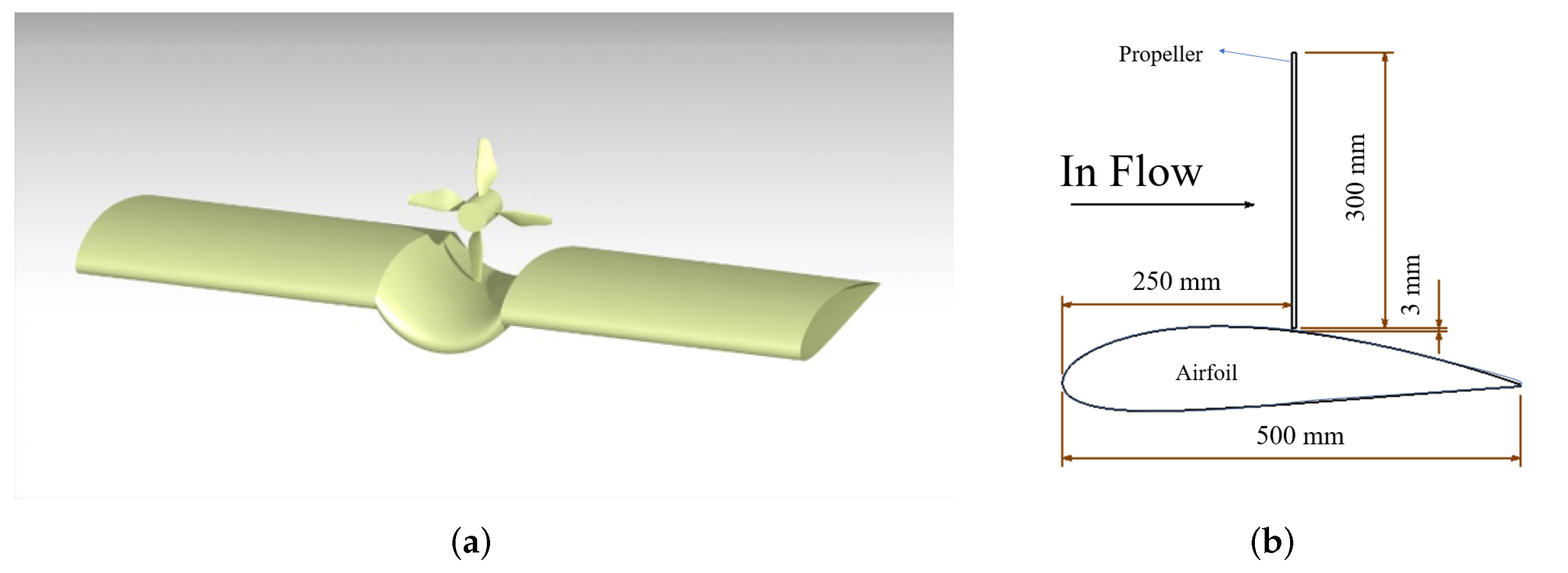
2. Numerical Methods Validation

2.1. Flow Solver

In this paper, ANSYS CFD package Fluent version 18.2 was used in the current simulations. To assess the accuracy and reliability of the numerical methods, a ducted propeller in the NASA D-995 report (shown as Figure 2a) was analyzed and validated against experimental data [24].
The compressible RANS equations were discretized by the cell-center finite volume method. Turbulence effects were considered by using two equations Shear Stress Transport ( k ω SST) model with low-Reynold-number correction. For the time integration, the lower-upper symmetric Gauss–Seidel (LU-SGS) implicit method was adopted. Free-stream conditions were the pressure-farfield condition. Parallel processing was achieved by domain decomposition of the computational mesh and Message Passing Interface (MPI). Computational meshes were generated by using ANSYS ICEM.
For propeller rotation simulation, the Sliding Mesh (SLM) method has been widely used and is known to yield realistic results in terms of the unsteady flow around propellers, but it would require a prohibitively large computational cost for shape design applications. The Multiple Reference Frame (MRF) method is a quasi-steady simulation for propellers that do not rotate blades. In this method, the reference frame is transferred to simulation the rotation of blades, so that it can save the computational cost. However, the MRF approach still requires detailed grids for blades leading to a greater computational cost than the Momentum Source Method (MSM) [25]. The MSM approach uses a thin disc to model the propeller without the mesh detail for blades, which is beneficial for saving computational cost in multi-propeller simulation. In the disc, flow-field parameters are obtained by User Define Function (UDF), such as the three components of flow velocity, coordinate and volume of a cell. Those parameters are used as the input of the Blade Element Theory (BET) [26]. The local angle of attack and vector of velocity are calculated with the obtained flow-field parameters. The thrust and torque at a cell can be calculated by BET for given propeller rotation speed, chord, twist angle, and airfoil database. Then, the three components of momentum increments caused by propeller can be calculated and used as the momentum source terms in Cell Zone Condition. By this method, the propeller performance at given rotation speed coupling with nonuniform flow fields can be analyzed and then feeds back to the flow field.
In this part, the above three methods are validated and compared. The MSM approach had about 2212 million structured grids (shown as Figure 2b). The multi-block structured–unstructured hybrid grids (shown as Figure 2c) with data-exchange interfaces were used to simulate the integration of rotational blades and stationary duct in MRF and SLM. It was comprised of two computational domains: one was for the stationary region with about 0.65 million structured grids; the other was for rotational region around the inside blades. In the SLM method, blades rotated 2 in one time-step.
To assess the grid-independence of the numerical methods, two mesh sizes of the rotational region were used in MRF: the mesh with 2.55 million unstructured girds was named MRF-1, and the mesh with 0.97 million unstructured girds was named MRF-2. Only the second mesh size was used in SLM. A case with the second mesh using the Spalart–Allmaras (SA) turbulence model was also simulated for comparison, where the propeller was modeled by MRF. This case was named as MRF-SA. In all cases, the height of the first layer of grid ensures that the y+ value is less than 1.0, with local refinement around blades, lip, and trailing edge.
The numerical simulations were performed at the same flow condition as in the wind tunnel testing [24], which was set to be: rotation rate n = 8000 r/min, advance ratio J = 0.032 , income flow velocity V = 1626 m/s, propeller diameter D p r o p = 15 in. Three angles of attack, α d u c t = 50 , α d u c t = 70 , and α d u c t = 90 , were simulated. The disc loading was about 1580 N/m 2 .

2.2. Results

Table 1 represented the comparison of blades thrust coefficients ( C T p ) and the ratio of blade thrust to total thrust ( T P / T 0 ) at different angles of attack ( α d u c t ) between experimental data and numerical results.
Notice that the inflow speed was a very low value ( V = 1.626 m/s) and far less than the propeller induced velocity (about 25 m/s), so the angle of attack had little effect on performance. Results illustrated that a relative error within 10% compared to the experimental data can be achieved for all the cases, and the difference between each case was less than 3%. Most important of all, thrust ratio ( T P / T 0 ) results showed good agreement with experimental data with a relative error within 2% (except for the MRF-SA case), which indicated that all cases can simulate blade–surface interaction accurately. The MRF-SA case shows similar error levels compared to k ω S S T cases for C T p , but the T P / T 0 error of MRF-SA was slightly larger than other cases. Therefore, only k ω S S T turbulence model was choosen for the following simulation.
The error of CFD might come from the inconsistency of model geometry, such as the model support system, hub geometry, and structure of blade root. The thrust from MSM was slightly higher than in other cases, but MSM could significantly reduce computational time and cost (the computational time of MSM was only about 40% of MRF and 6% of SLM in this case), which was important in multi-propeller simulation.
Another consideration was that the propeller would not move in the MRF method, instead, the reference frame was transformed to simulate the flow motion around the propeller. Therefore, the flow field around the propeller rotated but not propeller. In this way, MRF was accurate enough for most axisymmetric cases, such as isolated propeller, ducted propeller, and even the tractor configuration. However, when it came to non-axisymmetric propeller–wing integration such as over-the-wing propeller configuration, the MRF results were suspicious, which has been discussed in previous work [27]. Therefore, in the following section, only MSM and SLM are used to simulate the channel wing propeller integration.

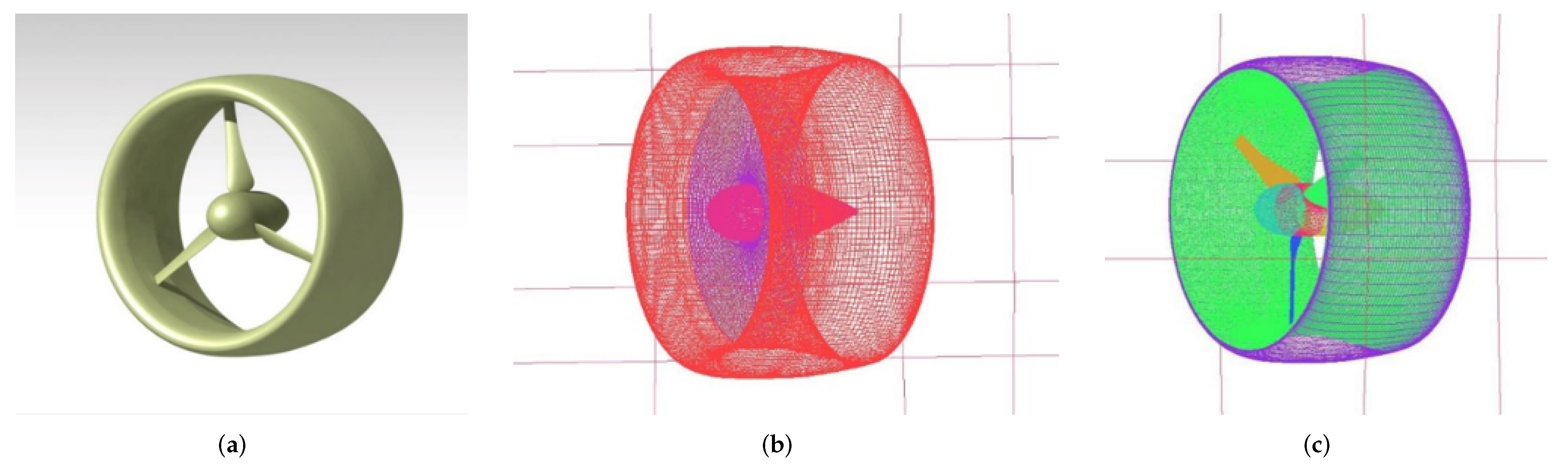
3. The Single-Propeller Channel Wing Integration

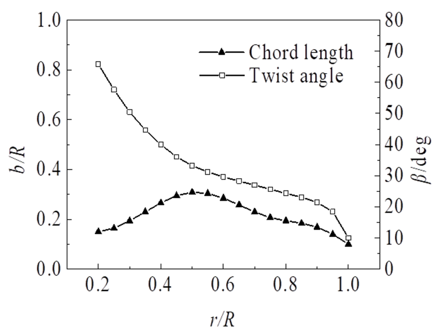
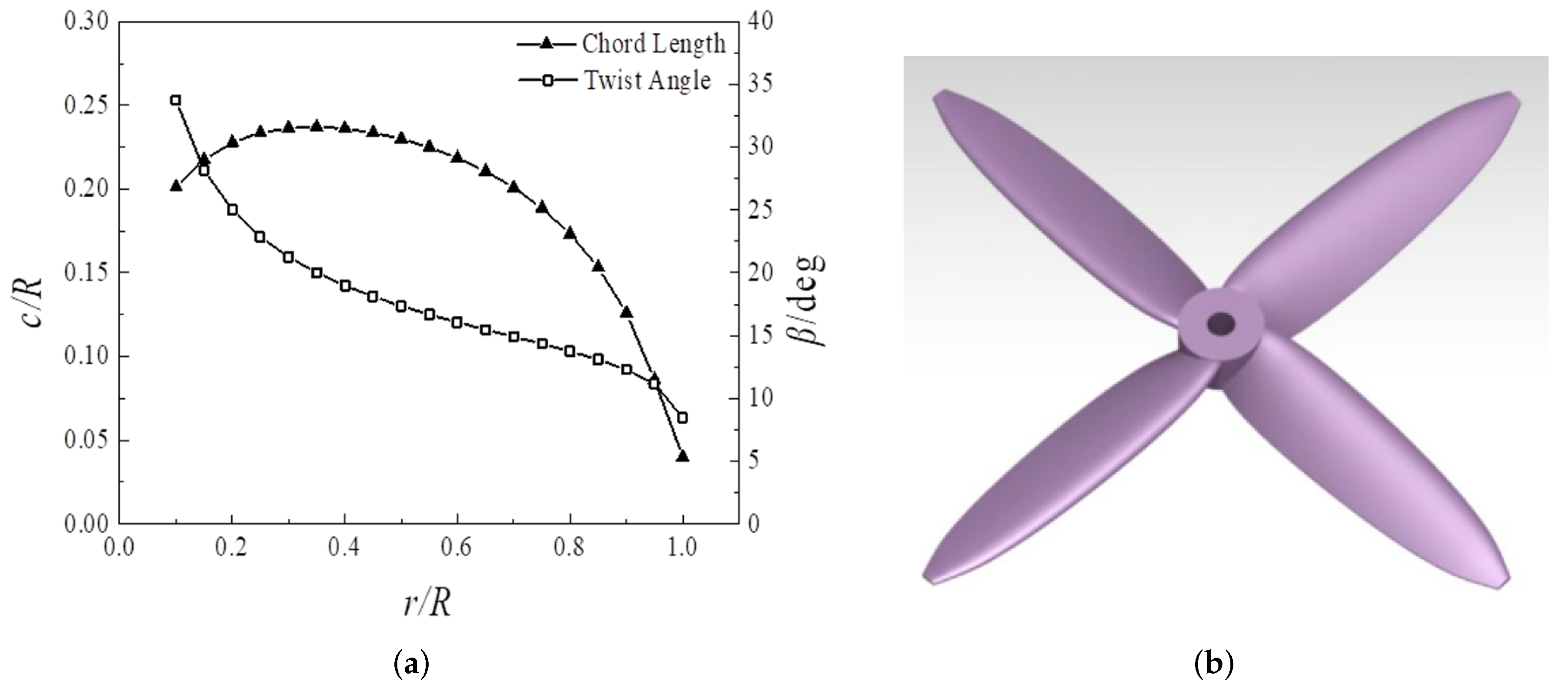
3.1. Model and Methods

The configuration of single-channel propeller–wing integration was shown in Figure 3. The wingspan was l = 1.52 m, wing area S = 0.76 m 2 , wing chord c = 0.5 m, and the propeller was located above the wing at 0.5 c , surrounded 120 by the channel wing. Hongbo Wang [8,9] and Marcus [10] have studied the effect of the position of the propeller, so this paper will not focus on the effect of the position of the propeller. To study the interaction between the propeller and the wing, ensure that the propeller and the wing have sufficient interference space, and the flow field before and after the propeller can develop with the coupling of the wing, in this paper, it was decided that the propeller would be placed at 0.5 c of the wing.
A four-blade propeller was used located above the half chord length of the channel wing with a narrow gap between propeller and wing. The airfoil of blades was Clark Y. The propeller was designed to provide a thrust larger than 100 N during VTOL stage, with an acceptable cruise efficiency (about 70%) at 40 m/s. The diameter D p r o p = 0.3 m, and tip Mach number is less than 0.55. However, the propeller design process is not the focus of this paper. The chord b and twist angle β are shown in Figure 4.
Two different configurations were compared (shown as Figure 5), and the interaction between propeller and airfoil will be discussed in the next section. The two airfoils were denoted as Config-1 and Config-2, respectively. For more details of the airfoil, please refer to previous work published in reference [27].
In this section, 3D RANS equations were solved coupled with the k ω SST turbulence model. Both MSM and SLM were used in this part to ensure the reliability of the simulation, keeping the grid type consistent with Section 2. Symmetrical boundary conditions are adopted at the wingtip face to eliminate the interference of three-dimensional effect of wingtip vortex, and to reduce the size of mesh. The pressure-farfield condition was used in the far-field. The MSM approach had about 1.5 million structured grids, while the SLM approach had about 1.9 million structured–unstructured hybrid grids. For the S/VTOL stage, the flow condition was set to be: rotation rate n = 11 , 500 r/min, income flow velocity V = 1 m/s, altitude H = 0 m. For the study of speed and disc loading, only V and n were changed, respectively.

3.2. Results

The performance of the channel wings using Config-1 and Config-2 airfoil, as well as the isolated propeller, were each analyzed. The results of the simulation are shown in Table 2. Note that the speed was very small at the S/VTOL stage (compared with the propeller slipstream velocity), so the inflow angle of attack did not play an important role. Due to the singularity at low freestream speed, nondimensional parameters need to be redefined.
In general, dimensionless coefficients such as C L and C D may be of a large value when V 0 m/s because of the singularity of the definition. In this paper, the propeller produces remarkable flow, so that there is still significant artificial flow when V 0 m/s. Therefore, to take the propeller-induced flow into account, powered lift coefficient C L p and drag coefficient C D p were defined as
C L p = L 1 2 ρ ( V + V l l ) 2 S = L 1 2 ρ V 2 ( 1 + a l l ) 2 S
C D p = D 1 2 ρ ( V + V l l ) 2 S = D 1 2 ρ V 2 ( 1 + a l l ) 2 S
where l / l was the ratio of the width affected by propulsion to the wingspan (namely, it was the ratio of the propeller diameter to the wingspan N p D p r o p / l for distributed propeller); a is defined as the ratio of increment velocity V to V at propeller disc [28]
a = V V = 1 + T / A 1 / 2 ρ V 2 1 2
By the definition of powered lift and drag coefficients, the artificial flow field is coupled with the free flow field. Although V is still in the denominator, a is also in the denominator. When V 0 , a , while V is a finite value (generated by propeller). Mathematically, there is no singularity about V here. Therefore, it could be used at both low freestream speed and high freestream speed.
Results indicated the good consistency between MSM and SLM. In 3D configuration, the lift of the Config-1 airfoil was 23% higher than Config-2, while the wing drag for both had a negative value. Compared with the isolated propeller, the thrust of the propeller in the channel wing was almost unchanged (slightly decreased). Caused by the negative drag of the wing, the net thrust of the propeller and wing were higher than the isolated propeller at given rotate speed. Without the propeller, the lift drag ratio of Config-1 is significantly lower than that of Config-1. However, when the propeller works, the propeller-induced lift of Config-1 is higher than that of Config-2, and the resultant force of Config-1 is also greater.
Performance results indicated that the airfoil shape played an important role in the interaction between propeller and channel wing. To study the mechanism of propeller–wing interference, the pressure coefficient distribution, pressure contours at the wing symmetry plane, and velocity contours in the wake are shown in Figure 6, Figure 7 and Figure 8, respectively. The dimensionless C p is defined as
C p = p p 1 2 ρ V 2 ( 1 + a ) 2
The comparison between MSM and SLM results indicates that MSM was able to simulate the propeller–wing interaction accurately for the channel wing. The tendency and distribution of pressure simulated by MSM were quite consistent with SLM. The data and figure reported here suggest that MSM was a creditable substitute for SLM to save computing time in simulating propeller–wing interaction of channel wing. Therefore, only MSM was used in the following section.
Compared with the Config-2 model, the high-pressure area of Config-1 wing was reduced to a narrow area behind the propeller, and a secondary peak of suction could be found, while the suction peak in front of the propeller also increased. This was because the Config-1 airfoil had greater curvature before and after the propeller disc, which led to greater flow deflection [17,18]. Therefore, the larger airfoil camber can provide larger lift. However, the camber of airfoil should not be too large, otherwise the cruise performance will be reduced. There needs to be a trade-off. The force gains in channel wing may come from the reduction of propeller-induced loss, similar to a ducted propeller. Therefore, the maximum gains of channel wing may not exceed that of the lip in ducted propeller.
It was noteworthy that the velocity contour in Figure 7 and Figure 8 was time-averaged. Therefore, the non-uniform distribution was not caused by the asynchronous. Instead, the unsteady effect was not significant for the wake. The non-uniform distribution revealed the distinct interference between propellers and wing. Figure 7 showed a significant asymmetric pressure distribution behind the propeller, which was the effect of the rotational slipstream (the rotation direction of the propeller was -x axis). However, because of the corner of the channel, there was a distinct pressure boundary of the channel that may help channel wing to maintain quasi-2D features.
The streamlines showed in Figure 7 presented a separation flow at the gap between propeller and channel wing. A vortex also appeared to the left of propeller. It is not a separation vortex, but an attached spanwise vortex. The spanwise vortex is the result of the coupling of gap separation, swirl effect, and the suction effect of the propeller. Note that there is high-speed flow and low-speed flow in the flow field. Although the streamline diagram does not show obvious separation flow, it does not mean that high-speed flow can always attach. In fact, the wake contours (Figure 8) show that the high-speed flow curls and is separated from the wing surface. The separation area of the high-speed flow is filled by the low-speed flow, so the streamline diagram does not show the separated flow.
The velocity contours in the propeller wakes shown in Figure 8 present a distort-and-dissipate effect. This will be discussed in detail in Section 4.2. Note that the wake shapes presented in Figure 8 are time-averaged, but the unsteady effect of the propeller wake is not significant. The velocity wake of the propeller at different step times is almost the same. Again, the wakes from MSM and SLM showed good consistency.

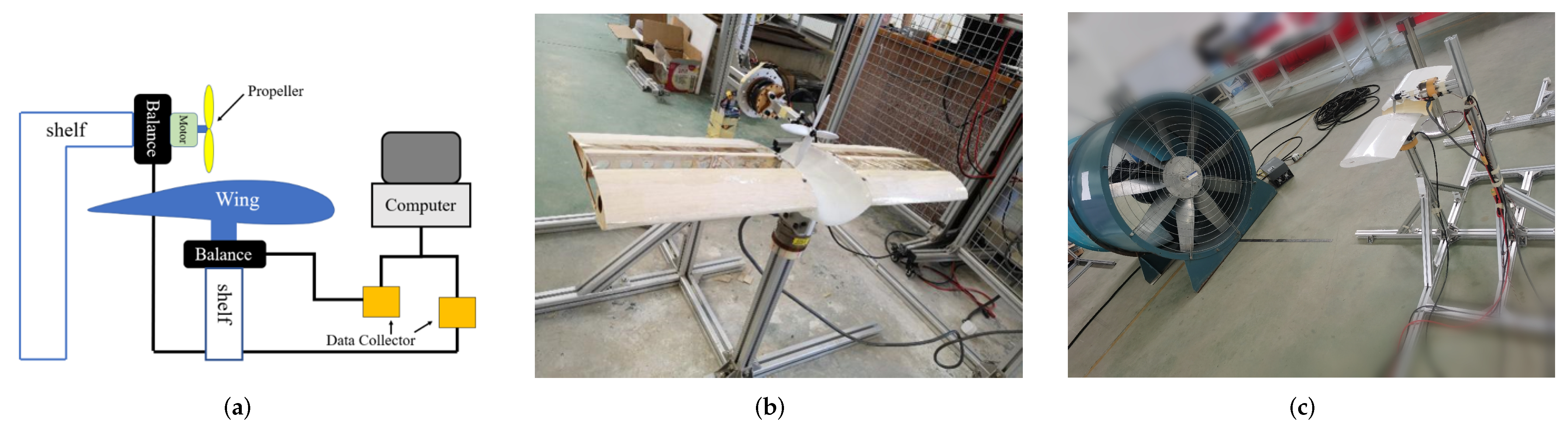
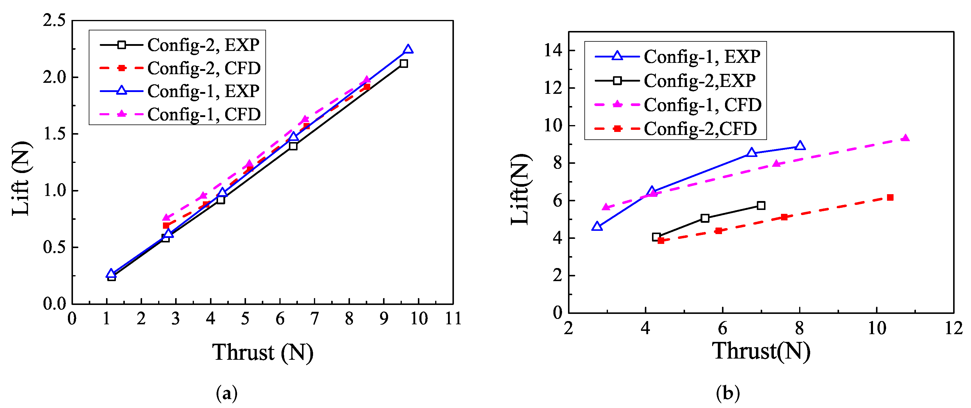
3.3. Ground Test of a Scaled Model

To preliminarily verify the effect of single-channel wing, a low-cost ground test was performed with an open wind tunnel.
The tested models were 0.5 scaled models of the single-channel propeller–wing integration with Config-2 and Config-1 airfoil, respectively, which are discussed in Section 3.1 and Section 3.2. The two wing models with Config-2 and Config-1 airfoil corresponded to the model in Section 3.1, but the propeller model was changed and is shown in Figure 9. The propeller had 4 blades with Clark-Y airfoil, and its diameter was 0.15 m. Due to the safety problem caused by vibration, the gap between propeller and wing was increased to about 7.5 mm. The numerical methods and mesh corresponded to those in Section 3.1.
The static test was conducted at an altitude of about 400 m and velocity of 0 m/s. The low-speed test was conducted in a simple open wind tunnel (as shown in Figure 10c) with a wind speed of 5 m/s near the tested wing. Two six-component balances were used to measure the force and torque of the propeller and wing, respectively. The data collectors were directly connected with the six-component balance and the computer. The motor and wing were fixed on the six-component balance, which is shown in Figure 10.
The results of the static test and numerical methods are compared in Figure 11a, which showed the variation of lift with propeller thrust. The results of numerical methods were in good agreement with the experimental results, and the lift increment from Config-2 to Config-1 airfoil was simulated correctly. Only a slight overestimation occurred at low thrust condition (caused by relatively larger disturbance). However, the induction rate was only about 0.22. The increase of the gap between propeller and wing caused a dramatic decrease in the wing lift compared with the model in Section 3.2.
The low-speed test shows a larger CFD error than the static test, as presented in Figure 11b. However, the low-speed test confirms that the difference between two airfoil simulated by CFD is credible, while the value from CFD may be underpredicted.
The comparison between test and simulation indicated that the numerical methods were reliable in simulating the coupled aerodynamic features of channel wing, and the airfoil design strongly affected the channel wing performance.

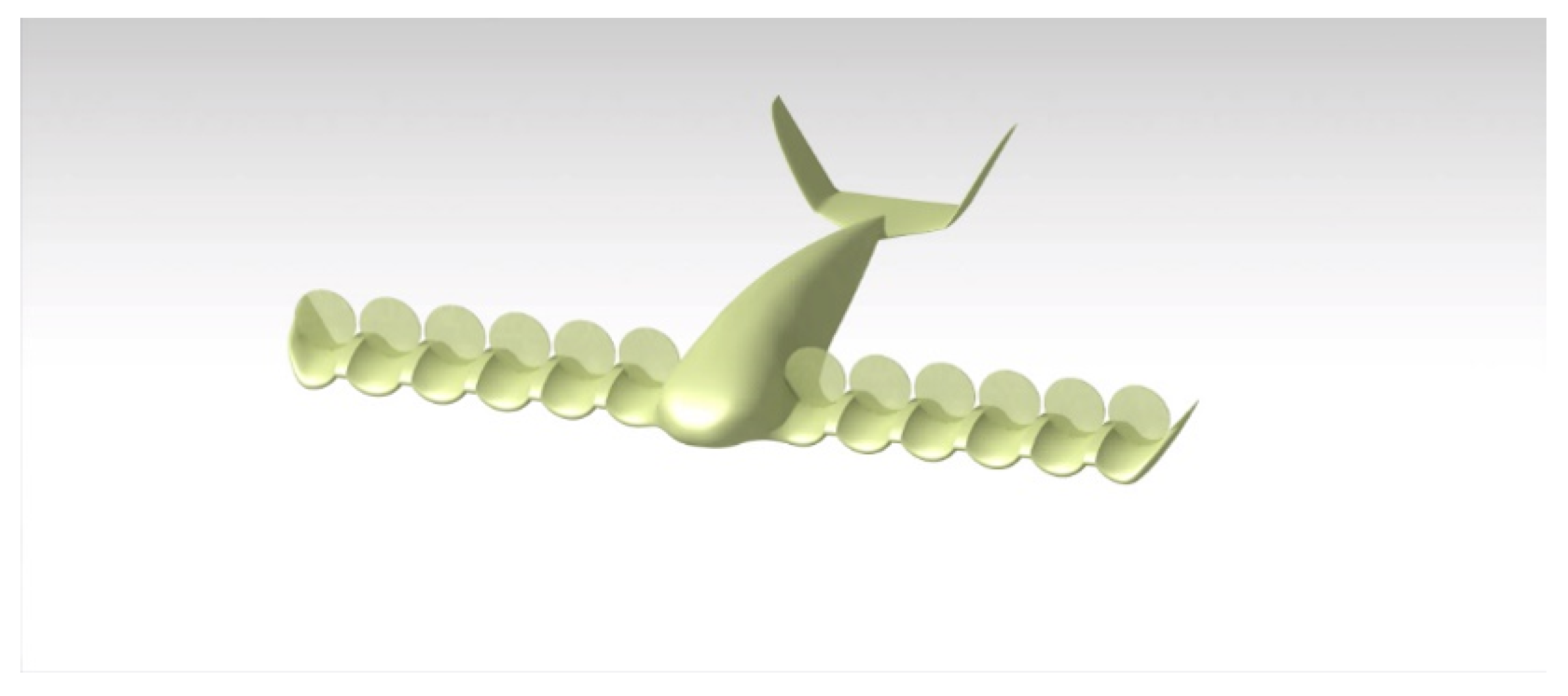
4. The Multi-Propeller Channel Wing Integration

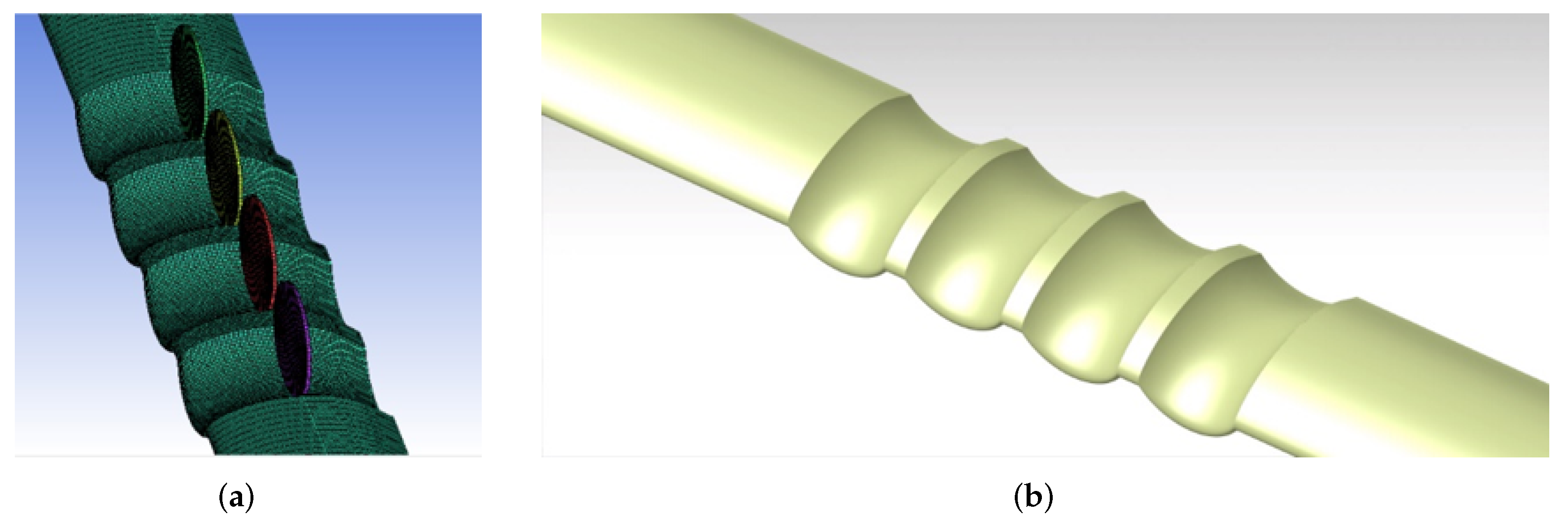
4.1. Model and Methods

As discussed above, in OTWP configuration, wing and propeller interact with each other. However, interactions between propellers or channels are also important in the distributed multi-propeller concept. In this section, a four-propeller channel wing with Config-1 airfoil is studied. Figure 12 presents the mesh and geometries of a four-propeller channel wing integration. The channel width, chord, propeller diameter, and location were the same as those discussed in Section 3.1. The wingspan was l = 2.88 m, the wing area was S = 1.44 m 2 , and there was a narrow gap between two propellers.
To find the mechanics of interaction between propellers, three propeller rotating directions were studied, which are shown in Figure 13. The rotating direction that was along the x-axis was named ‘positive’ (P), another direction was named ‘negative’ (N), and the four propellers were numbered according to the positive direction of the z-axis.
The simulation methods were maintained the same as Section 3.1, with about 5.2 million structured grids domain. RANS equations were solved coupled with the k ω SST turbulence model. Only MSM was used to reduce the computational cost. Additionally, for the S/VTOL stage, the flow condition was set to be: n = 11 , 500 r/min, V = 1 m/s, H = 0 m. Furthermore, for the low-speed condition, the flow condition was set to be: n = 11 , 500 r/min, V = 20 m/s, H = 0 m, the total thrust was about 340 N.

4.2. Results and Discussion

4.2.1. The S/VTOL Stage

Due to the difference of dimensionless methods between propeller and wing parameters (such as C T p = T p / ( ρ ( n / 60 ) 2 D p r o p 4 ) and C L = L / ( 1 / 2 ρ V 2 S ) ), it is difficult to identify the force relationship of the propeller and wing, such as the wing lift induced by unit thrust. To better understand the relationship between the components, the performance of the propeller–wing integration in Table 3 is not dimensionless. The induction rate is the ratio of the wing lift to the thrust of propeller. The power loading P L is the ratio of the resultant force (propeller and wing) to power P P .
Compared with the single-propeller channel wing which was discussed in Section 3.2, results showed that the multi-propeller channel wing achieved a lager induced rate, leading to higher lift and lower drag induced by unit thrust. This result was beneficial to the practice of distributed multi-propeller channel wing. Meanwhile, the rotation direction would affect the performance of the channel wing significantly. The PNPN had the highest induced force while the force of NPNP was lowest.
The increase of the induced force in a multi-propeller configuration might result from the significant interference between propellers. To find the interaction between propellers and wing, the flow field of the isolated propeller, single-propeller channel wing, and multi-propeller channel wing were analyzed. To show the development of the propeller wakes, the velocity contours are shown in Figure 14.
Several important interference behavior were discussed in the following paragraphs.

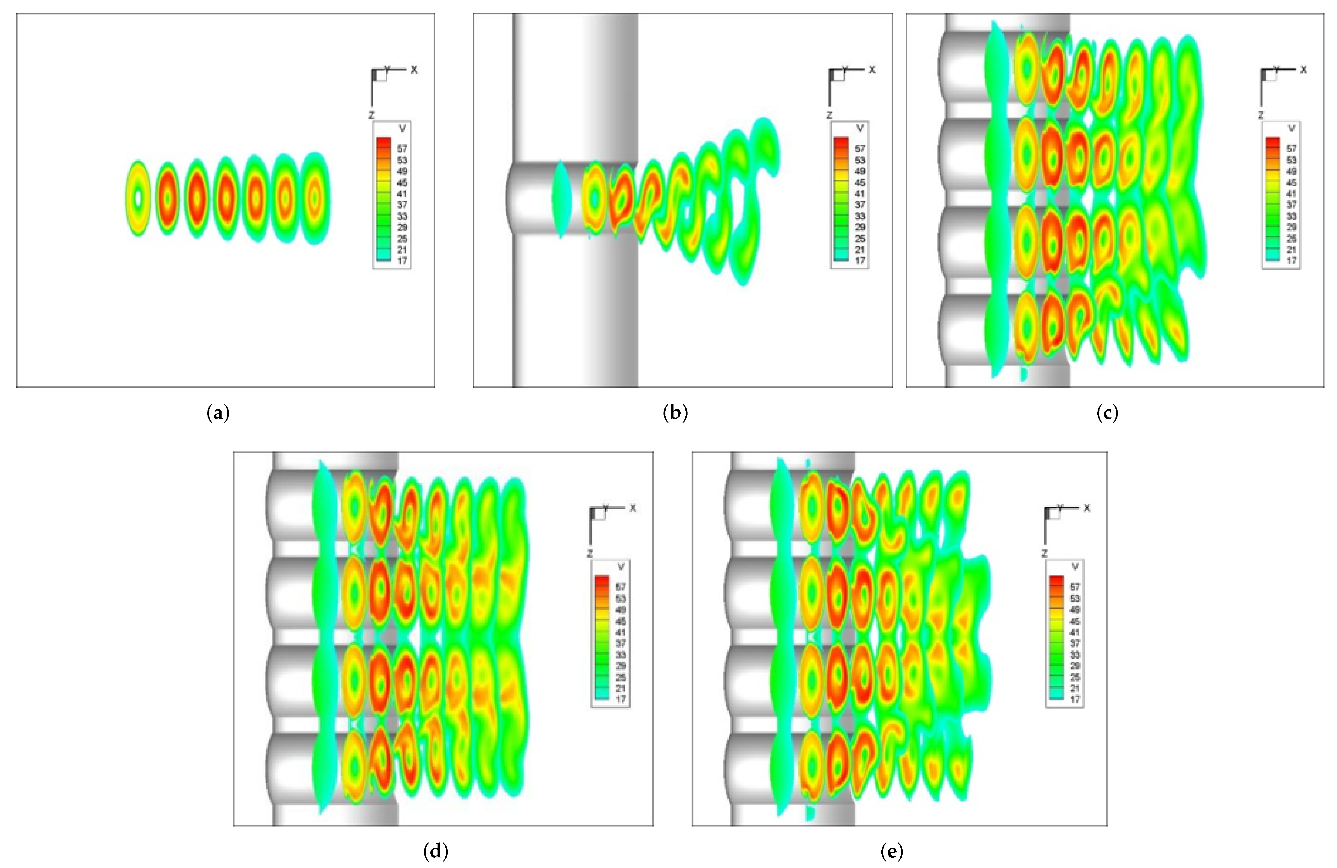
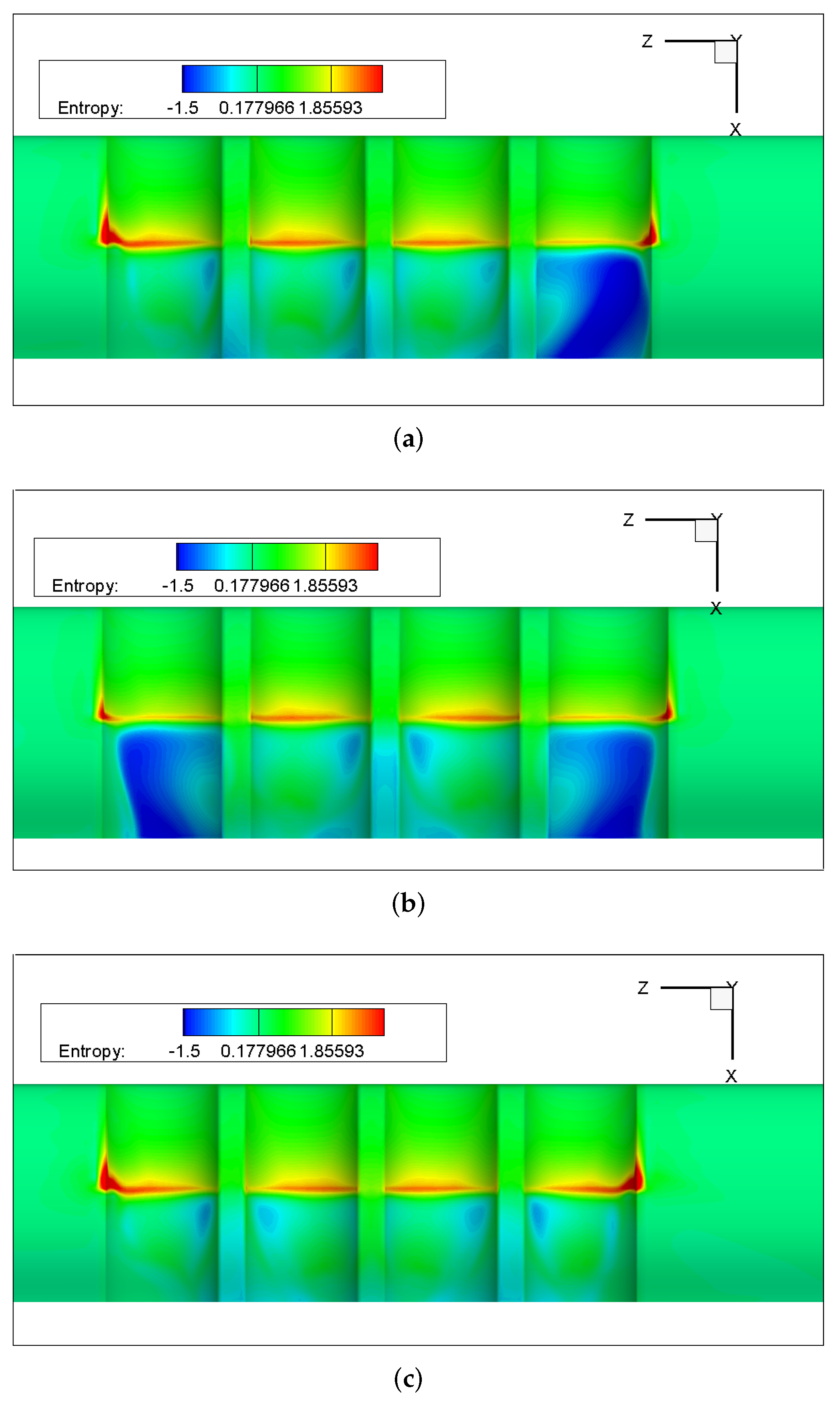
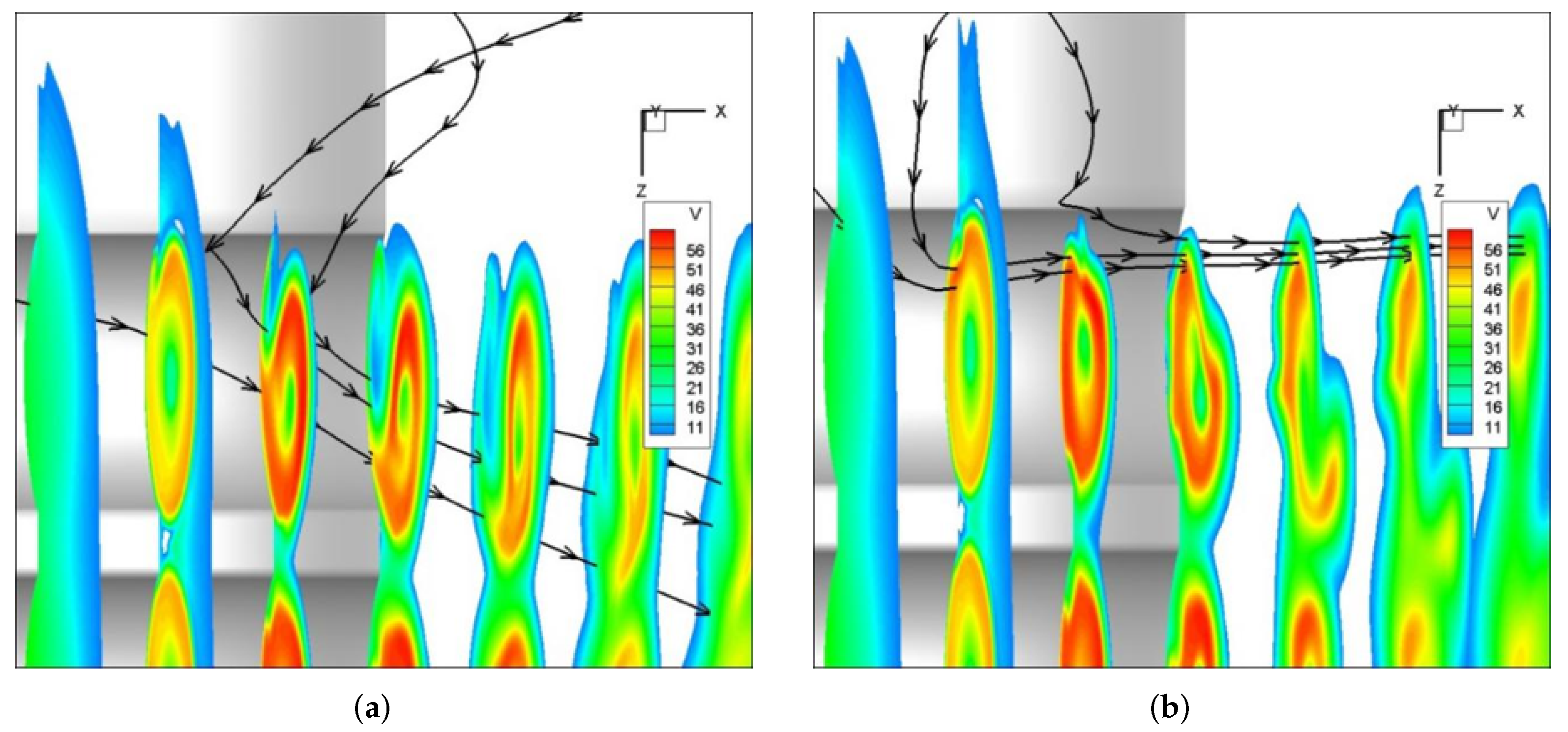
Wake Distortion and Dissipation

The most important interaction of wing and propeller was that the channel wing would change the wake of propeller. As shown in Figure 14a,b, the wake of the isolated propeller remained circular and extended backward, but the wake of the single-propeller channel wing was distorted and dissipated faster. The reason for this phenomenon might be the interaction between the wake’s swirl effect and the wing’s Coanda effect. The wake of propeller tended to stay attached to the convex wing surface and was flattened, while the swirl effect caused low-energy flow to be carried into the channel, which would disrupt the wake and dissipate it faster. Similar cases could be found from the outside two propeller wakes in Figure 14c–e.
The wake distortion and dissipation will affect the wing lift because the Coanda effect requires stable and attached high-speed flow. If the propeller wake distorted and dissipated behind the rotor, the low-momentum flow would be entrained in the channel, so the lift generated by the wing trailing edge would decrease. This could be proven by the pressure contour shown in Figure 15 and the lift distribution in Figure 16, which indicated that the lift loss region (red region) is always located at the wake distortion channel. For example, the wakes in the outside channels in Figure 15b are distorted and the high-speed flow cannot remain attached, so the lift loss is significant; whereas, the wakes in the outside channels in Figure 15c dissipated fast but it was not strongly distorted, and the high-speed flow remained attached, so the lift performance was better, but there was still a loss compared to the middle two channels. The pressure distribution of the wing in front of the propeller disk is similar, but the pressure distribution behind the propeller disk is different due to the different propeller wake. Therefore, the propeller wake near the channel has an important impact on the characteristics of the wing.
The entropy contours in Figure 17 also show a similar phenomenon. Note that the entropy E is computed in terms of the relevant ideal gas properties and the departure functions, with mean molecular weight M W (Kg/kmol):
E = E i d e a l E d e p a r t u r e / M W
Figure 17 shows a negative E in the channel with outboard-down rotation, which indicates the increase of entropy and drag loss. Therefore, NPNP has the most drag loss, while the drag loss of PNPN is the smallest. This can be confirmed by induction rate, power loading, and x-force in Table 3 (note that the power is different in Table 3).

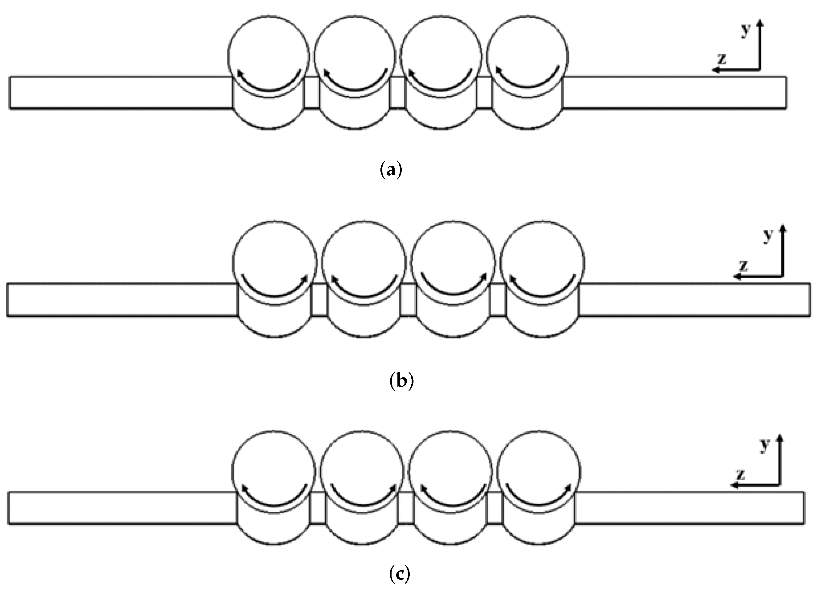
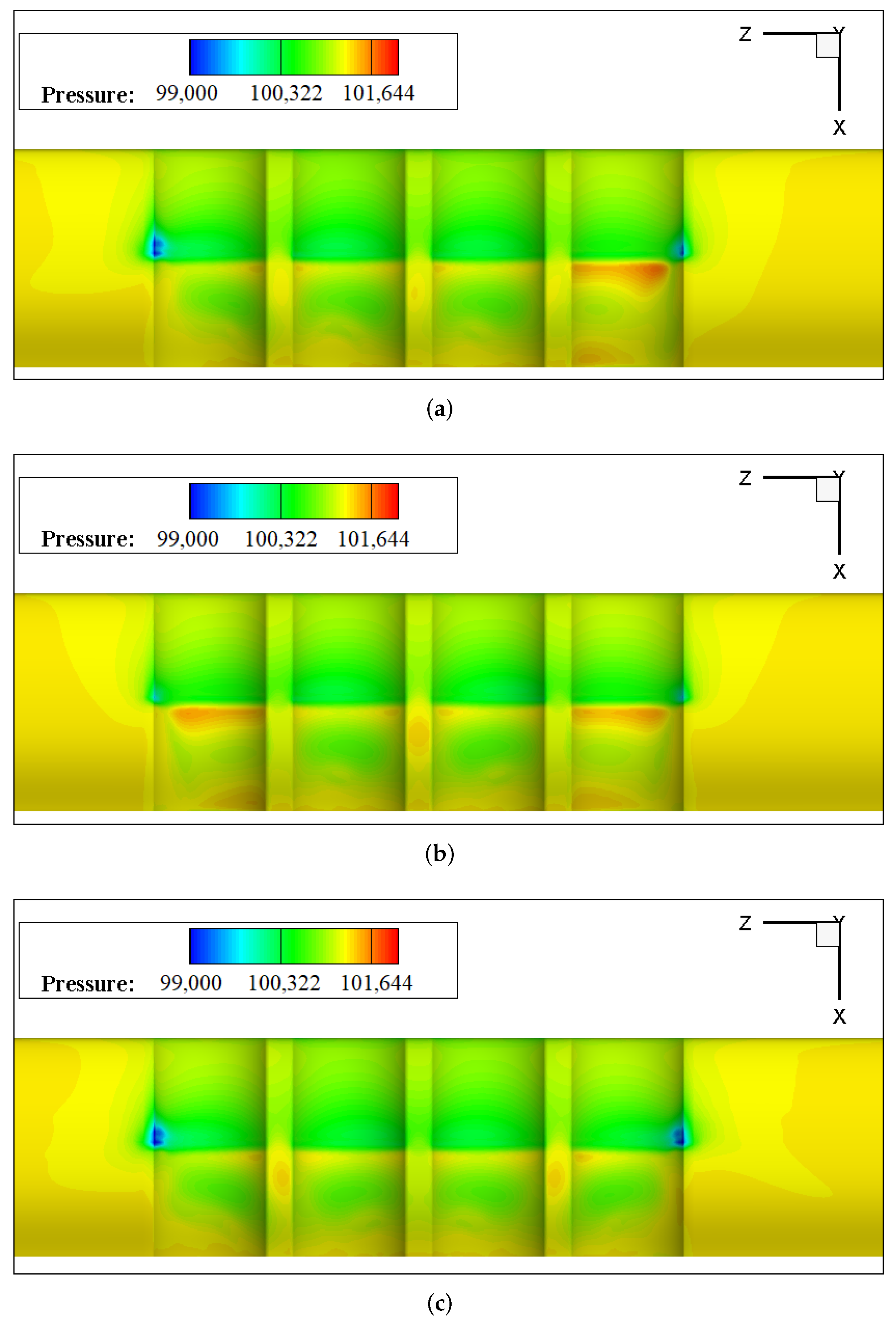
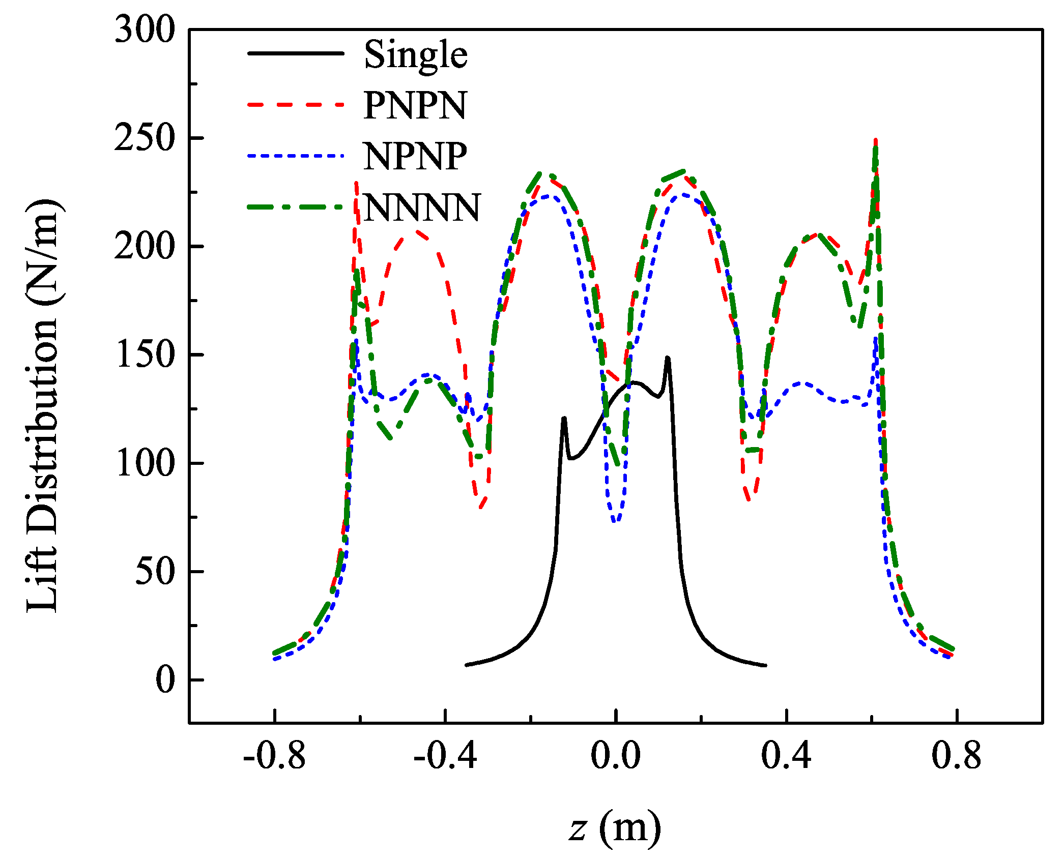
Interference between Adjacent Propellers

However, as shown in Figure 14c–e, the two wakes in the middle channels did not show notable distortion and fast dissipation, while only the swirl effect was remarkable. This might have been caused by the resistance between the two propellers which prevented the rapid distortion and dissipation of wakes. In this way, the middle two wakes could remain circular. By comparison, the outside two wakes dissipated fast and were obviously distorted. In addition, the middle two propellers provided more induced lift, which was shown in lift distribution (in Figure 16). It showed a very regular and smooth distribution in the middle of the wing, while the distributions outside the wing were more complicated.
In the middle gap of two propellers, the rotation direction also played an important role. Compared with the rotation in the same direction of NNNN, middle-up rotation obtained more lift. On the contrary, middle-down rotation obtained lower lift, which could be found in NPNP or PNPN. However, its contribution to the lift difference was small.
In addition, the induced lift outside the channel did not disappear rapidly, but extended outward and disappeared after a certain distance, as shown in Figure 16. In this section, the induced lift disappeared at about 0.66 D p r o p outside the channel.

Entrainment of Low-Momentum Flow

As shown in Figure 16, although the outside propeller lost the adjacent propeller effect, both the outside channel of PNPN and the right-side channel of NNNN obtained higher induced lift than other cases (outside channels) and the single-propeller case. As mentioned above, the reason why the outside channels lost induced lift was that the swirling wake sweeps outer low-energy flow into the channel. Therefore, the rotating direction was a key point which might impact on the channel wing performance. When the outside propeller rotation was outboard-down, the low-energy flow came into the channel and disturbed the slipstream of the propellers. In contrast, the outboard-up rotation tended to prevent the intrusion of outer flow, but the wakes would still be slightly disturbed and gradually distorted, as shown in Figure 18.
As noted above, the lift loss region is always located at the wake distortion channel. Therefore, the intrusion effect was the main reason for the lift difference of NNNN, NPNP, and PNPN, which suggests that the outside propeller should have outboard-up rotation to obtain a larger induced force.

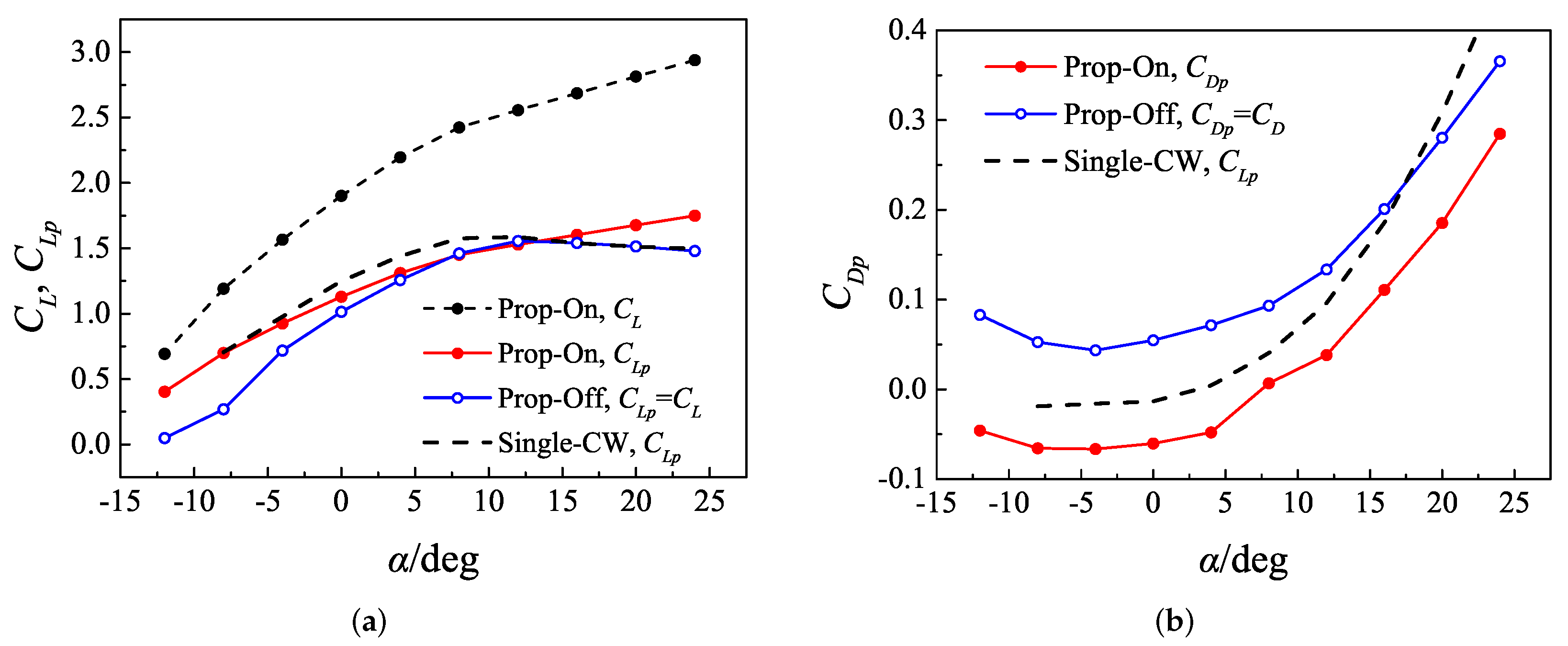
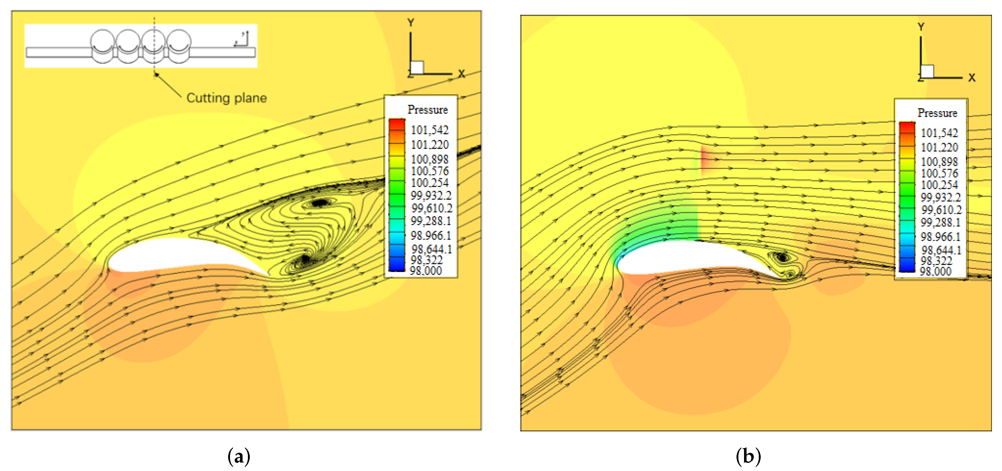
4.2.2. The Low-Speed Flight

As mentioned in the previous sections, the freestream velocity was set to be of a small value (compared with the propeller-induced velocity), so that the influence of the angle of attack was rather small. To study the channel wing performance at different angles of attack, the channel wing performance was analyzed and the curves versus angle of attack were shown in Figure 19. Compared with the single-channel wing, the multi-channel wing has more lift gain and drag reduction. This is mainly because the multi-channel wing has a higher ratio of propeller diameter to wing length than the single-channel wing. As discussed above, the performance of the multi-channel wing is better than single-channel wing, benefiting from the interference between channels. The flow regions without propeller slipstream will separate, while the separation in the propeller slipstream will be delayed. Therefore, the distributed propeller layout is more conducive to delaying the separation than the conventional propeller layout.
The drag of the prop-on channel wing dropped sharply compared with the clean wing. Meanwhile, the lift coefficient increased dramatically. Therefore, the channel wing had a significant effect on increasing lift and reducing drag. As shown in Figure 19, the channel wing had a larger stall angle of attack than the clean wing. In fact, the channel wing also suffered flow separation, but the separated area was smaller than that of the clean wing, benefiting from the energy input from the propeller. This is illustrated in Figure 20.
Figure 20 presents the pressure contours and stream traces of the cutting plane at x = 0.15 m with α = 24 . The clean wing experienced severe separation before the half chord of the wing, while the flow in channel wing is separated at the trailing edge. The propeller-coupled effect could greatly improve the maximum lift coefficient and safety during takeoff and landing.

5. Conclusions

Interaction effects on the channel wing were investigated by applying numerical simulation with the Momentum source method. Isolated propeller, single-channel propeller–wing integration, and multi-propeller channel wing integration were analyzed to find the mechanism of propeller–wing interference on the distributed propeller channel wing.
Numerical methods were compared and validated with the experiment data of ducted propeller in Section 2 and scaled channel wing in Section 3.3, which indicated that the Momentum Source Method in this paper was reliable for propeller–wing integration simulation.
Investigation into the single-channel propeller–wing integration showed that the airfoil with larger curvature under the propeller coupling increased lift by 23% compared with a normal airfoil. This results showed a potential of channel wing for high-efficiency S/VTOL. However, larger camber results in higher drag at cruise, which requires a trade-off.
We also found several important interaction effects. Under the interaction of channel wing, the propeller’s wakes might distort and dissipate faster than the isolated propeller, so that the propeller’s wake could not remain circular. This phenomenon might be caused by the coupling of the wake’s swirl effect. The swirl of the wake swept the low energy flow into the channel and disturbed the wake, while the slipstream tended to attach to the wing and was flattened. Therefore, the propeller slipstream in the channel wing was very different from the isolated propeller.
Studies on the multi-propeller channel wing indicated that the interference between channels were non-negligible. The middle channels showed different behaviors with outside channels. The middle propellers’ wakes could remain circular, and middle channels provided more lift than outside channels. Therefore, multi-propeller configuration showed a higher induced rate than the single-propeller channel wing. However, outside channels were more complicated and were affected by the propeller rotation direction. As a result of the entrainment of low-momentum flow in outboard-down cases, outboard-up rotation might help to avoid lift loss. In this way, the performance of multi-propeller channel wing integration could be improved. This conclusion might be beneficial to the practice of distributed multi-propeller channel wing.
In addition, the channel wing could greatly improve stall characteristics, and provide a larger available lift coefficient at low speed. This could be regarded as an automatic flap without mechanical deflection. The lower the flight speed, the higher the lift increment.
The channel wing has remarkable aerodynamic advantages, such as high efficiency for S/VTOL and low-speed cruise. The purpose of this paper is to highlight more possibilities of propeller–wing layout and related coupling effects, and to provide some ideas for future aircraft design. However, the research in this paper is only preliminary analysis, and we need to perform sufficient experimental verification, especially accurate wind tunnel test verification and research. The aerodynamic interactions in channel wing are complex and significant, and they deserve more attention. Meanwhile, the wavy wing may bring structural complexity, which requires further study and multidisciplinary cooperation.

Author Contributions

Conceptualization, J.Z. and Z.F.; methodology, Z.F.; validation, Z.F.; writing—original draft preparation, Z.F.; writing—review and editing, J.Z., M.C. and G.W.; supervision, J.Z.; project administration, G.W.; funding acquisition, J.Z. All authors have read and agreed to the published version of the manuscript.

Funding

This research was funded by the Key Basic Research Program for Base Strengthening Project of China (grant number 2020-JCJQ-ZD-076-00).

Informed Consent Statement

Informed consent was obtained from all subjects involved in the study. Written informed consent has been obtained from the patient(s) to publish this paper.

Data Availability Statement

Not applicable.

Conflicts of Interest

The authors declare no conflict of interest.

Nomenclature

The following nomenclature are used in this manuscript:
nrotation rate, r/min
V freestream velocity, m/s
Haltitude, m
ρ air density, kg/m 3
D p r o p diameter of propeller, m
Jadvance ratio, J = V / ( n D )
α d u c t angle of attack of duct, degree
Klift-to-drag ratio
D L disc loading, N/m 2
C T p thrust coefficient of propeller, C T p = T p / ( ρ ( n / 60 ) 2 D p r o p 4 )
C Q torque coefficient of propeller, C Q = Q / ( ρ ( n / 60 ) 2 D p r o p 5 )
T P blade thrust, N
T 0 total thrust including blade and lip of duct, N
lwingspan, m
Swing area, m 2
cwing chord, m
β blade twist angle, degree
rradius location of blade section, m
Rradius of propeller, m
N P number of propeller in distributed-propeller wing
V propeller induced velocity, m/s
aratio of V to V
C L p powered lift coefficient, C L p = L / { 1 / 2 ρ V 2 ( 1 + a D p r o p / l ) 2 S }
C D p powered drag coefficient, C D p = D / { 1 / 2 ρ V 2 ( 1 + a D p r o p / l ) 2 S }
ppressure, pa
C p pressure coefficient, C p = ( p p ) / ( 1 / 2 ρ V 2 ( 1 + a ) 2 )
P P Shaft power of the propeller, W
C P power coefficient of propeller, C P = P P / ( ρ ( n / 60 ) 3 D p r o p 5 )
δ deflect angle, degree
x , y , z reference frame
bblade chord, m
Subscripts
degdegree
configconfiguration
proppropeller
Abbreviations
OTWPOver-the-wing propeller
DEPDistributed electric propulsion
CFDComputational Fluid Dynamics
MRFMultiple Reference Frame
MSMMomentum Source Method
SLMThe method of sliding mesh
BETThe Blade Element Theory
CWChannel wing
S/VTOLShort/Vertical Take-Off and Landing

References

  1. Deere, K.A.; Viken, J.K.; Viken, J.K.; Viken, S.A.; Carter, M.B.; Cox, D.; Wiese, M.R.; Farr, N. Computational component build-up for the X-57 distributed electric propulsion aircraft. In Proceedings of the AIAA Aerospace Sciences Meeting, Kissimmee, FL, USA, 8–12 January 2018. [Google Scholar]
  2. Rothhaar, P.M.; Murphy, P.C.; Bacon, B.J.; Gregory, I.M.; Grauer, J.A.; Busan, R.C.; Croom, M.A. NASA langley distributed propulsion VTOL tilt-wing aircraft testing, modeling, simulation, control, and flight test development. In Proceedings of the AIAA AVIATION 2014 -14th AIAA Aviation Technology, Integration, and Operations Conference, Atlanta, GA, USA, 16 June 2014. [Google Scholar]
  3. Wang, K.; Zhou, Z.; Zhu, X.; Xu, X. Aerodynamic design of multi-propeller/wing integration at low Reynolds numbers. Aerosp. Sci. Technol. 2019, 84, 1–17. [Google Scholar] [CrossRef]
  4. Englar, R.J.; Campbell, B.A. Development of pneumatic channel wing powered-lift advanced super-STOL aircraft. In Proceedings of the 20th AIAA Applied Aerodynamics Conference, St. Louis, MO, USA, 24–26 June 2002. [Google Scholar]
  5. Muller, L.; Heinze, W.; Kozulovic, D.; Hepperle, M.; Radespiel, R. Aerodynamic installation effects of an over-The-wing propeller on a high-lift configuration. J. Aircr. 2014, 51, 249–258. [Google Scholar] [CrossRef]
  6. Muller, L.; Friedrichs, J.; Koulovi, D. Unsteady flow simulations of an over-the-wing propeller configuration. In Proceedings of the 50th AIAA/ASME/SAE/ASEE Joint Propulsion Conference 2014, Cleveland, OH, USA, 28 July 2014. [Google Scholar]
  7. Beck, S.C.; Muller, L.; Langer, S.C. Numerical assessment of the vibration control effects of porous liners on an over-the-wing propeller configuration. Ceas Aeronaut. J. 2016, 7, 275–286. [Google Scholar] [CrossRef]
  8. Wang, H.; Zhu, X.; Zhou, Z. Numerical simulation of the propeller/wing interactions at low reynolds number. In Proceedings of the 30th Congress of the International Council of the Aeronautical Sciences, Daejeon, Korea, 25 September 2016. [Google Scholar]
  9. Wang, H.; Zhu, X.; Zhou, Z.; Zhang, Y. New Configuration Design and Analysis for a Vertical Take-off/Hovering Solar Powered Aircraft. J. Northwestern Polytech. Univ. 2017, 35, 189–196. [Google Scholar]
  10. Marcus, E.A.P.; De Vries, R.; Kulkarni, A.R.; Veldhuis, L.L.M. Aerodynamic Investigation of an Over-The-Wing Propeller for Distributed Propulsion. In Proceedings of the AIAA Aerospace Sciences Meeting, Kissimmee, FL, USA, 8–12 January 2018. [Google Scholar]
  11. Schetz, J.A.; Hosder, S.; Dippold, V., III; Walker, J. Propulsion and Aerodynamic Performance Evaluation of Jet-Wing Distributed Propulsion. Aerosp. Sci. Technol. 2010, 14, 1–10. [Google Scholar] [CrossRef]
  12. Traub, L.W. Effect of a Pusher Propeller On a Delta Wing. Aerosp. Sci. Technol. 2016, 48, 115–121. [Google Scholar] [CrossRef]
  13. Yang, Y.; Zhou, T.; Sciacchitano, A.; Veldhuis, L.L.M.; Eitelberg, G. Experimental Investigation of the Impact of a Propeller On a Streamwise Impinging Vortex. Aerosp. Sci. Technol. 2017, 69, 582–594. [Google Scholar] [CrossRef]
  14. Alba, C.; Elham, A.; Veldhuis, L.L.M.; German, B.J. A Surrogate-Based Multi-Disciplinary Design Optimization Framework Exploiting Wing-Propeller Interaction. In Proceedings of the 18th AIAA/ISSMO Multidisciplinary Analysis and Optimization Conference, Denver, CO, USA, 5–9 June 2017. [Google Scholar]
  15. Ananda, G.K.; Selig, M.S.; Deters, R.W. Experiments of Propeller-Induced Flow Effects On a low-Reynolds-number Wing. AIAA J. 2018, 56, 3279–3294. [Google Scholar] [CrossRef] [Green Version]
  16. Guruswamy, G.P. Dynamic Aeroelasticity of Wings with Tip Propeller by Using Navier-Stokes Equations. AIAA J. 2019, 57, 3200–3205. [Google Scholar] [CrossRef]
  17. Cochrane, J.A.; Carros, R.J. Hybrid Upper Surface Blown Flap Propulsive-Lift Concept for the QSRLP. J. Aircr. 1976, 13, 855–860. [Google Scholar] [CrossRef]
  18. Harrison, N.A.; Vassberg, J.C.; DeHaan, M.A.; Gea, L. The Design and Test of a Swept Wing Upper Surface Blowing (USB) Concept. In Proceedings of the 51st AIAA Aerospace Sciences Meeting Including the New Horizons Forum and Aerospace Exposition 2013, Grapevine, TX, USA, 7–10 January 2013. [Google Scholar]
  19. Dragan, V. A Study of Conventional Upper Surface Blown Wing Configurations. Rev. Air Force Acad. 2012, 1, 9–12. [Google Scholar]
  20. Radespiel, R.; Kamruzzaman, M. Use of Upper Surface Blowing and Circulation Control for Gapless High-Lift Configurations. In Proceedings of the CEAS/KATnet Conference on Key Aerodynamics Technologies, Bremen, Germany, 20–22 June 2005. [Google Scholar]
  21. Keen, E.B.; Mason, W.H. A Conceptual Design Methodology for Predicting the Aerodynamics of Upper Surface Blowing On Airfoils and Wings. In Proceedings of the Collection of Technical Papers–AIAA Applied Aerodynamics Conference, Toronto, ON, Canada, 6 June 2005; pp. 1253–1267. [Google Scholar]
  22. Hill, G.A.; Kandil, O.A.; Hahn, A.S. Aerodynamic Investigations of an Advanced Over-The-Wing Nacelle Transport Aircraft Configuration. J. Aircr. 2009, 46, 25–35. [Google Scholar] [CrossRef]
  23. Dumitrache, A.; Frunzulica, F.; Preotu, O. Applications of the Coanda Effect in Aeronautics. In Proceedings of the 2018 9th International Conference on Mechanical and Aerospace Engineering, Budapest, Hungary, 10–13 July 2018; pp. 121–125. [Google Scholar]
  24. Kalman, J.; Grunwald, K.; Goodson, W. Aerodynamic Loads on an Isolated Shrouded-Propeller Configuration for Angels of Attack from −10° to 110°; NASA TN D-995; NASA: Washington, DC, USA, 1962. [Google Scholar]
  25. Zhenfeng, X. Numerical Approaches of Propeller Slipstream Simulations and Aerodynamic Interference Analysis. Ph.D. Thesis, Northwestern Polytechnical University, Xi’an China, 2015. [Google Scholar]
  26. Liu, P. Theory and Application of Airscrew; Beihang University Press: Beijing, China, 2008. [Google Scholar]
  27. Fan, Z.; Zhou, Z.; Zhu, X.; Guo, J. Coupled Aerodynamic Analysis and Airfoil Optimization Design for Over-Wing Propeller Configuration. Acta Aeronaut. Astronaut. Sin. 2019, 40, 73–87. [Google Scholar]
  28. Fan, Z.; Zhou, Z.; Zhu, X. A Design Method for Propeller with Arbitrary Circulation Distribution. J. Aerosp. Power 2019, 34, 434–441. [Google Scholar]
Figure 1. A model of the multi-propeller channel wing UAV.
Energies 15 05352 g001
Figure 2. The NASA D-995 ducted propeller. (a) The geometric model; (b) The mesh of MSM; (c) Hybrid mesh.
Energies 15 05352 g002
Figure 3. The model of the single-propeller channel wing integration. (a) Geometry of channel wing; (b) Section sketch at the wing symmetry plane.
Energies 15 05352 g003
Figure 4. Propeller chord and twist angle.
Energies 15 05352 g004
Figure 5. Two airfoils.
Energies 15 05352 g005
Figure 6. Pressure coefficient at wing symmetry plane from Momentum Source Method (MSM) and Sliding Mesh (SLM).
Energies 15 05352 g006
Figure 7. Pressure contours at wing upper surface from Momentum Source Method (MSM) and Sliding Mesh (SLM). (a) Config-2(SLM); (b) Config-1(SLM); (c) Config-2(MSM); (d) Config-1(MSM).
Energies 15 05352 g007
Figure 8. Velocity contours in the propeller wake from Momentum Source Method (MSM) and Sliding Mesh (SLM). (a) Config-2(SLM); (b) Config-1(SLM); (c) Config-2(MSM); (d) Config-1(MSM).
Energies 15 05352 g008
Figure 9. Tested propeller. (a) Chord and twist angle of tested propeller; (b) Sketch of tested propeller.
Energies 15 05352 g009
Figure 10. Schematic and photo of ground test. (a) Testing System; (b) Photo of Static Test; (c) Photo of Low-speed Test.
Energies 15 05352 g010
Figure 11. Comparison between test and CFD results. (a) Static Test; (b) Low-speed Test.
Energies 15 05352 g011
Figure 12. Four-propellers channel wing. (a) Sketch of the grid; (b) Geometry of four-propeller channel wing.
Energies 15 05352 g012
Figure 13. Propeller rotating direction. (a) Propeller direction: NNNN (same direction); (b) Propeller direction: NPNP (outboard down); (c) Propeller direction: PNPN (outboard up).
Energies 15 05352 g013
Figure 14. Velocity contour of different configuration. (a) Isolated propeller; (b) Single propeller channel wing; (c) Multi-propeller CW (NNNN); (d) Multi-propeller CW (NPNP); (e) Multi-propeller CW (PNPN).
Energies 15 05352 g014
Figure 15. Pressure contour of different configuration. (a) Multi-propeller CW (NNNN); (b) Multi-propeller CW (NPNP); (c) Multi-propeller CW (PNPN).
Energies 15 05352 g015
Figure 16. Lift distribution of the channel wing.
Energies 15 05352 g016
Figure 17. Entropy contour of different configuration. (a) Multi-propeller CW (NNNN); (b) Multi-propeller CW (NPNP); (c) Multi-propeller CW (PNPN).
Energies 15 05352 g017
Figure 18. Streamlines and velocity contour of outside channel. (a) Inboard-up rotation; (b) Outboard-up rotation.
Energies 15 05352 g018
Figure 19. Performance of the channel wing at 20 m/s. (a) The lift coefficient; (b) The drag coefficient.
Energies 15 05352 g019
Figure 20. The flow separation for Prop-on and Prop-off condition at α = 24 . (a) Prop-off; (b) Prop-on.
Energies 15 05352 g020
Table 1. The comparison between different methods.
Case α duct (deg) C Tp T P / T 0 Relative Error (%)
C Tp T P / T 0
Exp900.171020.40891
700.18010.41501
500.183390.40484
MRF-1900.165690.40486−3.11659−0.99044
700.166370.40706−7.62354−1.91562
500.16570.41343−9.646112.12183
MRF-2900.165560.40084−3.19261−1.97354
700.165580.40643−8.06219−2.06742
500.165110.41094−9.967831.50677
MSM900.168020.40868−1.75418−0.05625
700.165710.40885−7.99001−1.48430
500.164170.40944−10.480401.13625
SLM900.165720.40172−3.09905−1.75833
700.165760.40753−7.96224−1.80237
500.165350.41224−9.836961.82788
MRF-SA900.166940.44340−2.384368.43492
700.166930.44151−7.314266.38431
500.163680.40827−10.748840.84708
Table 2. Performance of single-propeller channel wing with different airfoil.
ModelCaseLift/NDrag/N T P /Na C Lp C Dp C Tp
Config-2MSM36.18−2.26112.03424.9422.2155−0.13850.3074
SLM36.84−2.27119.23125.7312.1420−0.13200.3271
prop-off0.19720.00805000.42360.0170
Config-1MSM45.90−1.02111.16624.8452.8291−0.06310.3050
SLM45.13−0.97118.62825.6662.6353−0.05690.3254
prop-off0.53580.02871001.150.0620
Iso-propMSM--112.98625.048--0.3100
SLM--119.18025.725--0.3270
Table 3. Performance of four-propeller channel wing.
Rotiation Direction T P (N) P P (W)y-Force (N)x-Force (N)Induction Ratex-Moment (Nm) PL (kg/kw)
NNNN426.00618,555.26235.5194−19.58060.552855−9.042.71
NPNP431.75218,561.66209.5351−10.66850.4853140.162.64
PNPN425.28518,387.67248.3217−13.1130.5838950.292.74
Publisher’s Note: MDPI stays neutral with regard to jurisdictional claims in published maps and institutional affiliations.

