Article

Reliability Analysis of MV Electric Distribution Networks Including Distributed Generation and ICT Infrastructure

by
Miroslaw Parol
1,
Jacek Wasilewski
2,
Tomasz Wojtowicz
1,
Bartlomiej Arendarski
3,* and
Przemyslaw Komarnicki
4
1
Institute of Electrical Power Engineering, Faculty of Electrical Engineering, Warsaw University of Technology, Koszykowa 75 Street, 00-662 Warsaw, Poland
2
PSE S.A., Warszawska 165 Street, 05-520 Konstancin-Jeziorna, Poland
3
Fraunhofer Institute for Factory Operation and Automation IFF, D-39106 Magdeburg, Germany
4
Department of Engineering and Industrial Design, University of Applied Sciences Magdeburg-Stendal, D-39114 Magdeburg, Germany
*
Author to whom correspondence should be addressed.
Energies 2022, 15(14), 5311; https://doi.org/10.3390/en15145311
Submission received: 6 June 2022 / Revised: 10 July 2022 / Accepted: 14 July 2022 / Published: 21 July 2022
(This article belongs to the Special Issue Intelligent Forecasting and Optimization in Electrical Power Systems)

Abstract

:
In recent years, the increased distributed generation (DG) capacity in electric distribution systems has been observed. Therefore, it is necessary to research existing structures of distribution networks as well as to develop new (future) system structures. There are many works on the reliability of distribution systems with installed DG sources. This paper deals with a reliability analysis for both present and future medium voltage (MV) electric distribution system structures. The impact of DG technology used and energy source location on the power supply reliability has been analyzed. The reliability models of electrical power devices, conventional and renewable energy sources as well as information and communications technology (ICT) components have been proposed. Main contribution of this paper are the results of performed calculations, which have been analyzed for specific system structures (two typical present network structures and two future network structures), using detailed information on DG types, their locations and power capacities, as well as distribution system automation applied (automatic stand-by switching on—ASS and automatic power restoration—APR). The reliability of the smart grid consisting of the distribution network and the coupled communications network was simulated and assessed. The observations and conclusions based on calculation results have been made. More detailed modeling and consideration of system automation of distribution grids with DG units coupled with the communication systems allows the design and application of more reliable MV network structures.

1. Introduction

The increasing penetration of distributed energy generation (DG) from renewable energy sources (RES) contributes to a decrease in greenhouse gases emission and reduces the dependency on fossil energy sources. At the same time, however, this trend means the electric power networks cannot continue to operate as before. The power grids were originally designed for the classical, hierarchical system with a unidirectional power flow from the central generation, through transmission and distribution level up to the loads. DGs nowadays largely feed directly to the distribution networks, which were not designed for this purpose. Therefore, the planning, operation and maintenance of distribution networks need to be changed.
In power system planning and operation, effective reliability analysis and assessment are key aspects. The reliability of the electric power system is usually expressed as a measure of the ability of the system to provide the customers with a sufficient supply. Continuous energy supply is one of the most important success criteria of a power system. However, the occurrence of major outages can have a significant economic impact on electricity suppliers and the end users who lose electrical service. Competition on the power market forces utilities to reduce costs through, for example, postponing preventive maintenance or replacing equipment only when it has already broken down [1].
There are many studies on reliability of distribution systems with DG units (including RESs) which are connected to them. Large part of those studies concerns the evaluation of the reliability of distribution networks with distributed generation (DG) units installed. A reliability model for distributed generations and an analytical probabilistic approach to investigate impacts of DG units on reliability of electric power distribution grid is proposed in [2]. An analytical technique using explicit expressions for this purpose is studied in [3]. In turn, paper [4] describes the impact of DG units on the radial distribution grid reliability using the analytical as well as Monte Carlo Simulation methods. A probabilistic technique for the evaluation of the distribution network reliability by means of some specific methods used for the estimation of wind speed profile is presented in [5]. Paper [6] describes a Monte Carlo method for the needs of a reliability assessment of distribution systems with distributed generation sources installed with the use of parallel computing. Different scenarios concerning the impact of photovoltaic systems on performance of a test system are analyzed. In paper [7], optimal coordination of distributed generation sources, energy storage and demand management techniques, in the context of a reliability assessment of distribution grids, is presented. The main goal of this action is to maximize the network reliability. Paper [8] addresses the reliability assessment of distribution systems with renewable energy sources (wind and PV units) installed in order to minimize power losses in the systems. An integrated approach for the needs of assessing the influence distributed energy sources, including PV installations, on the reliability performance of power grids is presented in [9]. The modified Monte Carlo method is used for this purpose. Paper [10] presents the problem of the optimization of a hybrid photovoltaic—battery system sizing. A genetic algorithm is used for addressing the reliability in considered grids.
Reliability analyses concerning distribution systems also appear in other various issues. For example, this analysis can be a part of the electric power distribution grids planning process, as it was presented in [11]. In turn, paper [12] describes an approach allowing for the evaluation of reliability indices of a distribution grid for some specific operation practices, i.e., use of telecontrolled switches and islanded operation mode. Paper [13] presents the problem of distribution system reconfiguration optimization in a multi-criteria category utilizing a set of well-known reliability indices for this purpose. Another issue is an extension of the distribution grid reliability evaluation by including electric vehicles in different modes of grid operation [14]. The reliability issue of the information and power terminal to be used in disaster scenarios as a small-scale microgrid, which includes PV generation, battery storage, loads, electric vehicle and ICT components is considered in [15]. In paper [16], a comprehensive review on the smart grid research is presented. The recent achievements in the field of network reliability are described. Paper [17] presents a deep neural network ensemble model for the needs of estimation of outages in an overhead power distribution grid. The neural networks creating the ensemble are trained by a novel algorithm.
Many works are devoted to reliability evaluations in microgrids. An analytical method for the evaluation of the customer’s supply reliability in a microgrid, which includes DG units, is presented in [18]. The optimal operation control based on centralized control logic in microgrids functioning in synchronous and islanded mode are introduced in [19], which can have an impact on improvement of supply reliability for consumers connected to these microgrids. Paper [20] describes the impact of operating conditions and protection systems on the microgrid reliability indices. In paper [21], an efficient control to manage power in microgrids with energy storage is proposed. The control system, developed in Real Time Digital Simulator, improves the reliability and resiliency of the microgrid consisting of photovoltaic installations, battery storage, diesel generator and controllable loads.
There are several papers concerning possible cooperation of distribution systems and microgrids in the context of reliability. In paper [22], the influence of microgrids on the distribution grid reliability has been discussed. An analytical method for the evaluation of reliability of the distribution grid in a network environment of multi-microgrids is discussed in [23]. Paper [24] describes a novel method for determining the optimal location and size of micro-grid systems to improve the continuity of supply in radial distribution networks in rural areas. The microgrids are used for reducing the non-served energy, taking into account the reliability and investment costs. In turn, paper [25] presents a method allowing for evaluating the reliability of active distribution grids with multiple microgrids using a Monte Carlo approach. A review and classification of the state-of-the-art of reliability assessment in the case of microgrids connected to distribution grids is presented in [26].
A very important issue for network reliability studies is having accurate models of DG units, particularly models of renewable energy sources. A model used for the purpose of wind farms probabilistic representation for reliability investigations is described in [27]. In paper [28], a review of thirteen wind turbine reliability studies is presented. Paper [29] presents a model allowing for evaluation of generation availability in the case of small hydro power plants.
In the grids with a large share of distributed generation, mainly renewable sources, the additional information and communications technology (ICT) to monitor, control and protect these power system components is applied. This additional ICT smooths the transition from conventional power systems to smart grids. However, it increases the complexity of such integrated systems, thus necessitating new methods for the planning and the optimal integration of advanced communication systems in electric power grids.
A comprehensive overview on smart grids and their technical, management, security, and optimization aspects is given in [30]. In addition to the definition of electrical components, much emphasis is placed on communication, protocols, architecture and security as well as optimization using cloud computing infrastructure, web application scheme as well as information flows and agent clusters. The impact of automation and communication technology on the reliability of the electric distribution systems is given in [31,32]. This facilitates analysis and modeling of coexisting ICT infrastructures on power grid reliability [33,34] and on smart grids altogether. Cooperation between the communication layer and the electrical network and the resulting coupled subsystem, along with the proposal of a multi-agent system for cooperative control of microgrids are mathematically modeled in [35].
A reliability perspective of the smart grid and critical overview of the reliability impacts of major smart grid resources, such as renewables, demand response and storage are given in [36]. This article provides a grid-wide IT architectural framework to meet the reliability challenges that are further enhanced by the ideal mix of these resources leading to a flatter net demand. An optimal control of smart grid including distributed generation and telecommunications and, in particular, smart power substations for improving the network parameters and reliability is given in [37].
The issue of cyber security in networks using the SCADA system are considered in [38], where four attack scenarios for cyber components, which may trip breakers of physical components, are analyzed. In [39], models of cascading failures and uncertainty on the supply side are proposed, followed by an assessment of the reliability of cyber-physical power systems. Cyberpower grids based on IEEE 14-bus and 39-bus system with control centers and corresponding communication networks are tested for false data injection attacks and defense mechanisms in [40].
Communication requirements, specifications, functions and applications in advanced electric power grids are summarized in [41]. An overview of communication standards and protocols, available technologies, data transfer methods, and future development trends is given in [42,43]. The ICT is used for bi-directional data transmission from the monitoring and control of devices to the control center where an operator with an appropriate computer application and algorithms can analyze these data and perform effective monitoring, control and protection of the system [44]. The performance of IEC 61,850 messages in LTE communication for reactive power management in a microgrid is analyzed in [45]. The ICT also provides communication between markets, forecast applications and web services for the customers, which supports the management of the demand and supply process [46].
The issue of reliability of electric distribution systems with DG sources installed in them was broadly discussed in many publications. Quite often there is a lack of any detailed information on distribution network structures (parameters of distribution transformers, data on overhead lines and underground cables) and on DG source types, as well as their power capacities and locations, considered in the existing papers is observed. Moreover, the details on the reliability parameters of distribution system components being considered in these publications are often missing. We intend to present such details in this paper. We are convinced there is still a research space to present different, more detailed studies on reliability of electric distribution systems with integrated DG sources (for various network structures and data describing them) as well as ICT components.
This paper concentrates on the reliability analysis for both present and future electric distribution system structures. Two present electric distribution system structures are considered: a typical urban distribution network (UDN) and typical rural distribution network (RDN). Moreover, two future electric distribution system structures are analyzed: the urban distribution network with connected microgrids (DNMG) and active managed distribution network (AMDN). The impact of DG technology used, energy source locations, and their power capacity on the power supply reliability have been analyzed. The reliability models of electrical power devices, conventional and renewable energy sources, as well as information and communication technology (ICT) components have also been proposed.
The main contribution of this paper is investigating the analyzed subject in a more thorough way, that is: giving detailed data on considered distribution networks structures; on reliability parameters of distribution network components; on DG source types, as well as their power capacities and locations, for which the reliability calculations have been made, taking into account distribution system automation (automatic stand-by switching on (ASS) and automatic power restoration (APR)); presenting the results (seven commonly known reliability indices) achieved from the carried out computations and discussing the results (indices). The impact of DG type on these reliability indices has been investigated. It is worth noting, the reliability assessment of smart grid, i.e., electric power network coupled with the communication network, has also been done. We would like to highlight that this paper relates to MV distribution grids, for which reliability indices are the worst among all electric power distribution networks, as it is reported e.g., in [47,48,49]. Therefore, the importance of this paper on practical applications can be seen.
This paper evaluates reliability of four electric distribution system structures (two present ones and two future ones) and presents the reliability indices obtained for these structures. In our opinion, more detailed modeling and consideration of system automation of the distribution grids with DG units coupled with the communication systems allows for the design and application of such MV network structures for which the best reliability indices can be obtained.

2. Problem Statement

The main goal of this research was to analyze the impact of a type and location of DG units in present and future distribution network structures on the power supply reliability. The distribution system automation (ASS and APR) has also been considered in the studies. The analysis performed by the authors of this paper has been done for the benchmark structures of the MV distribution networks with the connected DG sources. The benchmark structures (shown in Figure A1, Figure A3 and Figure A4) have also been developed by the authors of this paper. The following reliability indices have been calculated with the use of DIgSILENT PowerFactory software [50,51]:
  • SAIFI is the System Average Interruption Frequency Index, which provides the average number of interruptions, above 3 min, in the system that a customer experiences during the observation period, mostly in one year. The index is a dimensionless number and can be calculated as follows [52,53]:
    SAIFI = Total   number   of   customer   interruptions Total   number   of   customers   served = i N i N T [ 1 / yr ]
    where Ni is the number of customers interrupted by i-th outage in the observation period and NT is the total number of customers in considered system.
  • CAIFI (Customer Average Interruption Frequency Index)—total number of all interruptions, above 3 min, divided by the total number of consumers affected by an interruption in the analyzed system. CAIFI can be calculated as follows [53,54]:
    CAIFI = Total   number   of   customer   interruptions Total   number   of   customers   affected = i N i CN [ 1 / yr ]
    where CN is the total number of consumers, which experienced one or more outages.
  • SAIDI is the System Average Interruption Duration Index, and it measures the total duration of an interruption, above 3 min, for the average customer during a given time period. It is normally calculated for the period of one year and presents customer minutes or hours of interruption. Mathematical representation of SAIDI is given in Equation (3) [52,53]:
    SAIDI =   Customer   interruption   durations Total   number   of   customers   served = i r i N i N T [ hr / yr ]
    where ri is restoration time and failure duration in the case of consumers interrupted by i-th outage.
  • CAIDI, the Customer Average Interruption Duration Index represents the average time required to restore service after an outage occurs, which indicates how long an average interruption, above 3 min, lasts. It measures the duration of time that the customer is de-energized per interruption. To calculate the index Equation (4) can be used [52,53]:
    CAIDI =   Customer   interruption   durations Total   number   of   customers   interruptions = i r i N i i N i [ hr ]
  • ASAI (Average Service Availability Index)—the probability of having all loads supplied. The index is often expressed in a percentage, and it can be calculated from Equation (5) [52,53]:
    ASAI = Customer   hours   service   availability Customer   hours   service   demand = N T   ·   ( T ) i r i N i N T   ·   ( T ) [ pu ]
    where T is the observation time period, usually one year, and in a non-leap year is equal to 8760 h.
  • ASUI (Average Service Unavailability Index)—the probability of having one or more loads interrupted, which can be calculated as follows [54]:
    ASUI = Customer   hours   service   unavailability Customer   hours   service   demand = 1 ASAI   [ pu ]
  • EENS (Expected Energy Not Supplied)—the total amount of energy which is expected not to be delivered to loads. The index can be calculated from the Equation (7) [53,55]:
    EENS =   ( Customer   annual   outage   time · connected   power ) = i r i P ave , i   [ MWh / yr ]
    where Pave,i—the average active power of customers which is interrupted by i-th outage.
A further aim of this research was to analyze the impact of ICT components integrated with the power system on the overall reliability of the smart grid supply. Therefore, a basic distribution power supply system was proposed, for which simulations using the sequential Monte Carlo method were carried out. The following reliability indices have been calculated along with the distribution of the results with the use of Matlab software: SAIDI, SAIFI, CAIDI, EENS, ASAI and ASUI.

3. Reliability Models of Electric Distribution System Components

The operation of an electric power system component can be described as a stochastic process {Xt: tTXt: Ω → S}, where T is the life cycle time (continuous value), Ω is the space of coexisted events with the operating process of the system element and S = {s1, s2, …, sm} is the finite set of discrete operational states of the system component [56]. According to the element operation types, the states can be functional (full or partial one), stand-by and nonfunctional (failure or planned repair mode, etc.). The transitions between the component states may be caused by random events (failures and repairs), deterministic events (preventive repairs in a scheduled time) and random-deterministic events (conditional realization of preventive repairs).
There are many types of recommended mathematical techniques used in the reliability analysis [50]. Among them one can find as follows:
  • Minimal cut-set,
  • Zone branch,
  • Fault tree,
  • Discrete event simulation (Monte Carlo),
  • Boolean algebra,
  • Failure mode effects and criticality analysis (FMECA),
  • Markov and semi-Markov models,
  • Stochastic Petri nets.
The information about the accuracy and applicability of the aforementioned techniques can be found in many meaningful publications, e.g., [57].

3.1. Electrical Power Devices

The elements of an electric distribution system, such as lines, transformers, power switches, busbar of switchgears, protection and control elements are modeled as objects, which can be functional or in failure state. The time between these states is represented as a random variable described by an adequate type of probability distribution. In reliability analyses, the following probability distribution types are most often used [57,58]:
  • Exponential EXP (λ), λ > 0, λ—the rate parameter;
  • Weibull WEI (λ, β), λ > 0, β > 0, λ—the scale parameter, β—the shape parameter;
  • Gamma GAM (b, p), b > 0, p > 0, b—the rate (scale) parameter, p—the shape parameter;
  • Normal NOR (μ, σ), μ ≥ 0, σ > 0, μ—the expected value, σ—the standard deviation;
  • Pareto PAR (b, δ), b > 0, δ > 0, b—the scale parameter, δ—the shape parameter;
  • Gumbel GUM (b0, t0), b0 > 0, t0 ≥ 0, b0—the scale parameter, t0—the location parameter;
  • Log-normal LNOR (μ0, σ0), μ0 ≥ 0, σ0 > 0, μ0—the expected value of natural logarithm, σ0—the standard deviation of natural logarithm.
Additionally, one can take into consideration the third state that is a preventive repair state with the average annual maintenance duration. A two-state reliability model can be assumed for the MV networks belonging to Polish distribution system operators. Table 1 presents the reliability models of different types of electrical power devices. All the probability distribution parameters have been estimated based on the observations of Polish power distribution systems [59,60].
It is also necessary to determine the adequate reliability model of an equivalent point supplying an analyzed distribution system. The reliability characteristics of that point can be found by an assessment on the power transmission system level or statistical research.
Some reliability analyses take into account the separate characteristics of protection devices (fuses, relays, releases, etc.) and automation equipment (automatic reclosing, stand-by switching on and others) [61].

3.2. Distributed Generation Sources

From the point of view of a modeling and reliability assessment, DG sources can be divided into two classes:
  • Sources based on conventional energy carriers, such as diesel oil, gas, biogas, etc.,
  • Sources based on renewable energy carriers, such as wind, solar radiation, water, etc.
In the first case, the availability of the energy source for generation is highly probable. On the other hand, the availability of the renewable energy resources (second group) requires considering more appropriate probabilistic models [62].

3.2.1. Conventional Energy Sources

The conventional electric energy sources are:
  • Engine-driven generators,
  • Turbine-driven generators,
  • Microturbines,
  • Fuel cells.
Depending on the type of service, the aforementioned energy sources can be modeled as the following Markov chain:
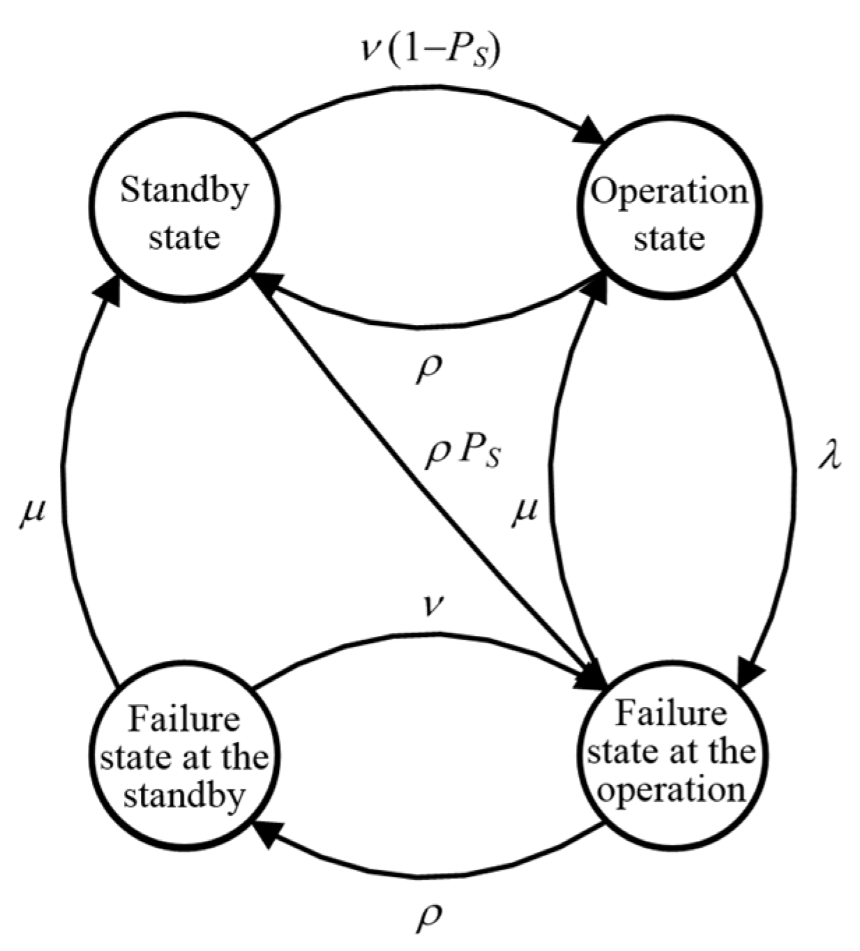
  • Two-state model—in case of continuous service; determined by the failure rate λ and the repair rate μ,
  • Four-state model—in case of peak service; shown in Figure 1
Both the standby anticipation rate ρ and operation rate ν should be determined individually depending on the analyzed electric distribution system. The reliability parameters of engine-driven generators (EDG) and turbine-driven generators (TDG) can be found in Table 2. The values of parameters ν and ρ have been arbitrarily selected.
One can observe a much lower failure rate λ for generation units (both EDG and TDG) operating in peak service. This fact obviously results from less wear of individual components of a generation unit. Therefore, the possibility of failure is decreased. The TDG exhibit the lowest failure rates of units in peak service. Simultaneously, the lower repair rate is observed in comparison to other cases. It is attributable to a relatively small number of long-duration events.
In recent years, a new type of gas turbine, microturbine (MT), has become a fully developed technology. As MT’s have only relatively recently been used as the commercial generation sources, there is not wide access to reliability data obtained from a long-time operation of this DG type. The same problem concerns the fuel cells (FC) as a relatively new technology in an industrial and commercial usage.
As in case of EDG and TDG, MT and FC can be modeled using a two-state or four-state Markov chain with the failure rate λ and repair rate μ as well as a probability of unsuccessful DG unit starting PS. For the reliability calculation purpose λ, μ and PS have been obtained from the manufacturers data available only for peak service. The same values of parameters ν and ρ as for EDG and TDG have been assumed. All of these are presented in Table 3.
The reliability parameters presented in Table 3 have been obtained based on the data given by different manufacturers (catalogues and brochures). It is necessary to treat these values a little distrustfully. These reliability parameters come from laboratory research, which cannot reflect the real conditions in an operating process.

3.2.2. Renewable Energy Sources

Among the most popular renewable energy sources in electric distribution systems, there are small hydro power plants (SHPP), small wind-turbine power plants (WTPP) and photovoltaic power plants (PVPP).
The parameters of different energy carriers (i.e., a river flow, wind speed and solar radiation) can be modeled as the homogenous Markov chain with the states representing different intervals of available energy and the transition rates between λij (transition rate from state i to state j). The general reliability model of a renewable generation system is shown in Figure 2.
In order to represent the reliability of particular types of renewable energy sources, the authors of this paper have found an exemplary number of states, fraction of DG rated apparent power corresponding to the state and values of the transition rates between the states [29,62,65]. All of these are presented in Table 4, Table 5 and Table 6.
It is necessary to mention the values of fraction the DG rated apparent power given in Table 4. The state U.1 concerns a situation when a wind speed is less than the cut-in wind speed of a wind turbine and the power generation equals 0. No power generation is also in the state U.4. In this case, the wind speed is greater than the cut-out wind speed when a wind turbine is switched off.

3.3. Information and Communication Devices

To implement future smart grid functions, the information and communication technology (ICT) is needed. The ICT devices integrated in a power system collect, process and transfer data within the infrastructure. This requires robust communication channels to ensure reliable data flow. For that they use different sorts of communication media, such as Power Line Communication (PLC), Digital Subscriber Lines (xDSLs), fiber optics, IEEE 802.11 (WLAN), IEEE 802.16 (WiMAX), GSM/GPRS, IEEE 802.15.4 (Zigbee), depending on application, technical characteristics and feasibility [41,66]. Several types of devices are installed in integrated communication networks in smart grids, such as phasor measurement unit (PMU), remote terminal unit (RTU), programmable logic controller (PLC), gateway, router, modem, Digital Protective Relay (DPR), Digital Fault Recorder (DFR), PQ meter and smart meter. The types of these devices depend on their application and tasks such as measuring the electrical parameters, controlling the automation systems, transferring collected data and resaving control signals from the control center applications. The comparison of ICT devices, protocols and typical functions in power system is given in Table 7.
Communication network equipment can fail causing interruptions in data transfer, information exchange and other corresponding services. Both hardware and software can be affected for various reasons, impacting the reliability of the communication network. The reliability parameters like mean time between failure (MTBF) and mean time to repair (MTTR) for chosen devices: phasor measurement unit (PMU), remote terminal unit (RTU), programmable logic controller (PLC), gateway and router are given in Table 8. These values are calculated based on literature research on simulation models, laboratory tests and vendors’ data presented in [70,71,72].

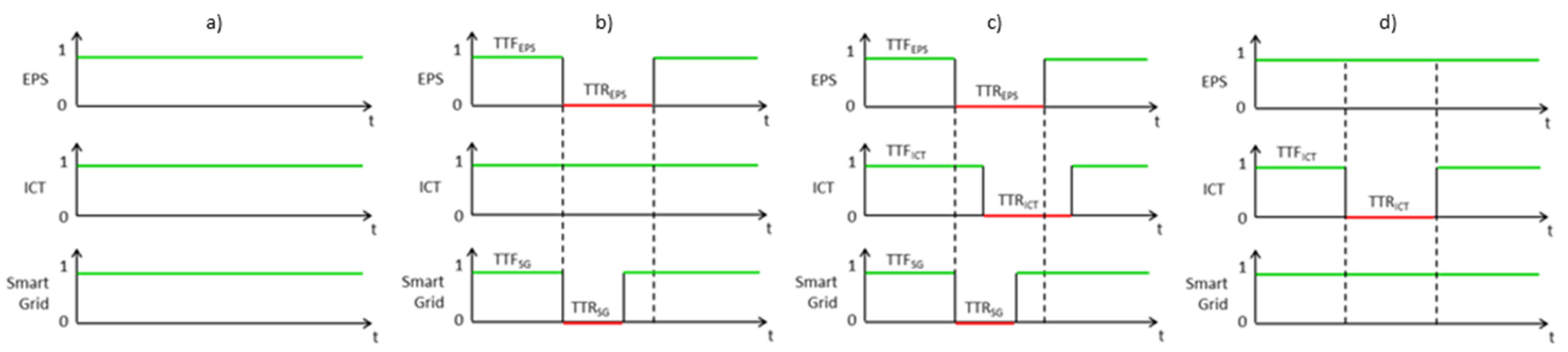
3.4. Interdependencies Modeling of Coupled Electric Power System and ICT Infrastructures

With the rise of smart grid technologies, the interdependencies of communication technologies and electric power systems become an important aspect in the development of both networks [73]. Modeling such interdependencies will be even more complex in the planning and future operation of multi-energy systems (MES) integrating various energy converters and sources of different physical nature [74].
Infrastructures interdependencies are based on physical and functional relationships among individual components both within and between systems. To characterize the effects of failure propagation from the single component or system to mutually dependent interconnected systems the structure modeling of complex infrastructures can be used [75]. The individual operating conditions of the component in the system can be analyzed and the fault propagation can be reduced by having fast recognition of threats, redundancy design and alternative modes of operation [76]. The concept of complex networks theory [77], which is based on the graph theory, can be used to describe and analyze critical infrastructures on a large scale with multifaceted topologies [78]. The interdependency modeling techniques of coupled infrastructures for integrating ICT within the electric power system (EPS) are offered in [33,34].
A graph can represent a network with its set of components and connections between them. Applying graph representation to the coupled EPS and ICT infrastructures, the vertices indicate system components such as buses, gateways and routers while edges correspond to the power lines, cables and communication links. In order to characterize the interdependencies between the infrastructures they can be classified as follows:
  • Connection of an electric node with another electric node, which characterize typical power flow in the electric power grid;
  • Connection of a communication node with another communication node that corresponds to a data flow;
  • Connection of an electric node to a communication node that represents an electricity supply for the ICT infrastructure;
  • Connection of a communication node to an electric node which is responsible for sending and requesting information to and from the power system component.

3.5. Tool for Reliability Analysis

The reliability assessment in electric power distribution systems has been carried out with the use of DIgSILENT PowerFactory software (PF). This software enables an assessment of different reliability indices for power systems in a generation area (hierarchical level HL I) as well as in transmission and distribution system (hierarchical levels HL II and HLIII adequately).
The procedure of a reliability assessment in PF is shown in Figure 3, according to [51].
The first step is modeling an electric power network structure where technical requirements are met (no overloading, acceptable voltage deviations, etc.). For all main network components, the failure models are defined by giving a description of the appropriate probability distributions.
The next stage of the reliability assessment is to generate a list of system states relevant with the failure models and load models. In other words, it is a combination of one or more simultaneous faults and a specific load condition. For each system state, some defined power system reactions are analyzed such as:
  • Automatic stand-by switching on (ASS),
  • Fault clearance by using protection equipment,
  • Automatic power restoration (APR) by opening separating switches (fault separation) and closing normally open switches.
Finally, the system state generation combined with the failure effect analysis updates the calculation of statistic indices. The detailed description of the used algorithm in PF can be found in [79].

4. Reliability Analysis of Electric Power Network

4.1. Assumptions and Limitations

The urban and rural structures of present electric distribution networks (UDN, RDN) with distributed generation have been investigated. Different structures of future distribution networks with embedded generation have been also analyzed, such as: active managed MV distribution network (AMDN) and MV distribution network with connected LV microgrids (DNMG).
The diagrams and parameters of all the basic structures (as a starting point of analysis) are shown in detail in Appendix A, Appendix B, Appendix C and Appendix D.
In Poland any part of the electric distribution system (both MV and LV network) controlled by distribution system operators cannot operate in islanded mode. The autonomous operation is admitted only for power networks and installations belonging to a consumer. For that restriction, the islanded operation of UDN and RDN is not admitted.
In the loop structures, i.e., UDN and DNMG, the ASS as well as the APR have been considered in the reliability assessment. All the MV distribution system models do not take into consideration a possibility of power supply reserve (e.g., with the use of ASS) on the level of LV distribution network
For all investigated DG sources, the reliability models described in Section 3.2 have been assumed. The reliability models of the energy storages (chemical battery and flywheel) have been not considered in this analysis.

4.2. Results of Test Calculations

Before the reliability indices have been calculated, the load flow analysis had been carried out for all investigated distribution network structures. Branch overloading and the excess of permissible voltage deviation in nodes has not been observed.
All the calculated system reliability indices for all considered present and future distribution networks are presented in Table 9, Table 10, Table 11 and Table 12.
Three variants of DG unit location are considered. Based on UDN_1 variant as a basic UDN structure (see Figure A1), a node including the PVPP and BES connected changes from no. 5 to no. 1 (UDN_2) and no. 8 (UDN_3). In each variant, three cases of different power generation levels of the considered PVPP and BES are analyzed, i.e., Case_1—51 kW, Case_2—100 kW and Case_3—510 kW. The other DG sources do not change the location in all variants and the power generation values in all cases.
There are also three variants of DG unit location to be considered. Based on RDN_1 variant as a basic RDN structure (see Figure A3), a node the WTPP and BES are connected to changes from no. 72 to no. 43 (RDN_2) and no. 71 (RDN_3). In each variant, three cases of different power generation levels of the considered WTPP and BES are analyzed, i.e., Case_1—2.4 MW, Case_2—1.6 MW and Case_3—0.8 MW. The other DG sources do not change the location in all variants and the power generation values in all cases.
Three variants of MG location are considered. Based on DNMG_1 variant as a basic DNMG structure (see Figure A4), a MG is connected to changes from no. 6 to no. 3 (DNMG_2) and no. 1 (DNMG_3). In the second variant (DNMG_2) a load equivalent is shifted from node no. 3 to node no. 6. In the third variant (DNMG_3) an additional load equivalent is connected to node no. 6 (P = 100 kW, Q = 20 kvar). In each variant the change of only one of two microsources in considered MG is analyzed in three cases: Case_1—WTPP (170 kW); MT (30 kW), Case_2—WTPP (170 kW); FC (30 kW), Case_3—WTPP (170 kW); PVPP (30 kW). In all the cases reactive power generated in microsources is equal to 0 kvar.
Three variants of DG unit location are considered. Based on AMDN_1 variant as a basic AMDN structure (see Figure A5), a node the DG unit is connected to changes from no. 4 to no. 2 (AMDN_2) and no. 1 (AMDN_3). In each variant, five cases of different types of the considered DG unit are analyzed, i.e., Case_1—WTPP, Case_2—PVPP, Case_3—EDG, Case_4—TDG, Case_5—SHPP. The change of power generation level of the DG unit is not considered.
For AMDN_1 variant an impact of automatic on-load tap changer at the 110 kV/MV transformer on the maximum active and reactive power generated by a DG unit has been analyzed as well. The branch power capacity and permissible voltage deviation (±10%) was the criterion used to determine the maximum power generation. The first investigated case assumes the peak load and 110 kV/MV transformer operation without on-load tap changer. Maximum values of active and reactive power generated by the DG source are P = 14.3 MW and Q = 4.3 Mvar adequately at +10% voltage deviation. In the second case (peak-off load and transformer operation without on-load tap changer) the DG unit can generate only P = 1.8 MW and Q = 0.54 Mvar. The last case assumes the automatic on-load tap changer at the transformer as well as the peak-off load, the DG source can generate the power up to the cable load capacity (the line between nodes no. 3 and 4).

4.3. Observations

Based on the test calculation results the following observations have been made:
  • Looking at the reliability indices calculated for UDN and RDN one can certainly state that location and type of DG source does not directly affect the power supply reliability. The APR application in UDN definitely improves all the investigated reliability indices, i.e., SAIFI, CAIFI, SAIDI, CAIDI, EENS, ASAI, ASUI).
  • Three considered variants of DG source location in AMDN have been compared. Looking at ASAI index, the highest value is for “AMDN_1” and the lowest one is for “AMDN_2”. There is also an impact of DG types on both the interruption frequency and interruption duration.
  • An impact of DG type on reliability indices is also noticeable for DNMG. For all considered DNMG variants, the lowest ASAI value is observed in “Case_3” with WTPP and PVPP connected to a microgrid. Analyzing three variants of microgrid locations, the highest ASAI value is observed for “DNMG_1”. In addition, “DNMG_3” characterizes the lowest value of ASAI index.
  • Both the interruption frequency (SAIFI, CAIFI) and interruption duration (SAIDI, CAIDI) for UDN are lower than for RDN.
  • The interruption frequency (SAIFI, CAIFI) calculated for RDN is about tenfold higher than for AMDN with DG unit connected (except the variant AMDN_3 in which the ratio is about four). An interesting observation about interruption durations is made. The values of CAIDI index are almost comparable to one another, but the SAIDI for AMDN is over twelvefold lower than for RDN structure. This observation shows the strongly irregular distribution of the repair duration in the analyzed AMDN structure.
  • DNMG with connected LV microgrids does not significantly improve the power supply reliability in comparison to UDN with APR.

5. Smart Grid Reliability Assessment

5.1. Model Structure

A simple distribution system structure was created to analyze the reliability assessment of an electric power network coupled with a communications network [80,81], see Figure A6 in Appendix E. Integrated communication allows for monitoring all nodes in the network, and thus faster detection of the location of failures in the power network and taking corrective actions. The component aging is disregarded and only the constant failure rate related to their useful life is analyzed. Since failures in the power system usually occur randomly, the sequential Monte Carlo method was employed to simulate and assess a smart grid’s reliability over time. The method produces a distribution of possible outcomes rather than a single expected value.
The artificial operating/failure histories of the relevant smart grid elements are generated. The period during which the element is operating is called time to failure (TTF). The period during which the element fails is called time to repair (TTR).
The parameters TTF, TTR constitute random variables and may have different probability distributions. Exponential distribution is used here to assess the reliability of both the electric power distribution system and the communications network. The exponential distribution’s probability distribution function is described as follows [80,82]:
f ( t ) = { λ e λ t , 0 < t < 0 , o t h e r w i s e
The method for generating an artificial failure history of a component is presented in Figure 4. Each time interval is computed with different random numbers. This simulates contingencies occurring in a real system realistically.
TTF and TTR are calculated for a given failure rate and repair rate from Table 13 with the formulas [83]:
T T F i = 1 λ ln ( u i )
T T R j = 1 μ ln ( u j )
where ui, uj are random numbers uniformly distributed in the range of 0–1 and λ and μ are the failure rate and the repair rate, respectively.
The communications infrastructure in smart grid supplies additional information on power system states, thus improving overall network performance. It enables faster detection of and response to failures or even prevents their occurrence. Accessing information faster facilitates earlier dispatching of service teams or faster responses by different system operators to potential imbalances in power systems, for instance.
By extension, communications shorten interruption times. This method, thus, entails shortening interruption times by shortening the time to repair for combined system. The shorter time to repair is denoted as TTRSG (see Figure 5) and simulated. Since communications are assumed to improve distribution system reliability, their absence or failure do not diminish an electric power system’s (EPS) performance, as shown on the right in Figure 5.

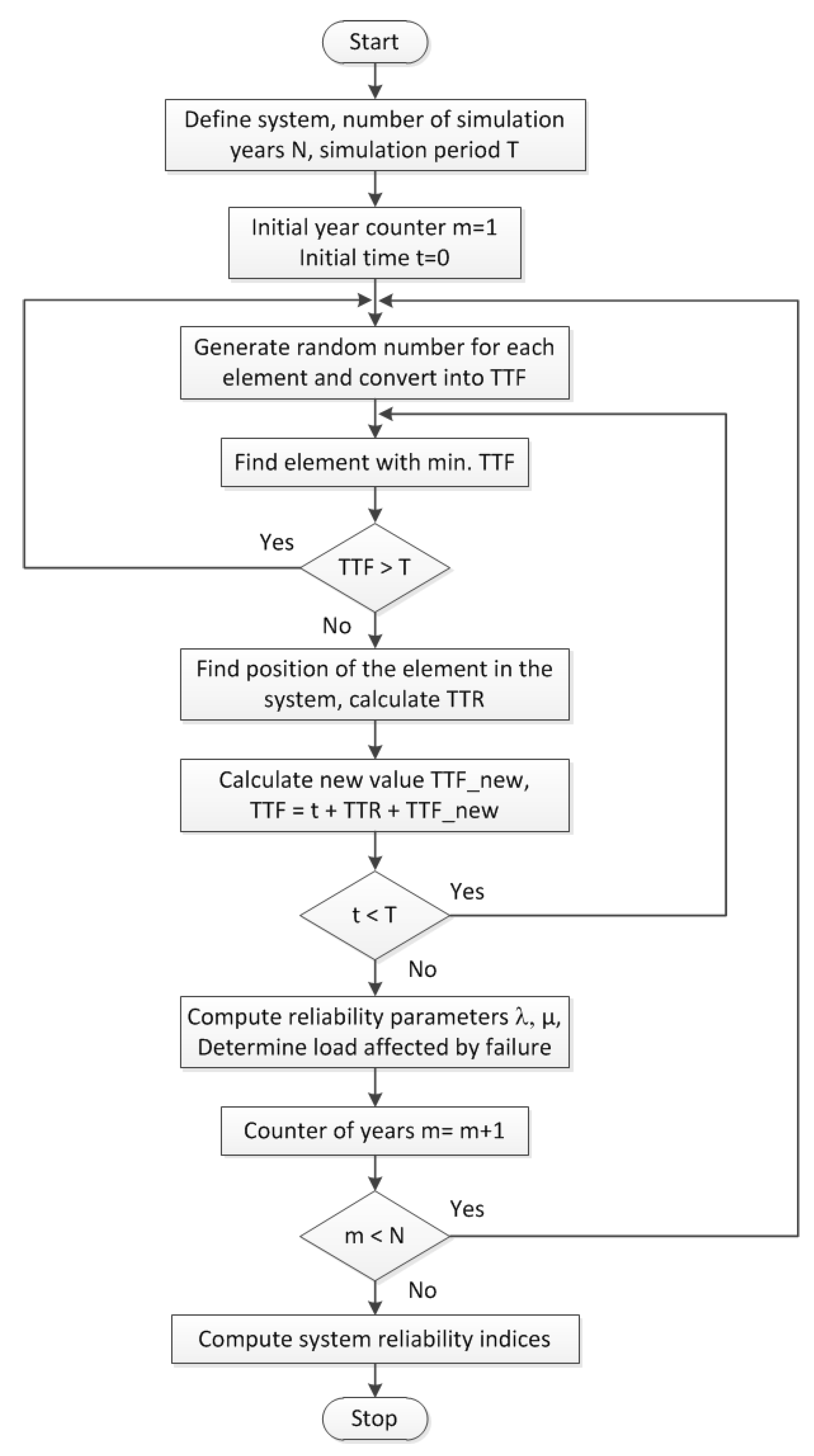
5.2. The Algorithm Used

The reliability simulations are based on the time sequential Monte Carlo technique. This method has been adapted into the proposed approach of Smart Grid reliability assessment. The algorithm used to compute reliability indices of electric power distribution systems (EPS), communications networks (ICT) and integrated Smart Grid (SG) system is presented in a block diagram in Figure 6.
The program starts with definition of system input data such as network topology with location of the components, failure and repair rates and connected loads. The number of sample years (N) and simulation period (T) are also entered in this step. The simulation begins with generating random numbers [0,1] for each element in the system and converting them into time to failure (TTF) using equation 4. In the next step, the element with the shortest TTF is determined, i.e., the component that will fail first. In the conditional block, it is then checked to see if the found minimal TTF value matches within one year. If this is not a case, it means that the TTF is longer than 8760 h and within this year no failure occurs. Further steps will be skipped and random numbers of TTF are computed again for all elements. If the TTF is shorter than 8760 h, the time to repair (TTR) will be computed for that element which indicates its out of operation state duration. Moreover, its location in the interconnection matrix as well as the location of any load nodes which can be influenced by the given component is also determined. After that, a new random number is generated for that component and converted into new TTF. Simulation time has to be updated for each element according to Equation (11).
TTF = t + TTR + TTF _ new
The updated TTF value indicates subsequent time of failure occurrence and is compared with previously generated TTFs of other components. After that, the TTR for other elements can be computed. These procedures are repeated in a loop for each element until the simulation period (e.g., one year) is completed and all of the simulation sequences comprising the defined number of years are finished. Then, the reliability parameters of each component, such as failure and repair rate as well as unavailability, are computed. Finally, based on these parameters, the reliability indices for the whole system are calculated for the total sample number of years (N).

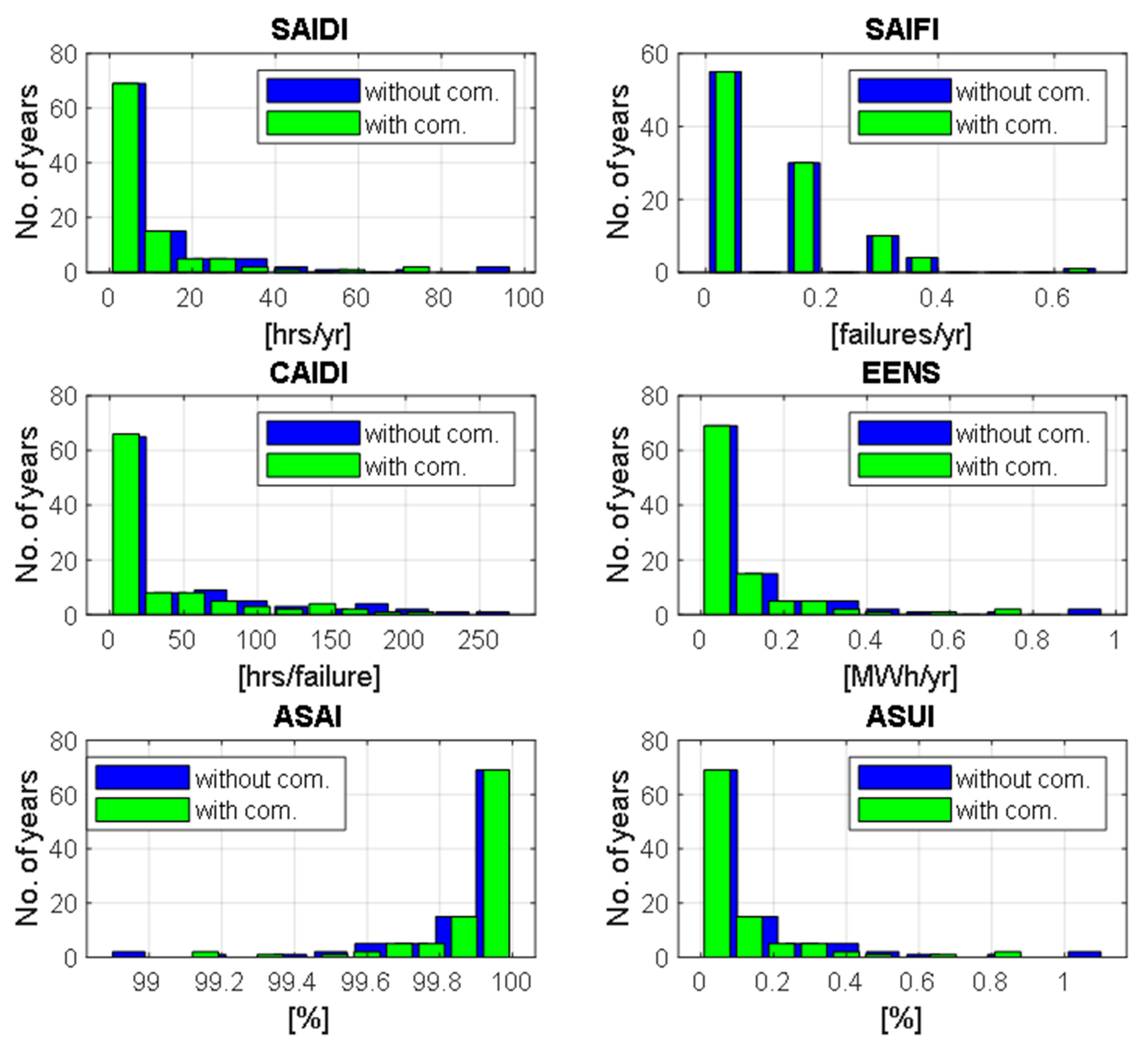
5.3. Simulation Results

The simulations of an integrated smart grid system were run with the structure illustrated in Figure A6. In the simulations, component failures and the existence of communication were considered, and generation parameters were omitted. In order to calculate the relevant reliability indicators, the number of customers has been taken into account.
Simulations of N = 100 years with the step-in sequence of one year (8760 h) with the resolution of one hour were run using the input data presented in Table 13. Faster responses to failures, shorten the time to repair for the smart grid. The results of reliability parameters obtained with time sequential simulation are strongly influenced from the failure, repair rates and system structure. The distribution of reliability indices significantly depends on the number of simulated years.
Simulation results are presented in Table 14 and Figure 7. The average system indices show that the electric power system with a communications infrastructure is more reliable. The presence of ICT shortens interruption times, represented by the SAIDI index.
Moreover, the range of index distributions shifts toward zero in systems with communications, reflecting improved reliability. Distributions of the SAIFI index representing the number of interruptions in one year are identical for systems with and without communications because only the durations of interruptions change in both scenarios but the number of interruptions in one year remain constant.
The CAIDI index representing the average interruption duration is significantly smaller in electric power systems with ICT than in systems without communications. This is due to the shorter break times.

6. Conclusions

Electrical component failures in distribution systems have been proven the cause of the majority of power interruptions in electric power system.
The number, location, and type of DG sources in existing (conventional) company-owned distribution networks that may not operate in islanded mode have no direct impact on reliability indices. However, a DG unit connection to a distribution network may cause a load alleviation in lines, transformers, etc. and this phenomenon varies the form of the risk function of power system components. The DG sources connected to a distribution network indirectly improves electric service reliability for consumers. DG units may increase voltage in busbars and terminals and short-circuit currents in a distribution system.
Power supply is chiefly improved by providing power redundancy and using remote control switches with distribution system automation, such as ASS, APR and AR (automatic reclosing). The reliability calculations corroborate this. Power interruption frequency and power interruption duration are lower in urban looped distribution networks than in rural distribution networks with feeders supplied from one point. The continued growth of DG capacity in distribution systems requires research and development of new (future) distribution network structures, e.g., actively managed networks (smart grids), microgrids, clustered networks, etc. All of these networks are assumed to be capable of operating autonomously (i.e., islanded and unconnected to the main grid) and to be equipped with distribution system automation (e.g., ASS, APR and AR).
The calculations confirm that the future distribution network structures have higher electrical service reliability than existing distribution networks. Future distribution systems have lower interruption frequencies and durations.
Actively managed distribution networks appear to be a promising idea [84]. Assuming the voltage limitation on network busbars and terminals, the impact of the active on-load tap changer in the 110 kV/MV transformer on the maximum active and reactive power generated by a DG source has been analyzed. This study has demonstrated that the automatic voltage regulator (AVR) at the transformer allows the increase of installed capacity of DG unit connected to the distribution network.
Considering the impact of DG type and locations in future electric distribution networks on the power supply reliability, the results of reliability assessment allow the formulation of the following remarks:
  • Power supply continuity is higher when DG sources are based on conventional fuels (gas, diesel oil, etc.). The installation of renewable DG units (energy carriers that are hard to forecast) delivers worse results.
  • Types of microsources in distribution networks with connected LV microgrids affect the reliability indices. This is noticeable in installed microsources based on energy carriers dependent on weather conditions.
  • The location of DG sources in distribution systems also affects electrical service reliability. The most favorable reliability indices are obtained when the potential maximum number of energy consumers are double-feed (loop: transformer substation—DG unit). In case of aggregation of supplying sources at the one network busbar or terminal, worse reliability indices are observed.
  • The appropriate level of DG power generation is a significant issue. The DG power available ensures peak loads are covered. The level of power generation is often limited by branch power capacity and maximum allowable voltage deviation. Active voltage regulation in power transformers can resolve voltage level problems.
The authors intend to focus on optimizing future distribution system structures and devising an optimal development strategy for existing distribution networks in future studies. This will require the determining of accurate reliability models of electric power equipment, protection and automation systems, DG sources and energy storage systems in different types of network structures.
The use of information and communications technology to monitor, control and protect power systems is an important way to meet the challenges of continuously developing electric power grids. The installation of measurement sensors, automated control systems and communication devices will increase the complexity of such integrated systems, thus requiring new methods for designing and optimal integrating of advanced communications systems in electric power grids.
A reliability assessment of smart grids consisting of an electric power distribution system and an integrated communications network based on Monte Carlo simulation was developed and tested in this study. The simulation algorithm delivers the distributions and average values of reliability indices for smart grids, electric power systems and communications networks. This enabled analyzing the influence of the coexistent ICT infrastructure on the power distribution system’s reliability and, thus, the entire smart grid. Although some assumptions were made in the methodology to model the systems, the algorithm developed delivers valuable results for the assessment of reliability when designing and optimizing systems. Widespread use of a reliable information and communications infrastructure will improve smart grids’ functionality and reliability.
Since this study concentrates on the monitoring of smart grids with advanced ICT, future studies ought to analyze their control and protection. Applying reliable control and protection schemes to the system will help minimize outages and their impact on overall system operation. Future studies ought to examine more complex models of ICT network operation, including several levels of communication performance, e.g., full communication of all components, full communication of all components with limited quality of service (QoS) and limited communication.

Author Contributions

Conceptualization, M.P., J.W. and B.A.; methodology, J.W. and B.A.; investigation, J.W. and B.A.; supervision, M.P. and. P.K.; writing, M.P., J.W., T.W. and B.A.; visualization, J.W. and T.W. All authors have read and agreed to the published version of the manuscript.

Funding

This study was funded in part by the Polish Ministry of Education and Science in the research project “National Electrical Power Security” (PBZ-MEiN-1/2/2006; tasks no. 5.3.5 and 5.3.6).

Informed Consent Statement

Not applicable.

Data Availability Statement

Not applicable.

Acknowledgments

Three of four test MV distribution power network structures used in this paper has been developed under the research project “National Electrical Power Security” supported by the Polish Ministry of Education and Science. Similarly, reliability calculations in the test networks have been carried out under the research project. The smart grid reliability research was carried out within the SECVER project supported by the Federal Ministry of Economic Affairs and Energy (BMWi) in Germany.

Conflicts of Interest

The authors declare no conflict of interest.

Abbreviation

The following abbreviations are used in this manuscript:
AMDNActive managed distribution network
APRAutomatic power restoration
ARAutomatic reclosing
ASAIAverage service availability index
ASUIAverage service unavailability index
ASSAutomatic stand-by switching on
AVRAutomatic voltage regulator
BESBattery energy storage
BTPPBiogas-turbine power plant
CAIDICustomer average interruption duration index
CAIFICustomer average interruption frequency index
DGDistributed generation
DGUDistributed generation unit
DNMGUrban distribution network with connected microgrids
EDGEngine-driven generator
EENSExpected energy not supplied
EPSElectric power system
ETElectric traction substation
EXPExponential
FCFuel cell
FMECAFailure mode effects and criticality analysis
GAMGamma
GTGrounding transformer
GTPPGas-turbine power plant
GUMGumbel
HLHierarchical level
ICTInformation and communication technology
IECInternational Electrotechnical Commission
IPIndustrial park
ITInformation technology
LNORLog-normal
LTELong term evolution
LVLow voltage
MGMicrogrid
MG(G)Microgrid generation
MG(L)Microgrid load
MTMicroturbine
MTBFMean time between failure
MTTRMean time to repair
MVMedium voltage
MVUSMV urban distribution substation
NORNormal
PARPareto
PFPowerFactory software
PFCBPFC capacitor bank
PLCProgrammable logic controller
PMUPhasor measurement unit
PSPower system
PVPhotovoltaic
PVPPPhotovoltaic power plant
QoSQuality of service
RDNRural distribution network
RESRenewable energy source
RTURemote terminal unit
R&PUResidential and public utility
SCADASupervisory control and data acquisition
SAIDISystem average interruption duration index
SAIFISystem average interruption frequency index
SGSmart grid
SHPPSmall hydro power plant
TDGTurbine-driven generator
TTFTime to failure
TTRTime to repair
UDNUrban distribution network
WEIWeibull
WTPPWind-turbine power plant

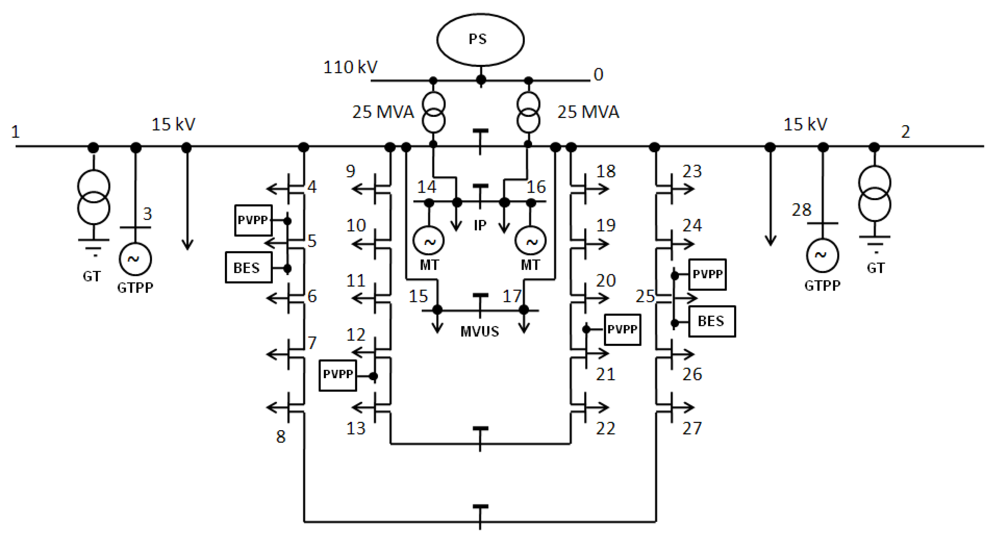
Appendix A. UDN Structure

Figure A1. MV urban distribution network with the distributed generation sources (PS—power system, PVPP—photovoltaic power plant, BES—battery energy storage, MT—micro-turbine, GTPP—gas-turbine power plant, GT—grounding transformer, MVUS—MV urban distribution substation, IP—industrial park).
Energies 15 05311 g0a1
Table A1. Distributed generation sources and energy consumers connected to the urban MV distribution network.
Node No.PLOAD/PGEN
[kW]
QLOAD
[kvar]
Load/
DG Type
Node No.PLOAD/PGEN
[kW]
QLOAD
[kvar]
Load/
DG Type
150001500R&PU1547001700R&PU
250001500R&PU16200-MT
31200-GTPP161080420IP
4510185R&PU1746501835R&PU
5530210R&PU18545215R&PU
530-BES19310120R&PU
551-PVPP20315115R&PU
6305120R&PU21335110R&PU
7300110R&PU2151-PVPP
8530210R&PU22540195ET
9320115R&PU23495180R&PU
10540210R&PU24535195R&PU
11495180R&PU25325105R&PU
12340110R&PU2551-PVPP
1251-PVPP2530-BES
13300120R&PU26325105R&PU
141060415IP27540195R&PU
14200-MT281200-GTPP
Types of energy consumers: R&PU—residential and public utility, IP—industrial (park), ET—electric traction substation. The nodes the DG sources are connected to are marked as gray background.
Figure A2. Typical daily load profile (15-min intervals) for residential consumers (a line with the triangles) as well as industrial parks and electric traction substation (a line with the quadrants); based on [85].
Energies 15 05311 g0a2
Table A2. Line parameters of the urban MV distribution network.
From
Node No.
To Node No.Line TypeLength
[m]
From
Node No.
To Node No.Line TypeLength
[m]
133xXUHAKXS1 × 1202000115HAKnFty 3 × 2403000
143xYHAKXS1 × 120110216HAKnFty 3 × 1201600
453xYHAKXS1 × 120250217HAKnFty 3 × 2403000
563xYHAKXS1 × 1201002283xYHAKXS 1 × 120190
673xYHAKXS1 × 12013018193xYHAKXS 1 × 120100
783xYHAKXS1 × 12016019203xYHAKXS 1 × 120110
8273xYHAKXS1 × 12017020213xYHAKXS 1 × 120130
193xYHAKXS1 × 12020021223xYHAKXS 1 × 12080
9103xYHAKXS1 × 1201202233xYHAKXS 1 × 120120
10113xYHAKXS1 × 12014023243xYHAKXS 1 × 120200
11123xYHAKXS1 × 12017024253xYHAKXS 1 × 12080
12133xYHAKXS1 × 1208025263xYHAKXS 1 × 120140
13223xYHAKXS1 × 12014026273xYHAKXS 1 × 12090
114HAKnFty 3 × 12016002283xXUHAKXS1 × 1202500
XUHAKXS—single-Al core cable, radial field, polythene-coated, polythene sheath, YHAKXS—single-Al core cable, radial field, polythene-coated, polyvinyl chloride sheath, HAKnFty—triple-Al core cable, radial field, paper-coated, steel armor, polyvinyl chloride sheath.

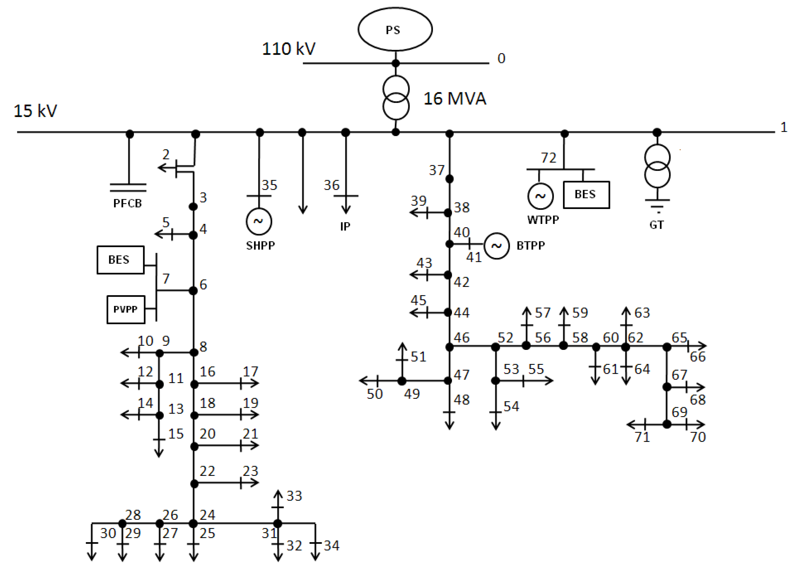
Appendix B. RDN Structure

Figure A3. Rural MV distribution network with the distributed generation sources (PS—power system, PVPP—photovoltaic power plant, BES—battery energy storage, SHPP—small hydropower plant, BTPP—biogas-turbine power plant, WTPP—wind-turbine power plant, PFCB—PFC capacitor bank, GT—grounding transformer, IP—industrial park).
Energies 15 05311 g0a3
Table A3. Distributed generation sources and energy consumers connected to the rural MV distribution network.
Node No.PLOAD/PGEN
[kW]
QLOAD
[kvar]
Load/
DG Type
Node No.PLOAD/PGEN
[kW]
QLOAD
[kvar]
Load/
DG type
140001400R&PU361595580IP
2565185R&PU39335120R&PU
521075R&PU411200-BTPP
78530R&PU4313550R&PU
7200-PVPP4514045R&PU
7200-BES487530R&PU
1014545R&PU5013550R&PU
1213550R&PU5120075R&PU
1412540R&PU5419075R&PU
1519070R&PU5521075IP
1720580R&PU5713550R&PU
1912550R&PU597530R&PU
2112545IP6121075R&PU
237530R&PU6321575R&PU
2520075R&PU6414045R&PU
2722575R&PU6620070R&PU
2912045R&PU6812550R&PU
3012550R&PU7014045R&PU
3212050R&PU718530R&PU
3313045R&PU722400-WTPP
349030R&PU72500-BES
352000-SHPP----
The nodes the DG sources are connected to are marked as gray background.
Table A4. Line parameters of the rural MV distribution network.
From
Node No.
To Node No.Line TypeLength
[m]
From
Node No.
To Node No.Line TypeLength
[m]
123xYHAKXS 1 × 1205001373xYHAKXS1 × 120450
233xYHAKXS 1 × 120150373870 AFL200
3470 AFL160383950 AFL100
4550 AFL130384070 AFL150
4670 AFL200404170 AFL90
6750 AFL50404270 AFL180
6870 AFL120424350 AFL70
8950 AFL310424470 AFL180
91050 AFL60444550 AFL120
91150 AFL210444670 AFL210
111250 AFL80464750 AFL200
111350 AFL160474850 AFL90
131450 AFL50474950 AFL150
131550 AFL120495050 AFL90
81670 AFL160495150 AFL110
161750 AFL100465270 AFL140
161870 AFL180525350 AFL200
181950 AFL90535450 AFL60
182070 AFL210535550 AFL190
202150 AFL160525670 AFL210
202270 AFL130565750 AFL120
222350 AFL110565870 AFL130
222470 AFL120585950 AFL70
242550 AFL140586070 AFL200
242650 AFL180606150 AFL130
262750 AFL160606270 AFL160
262850 AFL150626350 AFL200
282950 AFL70626450 AFL130
283050 AFL290626550 AFL140
243150 AFL200656650 AFL210
313250 AFL120656750 AFL140
313350 AFL60676850 AFL80
313450 AFL300676950 AFL120
1353xYHAKXS 1 × 1204000697050 AFL90
1363xYHAKXS 1 × 1202500697150 AFL200
243150 AFL2001723xYHAKXS1 × 1203000
AFL—steel-cored aluminum conductor.

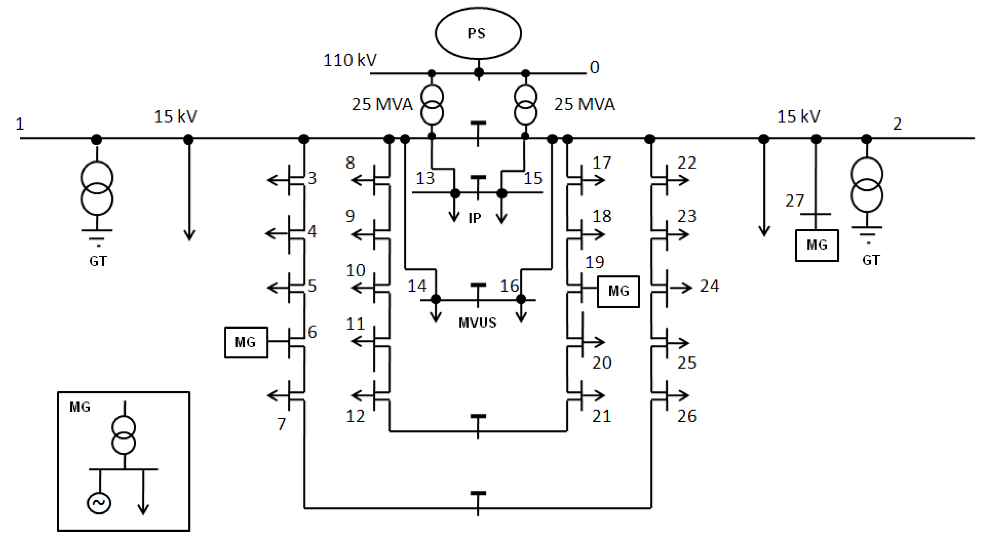
Appendix C. DNMG Structure

Figure A4. MV distribution network with connected LV microgrids (PS—power system, MG—microgrid, IP—industrial park, MVUS—MV urban distribution substation, GT—grounding transformer).
Energies 15 05311 g0a4
Table A5. Distributed generation sources and energy consumers connected to the MV distribution network with LV microgrids.
Node No.PLOAD/PGEN
[kW]
QLOAD
[kvar]
Load/
DG Type
Node No.PLOAD/PGEN
[kW]
QLOAD
[kvar]
Load/
DG Type
150001500R&PU1646501835R&PU
3510185R&PU17545215R&PU
4530210R&PU18310120R&PU
5305120R&PU19580145MG(L)
6580145MG(L)19200-MG(G)
6200-MG(G)20335110R&PU
7530210R&PU21540195R&PU
8320115R&PU22495180R&PU
9540210R&PU23535195R&PU
10495180R&PU24325105R&PU
11340110R&PU25325105R&PU
12300120R&PU26540195R&PU
131060415IP250001500R&PU
1447001700R&PU27580145MG(L)
151080420IP27200-MG(G)
Energy consumers and power generation types: MG(L)—microgrid load, MG(G)—microgrid generation. The nodes the MG generations are connected to are marked as gray background.
Table A6. Line parameters of the MV distribution network with LV microgrids.
From
Node No.
To Node No.Length
[m]
From
Node No.
To Node No.Length
[m]
131102151600
342502163000
45100217190
561301718100
671601819110
7261701920130
18200202180
89120222120
9101402223200
1011170232480
1112802425140
1221140252690
11316002272500
1143000
The MV distribution network with connected LV microgrids consists entirely of underground cables 3x(YHAKXS 1 × 240).

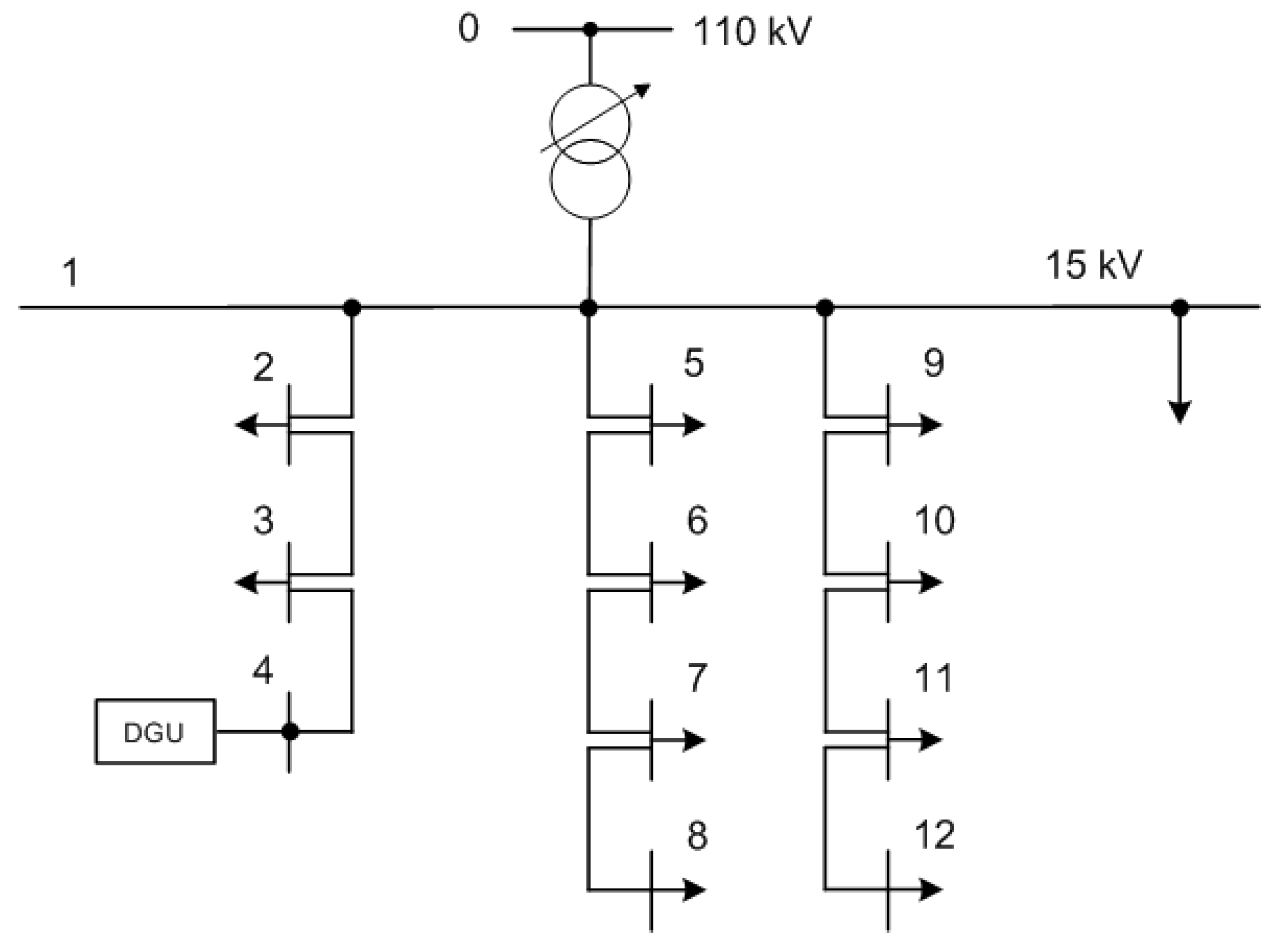
Appendix D. AMDN Structure

Figure A5. Actively managed MV distribution network with the DG unit (based on [84]).
Energies 15 05311 g0a5
Table A7. Energy consumers connected to the actively managed MV distribution network.
Node No.PLOAD/PGEN
[kW]
QLOAD
[kvar]
Load/
DG Type
Node No.PLOAD/PGEN
[kW]
QLOAD
[kvar]
Load/
DG Type
170002100R&PU8400130R&PU
2400130R&PU9450150R&PU
3500165R&PU10550165R&PU
5450135R&PU111600640IP
62000800IP12400120R&PU
7550165R&PU
Table A8. Line parameters of the actively managed MV distribution network.
From
Node No.
To Node No.Length
[m]
From
Node No.
To Node No.Length
[m]
1250078140
2315019300
34250910140
154001011180
561501112120
The actively managed MV distribution network consists entirely of underground cables 3x(YHAKXS 1 × 240).

Appendix E. Smart Grid Structure

Figure A6. A proposed benchmark system for coupled electric power system and communications network (N—number of customers) (based on [80,81]).
Energies 15 05311 g0a6

References

  1. Chowdhury, A.; Koval, D. Power Distribution System Reliability. In Practical Methods and Applications; John Wiley & Sons, Inc. Publication: Hoboken, NJ, USA, 2009. [Google Scholar]
  2. Fotuhi-Firuzabad, M.; Rajabi-Ghahnavie, A. An Analytical Method to Consider DG Impacts on Distribution System Reliability. In Proceedings of the 2005 IEEE/PES Transmission & Distribution Conference & Exhibition: Asia and Pacific, Dalian, China, 18 August 2005. [Google Scholar]
  3. Bae, I.-S.; Kim, J.-O. Reliability Evaluation of Distributed Generation Based on Operation Mode. IEEE Trans. Power Syst. 2007, 22, 785–790. [Google Scholar] [CrossRef]
  4. Hlatshwayo, M.; Chowdhury, S.; Chowdhury, S.P.; Awodele, K.O. Reliability Enhancement of Radial Distribution Systems with DG Penetration. In Proceedings of the 45th International Universities Power Engineering Conference UPEC2010, Cardiff, UK, 31 August–3 September 2010. [Google Scholar]
  5. Atwa, Y.M.; El-Saadany, E.F. Reliability Evaluation for Distributed System with Renewable Distributed Generation During Islanded Mode of Operation. IEEE Trans. Power Syst. 2009, 24, 572–581. [Google Scholar] [CrossRef]
  6. Martinez-Velasco, J.A.; Guerra, G. Reliability Analysis of Distribution Systems with Photovoltaic Generation Using a Power Flow Simulator and a Parallel Monte Carlo Approach. Energies 2016, 9, 537. [Google Scholar] [CrossRef] [Green Version]
  7. Escalera, A.; Castronuovo, E.D.; Prodanović, M.; Roldán-Pérez, J. Reliability Assessment of Distribution Networks with Optimal Coordination of Distributed Generation, Energy Storage and Demand Management. Energies 2019, 12, 3202. [Google Scholar] [CrossRef] [Green Version]
  8. Kumar, S.; Sarita, K.; Vardhan, A.S.S.; Elavarasan, R.M.; Saket, R.K.; Das, N. Reliability Assessment of Wind-Solar PV Integrated Distribution System Using Electrical Loss Minimization Technique. Energies 2020, 13, 5631. [Google Scholar] [CrossRef]
  9. Ndawula, M.B.; Djokic, S.Z.; Hernando-Gil, I. Reliability Enhancement in Power Networks under Uncertainty from Distributed Energy Resources. Energies 2019, 12, 531. [Google Scholar] [CrossRef] [Green Version]
  10. Kebede, F.; Olivier, J.-C.; Bourguet, S.; Machmoum, M. Reliability Evaluation of Renewable Power Systems through Distribution Network Power Outage Modelling. Energies 2021, 14, 3225. [Google Scholar] [CrossRef]
  11. Verbo, P.; Järventausta, P.; Kiviko, K.; Pylvänäinen, J.; Partanen, J.; Lassila, J.; Honkapuro, S.; Kaipia, T. Applying Reliability Analysis in Evaluation of Life-Cycle Costs of Alternative Network Solutions. In Proceedings of the FPS 2005 International Conference on Future Power Systems, Amsterdam, The Netherlands, 16–18 November 2005; pp. 1–4. [Google Scholar]
  12. Conti, S.; Rizzo, S.A.; El-Saadany, E.F.; Essam, M.; Atwa, Y.M. Reliability Assessment of Distribution Systems Considering Telecontrolled Switches and Microgrids. IEEE Trans. Power Syst. 2014, 29, 598–607. [Google Scholar] [CrossRef]
  13. Paterakis, N.G.; Mazza, A.; Santos, S.F.; Erdinç, O.; Chicco, G.; Bakirtzis, A.G.; Catalão, J.P. Multi-Objective Reconfiguration of Radial Distribution Systems Using Reliability Indices. IEEE Trans. Power Syst. 2016, 31, 1048–1062. [Google Scholar] [CrossRef]
  14. Xu, N.Z.; Chung, C.Y. Reliability Evaluation of Distribution Systems Including Vehicle-to-Home and Vehicle-to-Grid. IEEE Trans. Power Syst. 2016, 31, 759–768. [Google Scholar] [CrossRef]
  15. Lombardi, P.; Hänsch, K.; Arendarski, B.; Komarnicki, P. Information and power terminals: A reliable microgrid infrastructure for use in disaster scenarios. Int. J. Crit. Infrastruct. Prot. 2017, 19, 49–58. [Google Scholar] [CrossRef]
  16. Alotaibi, I.; Abido, M.A.; Khalid, M.; Savkin, A.V. A Comprehensive Review of Recent Advances in Smart Grids: A Sustainable Future with Renewable Energy Resources. Energies 2020, 13, 6269. [Google Scholar] [CrossRef]
  17. Das, S.; Kankanala, P.; Pahwa, A. Outage Estimation in Electric Power Distribution Systems Using a Neural Network Ensemble. Energies 2021, 14, 4797. [Google Scholar] [CrossRef]
  18. Bae, I.-S.; Kim, J.-O. Reliability Evaluation of Customers in a Microgrid. IEEE Trans. Power Syst. 2008, 23, 1416–1422. [Google Scholar]
  19. Parol, M.; Rokicki, Ł.; Parol, R. Towards optimal operation control in rural low voltage microgrids. Bull. Pol. Ac Tech. 2019, 67, 799–812. [Google Scholar]
  20. Xu, X.; Mitra, J.; Wang, T.; Mu, L. Evaluation of Operational reliability of a Microgrid Using a Short-term Outage Model. IEEE Trans. Power Syst. 2014, 29, 2238–2247. [Google Scholar] [CrossRef]
  21. Worku, M.Y.; Hassan, M.A.; Abido, M.A. Real Time Energy Management and Control of Renewable Energy based Microgrid in Grid Connected and Island Modes. Energies 2019, 12, 276. [Google Scholar] [CrossRef] [Green Version]
  22. Costa, P.M.; Matos, M.A. Assessing the contribution of microgrids to the reliability of distribution networks. Electr. Power Syst. Res. 2009, 79, 382–389. [Google Scholar] [CrossRef]
  23. Conti, S.; Nicolosi, R.; Rizzo, S.A. An Analytical Formulation to Assess Distribution System Reliability in Presence of Conventional and Renewable Distributed Generators. In Proceedings of the CIGRE Symposium “The Electric Power System of the Future–Integrating Supergrids and Microgrids”, Bologna, Italy, 13–15 September 2011. [Google Scholar]
  24. Marcos, F.P.; Domingo, C.M.; San Román, T.G.; Arín, R.C. Location and Sizing of Micro-Grids to Improve Continuity of Supply in Radial Distribution Networks. Energies 2020, 13, 3495. [Google Scholar] [CrossRef]
  25. Bie, Z.; Zhang, P.; Li, G.; Hua, B.; Meehan, M.; Wang, X. Reliability Evaluation of Active Distribution Systems Including Microgrids. IEEE Trans. Power Syst. 2012, 27, 2342–2350. [Google Scholar] [CrossRef]
  26. López-Prado, J.L.; Vélez, J.I.; Garcia-Llinás, G.A. Reliability Evaluation in Distribution Networks with Microgrids: Review and Classification of the Literature. Energies 2020, 13, 6189. [Google Scholar] [CrossRef]
  27. Leite Andréa, P.; Borges Carmen, L.T.; Falcäo Djalma, M. Probabilistic Wind Farm Generation Model for Reliability Studies Applied to Brazilian Sites. IEEE Trans. Power Syst. 2006, 21, 1493–1501. [Google Scholar] [CrossRef]
  28. Artigao, E.; Martín-Martínez, S.; Honrubia-Escribano, A.; Gómez-Lázaro, E. Wind turbine reliability: A comprehensive review towards effective condition monitoring development. App. Energy 2018, 228, 1569–1583. [Google Scholar] [CrossRef]
  29. Borges Carmen, L.T.; Pinto Roberto, J. Small Hydro Power Plants Energy Availability Modeling for Generation Reliability Evaluation. IEEE Trans. Power Syst. 2008, 23, 1125–1135. [Google Scholar] [CrossRef]
  30. Ardito, L.; Procaccianti, G.; Menga, G.; Morisio, M. Smart Grid Technologies in Europe: An Overview. Energies 2013, 6, 251–281. [Google Scholar] [CrossRef] [Green Version]
  31. Celli, G.; Ghiani, E.; Pilo, F.; Soma, G. Impact of ICT on the Reliability of Active Distribution Networks. In Proceedings of the CIRED Workshop, Lisbon, Portugal, 29–30 May 2012. [Google Scholar]
  32. Girón, C.; Rodríguez, F.J.; Giménez de Urtasum, L.; Borroy, S. Assessing the contribution of automation to the electric distribution network reliability. Int. J. Electr. Power Energy Syst. 2018, 97, 120–126. [Google Scholar] [CrossRef]
  33. Sanchez, J.; Caire, R.; HadjSaid, N. ICT and Electric Power Systems Interdependencies Modeling. In Proceedings of the Internationaler ETG-Kongress in Berlin, Berlin, Germany, 5–6 November 2013. [Google Scholar]
  34. Sanchez, J.; Caire, R.; Hadjsaid, N. ICT and Power Distribution Modeling using Complex Networks. In Proceedings of the IEEE PES Powertech Conference, Grenoble, France, 16–20 June 2013. [Google Scholar]
  35. Smith, E.; Robinson, D.; Agalgaonkar, A. Cooperative Control of Microgrids: A Review of Theoretical Frameworks, Applications and Recent Developments. Energies 2021, 14, 8026. [Google Scholar] [CrossRef]
  36. Moslehi, K.; Kumar, R. A Reliability Perspective of the Smart Grid. IEEE Trans. Smart Grid 2010, 1, 57–64. [Google Scholar] [CrossRef]
  37. Pavon, W.; Inga, E.; Simani, S.; Nonato, M. A Review on Optimal Control for the Smart Grid Electrical Substation enhancing Transition Stability. Energies 2021, 14, 8451. [Google Scholar] [CrossRef]
  38. Zhang, Y.; Wang, L.; Xiang, Y.; Ten, C.-W. Power System Reliability Evaluation with SCADA Cybersecurity Considerations. IEEE Trans. Smart Grid 2015, 6, 1707–1721. [Google Scholar] [CrossRef]
  39. Chen, L.; Zhao, N.; Cheng, Z.; Gu, W. Reliability Evaluation of Cyber–Physical Power Systems Considering Supply- and Demand-Side Uncertainties. Energies 2022, 15, 118. [Google Scholar] [CrossRef]
  40. Liu, R.; Mustafa, H.M.; Nie, Z.; Srivastava, A.K. Reachability-Based False Data Injection Attacks and Defence Mechanisms for Cyberpower System. Energies 2022, 15, 1754. [Google Scholar] [CrossRef]
  41. Jewell, W.; Namboodiri, V.; Aravinthan, V.; Karimi, B.; Kezunovic, M.; Dong, Y. Communication Requirements and Integration Options for Smart Grid Deployment; Power Systems Engineering Research Center (PSERC): Tempe, AZ, USA, 2012. [Google Scholar]
  42. Güngör, V.; Sahin, D.; Kocak, T.; Ergüt, S.; Buccella, C.; Cecati, C.; Hancke, G. Smart Grid Technologies: Communication Technologies and Standards. IEEE Trans. Ind. Inform. 2011, 7, 529–539. [Google Scholar] [CrossRef] [Green Version]
  43. Molokomme, D.N.; Chabalala, C.S.; Bokoro, P.N. A Review of Cognitive Radio Smart Grid Communication Infrastructure Systems. Energies 2020, 13, 3245. [Google Scholar] [CrossRef]
  44. Powalko, M.; Rudion, K.; Komarnicki, P.; Blumschein, J. Observability of the distribution system. In Proceedings of the 20th International Conference and Exhibition on Electricity Distribution, CIRED 2009, Prague, Czech Republic, 8–11 June 2009. [Google Scholar]
  45. Hussain, S.S.; Aftab, M.A.; Ustun, T.S. Performance Analysis of IEC 61850 Messages in LTE Communication for Reactive Power Management in Microgrids. Energies 2020, 13, 6011. [Google Scholar] [CrossRef]
  46. VDE; DKE. The German Roadmap E-Energy/Smart Grids 2.0. Smart Grid Standardization Status, Trends and Prospects; VDE Association of Electrical Electronic & Information Technologie, DKE German Commission for Electrical, Electronic & Information Technologies of DIN and VDE, Eds.; English Version; H. Heenemann GmbH & Co.: Berlin, Germany, 2013. [Google Scholar]
  47. Bundesnetzagentur. Monitoringbericht 2019. Available online: https://www.bundesnetzagentur.de/SharedDocs/Mediathek/Monitoringberichte/Monitoringbericht_Energie2019.pdf?__blob=publicationFile&v=6 (accessed on 16 March 2022).
  48. CEER Benchmarking Report 6.1 on the Continuity of Electricity and Gas Supply. Ref: C18-EQS-86-03; Council of European Energy Regulators Asbl: Brussels, Belgium, 2018.
  49. Parol, M. Analysis of indexes concerning interruptions in delivery of electricity in distribution networks. Prz. Elektrotechniczny (Electr. Rev.) 2014, 90, 122–126. (In Polish) [Google Scholar]
  50. IEEE Std 493-2007; IEEE Recommended Practice for the Design of Reliable Industrial and Commercial Power Systems. IEEE: New York, NY, USA, 2007.
  51. DIgSILENT. DIgSILENT PowerFactory Manual; DIgSILENT GmbH: Gomaringen, Germany, 2017. [Google Scholar]
  52. IEEE Std 1366TM-2012 (Revision of IEEE 1366-2003); IEEE Guide for Electric Power Distribution Reliability Indices. IEEE: New York, NY, USA, 2012.
  53. Common T&D Reliability Indices. Available online: https://www.ewh.ieee.org/r6/san_francisco/pes/pes_pdf/Reliability_and_Artificial_Intelligence/Common_T&D_Reliability_Indices.pdf (accessed on 9 July 2022).
  54. Billinton, R.; Allan, R.N. Reliability Evolution of Power Systems, 2nd ed.; Springer: New York, NY, USA, 1996. [Google Scholar]
  55. Choi, S. Assessment of Reliability in the Distribution System of an Industrial Complex. J. Electr. Eng. Technol. 2007, 2, 201–207. [Google Scholar] [CrossRef]
  56. CIGRE. CIGRE. CIGRE Task Force 38-03-10. Power System Reliability Analysis. In Composite Power System Reliability Evaluation, Paris; CIGRE: Paris, France, 1992. [Google Scholar]
  57. Brown, R.E. Electric Power Distribution Reliability, 2nd ed.; CRC Press: Boca Raton, FL, USA, 2009. [Google Scholar]
  58. Paska, J. Reliability of Electric Power Systems; Publishing House of the Warsaw University of Technology: Warsaw, Poland, 2005. (In Polish) [Google Scholar]
  59. Stepien, J.C. Probabilistic reliability models of 15 kV cable lines. Prz. Elektrotechniczny (Electr. Rev.) 2005, 3, 245–249. (In Polish) [Google Scholar]
  60. Bargiel, J.; Goc, W.; Sowa, P.; Tejchman, B.; Paska, J. Reliability of Medium Voltage Power Networks. In Proceedings of the VI Scientific-Technical Conference Power Networks in Industry and Power Engineering, Szklarska Poreba, Poland, 10–12 September 2008; pp. 359–364. (In Polish). [Google Scholar]
  61. Bollen, M.H.J.; Sun, Y.; Ault, G.W. Reliability of distribution networks with DER including intentional islanding. In Proceedings of the FPS 2005 International Conference on Future Power Systems, Amsterdam, The Netherlands, 16–18 November 2005. [Google Scholar]
  62. Sayas, F.C.; Allan, R.N. Generation availability assessment of wind farms. IEEE Proc.-Gener Transm. Distrib 1996, 143, 507–518. [Google Scholar] [CrossRef]
  63. IEEE Task Force on Models for Peaking Service Units. A four State Model for Estimate Outage Risk for Units in Peaking Service. IEEE Trans. Power Appar. Syst. 1972, 91, 618–627. [Google Scholar]
  64. Smith, A.C.; Donovan, M.D.; Bartos, M.J. Reliability survey of 600 to 1800 kW diesel and gas-turbine generating units. IEEE Trans. Ind Appl. 1990, 26, 741–755. [Google Scholar] [CrossRef]
  65. Cha, S.T.; Jeon, D.H.; Bae, I.S.; Lee, I.R. Reliability Evaluation of Distribution System Connected Photovoltaic Generation Considering Weather Effects. In Proceedings of the International Conference on Probabilistic Methods Applied to Power Systems, Ames, IA, USA, 12–16 September 2004; pp. 451–456. [Google Scholar]
  66. Usman, A.; Shami, S. Evolution of Communication Technologies for Smart Grid Applications. Renew. Sust. Energ. Rev 2013, 19, 191–199. [Google Scholar] [CrossRef]
  67. Medhi, D.; Ramasamy, K. Network Routing: Algorithms, Protocols, and Architectures, 2nd ed.; Elsevier: Amsterdam, The Netherlands, 2018. [Google Scholar]
  68. Wei, M.; Chen, Z. Communication Systems and Study Method for Active Distribution Power Systems. In Proceedings of the 9th Nordic Electricity Distribution and Asset Management Conference, Aalborg, Denmark, 6–7 September 2010. [Google Scholar]
  69. Ali, M. Reliability of information and communication technology equipment in power system–study review. Nontechnical Res. Proj.–Masters Otto-Von-Guericke-Univ. Magdebg. 2014, 1–67. [Google Scholar] [CrossRef]
  70. Zhang, P.; Chan, K. Reliability Evaluation of Phasor Measurement Unit Using Monte Carlo Dynamic Fault Tree Method. IEEE Trans. Smart Grid 2012, 3, 1235–1243. [Google Scholar] [CrossRef]
  71. Dolezilekm, D.J. Choosing Between Communications Processors, RTUs, and PLCs as Substation Automation Controllers; Schweitzer Engineering Laboratories, Inc.: Pullman, WA, USA, 2000; White Paper. [Google Scholar]
  72. Momken, B. High Availability Solutions, Avaya Servers and Media Gateways. Avaya Aura™ Communication Manager (Avaya CM) Software; Avaya Inc.: Durham, NC, USA, 2010; Issue 6.0. [Google Scholar]
  73. Müller, S.; Georg, H.; Rehtanz, C.; Wietfeld, C. Hybrid Simulation of Power Systems and ICT for Real-Time Applications. In Proceedings of the Innovative Smart Grid Technologies Europe (ISGT Europe), 3rd IEEE PES, Berlin, Germany, 14–17 October 2012. [Google Scholar]
  74. Suslov, K.; Piskunova, V.; Gerasimov, D.; Ukolova, E.; Akhmetshin, A.; Lombardi, P.; Komarnicki, P. Development of the methodological basis of the simulation modelling of the multi-energy systems. In Proceedings of the International Scientific and Technical Conference Smart Energy Systems, E3S Web of Conferences, Kazan, Russia, 18–20 September 2019. [Google Scholar]
  75. Zio, E.; Sansavini, G. Modeling Interdependent Network Systems for Identifying Cascade-Safe Operating Margins. IEEE Trans. Reliab. 2011, 60, 94–101. [Google Scholar] [CrossRef] [Green Version]
  76. Rinaldi, S. Modeling and Simulating Critical Infrastructures and Their Interdependencies. In Proceedings of the 37th Hawaii International Conference on System Sciences, Big Island, HI, USA, 5–8 January 2004. [Google Scholar]
  77. Boccaletti, S.; Latora, V.; Moreno, Y.; Chavez, M.; Hwang, D.-U. Complex networks: Structure and dynamics. Phys. Rep. 2006, 424, 175–308. [Google Scholar] [CrossRef]
  78. Tranchita, C.; Hadjsaid, N.; Viziteu, M.; Rozel, B.; Caire, R. ICT and Powers Systems: An Integrated Approach. In Chapter 5: Securing Electricity Supply in the Cyber Age: Exploring the Risks of Information and Communication Technology in Tomorrow’s Electricity Infrastructure; Springer: New York, NY, USA, 2010. [Google Scholar]
  79. Casteren, J.; van Bollen, M.; Schmieg, M. Reliability assessment in electrical power systems: The Weibull-Markov stochastic model. IEEE Trans. Ind Appl. 2000, 36, 911–915. [Google Scholar] [CrossRef]
  80. Trojan, P. Reliability Assessment of Smart Grid. Master’s Thesis, Otto-von-Guericke-Universität Magdeburg, Magdeburg, Germany, August 2013. [Google Scholar]
  81. Trojan, P.; Arendarski, B.; Komarnicki, P. Reliability assessment of smart grid. In Proceedings of the Tagungsband Zum Power and Energy Student Summit 2014 in Stuttgart. Kongress PESS, Stuttgart, Germany, 23–28 January 2014; pp. 131–136. [Google Scholar]
  82. Godha, N.R.; Deshmukh, S.R.; Dagade, R.V. Time sequential Monte Carlo Simulation for Evaluation of Reliability Indices of Power Distribution System. In Proceedings of the 2012 IEEE Symposium on Computers and Informatics-ISCI 2012, Penang, Malaysia, 18–20 March 2012. [Google Scholar]
  83. Billinton, R.; Allan, R.N. Reliability Evaluation of Engineering Systems–Concepts and Techniques, 2nd ed.; Plenum Press: New York, NY, USA, 1992. [Google Scholar]
  84. Djapic, P.; Ramsay, C.; Pudjianto, D.; Strbac, G.; Mutale, J.; Jenkins, N.; Allan, R. Taking an Active Approach. IEEE Power Energy Mag. 2007, 5, 68–77. [Google Scholar] [CrossRef]
  85. Rudion, K.; Styczynski, Z.A.; Hatziargyriou, N.; Papathanasiou, S.; Strunz, K.; Ruhle, O.; Orths, A.; Rozel, B. Development of Benchmarks for Low and Medium Voltage Distribution Networks with High Penetration of Dispersed Generation. In Proceedings of the International Symposium “Modern Electric Power Systems–MEPS’06”, Wroclaw, Poland, 6–8 September 2006. [Google Scholar]
Figure 1. Four-state reliability model of a conventional generation unit operating in peak service. PS is a probability value of unsuccessful unit starting, ν is an operation rate, ρ is a standby rate, λ is a failure rate and μ is a repair rate [63].
Energies 15 05311 g001
Figure 2. N + 1-state reliability model of a renewable generation system. U.i is an up unit state (normal operation) with i-th of n level of energy carrier {1, …, i, j, …, n} and D is a down unit state (failure).
Energies 15 05311 g002
Figure 3. Flow diagram of the reliability assessment in PF software.
Energies 15 05311 g003
Figure 4. Method of failure history generation [80,81].
Energies 15 05311 g004
Figure 5. Methodology of smart grid co-simulation: (a) EPS, ICT and Smart Grid in operation, (b) outage in EPS, ICT in operation, shortening the failure in Smart Grid, (c) failure in EPS, failure in ICT, shortening the failure in Smart Grid, (d) EPS in operation, failure in ICT, Smart Grid in operation [80,81].
Energies 15 05311 g005
Figure 6. Sequential Monte Carlo algorithm [81,82].
Energies 15 05311 g006
Figure 7. Index distributions obtained from the simulation of an electric power system with and without a communications infrastructure.
Energies 15 05311 g007
Table 1. Reliability parameters of selected types of MV distribution system elements; elaborated on the basis of [59,60].
Distribution System ComponentProbability Distribution of Time to FailureProbability Distribution of Time to Repair
TypeParametersTypeParameters
Overhead lines (100 km)EXPλ = 25.0 1/aEXPλ = 0.071 1/h
Underground cable with paper-insulation used in urban networks (100 km)WEIλ = 12.0 1/aβ = 2.24EXPλ = 0.69 1/h
Underground cables with polythene-insulation used in urban networks (100 km)WEIλ = 12.0 1/aβ = 1.85EXPλ = 0.72 1/h
Underground cables with paper-insulation used in rural networks (100 km)WEIλ = 13.0 1/aβ = 2.33EXPλ = 0.30 1/h
Underground cables with polythene-insulation used in rural networks (100 km)WEIλ = 7.2 1/aβ = 1.20EXPλ = 0.30 1/h
110 kV/MV transformersEXPλ = 0.06 1/aEXPλ = 0.08 1/h
Circuit-breakersEXPλ = 0.132 1/aNORμ = 5.5 hσ = 1.0 h
DisconnectorsEXPλ = 0.0055 1/aEXPλ = 0.115 1/h
Busbars in MV switchgear (bay)EXPΛ = 0.003 1/aEXPλ = 0.10 1/h
Current transformersEXPΛ = 0.009 1/aEXPλ = 0.047 1/h
Table 2. Reliability parameters of EDG and TDG [64].
ParameterContinuous ServicePeak Load Service
EDGTDGEDGTDG
λ [1/a]4.304.500.900.30
μ [1/h]0.150.140.260.009
(1 − PS) [-]--0.9120.912
ν [1/a]1.331.331.331.33
ρ [1/a]4.04.04.04.0
Table 3. Reliability parameters of MT and FC.
ParameterMTFC
λ [1/a]0.400.80
μ [1/h]0.0130.05
(1 − PS) [-]0.9610.976
ν [1/a]1.331.33
ρ [1/a]4.04.0
Table 4. Reliability parameters of WTPP [62].
Fraction of DG Rated Apparent Power
0%60%100%0%0%
FROM\TOU.1U.2U.3U.4D
U.10200 1/a004 1/a
U.220 1/a0400 1/a04 1/a
U.30300 1/a010 1/a4 1/a
U.400500 1/a024 1/a
D90 1/a90 1/a90 1/a24 1/a0
Table 5. Reliability parameters of SHPP [29].
Fraction of DG Rated Apparent Power
38%54%66%80%100%0%
FROM\TOU.1U.2U.3U.4U.5D
U.1011.9 1/a0001.8 1/a
U.21.7 1/a09.4 1/a001.8 1/a
U.304.4 1/a05.2 1/a01.8 1/a
U.40027.2 1/a03.6 1/a1.8 1/a
U.500027.7 1/a01.8 1/a
D88.2 1/a88.2 1/a88.2 1/a88.2 1/a88.2 1/a0
Table 6. Reliability parameters of PVPP [65].
Fraction of DG Rated Apparent Power
100%20%0%0%
FROM\TOU.1U.2U.3D
U.101250 1/a00.1 1/a
U.22250 1/a02250 1/a0.1 1/a
U.301250 1/a00.1 1/a
D146 1/a146 1/a146 1/a0
Table 7. Comparison of ICT equipment in OSI model [67,68,69].
ICT
Devices
ProtocolsData TypeFunctionDOD
Model
LayersOSI
Layers
Gateway
RTU
HTTP, FTP, Telnet, SMB, SMTP, SNMP, DNS, DHCP, NFSUser DataProvides services directly to the user applications; identifies communication participant; dedicates quality of service; verify user authentication and privacy and determines adequate resources availabilityProcess/ApplicationApplication layers7
Application
GatewayHTTP, FTP, Telnet,
SMTP, AFP, TDI
Encoded User DataPerforms data translations with encoding, formatting, compression and encryption services; provides a common interface for user applications6
Presentation
GatewayTCP, UDP, SPX, NetBEUISessionsEstablishes, maintains and terminates connections between applications; enable two applications to communicate over a network by opening a session and synchronizing the participating hosts5
Session
Gateway
RTU
IP, IPX, NWLink, NetBEUIDatagram/SegmentsProvides reliable data transfer between hosts including flow control, segmentation, multiplexing, error control, transmission confirmation; maintains quality of service functionsHost to
host
Data flow layers4
Transport
Gateway
Router
Relay device
IP, IPX, NWLink, NetBEUIDatagram/PacketsEstablishes, controls and terminates network connections; structures and manages multi-node networks including traffic control, addressing, routing, switching, forwarding, error handling and packet sequencing; translates logical network address into physical machine addressInternet3
Network
Gateway
Router
RTU
IEEE802.2, LLC, Ethernet, FDDI, Token Ring, IEEE802.11, (WLAN, WiFi), PPP, DLCFramesPerforms data transfer between nodes connected by a physical layer; divided into two sublayers: Media Access Control (MAC) layer provides data access and transmission, Logical Link Control (LLC) layer controls frames synchronization and error checkingNetwork Access2
Data link
Gateway
Router Modem
RTU, PMU
IEEE802, IEEE802.2, ISO 2110, Ethernet, FDDI Token RingBitsDefines physical specifications of connection, communication medium, transmission mode, connection protocol; controls transmission and reception of data bit streams over the physical medium1
Physical
Table 8. Reliability of selected communication components; elaborated on the basis of [70,71,72].
TypeModellMTBF (yr)MTTR (h)AU
PMUSimulation1.4635023.11680.998200.0018
RTUCalculation11.00004.20000.999520.00048
PLCCalculation17.0002.80000.999680.00032
GatewayG650 Media16.00098.41000.999940.00006
RouterCisco 281134.24661.00000.999990.00001
where: A—availability, U—unavailability.
Table 9. Reliability system indices for UDN structure (Figure A1).
Variants: UDN_1, UDN_2, UDN_3, ASS—Busbars 1–2, 14–16, 15–17
IndexCase_1, Case_2, Case_3
SAIFI [1/a]0.731679
CAIFI [1/a]0.731679
SAIDI [h]2.684
CAIDI [h]3.668
ASAI [-]0.9996936566
ASUI [-]0.0003063434
EENS [MWh/a]42.363
Variants: UDN_1, UDN_2, UDN_3, ASS and APR—all busbars and terminals
SAIFI [1/a]0.380772
CAIFI [1/a]0.380772
SAIDI [h]1.603
CAIDI [h]2.191
ASAI [-]0.9998169754
ASUI [-]0.0001830246
EENS [MWh/a]25.449
Table 10. Reliability system indices for RDN structure (Figure A3).
Variants: RDN_1, RDN_2, RDN_3
IndexCase_1, Case_2, Case_3
SAIFI [1/a]0.806104
CAIFI [1/a]0.806104
SAIDI [h]8.306
CAIDI [h]10.304
ASAI [-]0.9990518242
ASUI [-]0.0009481758
EENS [MWh/a]72.132
Table 11. Reliability system indices for DNMG structure (Figure A4).
Variant: DNMG_1
IndexCase_1Case_2Case_3
SAIFI [1/a]0.3522520.3522340.352209
CAIFI [1/a]0.3541180.3541000.354075
SAIDI [h]2.1832.2938.046
CAIDI [h]6.1976.50922.844
ASAI [-]0.99975079870.99973826430.9990815262
ASUI [-]0.00024920130.00026173570.0009184738
EENS [MWh/a]33.82935.533124.821
Variant: DNMG_2
IndexCase_1Case_2Case_3
SAIFI [1/a]0.3465830.3465870.346654
CAIFI [1/a]0.3484190.3484230.348490
SAIDI [h]2.3932.4728.992
CAIDI [h]6.9047.13325.938
ASAI [-]0.99972684790.99971779900.9989735626
ASUI [-]0.00027315210.00028220100.0010264374
EENS [MWh/a]37.07738.306139.453
Variant: DNMG_3
IndexCase_1Case_2Case_3
SAIFI [1/a]0.3584220.3584360.358511
CAIFI [1/a]0.3603150.3603300.360405
SAIDI [h]2.4742.5589.438
CAIDI [h]6.9037.13626.324
ASAI [-]0.99971753970.99970799370.9989226588
ASUI [-]0.00028246030.00029200630.0010773412
EENS [MWh/a]38.49239.795147.018
Table 12. Reliability system indices for AMDN structure (Figure A5).
Variant: AMDN_1
IndexCase_1Case_2Case_3Case_4Case_5
SAIFI [1/a]0.0870410.0815710.0747280.0747460.076239
CAIFI [1/a]0.0870410.0815710.0747280.0747460.076239
SAIDI [h]0.6610.6610.6610.6610.661
CAIDI [h]7.5938.1038.8458.8428.669
ASAI [-]0.99992455110.99992455110.99992455110.99992455110.9999245511
ASUI [-]0.00007544890.00007544890.00007544890.00007544890.0000754489
EENS [MWh/a]9.0379.0379.0379.0379.037
Variant: AMDN_2
IndexCase_1Case_2Case_3Case_4Case_5
SAIFI [1/a]0.0813630.0809690.0804750.0804760.079877
CAIFI [1/a]0.0813630.0809690.0804750.0804760.079877
SAIDI [h]0.7150.7150.7150.7150.715
CAIDI [h]8.7888.8318.8858.8858.952
ASAI [-]0.99991837690.99991837690.99991837690.99991837690.9999183769
ASUI [-]0.00008162310.00008162310.00008162310.00008162310.0000816231
EENS [MWh/a]9.3769.3769.3769.3769.376
Variant: AMDN_3
IndexCase_1Case_2Case_3Case_4Case_5
SAIFI [1/a]0.0737200.0769010.0808820.0808710.080003
CAIFI [1/a]0.2132660.2224690.2339840.2339540.231441
SAIDI [h]0.7000.7000.7000.7000.700
CAIDI [h]9.4989.1058.6578.6588.752
ASAI [-]0.99992007080.99992007080.99992007080.99992007080.9999200708
ASUI [-]0.00007992920.00007992920.00007992920.00007992920.0000799292
EENS [MWh/a]9.2839.2839.2839.2839.283
Table 13. Values of the reliability parameters used for the simulations.
ComponentsFailure Rate (λ)Mean Time to Repair (MTTR) [h]MTTRSG with com. Network [h]
Distribution lines0.85040
Transformers0.110080
Table 14. Average system indices for the electric power system analyzed.
Network StructureSAIDI
[h/yr]
SAIFI
[fail./yr]
CAIDI
[h/fail.]
EENS
[MWh/yr]
ASAI
[%]
Without communication9.3520.10538.1010.09499.893
With communication7.4820.10430.6080.07599.915
Publisher’s Note: MDPI stays neutral with regard to jurisdictional claims in published maps and institutional affiliations.

