
A Load-Independent Self-Oscillating Control of Domino Wireless Power Transfer Systems for High-Voltage Power Grid Monitoring Equipment


Abstract
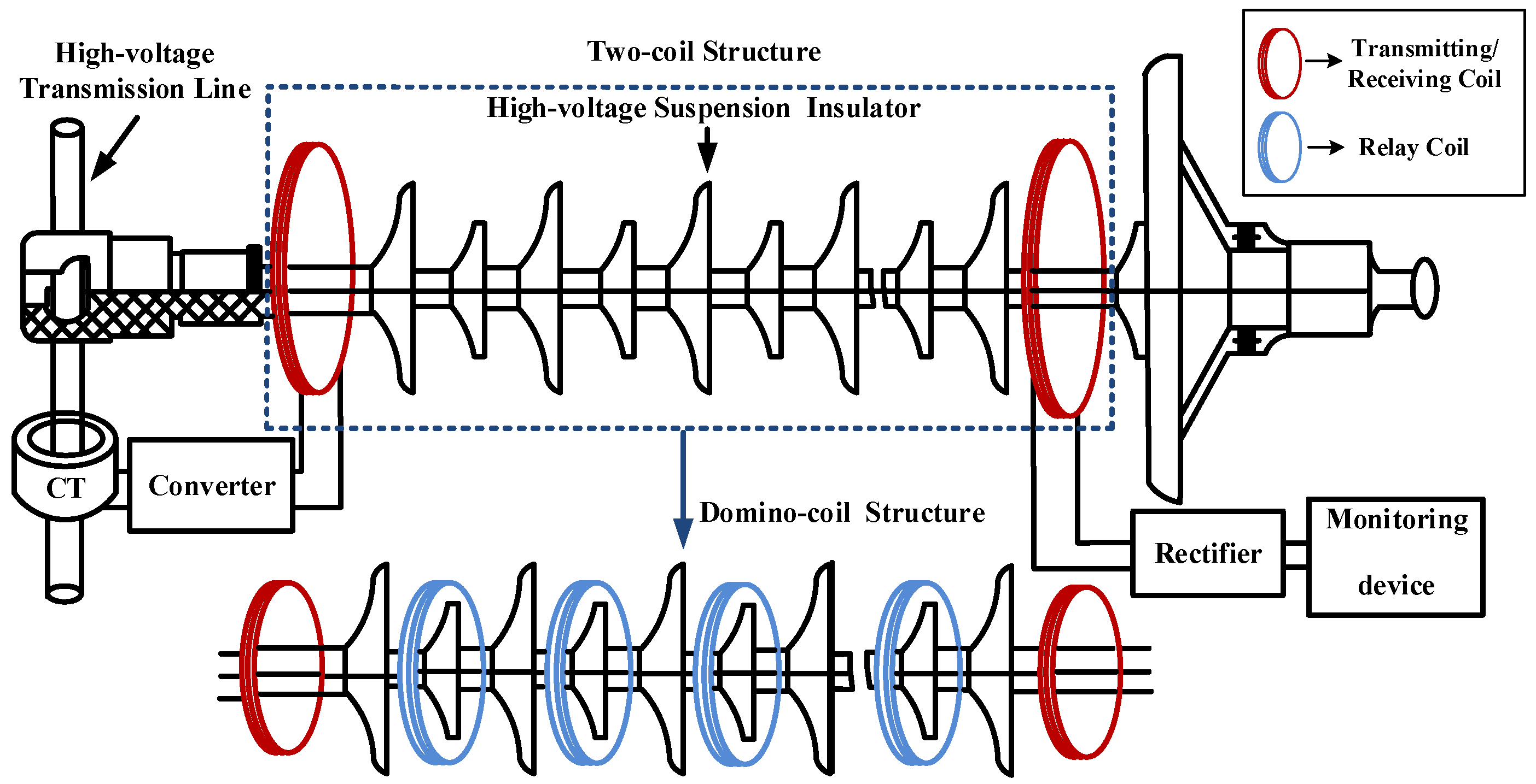
:1. Introduction
2. Review of Output Control Methods and Self-Oscillating Control Schemes
3. System Modeling and Analysis Method
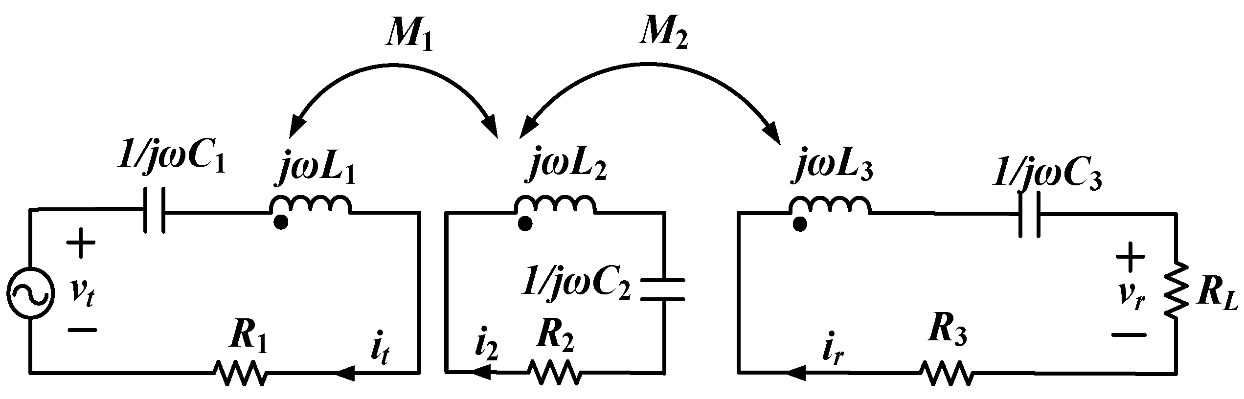
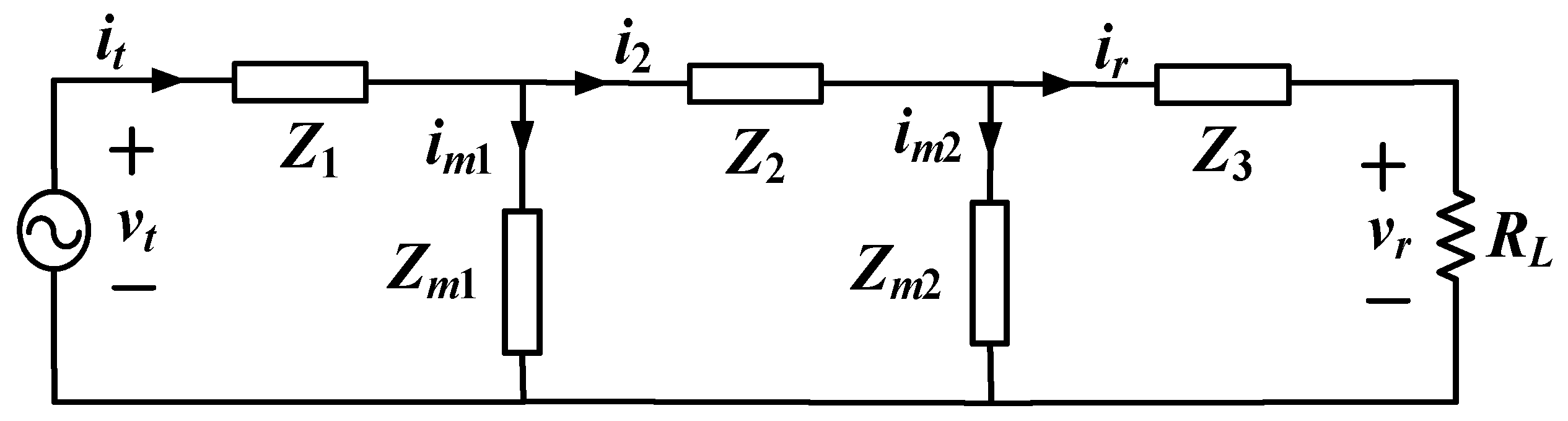
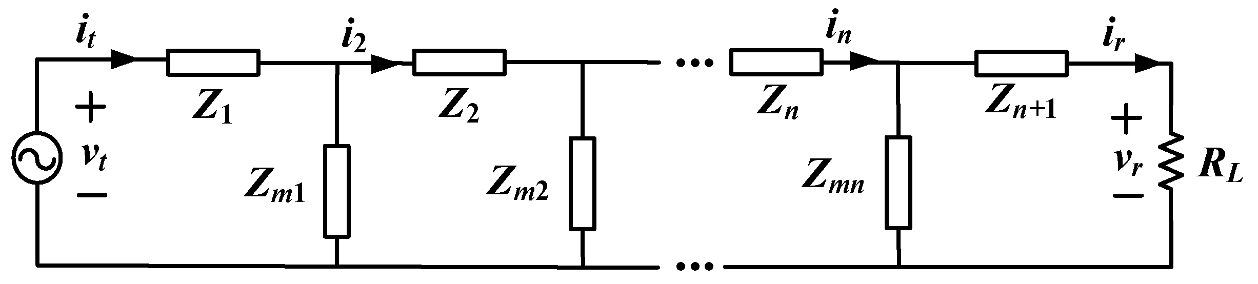
3.1. System Description of Three-Coil WPT Systems
3.2. Load-Independent Voltage Gain Characteristics
3.3. Load-Independent Frequency Prediction for N-Coil WPT Systems
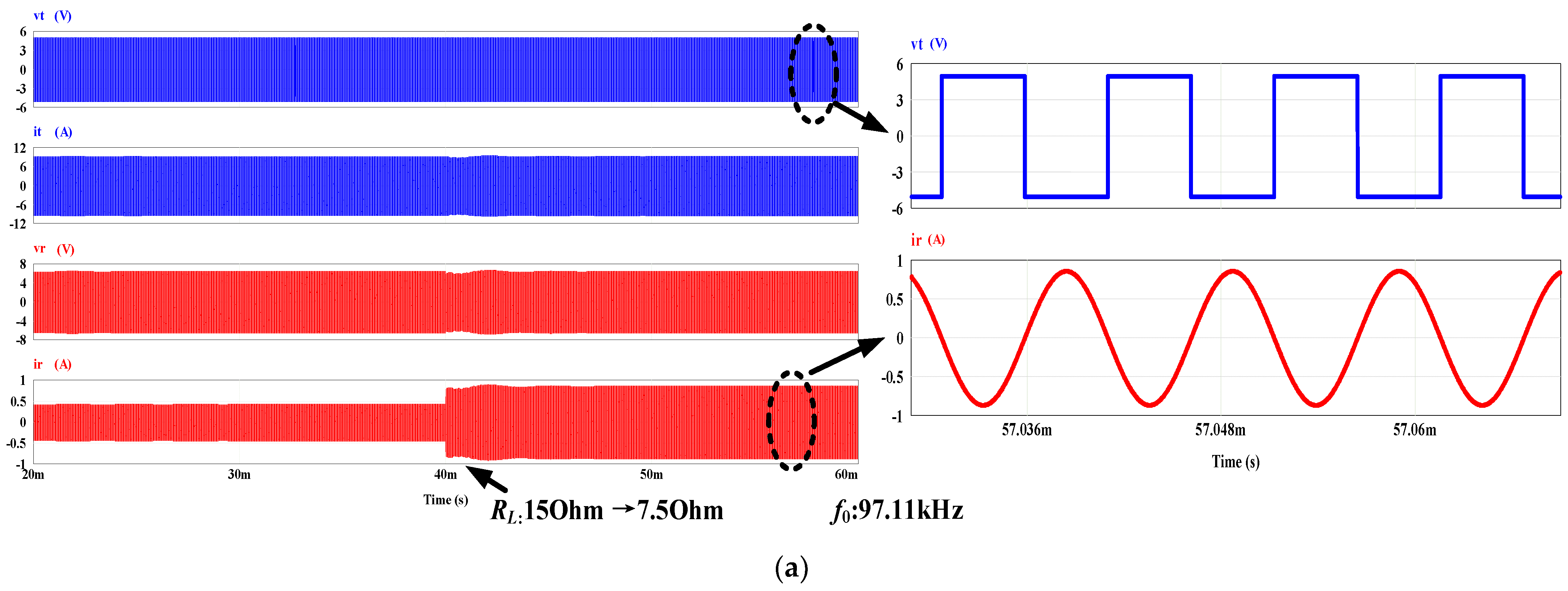
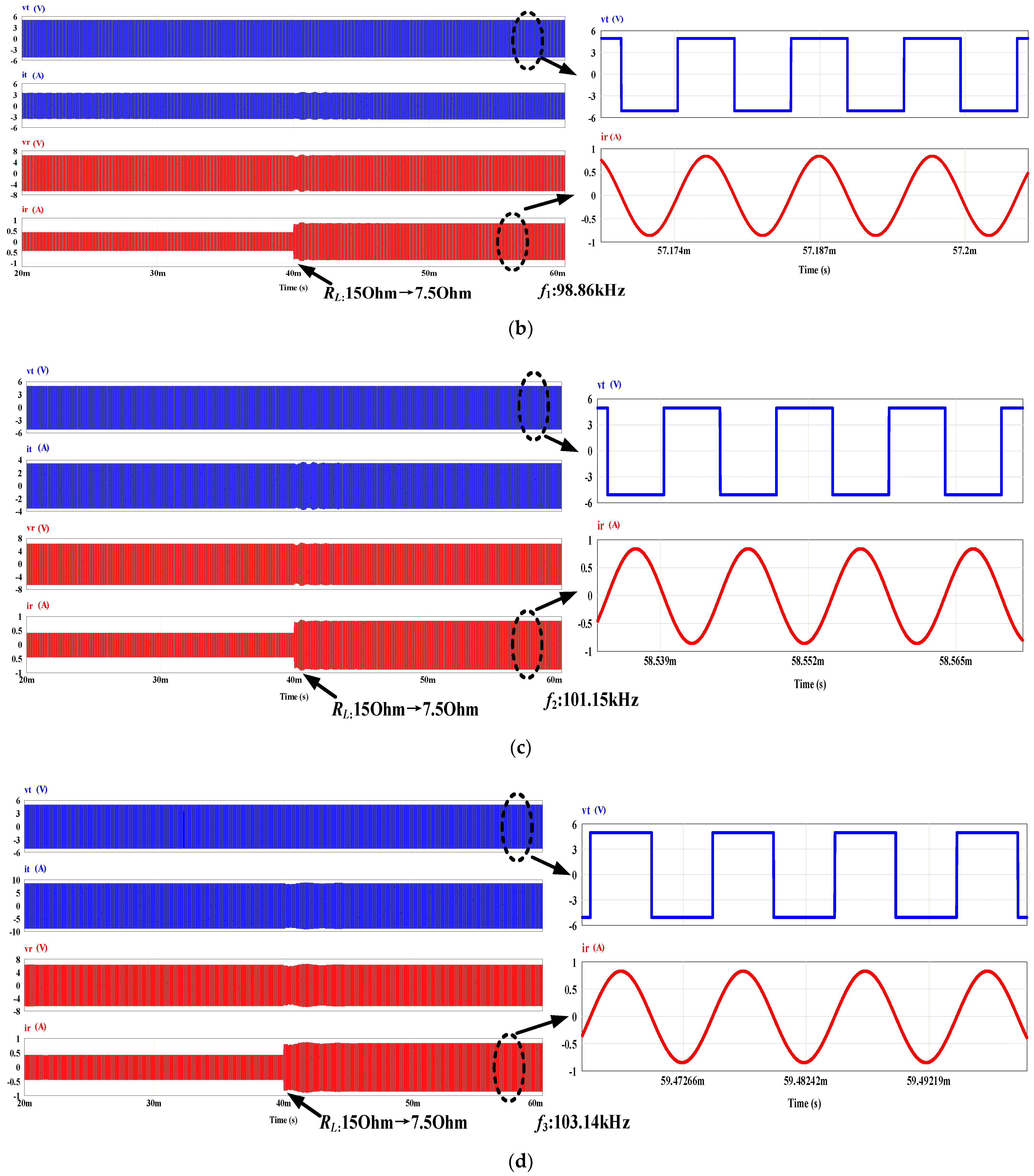
4. Simulation Verification
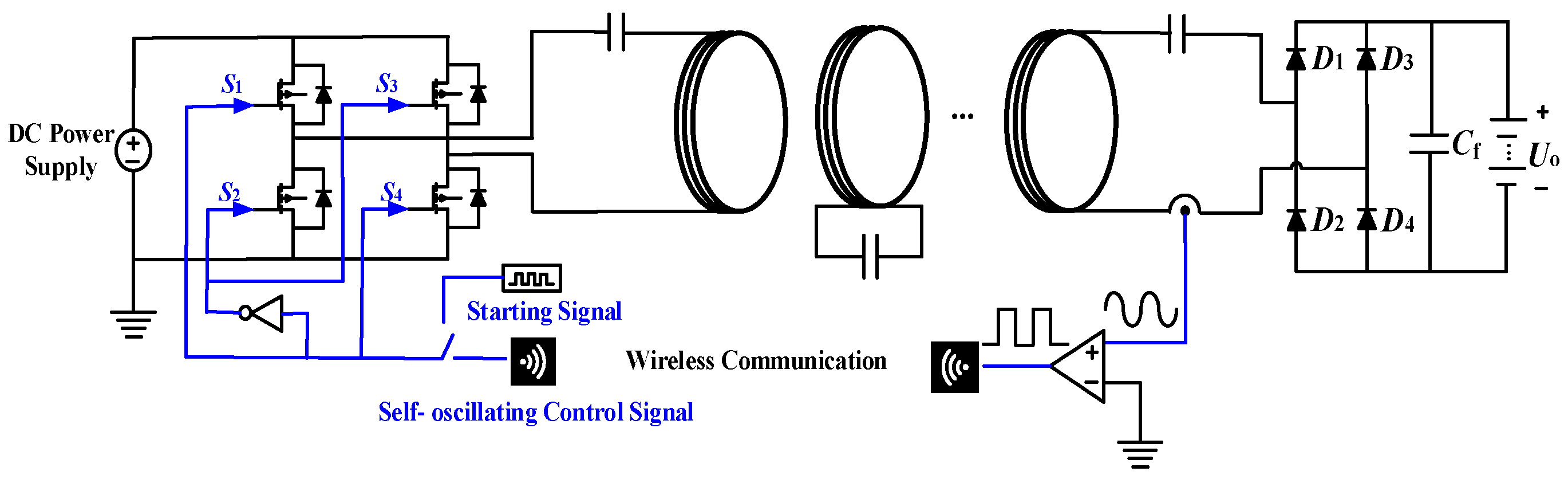
5. Experimental Verification
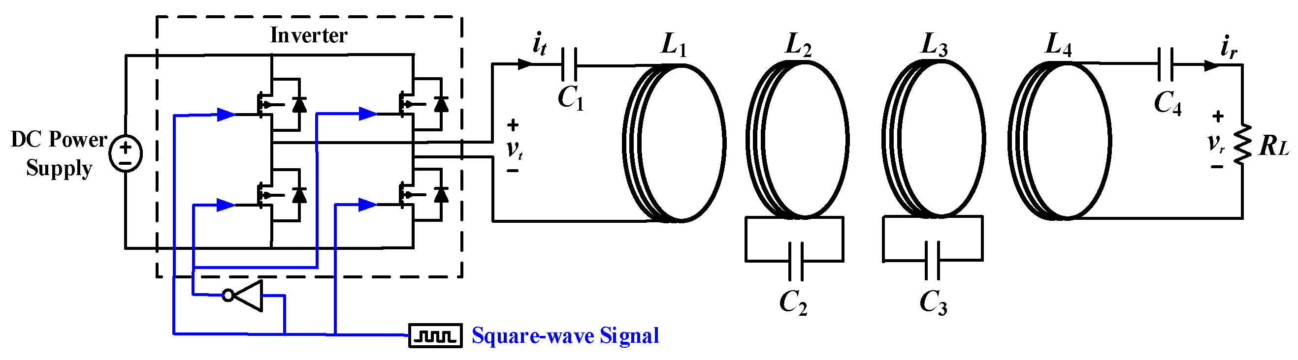
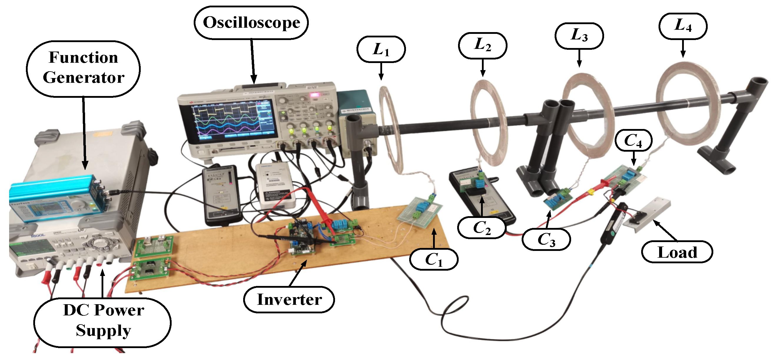
5.1. Experimental Setup
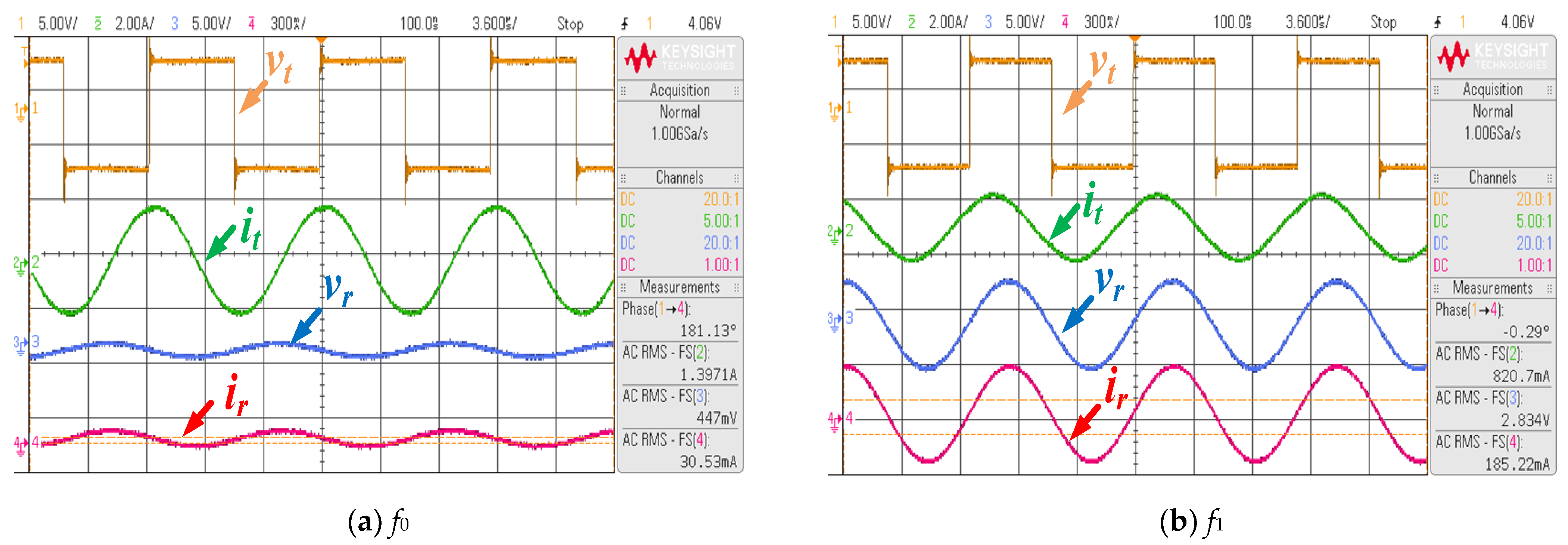
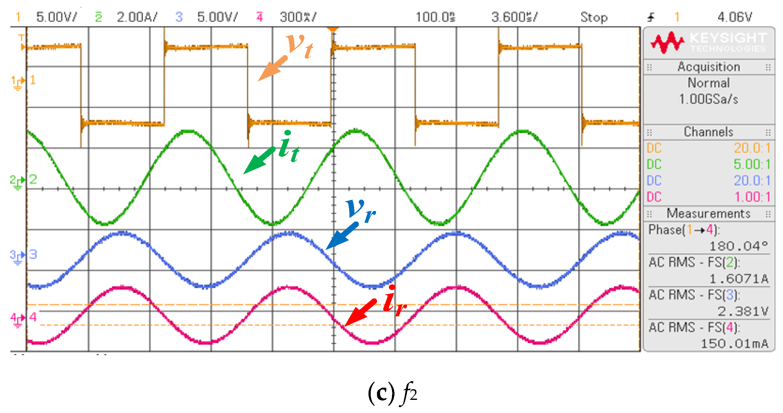
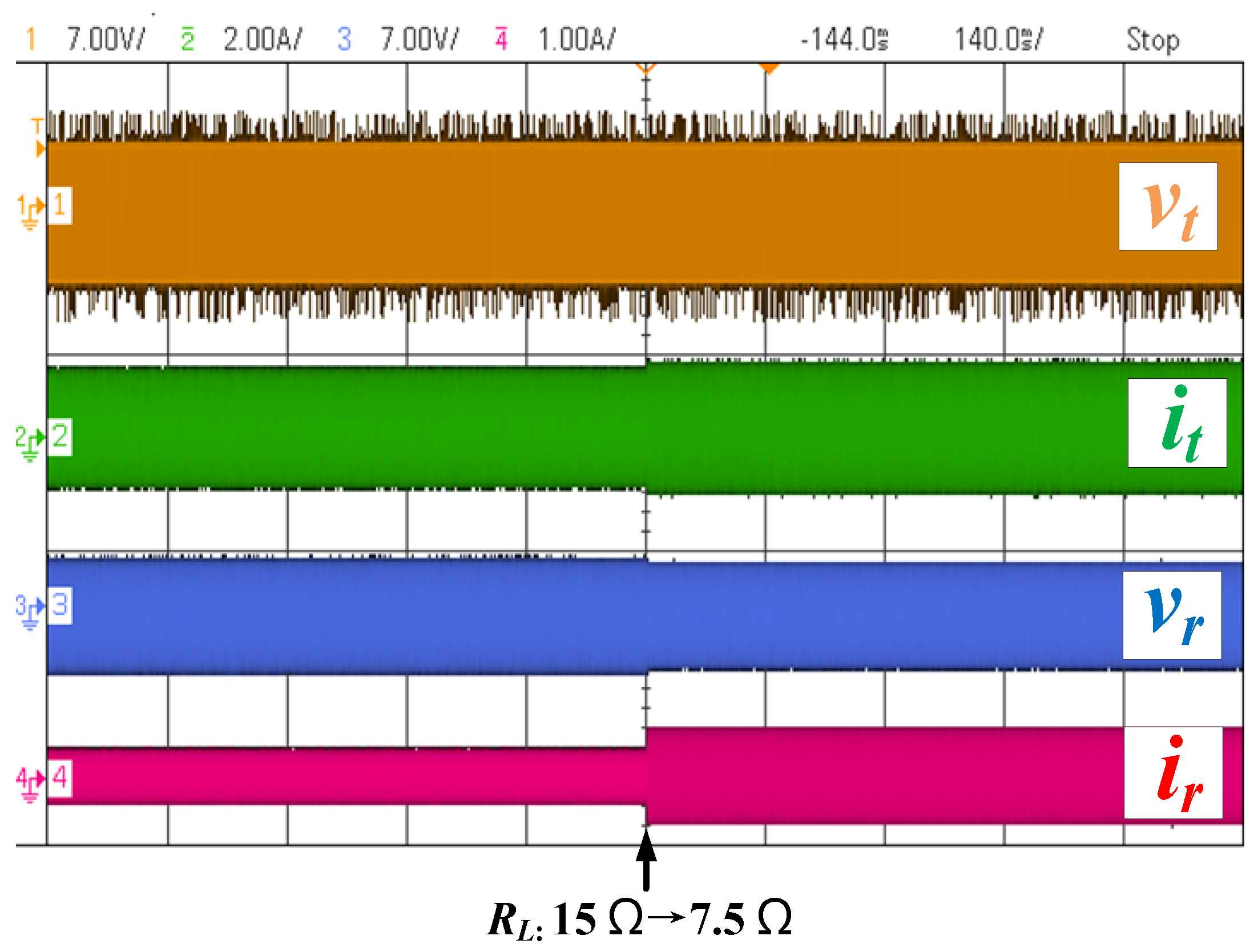
5.2. Experimental Results
6. Conclusions and Future Discussions
Author Contributions
Funding
Institutional Review Board Statement
Informed Consent Statement
Data Availability Statement
Conflicts of Interest
References
- Gouda, O.; Khalifa, D. On-Line Monitoring of High Voltage Transmission Line; Lambert Academic Publishing: Saarbrucken, Germany, 2012. [Google Scholar]
- Sun, X.; Huang, Q.; Jiang, L.J.; Pong, P.W.T. Overhead high-voltage transmission-line current monitoring by magnetoresistive sensors and current source reconstruction at transmission tower. IEEE Trans. Magn. 2014, 50, 4000405. [Google Scholar] [CrossRef] [Green Version]
- Ting, Y.; Xuanshu, C.; Du, Y.; Yejun, H. Research on power supply employed in ices real-time monitoring system of high-voltage transmission lines. In Proceedings of the International Conference on High Voltage Engineering and Application (ICHVE), Chongqing, China, 9–12 November 2008; pp. 626–628. [Google Scholar]
- Du, L.; Wang, C.; Li, X.; Yang, L.; Mi, Y.; Sun, C. A novel power supply of online monitoring systems for power transmission lines. IEEE Trans. Ind. Electron. 2010, 57, 2889–2895. [Google Scholar]
- Zhuang, Y.; Xu, C.; Song, C.; Chen, A.; Lee, W.; Huang, Y.; Zhou, J. Improving current transformer-based energy extraction from AC power lines by manipulating magnetic field. IEEE Trans. Ind. Electron. 2020, 67, 9471–9479. [Google Scholar] [CrossRef]
- Li, P.; Wen, Y.; Zhang, Z.; Pan, S. A high-efficiency management circuit using multi winding up conversion current transformer for powerline energy harvesting. IEEE Trans. Ind. Electron. 2015, 62, 6327–6335. [Google Scholar] [CrossRef]
- Zhang, J.; He, Z.; Liu, Y.; Luo, A.; Wang, L.; Wang, H.; Chen, Y.; Pang, Y. High-efficiency push-pull resonant converter solution for auxiliary power supply in 70-kV isolated applications. IEEE J. Emerg. Sel. Top. Power Electron. 2022, 10, 632–647. [Google Scholar] [CrossRef]
- Qu, J.; Lee, C.K. Dynamic modeling for the wireless power transfer system in domino structure. IEEE Trans. Ind. Electron. 2022, 69, 3556–3565. [Google Scholar] [CrossRef]
- Fang, Y.; Qu, J.; Pong, B.M.H.; Lee, C.K.; Hui, R.S.Y. Quasi-static modeling and optimization of two-layer PCB resonators in wireless power transfer systems for 110-kV power grid online monitoring equipment. IEEE Trans. Ind. Electron. 2022, 69, 1400–1410. [Google Scholar] [CrossRef]
- Wu, N.; Xiao, J.; Han, S.; Zhang, L.; Chen, L. Insulation analysis of high-voltage transmission line insulator with embedded wireless power transfer coils. In Proceedings of the IEEE 2nd China International Youth Conference on Electrical Engineering (CIYCEE), Chengdu, China, 15–17 December 2021; pp. 1–5. [Google Scholar]
- Lomas, R. The Man Who Invented the Twentieth Century—Nikola Tesla—Forgotten Genius of Electricity; Headline Book Publishing Ltd.: London, UK, 1999; p. 146. [Google Scholar]
- Tesla, N. Apparatus for Transmitting Electrical Energy. U.S. Patent 1,119,732, 1 December 1914. [Google Scholar]
- Zhong, W.; Lee, C.K.; Hui, S.Y.R. General analysis on the use of Tesla’s resonators in domino forms for wireless power transfer. IEEE Trans. Ind. Electron. 2013, 60, 261–270. [Google Scholar] [CrossRef] [Green Version]
- Choi, B.H.; Thai, V.X.; Lee, E.S.; Kim, J.H.; Rim, C.T. Dipole-Coil-based wide-range inductive power transfer systems for wireless sensors. IEEE Trans. Ind. Electron. 2016, 63, 3158–3167. [Google Scholar] [CrossRef]
- Hui, S.Y.R.; Zhong, W.; Lee, C.K. A critical review of recent progress in mid-range wireless power transfer. IEEE Trans. Power Electron. 2014, 29, 4500–4511. [Google Scholar] [CrossRef] [Green Version]
- Lee, C.K.; Zhong, W.X.; Hui, S.Y.R. Effects of magnetic coupling of nonadjacent resonators on wireless power domino-resonator systems. IEEE Trans. Power Electron. 2012, 27, 1905–1916. [Google Scholar] [CrossRef] [Green Version]
- Zhong, W.X.; Lee, C.K.; Hui, S.Y. Wireless power domino-resonator systems with noncoaxial axes and circular structures. IEEE Trans. Power Electron. 2012, 27, 4750–4762. [Google Scholar] [CrossRef] [Green Version]
- Feng, J.; Li, Q.; Lee, F.C. Load detection and power flow control algorithm for an omnidirectional wireless power transfer system. IEEE Trans. Ind. Electron. 2022, 69, 1422–1431. [Google Scholar] [CrossRef]
- Kurs, A.; Karalis, A.; Moffatt, R.; Joannopoulos, J.D.; Fisher, P.; Soljačić, M. Wireless power transfer via strongly coupled magnetic resonances. Science 2007, 317, 83–86. [Google Scholar] [CrossRef] [Green Version]
- Dong, Z.; Liu, S.; Li, X.; Xu, Z.; Yang, L. A novel long-distance wireless power transfer system with constant current output based on domino-resonator. IEEE J. Emerg. Sel. Top. Power Electron. 2021, 9, 2343–2355. [Google Scholar] [CrossRef]
- Cheng, C.; Li, W.; Zhou, Z.; Deng, Z.; Mi, C. A load-independent wireless power transfer system with multiple constant voltage outputs. IEEE Trans. Power Electron. 2020, 35, 3328–3331. [Google Scholar] [CrossRef]
- Cheng, C.; Zhou, Z.; Li, W.; Deng, Z.; Mi, C.C. A power relay system with multiple loads using asymmetrical coil design. IEEE Trans. Power Electron. 2021, 68, 1188–1195. [Google Scholar] [CrossRef]
- Chen, T.; Cheng, C.; Cheng, H.; Wang, C.; Mi, C.C. A multi-load capacitive power relay system with load-independent constant current outputs. IEEE Trans. Power Electron. 2022, 37, 6144–6155. [Google Scholar] [CrossRef]
- Cai, C.; Wang, J.; Liu, R.; Fang, Z.; Zhang, P.; Long, M.; Hu, M.; Lin, Z. Resonant wireless charging system design for 110-kV high-voltage transmission line monitoring equipment. IEEE Trans. Ind. Electron. 2019, 66, 4118–4129. [Google Scholar] [CrossRef]
- Huang, X.; Yan, C.; Wang, W.; Zhao, J.; Tan, L. Hybrid wireless charging system for monitoring overhead 110 kV high-voltage power line equipment based on magneto-electric conversion. IET Gener. Transm. Distrib. 2016, 10, 1199–1208. [Google Scholar]
- Syms, R.; Shamonina, E.; Kalinin, V.; Solymar, L. A theory of metamaterials based on periodically loaded transmission lines: Interaction between magneto-inductive and electromagnetic waves. J. Appl. Phys. 2005, 97, 064909. [Google Scholar] [CrossRef] [Green Version]
- Zhou, H.; Gao, X.; Lai, J.; Hu, W.; Deng, Q.; Zhou, D. Natural frequency optimization of wireless power systems on power transmission lines. IEEE Access 2018, 6, 14038–14047. [Google Scholar] [CrossRef]
- Yan, Z.; Xie, H.; Li, Y.; He, Z.; Yang, H.; Zhou, W.; Zhu, C.; Jing, X.; Chen, S.; Mai, R. A Monitoring Equipment Charging System for HVTL Based on Domino-Resonator WPT With Constant Current or Constant Voltage Output. IEEE Trans. Power Electron. 2022, 37, 3668–3680. [Google Scholar] [CrossRef]
- Yang, Y.; Zhong, W.; Kiratipongvoot, S.; Tan, S.; Hui, S. Dynamic improvement of series-series compensated wireless power transfer systems using discrete sliding mode control. IEEE Trans. Power Electron. 2018, 33, 6351–6360. [Google Scholar] [CrossRef]
- Li, H.; Li, J.; Wang, K.; Chen, W.; Yang, X. A maximum efficiency point tracking control scheme for wireless power transfer systems using magnetic resonant coupling. IEEE Trans. Power Electron. 2015, 30, 3998–4008. [Google Scholar] [CrossRef]
- Yang, Y.; Qin, Y.; Tan, S.C.; Hui, S.Y.R. Efficient improvement of photovoltaic-battery systems in standalone DC microgrids using a local hierarchical control for the battery system. IEEE Trans. Power Electron. 2019, 34, 10796–10807. [Google Scholar] [CrossRef]
- Yao, Y.; Wang, Y.; Cheng, H.; Lu, K.; Guan, Y.; Gao, S.; Liu, X.; Xu, D. A variable frequency control (VFC)-based WPT system featuring constant voltage output, less power stages, and lower system costs. In Proceedings of the 2019 22nd International Conference on Electrical Machines and Systems (IC2019 22nd International Conference on Electrical Machines and Systems (ICEMS), Harbin, China, 11–14 August 2019; pp. 1–5. [Google Scholar]
- Guidi, G.; Suul, J.A. Minimizing converter requirements of inductive power transfer systems with constant voltage load and variable coupling conditions. IEEE Trans. Ind. Electron. 2016, 63, 6835–6844. [Google Scholar] [CrossRef] [Green Version]
- Gati, E.; Kampitsis, G.; Stavropoulos, I.; Papathanassiou, S.; Manias, S. Wireless phase-locked loop control for inductive power transfer systems. In Proceedings of the 2015 IEEE Applied Power Electronics Conference and Exposition (APEC), Charlotte, NC, USA, 15–19 March 2015. [Google Scholar]
- Wang, X.; Liu, S.; Li, Q.; Xu, H. Self-oscillating control method and topology analysis for parallel resonant contactless power transfer systems. In Proceedings of the 2017 IEEE PELS Workshop on Emerging Technologies: Wireless Power Transfer (WoW), Chongqing, China, 20–22 May 2017. [Google Scholar]
- Yan, K.; Chen, Q.; Hou, J.; Ren, X.; Ruan, X. Self-oscillating contactless resonant converter with phase detection contactless current transformer. IEEE Trans. Power Electron. 2014, 29, 4438–4449. [Google Scholar] [CrossRef]
- Xu, L.; Chen, Q.; Ren, X.; Wong, S.; Tse, C.K. Self-oscillating resonant converter with contactless power transfer and integrated current sensing transformer. IEEE Trans. Power Electron. 2017, 32, 4839–4851. [Google Scholar] [CrossRef]
- Ren, X.; Chen, Q.; Cao, L.; Ruan, X.; Wong, S.C.; Tse, C.K. Characterization and control of self-oscillating contactless resonant converter with fixed voltage gain. In Proceedings of the 7th International Power Electronics and Motion Control Conference, Harbin, China, 2–5 June 2012. [Google Scholar]
- Cheng, C.; Zhou, Z.; Li, W.; Zhu, C.; Deng, Z.; Mi, C.C. A multi-load wireless power transfer system with series-parallel-aeries compensation. IEEE Trans. Power Electron. 2019, 34, 7126–7130. [Google Scholar] [CrossRef]
- Wang, Y.; Dongye, Z.; Kheirollahi, R.; Zhang, H.; Zheng, S.; Lu, F. Review of load-independent constant-current and constant-voltage topologies for domino-type multiple-load inductive power relay system. IEEE J. Emerg. Sel. Top. Power Electron. 2022, 3, 199–210. [Google Scholar] [CrossRef]
- Dongye, Z.; Wang, Y.; Zhao, S.; Zhang, H.; Lu, F. A π-type compensated ferrite-free domino IPT system for DC circuit breakers. IEEE Trans. Power Electron. 2022, 37, 7518–7527. [Google Scholar] [CrossRef]


| Name | Value |
|---|---|
| Input voltage (Vdc) | 5 V |
| Self-inductance (Li) | 49.2 µH |
| Compensated capacitance (Ci) | 51.5 nF |
| Mutual inductance (Mi) | 1.83 µH |
| Load resistance (RL) | |
| Resonant frequency | 100 kHz |
| Symbol | Value | Symbol | Value |
|---|---|---|---|
| Vdc | 5 V | R3 | 0.3 Ω |
| L1 | 49.2 µH | L4 | 49.18 µH |
| C1 | 51.58 nF | C4 | 51.5 nF |
| R1 | 0.3 Ω | R4 | 0.3 Ω |
| L2 | 49.16 µH | M1 | 1.83 µH |
| C2 | 51.52 nF | M2 | 1.79 µH |
| R2 | 0.3 Ω | M3 | 1.77 µH |
| L3 | 49.22 µH | RL | 15 Ω |
| C3 | 51.6 nF |
| f0 | f1 | f2 | ||||
|---|---|---|---|---|---|---|
| Frequency (kHz) | Calculated | Measured | Calculated | Measured | Calculated | Measured |
| 97.42 | 96.24 | 98.96 | 99.21 | 102.85 | 102.20 | |
| Voltage gain | 0.16 | 0.11 | 0.70 | 0.64 | 0.59 | 0.55 |
| Vt (RMS) | It (RMS) | Vr (RMS) | Ir (RMS) | Pout | η | |
|---|---|---|---|---|---|---|
| RL= 15 Ω | 4.39 V | 0.83 A | 2.83 V | 0.19 A | 0.54 W | 15% |
| RL′ = 7.5 Ω | 4.40 V | 0.91 A | 2.69 V | 0.36 A | 0.97 W | 24% |
Publisher’s Note: MDPI stays neutral with regard to jurisdictional claims in published maps and institutional affiliations. |
© 2022 by the authors. Licensee MDPI, Basel, Switzerland. This article is an open access article distributed under the terms and conditions of the Creative Commons Attribution (CC BY) license (https://creativecommons.org/licenses/by/4.0/).
Share and Cite
Wang, K.; Liang, R.; Yang, Y. A Load-Independent Self-Oscillating Control of Domino Wireless Power Transfer Systems for High-Voltage Power Grid Monitoring Equipment. Energies 2022, 15, 4228. https://doi.org/10.3390/en15124228
Wang K, Liang R, Yang Y. A Load-Independent Self-Oscillating Control of Domino Wireless Power Transfer Systems for High-Voltage Power Grid Monitoring Equipment. Energies. 2022; 15(12):4228. https://doi.org/10.3390/en15124228
Chicago/Turabian StyleWang, Kaiyuan, Rui Liang, and Yun Yang. 2022. "A Load-Independent Self-Oscillating Control of Domino Wireless Power Transfer Systems for High-Voltage Power Grid Monitoring Equipment" Energies 15, no. 12: 4228. https://doi.org/10.3390/en15124228