1. Introduction
In the 1960s and 1970s, due to the underdeveloped production technology of China’s coal mines, in order to avoid the mutual influence of mining and tunneling, the panel in the mining area in some mines adopts the methods of jumping mining and cross-mining, which make it easy to form one side, two ribs, or even four sides of the gob panel—that is, the isolated panel [
1]. In addition, due to the unreasonable early mine planning, most old mines in China have the problem of irregular gob in the recovery of protective coal pillars. In the recovery of isolated coal pillars under irregular gob, the distribution regularity of abutment pressure is quite different from the general mining of isolated coal faces, and the overburden movement is more complex.
In the past half-century, many scholars have conducted a lot of research on the overburden movement regularity and ground pressure characteristics of isolated panels. Li [
2] conducted optimization research on the coal pillar of an isolated coal pillar panel formed by upper and lower layers, according to the status of the deep isolated mining panel. Cheng [
3] divided a gob-side roadway into three areas according to the distance from the panel. Wang [
4] found that having a reasonable coal pillar size of the gob-side roadway in an isolated face can not only prevent dynamic disasters in the excavation process, but also improve the utilization rates of resources. Shan and Zhang [
5,
6] constructed a mechanical model of “gob-coal pillar-roadway-solid coal” at the position of a gob-side roadway. Zhao [
7] studied the stress distribution and prevention of rock burst during isolated panel mining under irregular remaining coal pillars. Gu [
8] studied the internal strength of triangular coal pillars in the process of panel mining, and analyzed the strength changes of triangular coal pillars during panel mining. Jiang [
9] studied the evolution regularity of a roof structure with irregular gob on both sides, and put forward the risk assessment of impact instability of isolated panels in irregular gob. At present, there are many pieces of research on stress distribution and measures for the prevention of rock burst for regular coal pillar gob-side roadways in isolated panels [
10,
11,
12]. There are few studies on the distribution of irregular abutment pressure in irregular gob and pillars.
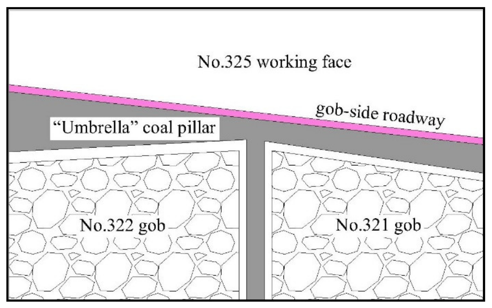
Taking Yangcun Coal Mine as the engineering background, according to the actual geological conditions of headentry in isolated panel No. 325, panel No. 325 was selected to pass through the gob of No. 321 and No. 322. The two gobs are located on the same side of panel No. 325, and are vertically distributed with panel No. 325. In addition, the coal pillars between panel No. 325 and the gob of No. 321 and No. 322 are in an “umbrella” shape. This coal pillar shape is special, and its width varies greatly. The study of the stress distribution regularity of the gob-side roadway along the isolated panel under this type of coal pillar is actually a study of the mechanical structure of irregular gob.
2. Engineering Background
The No. 3 coal seam is mined in panel No. 325 of Yangcun Coal Mine, with an average dip angle of 4°, which is near-horizontal coal seam. The average thickness of a coal seam is 8.13 m, and the thickness in most sections is above 8 m. The direct roof of the No. 3 coal seam is mainly siltstone and sandy mudstone, with a general thickness of 0.35~11.36 m. The main roof is mainly medium-to-fine sandstone, with relatively developed fractures and a partial false roof. The direct bottom is siltstone or mudstone, and the main floor is medium-to-fine sandstone or siltstone.
The next section of panel No. 325 consists of five gobs. The specific distribution is shown in
Figure 1. Among them, gobs No. 319, No. 320, and No. 324, along with panel No. 325, form irregular coal pillars, which can be approximately regarded as “T”-type coal pillars. This type of coal pillar has been analyzed in detail in the literature [
7]. Meanwhile, gobs No. 321 and No. 322, along with panel No. 325, form special “umbrella”-type coal pillars, as shown in
Figure 2. There is a great difference between the “umbrella”-type and “T”-type coal pillars in terms of the stress distribution and migration of the surrounding rock. Hence, the stress state, stress distribution regularity, and break characteristics of the surrounding rock are comprehensively analyzed in this paper.
3. Mechanical Analysis of Irregular “Umbrella” Coal Pillars
3.1. Mechanical State Analysis of Coal Pillar
According to the key strata theory of the academic Qian [
13], after the panel is pushed and mined, a small structure composed of key blocks A, B, and C is formed in the gob-side roadway of the panel, as shown in
Figure 3. In
Figure 3,
m is the coal thickness (m),
n is the direct roof thickness (m),
x1 is the width of the coal pillar (m),
x2 is the width of the roadway (m),
x3 is the distance between the fault position of key block B and the left boundary of the roadway (m), and
l is the length of key block B (m). Key block B’s length (
l) is equal to the periodic weighting interval of the mining face.
η1 is the stiffness coefficient in the vertical direction of the direct roof,
η2 is the stiffness coefficient in the vertical direction of the coal pillar, and Δ
s is the sink amount of key block B (m).
Zhang Yang and Yang Yongjie, the authors of this paper, carried out mechanical analysis of the gob-side roadway coal pillar in goaf in [
14]:
where
p is the pressure acting on the coal pillar;
E1 and
E2 are the elastic modulus of the immediate roof and the coal pillar, respectively (MPa);
A is the side-pressure coefficient;
α is the angle of internal friction;
k is the direct roof-bursting coefficient;
γ is the gravity density of the strata (kN/m
3);
H is the mining depth (m);
C0 is the cohesion at the junction between the coal seam and the roof and floor;
Px is the prestressing force of the roof bolting (kN); and
M is the mining height (m). In this paper, coal thickness is equal to mining height (
m =
M).
As for the “umbrella” coal pillar in this paper, the key blocks A, B, and C form an arcing triangular block structure above the coal pillar. When panel No. 325 passes through mined-out areas No. 321 and No. 322, due to the irregular shape of the mined-out areas, x1 first decreases and then increases. When x1 decreases to a certain range, the coal pillar is subjected to the maximum pressure when it just enters mined-out area No. 321 and is about to pass through mined-out area No. 322. Therefore, it can be inferred that this area is prone to roof collapse, deviation, and even rock-burst disasters.
3.2. Abutment Pressure Distribution Regularity of Irregular Coal Pillars
3.2.1. Abutment Pressure Distribution Regularity at the Irregular Coal Pillar Edge
After stoping the panel, the stress state of the gob roof changes from three-way stress to bidirectional stress, and the stress of the gob roof is redistributed [
15]; the roof strata rotate and sink under the action of stress, and then cause extrusion and damage to the residual coal pillar, resulting in the reduction in the physical properties of the residual coal pillar and the reduction in the bearing capacity. At the same time, by applying beam theory [
16,
17], the abutment pressure in gob is transferred to the internal section of solid coal along the unbroken strata of the roof.
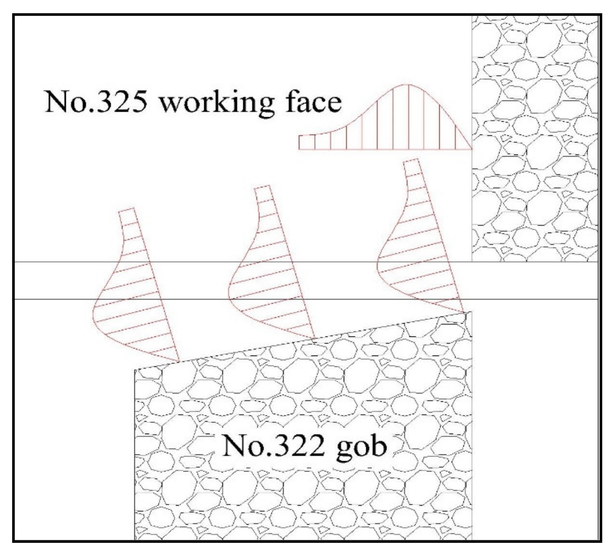
There have been few previous studies on irregular coal pillars caused by irregular gob, and most studies take regular coal pillars as an example. Under the regular rectangular pillar [
18], the edge of the gob is parallel to the gob-side roadway, and the abutment pressure of the gob is transferred vertically to the internal part of the unmined solid coal. However, in this paper, taking gob No. 322 as an example, the stop-mining line of gob No. 322 crosses diagonally with the gob-side roadway and panel No. 322 after mining; a series of strata movements such as fracture, rotation, and subsidence occur in key blocks, and the fracture line of the key blocks is parallel to the direction of the stop-picking line. The distribution direction of abutment pressure of gob No. 322 is shown in
Figure 4. It should be distributed along the direction perpendicular to the stop-production line, as shown in
Figure 5.
3.2.2. Abutment Pressure Distribution Rules at Irregular Coal Pillar Fracture Points
Take gob No. 322 as an example, after the completion of panel No. 322, its roof breaks along the stop-production line, and a small structure composed of key blocks A, B, and C is formed by rotary subsidence. Key block B is the main part of the coal pillar, so mechanical analysis of key block B was carried out. In general studies, because the gob is generally distributed parallel to the gob-side roadway, only the vertical direction was considered in the analysis of key block B. However, in this paper, the angle α is generated between key block B and the surrounding roof strata that did not break. Hence, it is necessary to conduct a mechanical analysis of key block B in the vertical and horizontal directions.
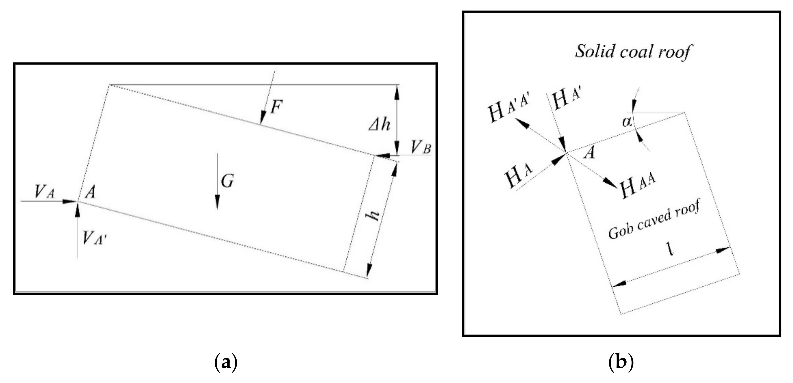
In
Figure 6, F is the load of the overburden, Δ
H is the collapse height,
VA and
VB are horizontal thrust,
VA′ is the supporting force of the coal pillar,
G is the dead weight of the key block,
h is the thickness of the key block,
l is the horizontal length of the key block,
α is the included angle between the key block and the gob,
HA and
HA′ are the extrusion pressure of non-caving rock strata on key block B in the horizontal direction,
HAA is the resultant force of
HA and
HA′, and
HA′A′ is the counteracting force of
HAA.According to the elastic equilibrium equation
,
is found by the following formula [
19]:
As can be seen from
Figure 6b, when key block B rotates and sinks, the force
on the unbroken roof strata is in the opposite direction to the gob bisector.
4. Numerical Simulation Analysis of an Irregular “Umbrella” Coal Pillar on a Gob-Side Roadway in an Isolated Panel
4.1. Establishment of Numerical Model
The model size was 200 m × 150 m × 70 m, and there were eight strata of rock. The detailed mechanical parameters of each rock stratum are shown in
Table 1. Horizontal constraints were imposed on the four boundaries to limit the vertical displacement at the bottom. The bottom was a fixed boundary to limit the horizontal and vertical displacement at the bottom. The gravity overburden of 3.5 MPa was applied on the upper boundary of the model, and the attached statement was used to connect the mesh size. The model adopted the Mohr–Coulomb criterion. The FLAC3D model is shown in
Figure 7.
In the simulation calculation, the attributes of each rock stratum, the dead weight, and the pressure on the top surface of the model are loaded first, and the initial equilibrium is calculated, in strict accordance with the scenario of the actual mining order. First of all, the excavation of panel No. 321, using the hulking coefficient and physical and mechanical characteristics of the elastic material filling the gob, along with calculation of balance, record the corresponding data as the initial values. After excavation of panel No. 322, the same calculation is performed for balance and finally, in panel No. 325, for mining work and to calculate balance.
4.2. Stress Analysis of Surrounding Rock during Gob-Side Roadway Excavation
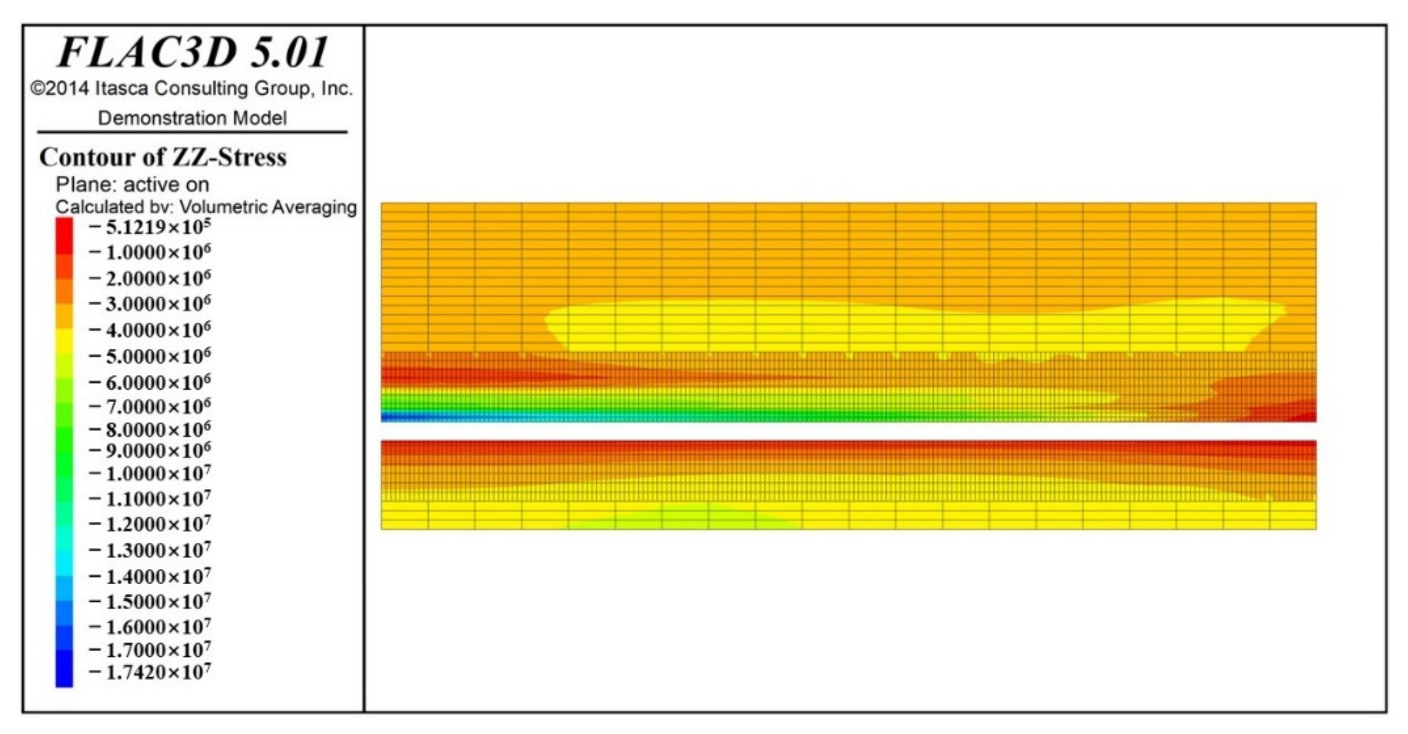
Figure 8 shows the vertical stress diagram of the whole roof and floor of the gob-side roadway in the mining front of panel No. 325. It can be seen from the figure that the broken depth of the floor increases gradually from the middle of the model to both ends due to the lack of protection measures in the roadway floor, from 1 m in the middle to 2 m at both ends. At the same time, the vertical stress of the roadway roof shows the same variation trend as that of the floor. The vertical stress of the roof extends from 7 MPa in the middle to 17 MPa on the left and 0.5 MPa on the right, indicating that the roof has a plastic break.
The gob-side roadway in
Figure 9 shows a roadway waistline after the “umbrella” model; when the coal pillar and roof have a 2.5 m floor plan, the scope of the vertical stress can be seen in
Figure 9a. While passing through gob No. 321, time as the coal pillar width increases, the surrounding rock stress near the roadway also increases, but has not yet reached peak position, while the vertical stress of the surrounding rock is relatively complete. When the gob-side roadway passes through gob No. 322, as the width of the coal pillar increases from 8 m to 20 m—and especially when it increases to 15 m—the stress concentration phenomenon occurs inside the coal pillar, and the vertical stress of the rib of the roadway coal pillar is less than the original rock stress, indicating that the plastic break of the rib of the coal pillar occurs under the action of high stress. It can be seen from
Figure 9b–d that the roof stress of the gob-side roadway reaches its peak at 1.5 m, and then decreases with the increase in height.
It is important to note that when the gob-side roadway passes through the 4 m protective coal pillar in gobs No. 321 and No. 322, the coal side of the roadway produces a wide range of abutment pressure areas. It is shown in
Figure 9 that there is a wavy stress region in panel No. 325, where the maximum stress is 6 MPa. This shows that the coal pillar roof between the two gobs is relatively intact. During the stress redistribution of gobs No. 321 and No. 322 under the influence of the gob-side roadway, the abutment pressure is transmitted to the solid coal side of the goaf through the unbroken rock strata of the 4 m coal pillar roof. This has little influence during roadway excavation, but the influence of pressure superposition on the roadway must be considered.
From the analysis of the mathematical model given in
Section 3.2 and the results of numerical simulation, we can speculate that during the actual production process, there is a possibility that the stress concentration area will appear in the surrounding rock of the roadway after the gob or before the gob. If this is not understood properly, the roof or the two ribs of the roadway can easily cave in.
4.3. Analysis of Surrounding Rock Stress and Deformation during Mining
Figure 10 shows the distribution of vertical stress on the panel at different mining locations and 1.5 m above the roadway roof in the process of mining panel No. 325. During the stoping of face No. 325, the abutment pressure of gob No. 321 and the advanced abutment pressure of the panel are superimposed in front of the panel, and the stress above the roadway roof here is 8 MPa. However, as the width of the coal pillar in front of the panel decreases, the superposition area gradually expands to the top of the roadway roof, and the vertical stress above the roof increases to 9 MPa.
Figure 10b shows the position of 80 m in the mining panel. At this time, the advanced abutment pressure of the panel is symmetrically distributed, with a 4 m protective coal pillar between gobs No. 321 and No. 322, which has a great influence on the solid coal rib of the gob-side roadway.
Figure 10c,d show the vertical stress distribution diagrams when the panel passes through the position of gob No. 322. It can be seen that with the increase in the width of the mining panel and coal pillar, the vertical stress above the roadway roof decreases from 12 MPa to 10 MPa, but the vertical stress within the coal pillar increases from 9 MPa to 11 MPa, which is consistent with the results of numerical simulation. As the coal pillar increases from 8 m to 20 m, the abutment pressure of gob No. 322 transfers to the interior of the coal pillar, and the effect of stress superposition inside the solid coal is weakened. At this time, the lateral stress of the roadway coal pillar is greater than that of the solid coal side.
In order to attain a clearer understanding of the stability of the surrounding rock of the gob-side roadway in the stoping process of panel No. 325, the deformation of the surrounding rock of the gob-side roadway during stoping was statistically analyzed and compared with the above surrounding rock stress. The curve of surrounding rock movement of the gob-side roadway within 20 m in advance during stoping of the panel is shown in
Figure 11.
It can be seen from the figure that when the panel passes through gob No. 321, the subsidence of the roadway roof decreases with the decrease in the coal pillar’s size, and until it reaches the minimum value when it passes through the coal pillars between the two gobs. When the panel passes through gob No. 322, the subsidence of the roadway roof first increases and then decreases with the increase in coal pillar size.
In contrast to the previous analysis, although the vertical stress within the coal pillar between the gob-side roadway and gob No. 322 increases continuously, the increase in the lateral wall movement of the solid coal is small, and the surrounding rock movement is about 200 mm, indicating that the stress concentration area is far from the ribs, and that the surrounding rock of the rib of the gob is relatively intact. The sidewall movement of solid coal in the gob-side roadway changes obviously with the size of the coal pillar during the process of mining. Therefore, when panel No. 325 passes through the “umbrella”-type coal pillar, the roof in the gob-side roadway should be reinforced in advance on the existing support.
5. Reinforcement and Support Scheme for a Gob-Side Roadway in an Isolated Panel
According to the results of theoretical calculation and numerical simulation, the support effect of the roof and two ribs of the gob-side roadway in panel No. 325 is not ideal when it passes through the “umbrella” coal pillar. To ensure the stability of the surrounding rock of the gob-side roadway under the influence of mining, it is necessary to carry out the design optimization of the supports of the roof and the two ribs of the gob-side roadway.
5.1. Support Optimization Scheme for a Goaf Roadway
For the gob-side roadway in panel No. 325, considering that the bolt spacing of the original roof bolting is 800 mm, but only one anchor cable is located near the roof and the center line of the plate, the reinforcement support of the anchor cable is determined. In addition, according to the numerical simulation results, the integrity of the roof 2.5 m from the gob-side roadway roof is better, so the prestressed anchor cable with small-aperture resin [
20] was selected. Small-aperture resin-anchored prestressed anchor cables are an important means of reinforcement for coal roadways—especially for roadways with maintenance difficulties. They can not only significantly reduce the amount of roof subsidence and improve the integrity of the roof’s surrounding rock, but also reduce the deformation of both sides of the roadway.
For the two ribs of the gob-side roadway, the physical properties of the protective coal pillar between the gob and the roadway are weak under the influence of mining; if an anchor cable is adopted to reinforce and support, the reinforcement effect is not much different from roof bolting, and the cost of anchor cable reinforcement is high. Therefore, the scheme of reinforcing bolts was adopted to reinforce the surrounding rock on both sides of the roadway. The distance between bolts on the roadway side in the original support was 800 mm. There were five bolts in each row, which is relatively dense. Therefore, bolts were added between two rows of bolts, so as to stagger support, and the same reinforcement scheme was adopted for both ribs. The following four supporting schemes were initially proposed:
(1) Scheme 1: The two anchor cables in the roof are symmetrically supported with the original anchor cables as the center point, and the spacing is 2000 mm. The normal angle between the anchor cables and the roadway roof is 20°, and the anchor cables are each attached to one of the two ribs. One bolt on each rib is added to the center line of the roadway side, which is misaligned with the original roof bolting. The bolt is perpendicular to the roadway side.
(2) Scheme 2: The two anchor cables in the roof are symmetrically supported with the original anchor cables as the center point, and the spacing is 2000 mm. The normal angle between the anchor cables and the roadway roof is 20°, and the anchor cables are each attached to one of the two ribs. The spacing of the two bolts on the two ribs is 2000 mm, which is misaligned with the original roof bolting, and the bolts are vertical to the side.
(3) Scheme 3: Two anchor cables are symmetrically supported with the original anchor cables as the center point, the spacing is 4000 mm, the normal angle between the anchor cables and the roadway roof is 20°, and the anchor cables are each attached to one of the sides. One bolt on each rib is added to the center line of the roadway side, which is misaligned with the original roof bolting. The bolt is perpendicular to the roadway side.
(4) Scheme 4: Two anchor cables are symmetrically supported with the original anchor cables as the center point, the spacing is 4000 mm, the normal angle between the anchor cables and the roadway roof is 20°, and the anchor cables are each attached to one of the sides. The spacing of the two bolts on the two ribs is 2000 mm, which is misaligned with the original roof bolting. The bolt is perpendicular to the roadway side.
5.2. Analysis of Numerical Simulation Results of the Gob-Side Roadway Reinforcement and Support Scheme
Figure 12 and
Figure 13 show cloud images of the surrounding rock deformation of the four schemes when the size of the coal pillar is 15 m and the panel is 20 m ahead after the calculation and balance of reinforcement schemes. According to
Figure 12, the roof subsidence of the gob-side roadway is significantly reduced after reinforcement and support. The maximum roof subsidence of Scheme 1 is 120 mm, of Scheme 2 is 100 mm, of Scheme 3 is 120 mm, and of Scheme 4 is 100 mm. Scheme 1 has the largest roof subsidence and a larger roof deformation range. The reason that Schemes 2 and 4 affect the maximum subsidence of the roof is that one of the bolt positions of the side supplement is 800 mm away from the roof, which is coupled with the roof bolt cable and reduces the maximum subsidence of the roof. In Scheme 3, although the maximum subsidence of the roof is 120 mm, the deformation range of the roof is small. In Scheme 4, the deformation area of the roof is the same as that in Scheme 3. Therefore, it was preliminarily determined that the reinforcement scheme of the roof should be selected from Schemes 2, 3, and 4.
According to
Figure 13, after reinforcement, the movement of the two sidewalls of the gob-side roadway is kept in a small range, and the surrounding rock deformation occurs at a 4 m distance between the solid coal side and the roadway in all four schemes. This is because the end of the wall bolt is subjected to the advance abutment pressure of panel No. 325, and the surrounding rock loosens. In addition, the rib movement of the gob in Schemes 1 and 3 is 100 mm, the rib movement of the solid coal in Schemes 2 and 4 is 70 mm, the rib movement of the gob in Schemes 2 and 4 is 150 mm, and the rib movement of the solid coal in Scheme 4 is 80 mm, indicating that although Schemes 2 and 4 have two supplementary bolts, the control effect of the surrounding rock in the two ribs of the roadway is not as good as that in Schemes 1 and 3.
5.3. Determining the Reinforcement and Support Scheme of the Gob-Side Roadway
Through the analysis of
Section 4.2, we can see that the deformation of the gob-side roadway under all four schemes meets the requirements of safety in production, but in Scheme 3, the roof anchor cable close to the two ribs forms a beneficial coupling support with the side bolts. Additionally, on the premise that both schemes can meet the requirements of safety production, the choice of adding a bolt is beneficial to reducing the support cost. Thus, through the above analysis, the reinforcement scheme for the roof and two ribs of the gob-side roadway in panel No. 325 can finally be determined as follows:
Roof: Two anchor cables are symmetrically supported, with the original anchor cables as the center point, and a spacing of 4000 mm. The normal angle between the anchor cables and the roadway roof is 20°, and the anchor cables are each attached to one of the sides. The anchor cable model is SKP18-1/15.40 × 4200 mm.
Two ribs: One bolt is added to the center line of the roadway side, which is misaligned with the original roof bolting. The bolt is vertical to the roadway side. The bolt model is MSGLW-500 20/2200mm.
The concrete reinforcement support diagram is shown in
Figure 14.
In this paper, only the deformation of surrounding rock during the tunneling of track roadway No. 325 is monitored, and the detection results are generally consistent with the theoretical analysis and numerical simulation results. However, due to the long strike length of panel No. 325 (1200 m), the mining time is longer, and the “umbrella” coal pillar is located at the end of panel No. 325. Therefore, by the end of writing of this paper, isolated panel No. 325 had not been mined to the “umbrella”-type coal pillar area. The research conclusions of this paper and the reinforcement and support effects on the roadway have yet to be verified by subsequent on-site monitoring.
6. Conclusions
(1) According to the academic Qian Minggao’s key strata theory, a mechanical model based on elastic–plastic mechanics was established to analyze the forces of small coal pillars in a gob-side roadway. The model shows that the overburden pressure p of the coal pillars is positively correlated with the size of the coal pillars within a certain range.
(2) The abutment pressure of the gob is always distributed vertically along the edge of the gob. When the edge of the gob’s oblique crosses the gob-side roadway, the stress distribution of the roadway’s surrounding rock must consider the angle (α) between the gob edge and roadway.
(3) Through the mechanical analysis of key block B in the irregular gob, it can be concluded that the abutment pressure at each cusp position in the irregular gob extends in the opposite direction to the bisection cusp line.
(4) The FLAC3D numerical simulation method was used to simulate the roadway stress and displacement in the gob-side roadway of the “umbrella” coal pillar during the mining of panel No. 325. The simulation results have an obvious correlation with the theoretical analysis results.
(5) According to the results of the theoretical analysis and numerical simulation, the support optimization measures of the gob-side roadway passing through the “umbrella” coal pillar section were determined. The coupling support scheme of the roof supplemented with anchor cables, two ribs supplemented with bolts, and staggered support was determined.
Author Contributions
Conceptualization, Y.Y. and Y.Z. Methodology, Y.Y. and Y.Z. Formal analysis, G.H. Investigation, Y.Z.; resources, Y.Y. Data curation, Y.Z. and G.H. Writing—original draft preparation, Y.Z. Writing—review and editing, Y.Z. Visualization, Y.Z.; supervision, Y.Y. Funding acquisition, Y.Y. All authors have read and agreed to the published version of the manuscript.
Funding
This paper was funded by the National Key Research and Development Program Funding (No. 2018YFC0604705) and the National Natural Science Foundation of China (Grant No. 51574156 and Grant No. 52074166).
Data Availability Statement
The data that support this study are included in the paper.
Conflicts of Interest
We declare that we have no conflict of interest.
References
- Huang, B.; Meng, X.; Yang, P.; Chen, L. Research on Abutment Pressure Distribution of Overlength Isolated Fully-Mechanized Top Coal Caving Face. Chin. J. Rock Mech. Eng. 2007, 26 (Suppl. S1), 2761–2766. [Google Scholar]
- Li, X.H.; Song, B.; Li, P. Study on Optimization of Mining Pillar in Isolated Work Face of Thick Coal Seam under Complex Conditions. In Proceedings of the 4th International Conference on Environmental Science and Material Application, Xi’an, China, 15–16 December 2018. [Google Scholar]
- Cheng, L.; Jiang, P.; Yang, J.; Zhu, Y.; Zheng, Y.; Zhang, Z.; Li, B. Evolution characteristics of mining-induced stress partition of roadway surrounding rock on working face of deep island. Rock Soil Mech. 2020, 41, 4078–4086. [Google Scholar]
- Wang, B.; Jiang, F.X. Experimental Study on the Width of the Reasonable Segment Pillar of the Extremely Soft Coal Seam in the Deep Mime. J. Geotech. Geol. Eng. 2019, 5, 4947–4957. [Google Scholar] [CrossRef]
- Shan, R.; Huang, P.; Yuan, H.; Meng, C.; Zhang, S. Research on the full-section anchor cable and C-shaped tube support system of mining extending in isolated coal faces. J. Asian Archit. Build. Eng. 2021, 21, 298–310. [Google Scholar] [CrossRef]
- Zhang, S.; Wang, X.; Fan, G.; Zhang, D.; Jianbin, C. Pillar size optimization design of Isolated isolated panel GOb-side entry driving in deep inclined coal seam-case study of Pillar Size optimization design of Isolated isolated panel Gob-side entry driving in deep inclined coal seam-case study of Pingmei No. 6 coal seam and coal seam. J. Geophys. Eng. 2018, 3, 816–828. [Google Scholar]
- Zhao, H. Study on Prevention and Control of Rock Burst in Isolated Isolated Working Face under Irregular Coal Pillar; China University of Mining and Technology: Xuzhou, China, 2020. [Google Scholar]
- Gu, S.; Wei, B.; Jiang, B.; Tai, L. Stability analysis of irregular pillars in double-side mined-out coal. Coal Mine Saf. 2020, 51, 216–220. [Google Scholar]
- Jiang, F.; Cheng, G.; Feng, Y.; Wang, C.; Xu, Y. Research on Coal Overall Instability of Isolated Working Face with Irregular Gobs on Both Sides. Chin. J. Rock Mech. Eng. 2015, 34 (Suppl. S2), 4164–4170. [Google Scholar]
- Zhu, S.; Feng, Y.; Jiang, F.; Liu, J. Mechanism and risk assessment of overall-instability-induced rock bursts in deep isolated longwall panels. Int. J. Rock Mech. Min. Sci. 2018, 106, 342–349. [Google Scholar] [CrossRef]
- Cao, A.Y.; Dou, L.M.; Cai, W. Case study of seismic hazard assessment in underground coal mining using passive tomography. Int. J. Rock Mech. Min. Sci. 2015, 78, 1–9. [Google Scholar] [CrossRef]
- Wang, H.W.; Jiang, Y.D.; Xue, S. Investigation of Intrinsic and External Factors Contributing to the Occurrence of Coal Bumps in the Mining Area. Rock Mech. Rock Eng. 2017, 50, 1033–1047. [Google Scholar] [CrossRef]
- Qian, M.; Xu, J. Behaviors of Strata Movement in Coal Mining. J. China Coal Soc. 2019, 44, 973–984. [Google Scholar]
- Yang, Y.; Zhang, Y. Research on the Technology of Small Coal Pillars of Gob-Side Entry Retained in Deep Mines Based on the Roof Cutting for Pressure Unloading in the Lower Key Stratum. Geofluids 2022, 2022, 7701154. [Google Scholar] [CrossRef]
- Kang, H. Analysis on types and interaction of stress field in underground coal mine. J. China Coal Soc. 2008, 33, 1329–1335. [Google Scholar]
- Song, Z. Practical Mine Pressure and Control; China University of Mining and Technology Press: Xuzhou, China, 1988. [Google Scholar]
- Song, Z.; Jiang, Y.; Liu, J. Theory and Model of “Practical Mine Pressure Control”. Coal Sci. Technol. 2017, 2, 1–8. [Google Scholar]
- Han, C.L.; Zhang, N.; Xue, J.H. Multiple and long-term Disturbance of Gob-side Entry Retaining by Grouped Roof Collapse and an Innovative. Rock Mech. Rock Eng. 2019, 52, 2761–2773. [Google Scholar] [CrossRef]
- Wang, Z.; Wu, C.; Luo, J.; Wang, P.; Shi, L.; Zhang, J.; Li, J.; Su, Z. Instability Mechanism and Control of Section Coal Pillar in Fully Mechanized Mining Face with Super Thick Roof and Extra Thick Seam. J. China Coal Soc. 2021, 46, 3348–3757. [Google Scholar]
- Kang, H.; Lin, J.; Zhang, B. Study on Small Borehole Pretensioned Cable Reinforcing Complicated Roadway. J. China Coal Soc. 2003, 22, 387–390. [Google Scholar]
| Publisher’s Note: MDPI stays neutral with regard to jurisdictional claims in published maps and institutional affiliations. |
© 2022 by the authors. Licensee MDPI, Basel, Switzerland. This article is an open access article distributed under the terms and conditions of the Creative Commons Attribution (CC BY) license (https://creativecommons.org/licenses/by/4.0/).


