
Theory and Practices of Li-Ion Battery Thermal Management for Electric and Hybrid Electric Vehicles


Abstract
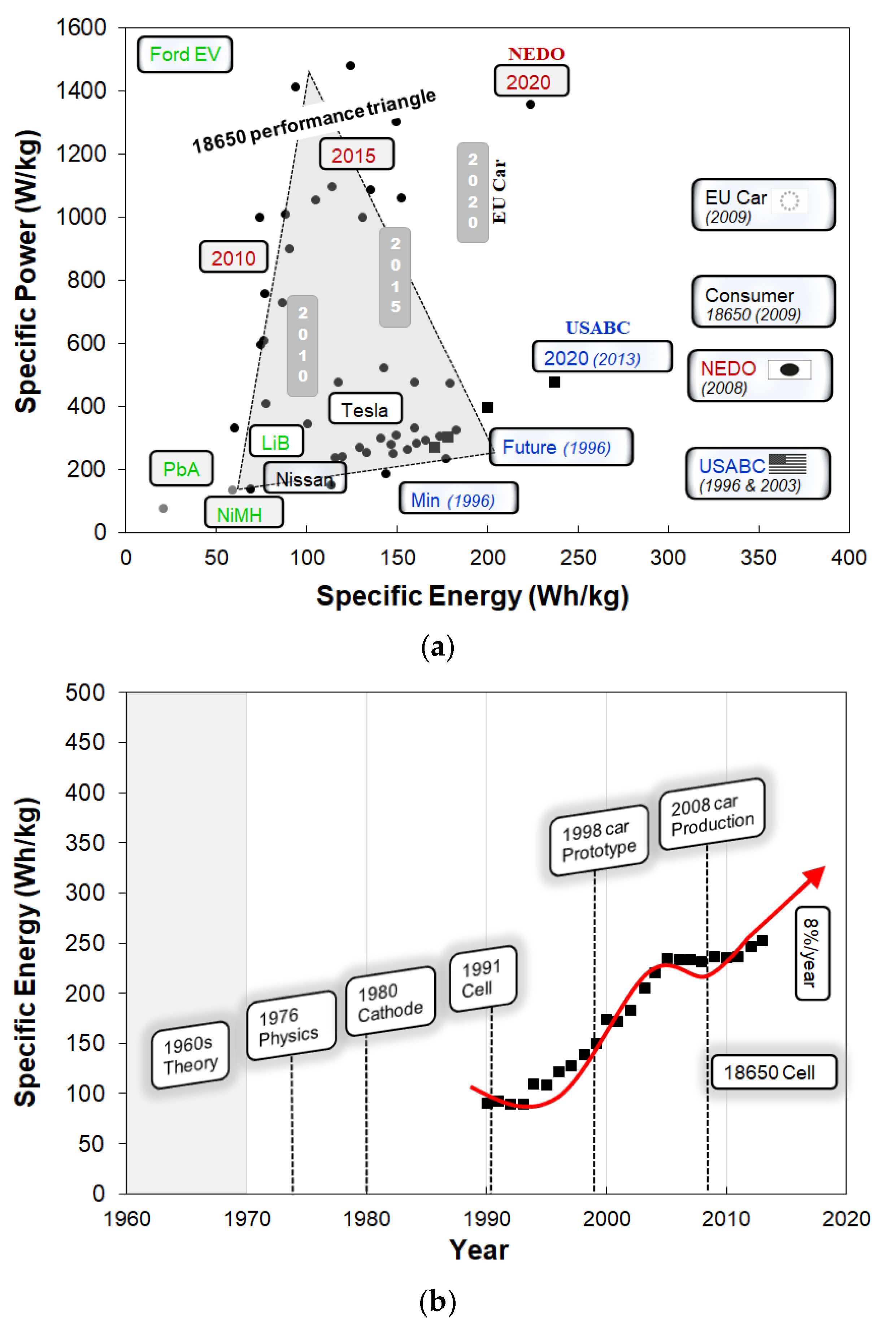
:1. Introduction

2. Modeling of Battery Thermal Management System
2.1. Lumped-Capacitance Thermal Model and Flow Network Model
2.2. Spatial-Resolution Lumped-Capacitance Thermal Model
2.3. Equivalent-Circuit Model (ECM)
2.4. Impedance-Based Temperature Detection (ITD) Model
2.5. Data-Driven Model and Implementation of IoT-Cloud Infrastructure
3. Thermal Management Practices
3.1. Air-Driven Battery Thermal Management


3.2. Liquid-Based Thermal Management

| Authors | Strategies | Recommendations | Methods |
|---|---|---|---|
| Yu et al. (2005) [122] | Thermal management of PEM fuel cell stack | An earlier model of water and thermal management system was based upon mathematical analysis to attain the optimum result. | Mathematical |
| Giuliano et al. (2011) [23] | Aluminum cooling plates | At 300 A discharges, the proposed system was able to control the temperature below 50 °C. | Experiment |
| Jarrett and Kim (2011, 2014) [123,124] | Serpentine- channel shape cooling plate | A serpentine channel shape cooling panel could optimize pressure drop and maximum cell temperature; although, the temperature differential increased. The temperature uniformity was found to be most sensitive to the design operating conditions, especially the heat flux and flow rate. | Numerical simulation |
| Hung et al. (2013) [125] | Nanofluids (Al2O3/water) | For a nanofluidic-based system, the most efficient performance was obtained when nanofluid concentrations were ~0.5%, while the flow rate was significantly lower (0.8 L/min). | Experiment |
| Bandhaeur et al. (2013) [126] | Passive microchannel phase change system (Liquid R134a) | A new two-phase refrigerant in the microchannel was tested for a passive internal thermal management system. A correlation for the friction factor for such a two-phase system was proposed and tested. | Experiment |
| Lan et al. (2014) [127] | Mini-channel cooling | With a minimum expense of pumping power, the proposed system can reduce both the cell temperature and the pack temperature differential. At a discharge rate of 1 C, using a flow rate of 0.20 L/min, the maximum temperature rise was less than 27.81 °C, whereas the temperature differential was 0.80 °C after 1 h of discharging, with only 8.69 × 10⁻⁶ W pumping power required. | Numerical simulation |
| Nieto et al. (2014) [128] | Cold plate | Maximum cell temperature and pack temperature differential were lower than 35 °C and 5 °C, respectively. | Experiment, numerical simulation |
| Panchal et al. (2016) [113] | Mini-channel water cooling | A mini-channel water cooling system was tested for large prismatic cells for the discharge of 1–2 C and operating temperatures of 5–25 °C. | Experiment, numerical simulation |
| Huo et al. (2014) [118] | Nanofluids (Al2O3/water) | In a five cells pack, the Al2O3/water nanofluids decreased the maximum cell temperature and also maintained the temperature uniformity. For a 0.4 volume fraction of nanofluids, a maximum 7% decrease in maximum cell temperature was obtained. | Numerical simulation |
| Qian et al. (2014) [129] | Geometries of inlet and outlet flow ducts | The mini-channel cold plate could attain the optimum operating temperature when the discharge rate was as high as 5 C. The cell temperature (maximum) and the pack temperature differential decreased by 13.3% and 43.3%, respectively. | Analytical, numerical simulation |
| Zhang et al. (2014) [130] | Water-based PAAS (sodium polyacrylate) hydrogel | The simulation and experimental results at a significantly high discharge (10 A) demonstrate the excellent performance of the hydrogel TMS in decreasing the temperature gain and minimizing the temperature gradient inside the pack. A battery pack equipped with the hydrogel TMS exhibits a reduced capacity fading. | Experiment, numerical simulation |
| Jin et al. (2014) [131] | Oblique minichannel liquid cold plate | An oblique alignment of a mini-channel liquid cold plate was applied, where the performance was significantly higher than with the normal liquid cold plate. The proposed structure could keep the maximum surface temperature below the critical limit (50 °C) even for a high thermal load (~1240 W) and a low flow rate (~0.9 L/min). | Experiment, numerical simulation |
| Tong et al. (2015) [132] | Water and coolant plate | The thermal performance of the battery pack could be improved by extending the coolant plate thickness and flow rate. The proposed system could also increase the weight or volume; hence, an optimum design condition is necessary. | Numerical simulation |
| Huo et al. (2015) [133] | Mini-channel cold plate | The maximum cell temperature decreased if the number of cooling channels increased. The coolant performance could be improved with a water flow lateral to the electrodes. The thermal performance can be enhanced by increasing the flow rate; however, the efficiency could decrease above the optimum operating conditions. | Numerical simulation |
| Saw et al. (2015) [134] | Liquid cooling | Thermal management systems were analyzed for liquid and air cooling. It was suggested that among various methods available, the direct contact liquid cooling system was more effective in extracting the heat generated in the cell and creating an optimum operating environment for the battery. | Numerical simulation |
| Smith et al. (2015) [135] | Three sample cooling plate concepts | It was shown that the ideal cooling plate design depends on the anticipated cell heat loss and operating climate, as well as the degree of structural integration within the vehicle. | Experiment |
| Chen et al. (2016) [136] | Direct liquid, indirect liquid, fin, and air cooling | A 3-dimensional electrochemical–thermal model was applied to evaluate four BTMS (air, direct liquid cooling, indirect liquid cooling, and fin-type) and compared. Maintaining the same average temperature for the air-based method needed two to three times higher energy. However, water/glycol was most efficient in reducing the cell temperature compared to oil, air, or fins. | Numerical simulation |
| Basu et al. (2016) [137] | Aluminum sheets wrapping/Liquid coolant | The proposed system could reduce the maximum cell temperature below 7 K even at high discharge. In addition, the system was found to be efficient in cooling the pack at low flow rates. | Experiment, numerical simulation |
| Mondal et al. (2017) [138] | Nanofluids (ethylene glycol, Al2O3, CuO) | Pure H2O-based coolants offered better thermal performance in the form of lower overall temperatures and less temperature gradient. The enrichment with nanoparticles did not have a significant impact on the pack temperature, despite the increase in thermal conductivity. | Numerical simulation |
| An et al. (2017) [139] | Mini-channel (flow boiling) | The BTMS devised on hydrofluoroether flow boiling in micro-channels could keep temperatures of battery cells around 40 °C and could improve the temperature uniformity in the cell. | Experiment |
| Gao et al. (2022) [140] | Gradient channel based | Optimally designed gradient channel design can enhance the cooling performance of the BTMS. The proposed design can significantly improve the thermal uniformity in the pack for a lower inlet flow rate. | Experiment, numerical simulation |
3.3. PCM-Based Thermal Management
3.4. In Situ Thermal Management
3.5. Heat Pipes and Thermoelectric Modules
4. Conclusions
Funding
Conflicts of Interest
References
- Pistoia, G. Lithium-Ion Batteries: Advances and Applications, 1st ed.; Elsevier: Amsterdam, The Netherlands, 2014. [Google Scholar]
- Linden, D.; Reddy, T.B. Handbook of Batteries, 3rd ed.; McGraw-Hill: New York, NY, USA, 2002. [Google Scholar]
- Pistoia, G.; Liaw, B. Behaviour of Lithium-Ion Batteries in Electric Vehicles: Battery Health, Performance, Safety, and Cost; Green Energy and Technology: Cham, Switzerland, 2018. [Google Scholar]
- Scrosati, B.; Garche, J.; Tillmetz, W. Advances in Battery Technologies for Electric Vehicles, 1st ed.; Woodhead Publishing: Cambridge, UK, 2015. [Google Scholar]
- Dinçer, I.; Hamut, H.S.; Javani, N. Thermal Management of Electric Vehicle Battery Systems; Wiley: Hoboken, NJ, USA, 2017. [Google Scholar]
- Goodenough, J.B. Theory of the Role of Covalence in the Perovskite-Type Manganites[La, M(II)]MnO3. Phys. Rev. 1955, 100, 564–573. [Google Scholar] [CrossRef] [Green Version]
- Mizushima, K.; Jones, P.C.; Wiseman, P.J.; Goodenough, J.B. LixCoO2 (0 < x ≤ 1): A new cathode material for batteries of high energy density. Mater. Res. Bull. 1980, 15, 783–789. [Google Scholar]
- Goodenough, J.B.; Schuman, B. Manganese Oxides as Battery Cathodes. In Proceedings Symposium on Manganese Dioxide Electrode: Theory and Practice for Electrochemical Applications; Re Electrochem. Soc.: Hoboken, NJ, USA, 1985; Volume 85–84, pp. 77–96. [Google Scholar]
- Ohzuku, T.; Brodd, R.J. An overview of positive-electrode materials for advanced lithium-ion batteries. J. Power Sources 2007, 174, 449–456. [Google Scholar] [CrossRef]
- Lee, S.; Kwon, G.; Ku, K.; Yoon, K.; Jung, S.-K.; Lim, H.-D.; Kang, K. Recent Progress in Organic Electrodes for Li and Na Rechargeable Batteries. Adv. Mater. 2018, 30, e1704682. [Google Scholar] [CrossRef] [PubMed]
- Peng, L.; Shen, X.; Dai, J.; Wang, X.; Zeng, J.; Huang, B.; Li, H.; Zhang, P.; Zhao, J. Three-Dimensional Coating Layer Modified Polyolefin Ceramic-Coated Separators to Enhance the Safety Performance of Lithium-Ion Batteries. J. Electrochem. Soc. 2019, 166, A2111–A2120. [Google Scholar] [CrossRef]
- Chen, X.; Chen, S.; Lin, Y.; Wu, K.; Lu, S. Multi-functional ceramic-coated separator for lithium-ion batteries safety tolerance improvement. Ceram. Int. 2020, 46, 24689–24697. [Google Scholar] [CrossRef]
- Teki, R.; Datta, M.K.; Krishnan, R.; Parker, T.; Lu, T.-M.; Kumta, P.N.; Koratkar, N. Nanostructured Silicon Anodes for Lithium Ion Rechargeable Batteries. Small 2009, 5, 2236–2242. [Google Scholar] [CrossRef]
- Freitag, S.; Berger, C.; Gelb, J.; Zeiss, C.; Weisenberger, C.; Berthaler, T. Scanning Electron Microscopy of Lithium-Lon Battery Components. Available online: https://blogs.zeiss.com/microscopy/en/2016 (accessed on 19 May 2022).
- Wang, Q.; Ping, P.; Zhao, X.; Chu, G.; Sun, J.; Chen, C. Thermal runaway caused fire and explosion of lithium ion battery. J. Power Sources 2012, 208, 210–224. [Google Scholar] [CrossRef]
- Liu, H.; Wei, Z.; He, W.; Zhao, J. Thermal issues about Li-ion batteries and recent progress in battery thermal management systems: A review. Energy Convers. Manag. 2017, 150, 304–330. [Google Scholar] [CrossRef]
- Feng, X.; Ren, D.; He, X.; Ouyang, M. Mitigating Thermal Runaway of Lithium-Ion Batteries. Joule 2020, 4, 743–770. [Google Scholar] [CrossRef]
- Wu, Y.-S.; Pham, Q.-T.; Yangabg, C.C.; Chernd, C.S.; Babulal, L.M.; Seenivasana, M.; Brunklausf, G.; Plackee, T.; Hwangd, B.J.; Winteref, M. Study of electrochemical performance and thermal property of LiNi0.5Co0.2Mn0.3O2 cathode materials coated with a novel oligomer additive for high-safety lithium-ion batteries. Chem. Eng. J. 2020, 405, 126727. [Google Scholar] [CrossRef]
- Friesen, A.; Hildebrand, S.; Horsthemke, F.; Börner, M.; Klöpsch, R.; Niehoff, P.; Schappacher, F.M.; Winter, M. Al2O3 coating on anode surface in lithium ion batteries: Impact on low temperature cycling and safety behavior. J. Power Sources 2017, 363, 70–77. [Google Scholar] [CrossRef]
- Mahmoud, A.; Saadoune, I.; Lippens, P.-E.; Chamas, M.; Hakkou, R.; Amarilla, J.M. The design and study of new Li-ion full cells of LiCo2/3Ni1/6Mn1/6O2 positive electrode paired with MnSn2 and Li4Ti5O12 negative electrodes. Solid State Ionics 2017, 300, 175–181. [Google Scholar] [CrossRef]
- Zinth, V.; von Lüders, C.; Hofmann, M.; Hattendorff, J.; Buchberger, I.; Erhard, S.; Rebelo-Kornmeier, J.; Jossen, A.; Gilles, R. Lithium plating in lithium-ion batteries at sub-ambient temperatures investigated by in situ neutron diffraction. J. Power Sources 2014, 271, 152–159. [Google Scholar] [CrossRef]
- Xu, J.; Chao, J.; Li, T.; Yan, T.; Wu, S.; Wu, M.; Zhao, B.; Wang, R. Near-Zero-Energy Smart Battery Thermal Management Enabled by Sorption Energy Harvesting from Air. ACS Central Sci. 2020, 6, 1542–1554. [Google Scholar] [CrossRef]
- Giuliano, M.R.; Advani, S.G.; Prasad, A.K. Thermal analysis and management of lithium–titanate batteries. J. Power Sources 2011, 196, 6517–6524. [Google Scholar] [CrossRef]
- Ji, Y.; Wang, C.Y. Heating strategies for Li-ion batteries operated from subzero temperatures. Electrochim. Acta 2013, 107, 664–674. [Google Scholar] [CrossRef]
- Jaguemont, J.; Boulon, L.; Dube, Y.; Martel, F. Thermal Management of a Hybrid Electric Vehicle in Cold Weather. IEEE Trans. Energy Convers. 2016, 31, 1110–1120. [Google Scholar] [CrossRef]
- Waldmann, T.; Hogg, B.-I.; Wohlfahrt-Mehrens, M. Li plating as unwanted side reaction in commercial Li-ion cells—A review. J. Power Sources 2018, 384, 107–124. [Google Scholar] [CrossRef]
- Feng, X.; Ouyang, M.; Liu, X.; Lu, L.; Xia, Y.; He, X. Thermal runaway mechanism of lithium ion battery for electric vehicles: A review. Energy Storage Mater. 2017, 10, 246–267. [Google Scholar] [CrossRef]
- Hosseinzadeh, E.; Genieser, R.; Worwood, D.; Barai, A.; Marco, J.; Jennings, P. A systematic approach for electrochemical-thermal modelling of a large format lithium-ion battery for electric vehicle application. J. Power Sources 2018, 382, 77–94. [Google Scholar] [CrossRef] [Green Version]
- Murashko, K. Thermal Modelling of Commercial Lithium-Ion Batteries; Lappeenranta University of Technology: Lappeenranta, Finland, 2016. [Google Scholar]
- Waldmann, T.; Scurtu, R.-G.; Richter, K.; Wohlfahrt-Mehrens, M. 18650 vs. 21700 Li-ion cells—A direct comparison of electrochemical, thermal, and geometrical properties. J. Power Sources 2020, 472, 228614. [Google Scholar] [CrossRef]
- Murray, V.; Hall, D.S.; Dahn, J.R. A Guide to Full Coin Cell Making for Academic Researchers. J. Electrochem. Soc. 2019, 166, A329–A333. [Google Scholar] [CrossRef]
- Quinn, J.B.; Waldmann, T.; Richter, K.; Kasper, M.; Wohlfahrt-Mehrens, M. Energy Density of Cylindrical Li-Ion Cells: A Comparison of Commercial 18650 to the 21700 Cells. J. Electrochem. Soc. 2018, 165, A3284–A3291. [Google Scholar] [CrossRef]
- Battery-Experts-Forum. Available online: https://www.battery-experts-forum.com/index.php/en/ (accessed on 19 May 2022).
- Batteries in a Portable World. Available online: https://batteryuniversity.com/ (accessed on 19 May 2022).
- Tarascon, J.-M.; Armand, M. Issues and challenges facing rechargeable lithium batteries. Nature 2001, 414, 359–367. [Google Scholar] [CrossRef] [PubMed]
- Mahamud, R.; Park, C. Reciprocating air flow for Li-ion battery thermal management to improve temperature uniformity. J. Power Sources 2011, 196, 5685–5696. [Google Scholar] [CrossRef]
- Mahamud, R. Advanced Battery Thermal Management for Electrical-Drive Vehicles Using Reciprocating Cooling Flow and Spatial-Resolution, Lumped-Capacitance Thermal Model; University of Nevada Reno: Reno, NV, USA, 2017. [Google Scholar]
- Mahamud, R.; Park, C. Spatial-resolution, lumped-capacitance thermal model for cylindrical Li-ion batteries under high Biot number conditions. Appl. Math. Model. 2013, 37, 2787–2801. [Google Scholar] [CrossRef]
- Mahamud, R.; Park, C. Spatial-Resolution, Lumped-Capacitance Thermal Model for Battery Power Cycle Analysis. In Proceedings of the SAE 2011 World Congress & Exhibition, Detroit, MI, USA, 12 April 2011. [Google Scholar]
- Liaw, B.Y.; Nagasubramanian, G.; Jungst, R.G.; Doughty, D.H. Modeling of lithium ion cells?A simple equivalent-circuit model approach. Solid State Ionics 2004, 175, 835–839. [Google Scholar] [CrossRef]
- Moss, P.L.; Au, G.; Plichta, E.J.; Zheng, J.P. An Electrical Circuit for Modeling the Dynamic Response of Li-Ion Polymer Batteries. J. Electrochem. Soc. 2008, 155, A986–A994. [Google Scholar] [CrossRef]
- Gan, Y.; Wang, J.; Liang, J.; Huang, Z.; Hu, M. Development of thermal equivalent circuit model of heat pipe-based thermal management system for a battery module with cylindrical cells. Appl. Therm. Eng. 2020, 164, 114523. [Google Scholar] [CrossRef]
- Richardson, R. Impedance-Based Battery Temperature Monitoring; University of Oxford: Oxford, UK, 2016. [Google Scholar]
- Richardson, R.R.; Zhao, S.; Howey, D.A. On-board monitoring of 2-D spatially-resolved temperatures in cylindrical lithium-ion batteries: Part I. Low-order thermal modelling. J. Power Sources 2016, 326, 377–388. [Google Scholar] [CrossRef] [Green Version]
- Tran, M.; Panchal, S.; Chauhan, V.; Brahmbhatt, N.; Mevawalla, A.; Fraser, R.; Fowler, M. Python-based scikit-learn machine learning models for thermal and electrical performance prediction of high-capacity lithium-ion battery. Int. J. Energy Res. 2021, 46, 786–794. [Google Scholar] [CrossRef]
- Afzal, A.; Bhutto, J.K.; Alrobaian, A.; Kaladgi, A.R.; Khan, S.A. Modelling and Computational Experiment to Obtain Optimized Neural Network for Battery Thermal Management Data. Energies 2021, 14, 7370. [Google Scholar] [CrossRef]
- Park, C.-W.; Jaura, A.K. Transient Heat Transfer of 42V Ni-MH Batteries for an HEV Application. SAE Trans. 2002, 111, 803–808. [Google Scholar]
- Liu, Z.; Wang, Y.; Zhang, J.; Liu, Z. Shortcut computation for the thermal management of a large air-cooled battery pack. Appl. Therm. Eng. 2014, 66, 445–452. [Google Scholar] [CrossRef]
- Liu, R.; Chen, J.; Xun, J.; Jiao, K.; Du, Q. Numerical investigation of thermal behaviors in lithium-ion battery stack discharge. Appl. Energy 2014, 132, 288–297. [Google Scholar] [CrossRef]
- Nieto, N.; Díaz, L.; Gastelurrutia, J.; Alava, I.; Blanco, F.; Ramos, J.C.; Rivas, A. Thermal Modeling of Large Format Lithium-Ion Cells. J. Electrochem. Soc. 2012, 160, A212–A217. [Google Scholar] [CrossRef]
- Ratnakumar, B.; Smart, M.; Whitcanack, L.; Ewell, R. The impedance characteristics of Mars Exploration Rover Li-ion batteries. J. Power Sources 2006, 159, 1428–1439. [Google Scholar] [CrossRef]
- Sato, N. Thermal behavior analysis of lithium-ion batteries for electric and hybrid vehicles. J. Power Sources 2001, 99, 70–77. [Google Scholar] [CrossRef]
- Li, Y.; Zhou, Z.; Wu, W.-T. Three-Dimensional Thermal Modeling of Internal Shorting Process in a 20Ah Lithium-Ion Polymer Battery. Energies 2020, 13, 1013. [Google Scholar] [CrossRef] [Green Version]
- Rizk, R.; Louahlia, H.; Gualous, H.; Schaetzel, P. Experimental analysis and transient thermal modelling of a high capacity prismatic lithium-ion battery. Int. Commun. Heat Mass Transf. 2018, 94, 115–125. [Google Scholar] [CrossRef]
- Al Hallaj, S.; Venkatachalapathy, R.; Prakash, J.; Selman, J.R. Entropy Changes Due to Structural Transformation in the Graphite Anode and Phase Change of the LiCoO[sub 2] Cathode. J. Electrochem. Soc. 2000, 147, 2432. [Google Scholar] [CrossRef]
- Motloch, C.G.; Christophersen, J.P.; Belt, J.R.; Wright, R.B.; Hunt, G.L.; Sutula, R.A.; Duong, T.; Tartamella, T.J.; Haskins, H.J.; Miller, T.J. High-Power Battery Testing Procedures and Analytical Methodologies for HEV’s. SAE Trans. 2002, 111, 797–802. [Google Scholar]
- Srinivasan, V.; Wang, C.Y. Analysis of Electrochemical and Thermal Behavior of Li-Ion Cells. J. Electrochem. Soc. 2002, 150, A98–A106. [Google Scholar] [CrossRef] [Green Version]
- Thomas, K.E.; Bogatu, C.; Newman, J. Measurement of the Entropy of Reaction as a Function of State of Charge in Doped and Undoped Lithium Manganese Oxide. J. Electrochem. Soc. 2001, 148, A570–A575. [Google Scholar] [CrossRef]
- Smith, K.; Wang, C.-Y. Solid-state diffusion limitations on pulse operation of a lithium ion cell for hybrid electric vehicles. J. Power Sources 2006, 161, 628–639. [Google Scholar] [CrossRef]
- Zukauskas, A.; Ulinskas, R. Heat Transfer in Tube Banks in Crossflow; Hemisphere Publishing: New York, NY, USA, 1988. [Google Scholar]
- Whitaker, S. Forced convection heat transfer correlations for flow in pipes, past flat plates, single cylinders, single spheres, and for flow in packed beds and tube bundles. AIChE J. 1972, 18, 361–371. [Google Scholar] [CrossRef]
- Frank, P.; Incropera, D.P.D.; Theodore, L.; Adrienne, S.B. Lavine Introduction to Heat Transfer; Wiley & Sons, Inc.: New York, NY, USA, 2007. [Google Scholar]
- Gaddis, E.S.; Gnielinski, V. Pressure Drop in Cross Flow across Tube Bundles. Int. Chem. Eng. 1985, 25, 1–15. [Google Scholar]
- Cotta, R.M. Improved lumped-differential formulation of diffusion problems. In Modeling of Engineering Heat Transfer Phenomena; Sunden, B.M.F., Ed.; Computational Mechanics Publications: Southampton, UK, 1999; Volume 2. [Google Scholar]
- Verbrugge, M.W.; Conell, R.S. Electrochemical and Thermal Characterization of Battery Modules Commensurate with Electric Vehicle Integration. J. Electrochem. Soc. 2002, 149, A45–A53. [Google Scholar] [CrossRef]
- Lin, X.; Perez, H.E.; Mohan, S.; Siegel, J.; Stefanopoulou, A.G.; Ding, Y.; Castanier, M.P. A lumped-parameter electro-thermal model for cylindrical batteries. J. Power Sources 2014, 257, 1–11. [Google Scholar] [CrossRef]
- Pan, Y.-W.; Hua, Y.; Zhou, S.; He, R.; Zhang, Y.; Yang, S.; Liu, X.; Lian, Y.; Yan, X.; Wu, B. A computational multi-node electro-thermal model for large prismatic lithium-ion batteries. J. Power Sources 2020, 459, 228070. [Google Scholar] [CrossRef]
- Liang, J.; Gan, Y.; Yao, M.; Li, Y. Numerical analysis of capacity fading for a LiFePO4 battery under different current rates and ambient temperatures. Int. J. Heat Mass Transf. 2020, 165, 120615. [Google Scholar] [CrossRef]
- Richardson, R.R.; Ireland, P.T.; Howey, D. Battery internal temperature estimation by combined impedance and surface temperature measurement. J. Power Sources 2014, 265, 254–261. [Google Scholar] [CrossRef]
- Kolodziejczyk, F.; Mortazavi, B.; Rabczuk, T.; Zhuang, X. Machine learning assisted multiscale modeling of composite phase change materials for Li-ion batteries’ thermal management. Int. J. Heat Mass Transf. 2021, 172, 121199. [Google Scholar] [CrossRef]
- Wen, J.; Zou, Q.; Wei, Y. Physics-driven machine learning model on temperature and time-dependent deformation in lithium metal and its finite element implementation. J. Mech. Phys. Solids 2021, 153, 104481. [Google Scholar] [CrossRef]
- Deng, Z.; Hu, X.; Lin, X.; Che, Y.; Xu, L.; Guo, W. Data-driven state of charge estimation for lithium-ion battery packs based on Gaussian process regression. Energy 2020, 205, 118000. [Google Scholar] [CrossRef]
- Li, W.; Garg, A.; Xiao, M.; Gao, L. Optimization for Liquid Cooling Cylindrical Battery Thermal Management System Based on Gaussian Process Model. J. Therm. Sci. Eng. Appl. 2020, 13, 1–19. [Google Scholar] [CrossRef]
- Feng, F.; Teng, S.; Liu, K.; Xie, J.; Xie, Y.; Liu, B.; Li, K. Co-estimation of lithium-ion battery state of charge and state of temperature based on a hybrid electrochemical-thermal-neural-network model. J. Power Sources 2020, 455, 227935. [Google Scholar] [CrossRef]
- Kleiner, J.; Stuckenberger, M.; Komsiyska, L.; Endisch, C. Advanced Monitoring and Prediction of the Thermal State of Intelligent Battery Cells in Electric Vehicles by Physics-Based and Data-Driven Modeling. Batteries 2021, 7, 31. [Google Scholar] [CrossRef]
- Hu, X.; Lin, S.; Stanton, S.; Lian, W. A Foster Network Thermal Model for HEV/EV Battery Modeling. IEEE Trans. Ind. Appl. 2011, 47, 1692–1699. [Google Scholar] [CrossRef]
- Solai, E.; Guadagnini, M.; Beaugendre, H.; Daccord, R.; Congedo, P. Validation of a data-driven fast numerical model to simulate the immersion cooling of a lithium-ion battery pack. Energy 2022, 249, 123633. [Google Scholar] [CrossRef]
- Kong, L.; Khan, M.K.; Wu, F.; Chen, G.; Zeng, P. Millimeter-Wave Wireless Communications for IoT-Cloud Supported Autonomous Vehicles: Overview, Design, and Challenges. IEEE Commun. Mag. 2017, 55, 62–68. [Google Scholar] [CrossRef]
- Bellotti, F.; Berta, R.; Kobeissi, A.; Osman, N.; Arnold, E.; Dianati, M.; Nagy, B.; Gloria, A.D. Designing an IoT Framework for Automated Driving Impact Analysis. In Proceedings of the 2019 IEEE Intelligent Vehicles Symposium (IV), Paris, France, 9–12 June 2019; pp. 1111–1117. [Google Scholar]
- Celesti, A.; Galletta, A.; Carnevale, L.; Fazio, M.; Lay-Ekuakille, A.; Villari, M. An IoT Cloud System for Traffic Monitoring and Vehicular Accidents Prevention Based on Mobile Sensor Data Processing. IEEE Sens. J. 2017, 18, 4795–4802. [Google Scholar] [CrossRef]
- Kobeissi, A.H.; Bellotti, F.; Berta, R.; Gloria, A.D. IoT Grid Alignment Assistant System for Dynamic Wireless Charging of Electric Vehicles. In Proceedings of the 2018 Fifth International Conference on Internet of Things: Systems, Management and Security, Valencia, Spain, 15–18 October 2018; pp. 274–279. [Google Scholar]
- Tran, M.-K.; Panchal, S.; Khang, T.D.; Panchal, K.; Fraser, R.; Fowler, M. Concept Review of a Cloud-Based Smart Battery Management System for Lithium-Ion Batteries: Feasibility, Logistics, and Functionality. Batteries 2022, 8, 19. [Google Scholar] [CrossRef]
- Kim, Y.; Oh, H.; Kang, S. Proof of Concept of Home IoT Connected Vehicles. Sensors 2017, 17, 1289. [Google Scholar] [CrossRef] [PubMed] [Green Version]
- Shabani, B.; Biju, M. Theoretical Modelling Methods for Thermal Management of Batteries. Energies 2015, 8, 10153–10177. [Google Scholar] [CrossRef]
- Pesaran, A.A.; Burch, S.; Keyser, M. An Approach for Designing Thermal Management Systems for Electric and Hybrid Vehicle Battery Packs. In Proceedings of the Fourth Vehicle Thermal Management Systems Conference and Exhibition, London, UK, 24–27 May 1999. [Google Scholar]
- Wang, T.; Tseng, K.; Zhao, J.; Wei, Z. Thermal investigation of lithium-ion battery module with different cell arrangement structures and forced air-cooling strategies. Appl. Energy 2014, 134, 229–238. [Google Scholar] [CrossRef]
- Yang, N.; Zhang, X.; Li, G.; Hua, D. Assessment of the forced air-cooling performance for cylindrical lithium-ion battery packs: A comparative analysis between aligned and staggered cell arrangements. Appl. Therm. Eng. 2015, 80, 55–65. [Google Scholar] [CrossRef]
- Yang, T.; Yang, N.; Zhang, X.; Li, G. Investigation of the thermal performance of axial-flow air cooling for the lithium-ion battery pack. Int. J. Therm. Sci. 2016, 108, 132–144. [Google Scholar] [CrossRef]
- Afzal, A.; Samee, A.D.M.; Razak, R.K.A.; Ramis, M.K. Effect of spacing on thermal performance characteristics of Li-ion battery cells. J. Therm. Anal. 2018, 135, 1797–1811. [Google Scholar] [CrossRef]
- Afzal, A.; Mujeebu, M.A. Thermo-Mechanical and Structural Performances of Automobile Disc Brakes: A Review of Numerical and Experimental Studies. Arch. Comput. Methods Eng. 2018, 26, 1489–1513. [Google Scholar] [CrossRef]
- Park, S.; Jung, D. Battery cell arrangement and heat transfer fluid effects on the parasitic power consumption and the cell temperature distribution in a hybrid electric vehicle. J. Power Sources 2013, 227, 191–198. [Google Scholar] [CrossRef]
- Sun, H.; Dixon, R. Development of cooling strategy for an air cooled lithium-ion battery pack. J. Power Sources 2014, 272, 404–414. [Google Scholar] [CrossRef]
- Chen, K.; Wang, S.; Song, M.; Chen, L. Structure optimization of parallel air-cooled battery thermal management system. Int. J. Heat Mass Transf. 2017, 111, 943–952. [Google Scholar] [CrossRef]
- Jiaqiang, E.; Yue, M.; Chen, J.; Zhu, H.; Deng, Y.; Zhu, Y.; Zhang, F.; Wen, M.; Zhang, B.; Kang, S. Effects of the different air cooling strategies on cooling performance of a lithium-ion battery module with baffle. Appl. Therm. Eng. 2018, 144, 231–241. [Google Scholar] [CrossRef]
- Shahid, S.; Agelin-Chaab, M. Development and analysis of a technique to improve air-cooling and temperature uniformity in a battery pack for cylindrical batteries. Therm. Sci. Eng. Prog. 2018, 5, 351–363. [Google Scholar] [CrossRef]
- Hong, S.; Zhang, X.; Chen, K.; Wang, S. Design of flow configuration for parallel air-cooled battery thermal management system with secondary vent. Int. J. Heat Mass Transf. 2018, 116, 1204–1212. [Google Scholar] [CrossRef]
- Zhao, G.; Wang, X.; Negnevitsky, M.; Zhang, H. A review of air-cooling battery thermal management systems for electric and hybrid electric vehicles. J. Power Sources 2021, 501, 230001. [Google Scholar] [CrossRef]
- Behi, H.; Karimi, D.; Behi, M.; Ghanbarpour, M.; Jaguemont, J.; Sokkeh, M.A.; Gandoman, F.H.; Berecibar, M.; Van Mierlo, J. A new concept of thermal management system in Li-ion battery using air cooling and heat pipe for electric vehicles. Appl. Therm. Eng. 2020, 174, 115280. [Google Scholar] [CrossRef]
- Yi, J.; Koo, B.; Shin, C.B.; Han, T.; Park, S. Modeling the effect of aging on the electrical and thermal behaviors of a lithium-ion battery during constant current charge and discharge cycling. Comput. Chem. Eng. 2017, 99, 31–39. [Google Scholar] [CrossRef]
- Cho, G.Y.; Choi, J.W.; Park, J.H.; Cha, S.W. Transient modeling and validation of lithium ion battery pack with air cooled thermal management system for electric vehicles. Int. J. Automot. Technol. 2014, 15, 795–803. [Google Scholar] [CrossRef]
- Fan, Y.; Bao, Y.; Ling, C.; Chu, Y.; Tan, X.; Yang, S. Experimental study on the thermal management performance of air cooling for high energy density cylindrical lithium-ion batteries. Appl. Therm. Eng. 2019, 155, 96–109. [Google Scholar] [CrossRef]
- Liu, Y.; Zhang, J. Design a J-type air-based battery thermal management system through surrogate-based optimization. Appl. Energy 2019, 252, 113426. [Google Scholar] [CrossRef]
- He, H.; Jia, H.; Huo, W.; Sun, F. Field Synergy Analysis and Optimization of the Thermal Behavior of Lithium Ion Battery Packs. Energies 2017, 10, 81. [Google Scholar] [CrossRef] [Green Version]
- Xu, X.; He, R. Research on the heat dissipation performance of battery pack based on forced air cooling. J. Power Sources 2013, 240, 33–41. [Google Scholar] [CrossRef]
- Wang, T.; Tseng, K.; Zhao, J. Development of efficient air-cooling strategies for lithium-ion battery module based on empirical heat source model. Appl. Therm. Eng. 2015, 90, 521–529. [Google Scholar] [CrossRef]
- Saw, B.; Ye, Y.; Tay, A.A.; Chong, W.T.; Kuan, S.H.; Yew, M.C. Computational fluid dynamic and thermal analysis of Lithium-ion battery pack with air cooling. Appl. Energy 2016, 177, 783–792. [Google Scholar] [CrossRef]
- Erb, D.; Kumar, S.; Carlson, E.; Ehrenberg, I.; Sarma, S. Analytical methods for determining the effects of lithium-ion cell size in aligned air-cooled battery packs. J. Energy Storage 2017, 10, 39–47. [Google Scholar] [CrossRef]
- Shahid, S.; Agelin-Chaab, M. Experimental and numerical studies on air cooling and temperature uniformity in a battery pack. Int. J. Energy Res. 2018, 42, 2246–2262. [Google Scholar] [CrossRef]
- Na, X.; Kang, H.; Wang, T.; Wang, Y. Reverse layered air flow for Li-ion battery thermal management. Appl. Therm. Eng. 2018, 143, 257–262. [Google Scholar] [CrossRef]
- Chen, K.; Song, M.; Wei, W.; Wang, S. Design of the structure of battery pack in parallel air-cooled battery thermal management system for cooling efficiency improvement. Int. J. Heat Mass Transf. 2019, 132, 309–321. [Google Scholar] [CrossRef]
- Peng, X.; Ma, C.; Garg, A.; Bao, N.; Liao, X. Thermal performance investigation of an air-cooled lithium-ion battery pack considering the inconsistency of battery cells. Appl. Therm. Eng. 2019, 153, 596–603. [Google Scholar] [CrossRef]
- He, F.; Ma, L. Thermal management of batteries employing active temperature control and reciprocating cooling flow. Int. J. Heat Mass Transf. 2015, 83, 164–172. [Google Scholar] [CrossRef]
- Panchal, S.; Khasow, R.; Dincer, I.; Agelin-Chaab, M.; Fraser, R.; Fowler, M. Thermal design and simulation of mini-channel cold plate for water cooled large sized prismatic lithium-ion battery. Appl. Therm. Eng. 2017, 122, 80–90. [Google Scholar] [CrossRef]
- Du, X.; Qian, Z.; Chen, Z.; Rao, Z. Experimental investigation on mini-channel cooling-based thermal management for Li-ion battery module under different cooling schemes. Int. J. Energy Res. 2018, 42, 2781–2788. [Google Scholar] [CrossRef]
- Zhao, J.; Rao, Z.; Li, Y. Thermal performance of mini-channel liquid cooled cylinder based battery thermal management for cylindrical lithium-ion power battery. Energy Convers. Manag. 2015, 103, 157–165. [Google Scholar] [CrossRef]
- Thakur, A.K.; Prabakaran, R.; Elkadeem, M.; Sharshir, S.W.; Arıcı, M.; Wang, C.; Zhao, W.; Hwang, J.-Y.; Saidur, R. A state of art review and future viewpoint on advance cooling techniques for Lithium–ion battery system of electric vehicles. J. Energy Storage 2020, 32, 101771. [Google Scholar] [CrossRef]
- Al-Zareer, M.; Dincer, I.; Rosen, M.A. A novel approach for performance improvement of liquid to vapor based battery cooling systems. Energy Convers. Manag. 2019, 187, 191–204. [Google Scholar] [CrossRef]
- Huo, Y.; Rao, Z. The numerical investigation of nanofluid based cylinder battery thermal management using lattice Boltzmann method. Int. J. Heat Mass Transf. 2015, 91, 374–384. [Google Scholar] [CrossRef]
- Jilte, R.; Afzal, A.; Panchal, S. A novel battery thermal management system using nano-enhanced phase change materials. Energy 2020, 219, 119564. [Google Scholar] [CrossRef]
- Yang, X.-H.; Tan, S.-C.; Liu, J. Thermal management of Li-ion battery with liquid metal. Energy Convers. Manag. 2016, 117, 577–585. [Google Scholar] [CrossRef]
- Liu, Z.; Wang, H.; Yang, C.; Zhao, J. Simulation study of lithium-ion battery thermal management system based on a variable flow velocity method with liquid metal. Appl. Therm. Eng. 2020, 179, 115578. [Google Scholar] [CrossRef]
- Yu, X.; Zhou, B.; Sobiesiak, A. Water and thermal management for Ballard PEM fuel cell stack. J. Power Sources 2005, 147, 184–195. [Google Scholar] [CrossRef]
- Jarret, A.; Kim, I.Y. Design optimization of electric vehicle battery cooling plates for thermal performance. J. Power Sources 2011, 196, 10359–10368. [Google Scholar] [CrossRef]
- Jarrett, A.; Kim, I.Y. Influence of operating conditions on the optimum design of electric vehicle battery cooling plates. J. Power Sources 2014, 245, 644–655. [Google Scholar] [CrossRef]
- Hung, Y.-H.; Chen, J.-H.; Teng, T.-P. Feasibility Assessment of Thermal Management System for Green Power Sources Using Nanofluid. J. Nanomater. 2013, 2013, 1–11. [Google Scholar] [CrossRef]
- Bandhauer, T.M.; Garimella, S. Passive, internal thermal management system for batteries using microscale liquid–vapor phase change. Appl. Therm. Eng. 2013, 61, 756–769. [Google Scholar] [CrossRef]
- Lan, C.; Xu, J.; Qiao, Y.; Ma, Y. Thermal management for high power lithium-ion battery by minichannel aluminum tubes. Appl. Therm. Eng. 2016, 101, 284–292. [Google Scholar] [CrossRef] [Green Version]
- Nieto, N.; Díaz, L.; Gastelurrutia, J.; Blanco, F.; Ramos, J.C.; Rivas, A. Novel thermal management system design methodology for power lithium-ion battery. J. Power Sources 2014, 272, 291–302. [Google Scholar] [CrossRef]
- Qian, Z.; Li, Y.; Rao, Z. Thermal performance of lithium-ion battery thermal management system by using mini-channel cooling. Energy Convers. Manag. 2016, 126, 622–631. [Google Scholar] [CrossRef]
- Zhang, S.; Zhao, R.; Liu, J.; Gu, J. Investigation on a hydrogel based passive thermal management system for lithium ion batteries. Energy 2014, 68, 854–861. [Google Scholar] [CrossRef]
- Jin, L.; Lee, P.; Kong, X.; Fan, Y.; Chou, S. Ultra-thin minichannel LCP for EV battery thermal management. Appl. Energy 2013, 113, 1786–1794. [Google Scholar] [CrossRef]
- Tong, W.; Somasundaram, K.; Birgersson, E.; Mujumdar, A.S.; Yap, C. Numerical investigation of water cooling for a lithium-ion bipolar battery pack. Int. J. Therm. Sci. 2015, 94, 259–269. [Google Scholar] [CrossRef]
- Huo, Y.; Rao, Z.; Liu, X.; Zhao, J. Investigation of power battery thermal management by using mini-channel cold plate. Energy Convers. Manag. 2015, 89, 387–395. [Google Scholar] [CrossRef]
- Saw, L.H.; Tay, A.A.O.; Zhang, L.W. Thermal management of lithium-ion battery pack with liquid cooling. In Proceedings of the 2015 31st Thermal Measurement, Modeling & Management Symposium (SEMI-THERM), San Jose, CA, USA, 15–19 March 2015; pp. 298–302. [Google Scholar] [CrossRef]
- Smith, J.; Hinterberger, M.; Schneider, C.; Koehler, J. Energy savings and increased electric vehicle range through improved battery thermal management. Appl. Therm. Eng. 2016, 101, 647–656. [Google Scholar] [CrossRef]
- Chen, D.; Jiang, J.; Kim, G.-H.; Yang, C.; Pesaran, A. Comparison of different cooling methods for lithium ion battery cells. Appl. Therm. Eng. 2016, 94, 846–854. [Google Scholar] [CrossRef] [Green Version]
- Basu, S.; Hariharan, K.S.; Kolake, S.M.; Song, T.; Sohn, D.K.; Yeo, T. Coupled electrochemical thermal modelling of a novel Li-ion battery pack thermal management system. Appl. Energy 2016, 181, 1–13. [Google Scholar] [CrossRef]
- Mondal, B.; Lopez, C.F.; Mukherjee, P.P. Exploring the efficacy of nanofluids for lithium-ion battery thermal management. Int. J. Heat Mass Transf. 2017, 112, 779–794. [Google Scholar] [CrossRef]
- An, Z.; Jia, L.; Li, X.; Ding, Y. Experimental investigation on lithium-ion battery thermal management based on flow boiling in mini-channel. Appl. Therm. Eng. 2017, 117, 534–543. [Google Scholar] [CrossRef]
- Gao, R.; Fan, Z.; Liu, S. A gradient channel-based novel design of liquid-cooled battery thermal management system for thermal uniformity improvement. J. Energy Storage 2022, 48, 104014. [Google Scholar] [CrossRef]
- Khateeb, S.A.; Amiruddin, S.; Farid, M.; Selman, J.R.; Al-Hallaj, S. Thermal management of Li-ion battery with phase change material for electric scooters: Experimental validation. J. Power Sources 2005, 142, 345–353. [Google Scholar] [CrossRef]
- Khateeb, S.A.; Farid, M.M.; Selman, J.R.; Al-Hallaj, S. Design and simulation of a lithium-ion battery with a phase change material thermal management system for an electric scooter. J. Power Sources 2004, 128, 292–307. [Google Scholar] [CrossRef]
- Al Hallaj, S.; Selman, J.R. Novel thermal management system for electric vehicle batteries using phase-change material. J. Electrochem. Soc. 2000, 147, 3231–3236. [Google Scholar] [CrossRef]
- Qu, Z.; Li, W.; Tao, W. Numerical model of the passive thermal management system for high-power lithium ion battery by using porous metal foam saturated with phase change material. Int. J. Hydrogen Energy 2014, 39, 3904–3913. [Google Scholar] [CrossRef]
- Li, W.; Qu, Z.; He, Y.; Tao, Y. Experimental study of a passive thermal management system for high-powered lithium ion batteries using porous metal foam saturated with phase change materials. J. Power Sources 2014, 255, 9–15. [Google Scholar] [CrossRef]
- Javani, N.; Dincer, I.; Naterer, G.; Rohrauer, G. Modeling of passive thermal management for electric vehicle battery packs with PCM between cells. Appl. Therm. Eng. 2014, 73, 307–316. [Google Scholar] [CrossRef]
- Hémery, C.-V.; Pra, F.; Robin, J.-F.; Marty, P. Experimental performances of a battery thermal management system using a phase change material. J. Power Sources 2014, 270, 349–358. [Google Scholar] [CrossRef]
- Ling, Z.; Chen, J.; Fang, X.; Zhang, Z.; Xu, T.; Gao, X.; Wang, S. Experimental and numerical investigation of the application of phase change materials in a simulative power batteries thermal management system. Appl. Energy 2014, 121, 104–113. [Google Scholar] [CrossRef] [Green Version]
- Wang, Z.; Zhang, Z.; Jia, L.; Yang, L. Paraffin and paraffin/aluminum foam composite phase change material heat storage experimental study based on thermal management of Li-ion battery. Appl. Therm. Eng. 2015, 78, 428–436. [Google Scholar] [CrossRef]
- Babapoor, A.; Azizi, M.; Karimi, G. Thermal management of a Li-ion battery using carbon fiber-PCM composites. Appl. Therm. Eng. 2015, 82, 281–290. [Google Scholar] [CrossRef]
- Shirazi, A.H.N.; Mohebbi, F.; Kakavand, M.R.A.; He, B.; Rabczuk, T. Paraffin Nanocomposites for Heat Management of Lithium-Ion Batteries: A Computational Investigation. J. Nanomater. 2016, 2016, 1–10. [Google Scholar] [CrossRef] [Green Version]
- Rao, Z.; Wang, Q.; Huang, C.-L. Investigation of the thermal performance of phase change material/mini-channel coupled battery thermal management system. Appl. Energy 2016, 164, 659–669. [Google Scholar] [CrossRef]
- Yang, Y.; Kuang, J.; Wang, H.; Song, G.; Liu, Y.; Tang, G. Enhancement in thermal property of phase change microcapsules with modified silicon nitride for solar energy. Sol. Energy Mater. Sol. Cells 2016, 151, 89–95. [Google Scholar] [CrossRef]
- Sun, Z.; Fan, R.; Yan, F.; Zhou, T.; Zheng, N. Thermal management of the lithium-ion battery by the composite PCM-Fin structures. Int. J. Heat Mass Transf. 2019, 145, 118739. [Google Scholar] [CrossRef]
- Hussain, A.; Tso, C.Y.; Chao, Y.H.C. Experimental investigation of a passive thermal management system for high-powered lithium ion batteries using nickel foam-paraffin composite. Energy 2016, 115, 209–218. [Google Scholar] [CrossRef]
- Alipanah, M.; Li, X. Numerical studies of lithium-ion battery thermal management systems using phase change materials and metal foams. Int. J. Heat Mass Transf. 2016, 102, 1159–1168. [Google Scholar] [CrossRef]
- Karimi, G.; Azizi, M.; Babapoor, A. Experimental study of a cylindrical lithium ion battery thermal management using phase change material composites. J. Energy Storage 2016, 8, 168–174. [Google Scholar] [CrossRef]
- Samimi, F.; Babapoor, A.; Azizi, M.; Karimi, G. Thermal management analysis of a Li-ion battery cell using phase change material loaded with carbon fibers. Energy 2016, 96, 355–371. [Google Scholar] [CrossRef]
- Malik, M.; Dincer, I.; Rosen, M.A. Review on use of phase change materials in battery thermal management for electric and hybrid electric vehicles. Int. J. Energy Res. 2016, 40, 1011–1031. [Google Scholar] [CrossRef]
- Jiang, G.; Huang, J.; Fu, Y.; Cao, M.; Liu, M. Thermal optimization of composite phase change material/expanded graphite for Li-ion battery thermal management. Appl. Therm. Eng. 2016, 108, 1119–1125. [Google Scholar] [CrossRef]
- Lv, Y.; Yang, X.; Li, X.; Zhang, G.; Wang, Z.; Yang, C. Experimental study on a novel battery thermal management technology based on low density polyethylene-enhanced composite phase change materials coupled with low fins. Appl. Energy 2016, 178, 376–382. [Google Scholar] [CrossRef]
- Wu, W.; Yang, X.; Zhang, G.; Ke, X.; Wang, Z.; Situ, W.; Li, X.; Zhang, J. An experimental study of thermal management system using copper mesh-enhanced composite phase change materials for power battery pack. Energy 2016, 113, 909–916. [Google Scholar] [CrossRef]
- Azizi, Y.; Sadrameli, S. Thermal management of a LiFePO4 battery pack at high temperature environment using a composite of phase change materials and aluminum wire mesh plates. Energy Convers. Manag. 2016, 128, 294–302. [Google Scholar] [CrossRef]
- Wu, W.; Yang, X.; Zhang, G.; Chen, K.; Wang, S. Experimental investigation on the thermal performance of heat pipe-assisted phase change material based battery thermal management system. Energy Convers. Manag. 2017, 138, 486–492. [Google Scholar] [CrossRef]
- Hao, M.; Li, J.; Park, S.; Moura, S.; Dames, C. Efficient thermal management of Li-ion batteries with a passive interfacial thermal regulator based on a shape memory alloy. Nat. Energy 2018, 3, 899–906. [Google Scholar] [CrossRef]
- Rodrigues, M.-T.F.; Babu, G.; Gullapalli, H.; Kalaga, K.; Sayed, F.N.; Kato, K.; Joyner, J.; Ajayan, P.M. A materials perspective on Li-ion batteries at extreme temperatures. Nat. Energy 2017, 2, 1–14. [Google Scholar] [CrossRef]
- Wang, C.-Y.; Zhang, G.; Ge, S.; Xu, T.; Ji, Y.; Yang, X.-G.; Leng, Y. Lithium-ion battery structure that self-heats at low temperatures. Nature 2016, 529, 515–518. [Google Scholar] [CrossRef] [PubMed]
- Zhang, S.; Xu, K.; Jow, T. A new approach toward improved low temperature performance of Li-ion battery. Electrochem. Commun. 2002, 4, 928–932. [Google Scholar] [CrossRef]
- Vlahinos, A.; Pesaran, A.A. Energy Efficient Battery Heating in Cold Climates. SAE Trans. 2002, 111, 826–833. [Google Scholar] [CrossRef] [Green Version]
- Viswanathan, V.V.; Choi, D.; Wang, D.; Xu, W.; Towne, S.; Williford, R.E.; Zhang, J.-G.; Liu, J.; Yang, Z. Effect of entropy change of lithium intercalation in cathodes and anodes on Li-ion battery thermal management. J. Power Sources 2010, 195, 3720–3729. [Google Scholar] [CrossRef]
- Fleckenstein, M.; Bohlen, O.; Roscher, M.A.; Bäker, B. Current density and state of charge inhomogeneities in Li-ion battery cells with LiFePO4 as cathode material due to temperature gradients. J. Power Sources 2011, 196, 4769–4778. [Google Scholar] [CrossRef]
- Ning, G.; Haran, B.; Popov, B.N. Capacity fade study of lithium-ion batteries cycled at high discharge rates. J. Power Sources 2003, 117, 160–169. [Google Scholar] [CrossRef]
- Doughty, D.H.; Roth, E.P. A General Discussion of Li Ion Battery Safety. Electrochem. Soc. Interface 2012, 21, 37–44. [Google Scholar] [CrossRef] [Green Version]
- Shi, T.; Dong, Y.; Wang, C.-M.; Tao, F.; Chen, L. Enhanced cycle stability at high rate and excellent high rate capability of La0.7Sr0.3Mn0.7Co0.3O3-coated LiMn2O4. J. Power Sources 2014, 273, 959–965. [Google Scholar] [CrossRef]
- Zhao, R.; Zhang, S.; Liu, J.; Gu, J. A review of thermal performance improving methods of lithium ion battery: Electrode modification and thermal management system. J. Power Sources 2015, 299, 557–577. [Google Scholar] [CrossRef]
- Loges, A.; Herberger, S.; Seegert, P.; Wetzel, T. A study on specific heat capacities of Li-ion cell components and their influence on thermal management. J. Power Sources 2016, 336, 341–350. [Google Scholar] [CrossRef]
- Yang, X.-G.; Zhang, G.; Ge, S.; Wang, C.-Y. Fast charging of lithium-ion batteries at all temperatures. Proc. Natl. Acad. Sci. USA 2018, 115, 7266–7271. [Google Scholar] [CrossRef] [Green Version]
- Huang, Y.; Tang, Y.; Yuan, W.; Fang, G.; Yang, Y.; Zhang, X.; Wu, Y.; Yuan, Y.; Wang, C.; Li, J. Challenges and recent progress in thermal management with heat pipes for lithium-ion power batteries in electric vehicles. Sci. China Technol. Sci. 2021, 64, 919–956. [Google Scholar] [CrossRef]
- Lee, G.G.; Choi, Y.H.; Park, C. Heat Managing Unit of High Voltage Battery. U.S. Patent 9,350,056, 24 May 2016. [Google Scholar]
- Smith, J.; Singh, R.; Hinterberger, M.; Mochizuki, M. Battery thermal management system for electric vehicle using heat pipes. Int. J. Therm. Sci. 2018, 134, 517–529. [Google Scholar] [CrossRef]
- Greco, A.; Cao, D.; Jiang, X.; Yang, H. A theoretical and computational study of lithium-ion battery thermal management for electric vehicles using heat pipes. J. Power Sources 2014, 257, 344–355. [Google Scholar] [CrossRef]
- Zhang, Z.; Wei, K. Experimental and numerical study of a passive thermal management system using flat heat pipes for lithium-ion batteries. Appl. Therm. Eng. 2020, 166, 114660. [Google Scholar] [CrossRef]
- Gan, Y.; He, L.; Liang, J.; Tan, M.; Xiong, T.; Li, Y. A numerical study on the performance of a thermal management system for a battery pack with cylindrical cells based on heat pipes. Appl. Therm. Eng. 2020, 179, 115740. [Google Scholar] [CrossRef]
- Qu, J.; Wang, C.; Li, X.; Wang, H. Heat transfer performance of flexible oscillating heat pipes for electric/hybrid-electric vehicle battery thermal management. Appl. Therm. Eng. 2018, 135, 1–9. [Google Scholar] [CrossRef]
- Rao, Z.; Wang, S.; Wu, M.; Lin, Z.; Li, F. Experimental investigation on thermal management of electric vehicle battery with heat pipe. Energy Convers. Manag. 2013, 65, 92–97. [Google Scholar] [CrossRef]
- Li, Y.; Guo, H.; Qi, F.; Guo, Z.; Li, M.; Tjernberg, L.B. Investigation on liquid cold plate thermal management system with heat pipes for LiFePO4 battery pack in electric vehicles. Appl. Therm. Eng. 2020, 185, 116382. [Google Scholar] [CrossRef]
- Mbulu, H.; Laoonual, Y.; Wongwises, S. Experimental study on the thermal performance of a battery thermal management system using heat pipes. Case Stud. Therm. Eng. 2021, 26, 101029. [Google Scholar] [CrossRef]
- Nasir, F.M.; Abdullah, M.Z.; Ismail, M.A. Experimental Investigation of Water-Cooled Heat Pipes in the Thermal Management of Lithium-Ion EV Batteries. Arab. J. Sci. Eng. 2019, 44, 7541–7552. [Google Scholar] [CrossRef]
- Wang, Q.; Jiang, B.; Xue, Q.; Sun, H.; Li, B.; Zou, H.; Yan, Y. Experimental investigation on EV battery cooling and heating by heat pipes. Appl. Therm. Eng. 2014, 88, 54–60. [Google Scholar] [CrossRef]
- Putra, N.; Ariantara, B. Electric motor thermal management system using L-shaped flat heat pipes. Appl. Therm. Eng. 2017, 126, 1156–1163. [Google Scholar] [CrossRef]
- Zhao, R.; Gu, J.; Liu, J. An experimental study of heat pipe thermal management system with wet cooling method for lithium ion batteries. J. Power Sources 2015, 273, 1089–1097. [Google Scholar] [CrossRef]
- Wang, J.; Gan, Y.; Liang, J.; Tan, M.; Li, Y. Sensitivity analysis of factors influencing a heat pipe-based thermal management system for a battery module with cylindrical cells. Appl. Therm. Eng. 2019, 151, 475–485. [Google Scholar] [CrossRef]
- Liang, J.; Gan, Y.; Li, Y. Investigation on the thermal performance of a battery thermal management system using heat pipe under different ambient temperatures. Energy Convers. Manag. 2018, 155, 1–9. [Google Scholar] [CrossRef]
- Jiang, Z.; Qu, Z. Lithium–ion battery thermal management using heat pipe and phase change material during discharge–charge cycle: A comprehensive numerical study. Appl. Energy 2019, 242, 378–392. [Google Scholar] [CrossRef]
- Tang, H.; Tang, Y.; Wan, Z.; Li, J.; Yuan, W.; Lu, L.; Li, Y.; Tang, K. Review of applications and developments of ultra-thin micro heat pipes for electronic cooling. Appl. Energy 2008, 223, 383–400. [Google Scholar] [CrossRef]
- Jouhara, H.; Serey, N.; Khordehgah, N.; Bennett, R.; Almahmoud, S.; Lester, S.A.S.P. Investigation, development and experimental analyses of a heat pipe based battery thermal management system. Int. J. Thermofluids 2019, 1–2, 100004. [Google Scholar] [CrossRef]
- Behi, H.; Behi, M.; Karimi, D.; Jaguemont, J.; Ghanbarpour, M.; Behnia, M.; Berecibar, M.; Van Mierlo, J. Heat pipe air-cooled thermal management system for lithium-ion batteries: High power applications. Appl. Therm. Eng. 2021, 183, 116240. [Google Scholar] [CrossRef]
- Zhou, H.; Dai, C.; Liu, Y.; Fu, X.; Du, Y. Experimental investigation of battery thermal management and safety with heat pipe and immersion phase change liquid. J. Power Sources 2020, 473, 228545. [Google Scholar] [CrossRef]
- Yao, M.; Gan, Y.; Liang, J.; Dong, D.; Ma, L.; Liu, J.; Luo, Q.; Li, Y. Performance simulation of a heat pipe and refrigerant-based lithium-ion battery thermal management system coupled with electric vehicle air-conditioning. Appl. Therm. Eng. 2021, 191, 116878. [Google Scholar] [CrossRef]
- Chen, M.; Li, J. Nanofluid-based pulsating heat pipe for thermal management of lithium-ion batteries for electric vehicles. J. Energy Storage 2020, 32, 101715. [Google Scholar] [CrossRef]
- Zhang, C.; Xia, Z.; Wang, B.; Gao, H.; Chen, S.; Zong, S.; Luo, K. A Li-Ion Battery Thermal Management System Combining a Heat Pipe and Thermoelectric Cooler. Energies 2020, 13, 841. [Google Scholar] [CrossRef] [Green Version]
- Sakile, R.; Sinha, U.K. Estimation of Lithium-Ion Battery State of Charge for Electric Vehicles Using an Adaptive Joint Algorithm. Adv. Theory Simul. 2022, 5, 2100397. [Google Scholar] [CrossRef]
- Hu, X.; Sun, F.; Zou, Y. Estimation of State of Charge of a Lithium-Ion Battery Pack for Electric Vehicles Using an Adaptive Luenberger Observer. Energies 2010, 3, 1586–1603. [Google Scholar] [CrossRef]
- Cen, J.; Jiang, F. Li-ion power battery temperature control by a battery thermal management and vehicle cabin air conditioning integrated system. Energy Sustain. Dev. 2020, 57, 141–148. [Google Scholar] [CrossRef]
- Buidin, T.; Mariasiu, F. Battery Thermal Management Systems: Current Status and Design Approach of Cooling Technologies. Energies 2021, 14, 4879. [Google Scholar] [CrossRef]
- Xu, J.; Zhang, C.; Wan, Z.; Chen, X.; Chan, S.H.; Tu, Z. Progress and perspectives of integrated thermal management systems in PEM fuel cell vehicles: A review. Renew. Sustain. Energy Rev. 2021, 155, 111908. [Google Scholar] [CrossRef]
- Tie, S.F.; Tan, C.W. A review of energy sources and energy management system in electric vehicles. Renew. Sustain. Energy Rev. 2013, 20, 82–102. [Google Scholar] [CrossRef]
- Lukic, S.M.; Wirasingha, S.G.; Rodriguez, F.; Cao, J.; Emadi, A. Power Management of an Ultracapacitor/Battery Hybrid Energy Storage System in an HEV. In Proceedings of the IEEE Vehicle Power and Propulsion Conference, Windsor, UK, 6–8 September 2006; pp. 1–6. [Google Scholar]
- Tan, K.M.; Ramachandaramurthy, V.K.; Yong, J.Y. Integration of electric vehicles in smart grid: A review on vehicle to grid technologies and optimization techniques. Renew. Sustain. Energy Rev. 2016, 53, 720–732. [Google Scholar] [CrossRef]
- Ahmad, A.; Alam, M.S.; Chabaan, R. A Comprehensive Review of Wireless Charging Technologies for Electric Vehicles. IEEE Trans. Transp. Electrification 2017, 4, 38–63. [Google Scholar] [CrossRef]
- Araújo, R.E.; De Castro, R.; Pinto, C.; Melo, P.; Freitas, D. Combined Sizing and Energy Management in EVs With Batteries and Supercapacitors. IEEE Trans. Veh. Technol. 2014, 63, 3062–3076. [Google Scholar] [CrossRef] [Green Version]
- Patil, H.; Kalkhambkar, V.N. Grid Integration of Electric Vehicles for Economic Benefits: A Review. J. Mod. Power Syst. Clean Energy 2021, 9, 13–26. [Google Scholar] [CrossRef]
- Arefifar, S.A.; Ordonez, M.; Ibrahim-Mohamed, Y. Energy Management in Multi-Microgrid Systems—Development and Assessment. IEEE Trans. Power Syst. 2016, 32, 1. [Google Scholar] [CrossRef]
- Hung, Y.-H.; Wu, C.-H. A combined optimal sizing and energy management approach for hybrid in-wheel motors of EVs. Appl. Energy 2015, 139, 260–271. [Google Scholar] [CrossRef]
- Zhang, R.; Cheng, X.; Yang, L. Flexible Energy Management Protocol for Cooperative EV-to-EV Charging. IEEE Trans. Intell. Transp. Syst. 2018, 20, 172–184. [Google Scholar] [CrossRef] [Green Version]
- Van Der Meer, D.; Mouli, G.R.C.; Mouli, G.M.-E.; Elizondo, L.R.; Bauer, P. Energy Management System with PV Power Forecast to Optimally Charge EVs at the Workplace. IEEE Trans. Ind. Inform. 2016, 14, 311–320. [Google Scholar] [CrossRef] [Green Version]
- Vatanparvar, K.; Faruque, M.A.A. OTEM: Optimized Thermal and Energy Management for Hybrid Electrical Energy Storage in Electric Vehicles. In Proceedings of the 2016 Design, Automation & Test in Europe Conference & Exhibition (DATE), Dresden, Germany, 14–18 March 2016; pp. 19–24. [Google Scholar]
- Lescot, J.; Sciarretta, A.; Chamaillard, Y.; Charlet, A. On the integration of optimal energy management and thermal management of hybrid electric vehicles. In Proceedings of the IEEE Vehicle Power and Propulsion Conference, Lille, France, 1–3 September 2010; pp. 1–6. [Google Scholar]
- Shams-Zahraei, M.; Kouzani, A.Z.; Kutter, S.; Bäker, B. Integrated thermal and energy management of plug-in hybrid electric vehicles. J. Power Sources 2012, 216, 237–248. [Google Scholar] [CrossRef] [Green Version]
- Zhang, L.; Yang, L.; Guo, X.; Yuan, X. Stage-by-phase multivariable combination control for centralized and distributed drive modes switching of electric vehicles. Mech. Mach. Theory 2020, 147, 103752. [Google Scholar] [CrossRef]
- Wei, H.; Zhang, N.; Liang, J.; Ai, Q.; Zhao, W.; Huang, T.; Zhang, Y. Deep reinforcement learning based direct torque control strategy for distributed drive electric vehicles considering active safety and energy saving performance. Energy 2021, 238, 121725. [Google Scholar] [CrossRef]
- Boglou, V.; Karavas, C.; Karlis, A.; Arvanitis, K. An intelligent decentralized energy management strategy for the optimal electric vehicles’ charging in low-voltage islanded microgrids. Int. J. Energy Res. 2021, 46, 2988–3016. [Google Scholar] [CrossRef]
- Chen, W.; Wang, J.; Yu, G.; Chen, J.; Hu, Y. Research on day-ahead transactions between multi-microgrid based on cooperative game model. Appl. Energy 2022, 316, 119106. [Google Scholar] [CrossRef]


| Reactions | Reaction Chemistry | Temperature (°C) |
|---|---|---|
| SEI decomposition | (CH2OCO2Li)2 → Li2CO3 + C2H4 + CO2 + 0.5O2 | 90–120 |
| Negative electrode/electrolyte | 2Li +C3H4O3 (EC) → Li2CO3 + C2H4 | >100 |
| 2Li + C4H6O3 (PC) → Li2CO3 + C3H6 | ||
| 2Li + C3H6O3 (DMC) → Li2CO3 + C2H6 | ||
| Separator meltdown | - | ~130 |
| Positive electrode decomposition | LixCoO2 → xLiCO2 + 1/3 (1−x)CO3O4 + 1/3(1−x)O2 | 196–230 |
| Co3O4 → 3CoO + 0.5O2 | ||
| CoO → Co + 0.5O2 | ||
| Solvent/O2 | 2.5O2 + C3H4O3 (EC) → 3CO2 + 2H2O | |
| 4O2 + C4H6O3 (PC) → 4CO2 + 3H2O | ||
| 3O2 + C3H6O3 (DMC) → 3CO2 + 3H2O | ||
| Electrolyte decomposition | LiPF6 → LiF + PF5 | 200–300 |
| C2H5OCOOPF4 → PF3O + CO2 + C2H4 + HF | ||
| Positive electrode/electrolyte | 2Li + 2EC → Li-O-(CH2)4-O-Li + 2CO3 | 200–240 |
| Li-O-(CH2)4-O-Li + PF5 → Li-O-(CH2)4-F + 2LiF + POF3 | ||
| Negative electrode/binder | -CH2-CF2 + Li → LiF + -CH = CF- + 0.5 H2 | >260 |
| Cell Type | Expression or Value | Ref. |
|---|---|---|
| LiMn2O4 cylindrical | [36] | |
| 2.2 Ah LiPePO4 cell cylindrical | [48] | |
| SONY-US50G3 cylindrical | [49] | |
| 1.25 Ah Sony 18650 cylindrical | [52] | |
| 20 Ah Lithium-Ion Polymer Battery | [53] | |
| 60 Ah prismatic battery | 1.61 mΩ (charging) and 0.937 mΩ (discharging) | [54] |
| Authors | Strategies | Recommendations | Methods |
|---|---|---|---|
| Park et al. (2013) [91] | Air flow configuration | Numerical modeling was performed with different cell arrangements. It is recommended that the design and fluid of BTMS should depend on the heating load. In addition, smaller cell spacings were recommended for air-based BTMS. | Numerical simulation |
| Xu et al. (2013) [104] | Air flow configuration | The heat transfer performance was enhanced by converting a longitudinal array into a horizontal battery array. | Numerical simulation |
| Wang et al. (2014) [86] | Arrangement of cells and inlet/outlet | A BTMS was studied with different cell arrangements in the pack, cell spacing, and fan location (air cooling). The authors proposed a fan on the top, a cubic cell arrangement, and a hexagonal structure of the cells in the pack for optimum module performance. | Numerical simulation |
| Sun et al. (2014) [92] | Geometries of inlet and outlet flow ducts | Two supplementary outlet vents were placed directly opposite the main outlet to increase the flow uniformity in the flow conduits. The modified design decreased the temperature differential by 1.1 °C and the cell temperature (maximum) by 8.0 °C compared to the base case. | Analytical, numerical simulation |
| Yang et al. (2015) [87] | Effects of longitudinal and transverse spacing | The significance of longitudinal and transverse spacing was studied for the thermal performance based on aligned and staggered arrays. The cell temperature increased for either aligned or staggered arrays if the transverse spacing was increased. The cell temperature (maximum) increases proportionally with the increase in the longitudinal spacing for staggered configurations and inversely proportional for aligned arrays. | Experiment, numerical simulation |
| Wang et al. (2015) [105] | Impact of ambient temperatures, discharge rates, and cooling conditions | The optimum operating air temperature range was proposed as 20–35 °C. However, when the air temperature is within 35–40 °C, an increment of flow velocity by 1 m/s was suggested. However, no forced convection cooling was indicated when the ambient temperature dropped below 20 °C. | Numerical simulation |
| Saw et al. (2015) [106] | Effects of various mass flow rates to predict a correlation between the Nu and Re | A new method of improving the thermal performance was proposed based on numerically derived Nu vs. Re correlation by conducting steady simulations at different flow rates and studying them for different charging conditions. The proposed method provides an efficient solution for large-scale systems. | Numerical simulation |
| Erb et al. (2017) [107] | Optimization of the cell size to minimize the cost of the blower | An analytical method was applied to optimize the cell size in a pack. The optimum cell size can enhance thermal performance and reduce pressure drops. The authors also indicated that the blower cost could be doubled or tripled if the cell was not optimized (cell-wise, either larger or smaller). | Analytical |
| Shahid et al. (2018) [95,108] | Improvement of mixing and turbulence | Passive cooling (based on forced air) was used to generate mixing and turbulence in the coolant and increase the temperature homogeneity in the pack. The proposed design reduced the cell temperature (maximum) by ~4% and enhance the temperature homogeneity by ~39%. | Numerical simulation |
| Jiaqiang et al. (2018) [94] | Baffles and different arrangements of inlet/outlet | Placing the inlet and outlet on opposite edges was found to be more efficient than if they were placed on the same side. The authors also achieved a higher thermal performance by using baffle plates in the flow channel, which enhanced flow mixing. | Numerical simulation |
| Na et al. (2018) [109] | Multi-layered flow channel by the partitions (reversed layer flow). | A method of reversed layer flow was proposed to enhance the temperature homogeneity. The proposed method could reduce the temperature differential by 1.1 °C compared to the unidirectional flow. Further improvement was achieved by adding rectifier grids during air ingress; this initiated turbulence mixing at the entrance, reducing the maximum temperature by ~0.5 °C and the temperature differential by ~0.6 °C (54.5% reduction). | Experiment, numerical simulation |
| Hong et al. (2018) [96] | Application of a secondary vent | An optimally designed and placed secondary vent could significantly enhance the thermal performance of the pack. Applying this method decreased the maximum cell temperature by at least 5 K and the pack temperature differential by at least 60%. | Mathematical analyses |
| Chen et al. (2019) [110] | Optimization of cell spacing | Compared to the typical BTMS, the maximum temperature for the optimized BTMS was reduced by ~4 K, whereas the pack temperature differential could be decreased by at least 69% even when the flow rate is different. | Numerical simulation |
| Fan et al. (2019) [101] | Arrangement of cells (aligned, staggered, and crosses) | The aligned arrangement had the best cooling performance and temperature homogeneity, followed by the staggered and lastly the cross arrangement; however, the aligned arrangement had the lowest power consumption, up to 23% less than that of the cross arrangement. | Numerical simulation |
| Peng et al. (2019) [111] | Thermal inconsistency, inlet/outlet configurations, and cell spacing | An alternative approach to inlet and outlet vent arrangement (both on the same side) was proposed. The authors recommended that the height of the inlet duct played a significant role in the cell temperature and pack temperature differential reduction, reducing sensitivity to the height of the outlet vent. | Numerical simulation |
| Liu et al. (2019) [102] | J-type air-based thermal management system is proposed and optimized | The authors suggested that a Z-type cooling flow that could switch between U and Z-types could significantly enhance the cooling performance. The proposed J-type was found to be more efficient than the U and Z-types and could provide a ~32% reduction in the temperature rise. | Numerical simulation, experiment |
| Authors | Materials | Recommendations | Methods |
|---|---|---|---|
| Hallaj et al. (2000) [143] | Paraffin | A PCM-based BTMS was studied for 18650 cells. Excess heat emitted during discharge could be transferred and stored in the surrounding PCMs, which could heat the cell during charging. As the PCM has a lower melting point, these reverse thermal transport processes were activated when the cell temperature fell below the PCM melting temperature. The PCM-based method is promising in cold climates and space conditions. | Experiment, numerical simulation |
| Khateeb et al. (2004) [141] | Composite (Paraffin and Al foam) | The Al foam with PCM could reduce the cell temperature by a maximum of 50% in contrast to the application of any BTMS. PCM methods were used to maintain uniformity in the pack. However, the poor heat conductivity of PCM could decrease the performance of the BTMS. | Experiment, numerical simulation |
| Qu et al. (2014) [144] | Paraffin and foam | A PCM-based method was tested for paraffin in copper foam by a detailed thermo-electrochemical model. The proposed copper-embedded paraffin foam could significantly reduce the cell temperature within the operating temperature range for a discharge of 3 C, which was not possible by a conventional air-based system. | Numerical simulation |
| Lin et al. (2014) [145] | Foam Paraffin composite | The proposed foam paraffin composite saturated with PCM materials could achieve a significantly higher thermal performance than the pure PCM-based system. It was also suggested that the growth of porosity and density of pore could increase the cell surface temperature. | Experiment |
| Javani et al. (2014) [146] | Polyurethane foam | PCM saturated Polyurethane foam could increase the performance significantly as compared to the dry foam. For example, the use of PCM soaked foam decreased the surface temperature by 7.3 K more than that of dry foam. This method could also enhance the temperate homogeneity in the battery pack. | Numerical simulation |
| Hemery et al. (2014) [147] | PCM with air cooling | The wall temperature of a defective cell remains under 60 °C during the failure test. The PCM-can/cell weight ratio is about 46.7%, compared to 28.6% obtained by Khateeb et al. [141]. | Experiment |
| Ling et al. (2015) [148] | PCM with forced air cooling | The combined method can remarkably enhance thermal performance and reduce heat accumulation. The proposed system could also maintain the cell temperature under all cycle conditions (1.5 C and 2 C discharge rates). | Numerical simulation |
| Wang et al. (2015) [149] | Paraffin and paraffin/aluminum foam | The aluminum foam was used along with paraffin in an attempt to decrease the melting temperature and enhance the temperature uniformity in the PCM system. For the heat flux of 7000 W/m2 and 12,000 W/m2, the energy storage time of the proposed structure was 73.6% and 74.4%, respectively, for the pure paraffin. | Numerical simulation |
| Babapoor et al. (2015) [150] | Composite (Carbon fiber) | Composite PCM (with carbon fibers) was proposed. It was suggested that a composition of 2 mm long carbon fibers and 0.46% (mass fraction) carbon fibers could provide the optimal performance, and the maximum temperature could be reduced by a maximum of 45%. | Numerical simulation |
| Shirazi et al. (2015) [151] | Composite (paraffin, graphene, carbon fiber, fullerene) | It was reported that the application of paraffin nanocomposites could be beneficial when the battery undergoes fast and nonstop discharging cycles. | Numerical simulation |
| Rao et al. (2016) [152] | Composite (PCM/mini-channel coupled) | A PCM and mini-channel coupled system was proposed. For eight mini-channels and an 8 × 10⁻⁴ kg s−1 flow rate, the optimal operating temperature and thermal conductivity for the PCM were 308.15 K and 0.6 W m−1 K−1, respectively. In addition, for the same operating conditions, when the maximum temperature of the PCM-based BTMS was 335.4 K, the maximum temperature for the proposed system was 320.6 K. | Numerical simulation |
| Yang et al. (2016) [153] | Phase change microcapsule | The proposed phase changed microcapsule (n-octadecane enriched polymethylmethacrylate shell) could improve the thermal property significantly. The addition of silicon nitride could enhance the thermal conductivity by 56.8%. | Experiment |
| Sun et al. (2016) [154] | Fin structures in PCM | Fin structures (with an optimum number of 1 and 8) could maintain the cell temperature within the operating range even for a heat generation of 20 W. | Numerical simulation |
| Hussain et al. (2016) [155] | Nickel foam–paraffin composite | Nickel foam fused paraffin composite could significantly enhance thermal performance. Under 2 C discharge rate, the proposed structure reduces the cell temperature by 31% and 24% when compared with natural convection and pure PCM. | Experiment |
| Alipanah et al. (2016) [156] | Pure gallium and octadecane–Al foam composite | A set of PCMS with Al foam composite was tested. Gallium as PCM could enhance the surface temperature uniformity and discharge time. Whereas, AL foam with Octadecane could achieve a significant uniformity in surface temperature. | Numerical simulation |
| Karimi et al. (2016) [157] | Metal matrix and nanoparticles with PCM | A metal matrix–PCM composite was recommended as a better substitute than the nanoparticle PCM composite. In addition, among different nanoparticles, composite containing Ag nanoparticles predicted the best thermal performance. | Experiment |
| Samimi et al. (2016) [158] | Composite (Carbon fiber) | Carbon fiber-based composite was suggested to enhance the temperature uniformity in the pack. In addition, carbon fiber-based composite could enhance the thermal conductivity by an average of 105%. | Numerical simulation |
| Malik et al. (2016) [159] | Composite (Graphite) | Graphite-based composite is proposed to be effective and could increase the thermal conductivity by up to 70 W m−1K−1. | Numerical simulation |
| Jiang et al. (2016) [160] | Paraffin (RT44HC)/expanded graphite (EG) composite | EG incorporation dramatically enhanced the thermal conductivity of the composite. Hence, the cell temperature could be remarkably decreased, whereas the optimum mixture was proposed as a composite with 16–20 wt.% EG. | Numerical simulation |
| Lv et al. (2016) [161] | Paraffin (PA) and low-density polyethylene (LDPE) | The PCM composite kept the maximum cell temperature below 50 °C and reduced the temperature differential by 5 °C for a battery pack working under the safety temperature of 50 °C and up to a very high discharge rate (3.5 C). | Experiment |
| Wu et al. (2016) [162] | Composite (Paraffin with copper mesh) | Copper mesh embedded PCM could significantly enhance the temperature uniformity than the pure PCM. These methods were recommended to be more effective in harsh working conditions. | Experiment |
| Azizi et al. (2016) [163] | Composite (Poly Ethylene Glycol with aluminum wire mesh) | The PCM and use of aluminum wire mesh in the cell spacing reduced the cell skin temperatures at ambient conditions by a maximum of 26% at a discharge rate of 3 C. | Numerical simulation |
| Ling et al. (2014) [148] | EG (Ethylene Glycol) based PCM | It was suggested that PCMs with too low or high melting temperatures deteriorate the performance, and a melting temperature of 40–45 °C could give the best thermal performance. As expected, the discharge time and rates decrease the temperature uniformity. Conversely, the proposed method could maintain the maximum temperature differential at 5 °C at a discharge rate of 2 C. | Experiment, numerical simulation |
| Wu et al. (2017) [164] | Heat pipe-assisted phase change material | The proposed technique was recommended with liquid cooling, which could keep the maximum cell temperature beneath 50 °C for a discharge rate of 3 C. | Experiment |
| Hao et al. (2018) [165] | Shape memory alloy-based passive interfacial thermal regulator | A shape memory-based thermal regulator was proposed that could adjust its thermal conductivity depending on the temperature. This regulator was found to increase the battery capacity by three times at −20 °C compared to a conventional BTMS with no thermal regulation function. This method was recommended for extreme environmental conditions. | Experiment |
| Authors | Strategies | Recommendations | Methods |
|---|---|---|---|
| Zhang et al. (2002) [168] | Electrolytes modification | In comparison to an LiPF6-based electrolyte, the electrolyte made of LiBF4 salt has lower conductivity, but it provides an improved low-temperature performance. LiBF4 can be used to formulate an electrolyte that can increase the allowable temperature limit of the battery (−40 to 60 °C). | Experiment |
| Vlahinos et al. (2002) [169] | Internal core heating external/internal jacket heating. | Four different cooling strategies were compared for cold climates. An electric heating system was recommended for faster heating. Conversely, internal core heating was recommended to obtain uniform heating. | Numerical simulation |
| Viswanathan et al. (2009) [170] | Entropy change | The effects of entropy generation in various electrodes and a cell were calculated, which represent a substantial proportion of the overall heat production. It was also indicated that an appropriate combination of cathode/anode material could abate the reversible heating. | Experiment |
| Fleckenstein et al. (2011) [171] | Temperature gradient | The current distribution caused by the temperature gradient can intensify the unequal aging behavior in the cell. For LiCoO2 cells, capacity fade grows with the square root of the current magnitude (Ning et al. [172]). In addition, the increased charge throughout warmer cell regions is expected to induce locally accelerated capacity fading. | Experiment, numerical simulation |
| Doughty et al. (2012) [173] | Self-heating | It was indicated that self-heating could improve cathode stability and reduce the peak heating rate. Consequently, this stability could increase the temperature necessary for a thermal runaway. | Review |
| Shi et al. (2014) [174] | Surface modification | La0.7Sr0.3Mn0.7Co0.3O3 coating facilitates lithium-ion diffusion at the interface, which is also beneficial to improve the rate capability. | Experiment |
| Zhao et al. (2015) [175] | Electrode modification | The interface should be modified with a conductive adhesive pad or paste to reduce the thermal resistance. | Review |
| Wang et al. (2016) [167] | Metal foil insert (Figure 23) | It was recommended that the proposed cell with a metal foil insert could raise the temperature self-sufficiently, even if the cell temperature drops below 0 °C. | Experiment |
| Loges et al. (2016) [176] | Specific heat capacities | The largest temperature dependency was observed for the separators, while the specific heat capacities of the considered electrolytes exhibit the lowest increase with temperature. The porosity and coating thickness has a superimposed effect on the specific heat capacities of anode and cathode. | Experiment, numerical simulation |
| Yang et al. (2018) [177] | Fast charging | Charging at a higher temperature avert Li-plating. Therefore, high-temperature cell operation was recommended as a method to increase the life of the cell. | Experiment |
| BTM Approaches | Major Advantages | Major Drawbacks | Cost, Reliability, and Adaptability |
|---|---|---|---|
| Air-based | - the most convenient and cost-effective method to implement - can be applied in any operating conditions, however, performance can deteriorate - usability of cabin air - less energy consumption - low operating costs - relatively safer than other methods | - less efficient - more effective in cooling than heating uses - not effective in high power density cells - not effective in extreme weather - temperature nonuniformity in the pack could detriment the overall performance | - cost-effective - adaptable and reliable - Nissan Leaf, Toyota Prius |
| Liquid-based | - enhance thermal uniformity in the pack - moderate operating costs - depending on fluids and phase change fluids, a significant improvement in performance can be achieved - can be coupled with other BTMS - as a liquid-based system is an established method of thermal management for many applications, it can be implemented using existing technology | - required insulation, leakage may cause a short circuit - parasitic power losses - additional energy consumption - not applicable in all weather conditions as any phase change phenomenon in extreme climate conditions will significantly deteriorate the performance | - adaptable and reliable - GM Volt, Tesla Model S |
| PCM | - no external energy input (passive method) consumption for pure PCM-based method - fast control of the temperature - suitable in harsh weather (overheating, freezing, etc.) - enhance temperature uniformity - can be coupled with an air or liquid-based system for further improvements in performance | - still in the research phase - stability of the PCM materials could be an issue - more effective in cooling functionality and development of effective PCM materials that are highly thermally conductive and flame retardant | - has not been implemented in running EVs |
| In situ | - no external energy input - effective elimination of Li-plating - effective in heating (especially cold start) - reduction in pack size and application in confined space - can be coupled with an air or liquid-based system for further improvements in performance | - higher manufacturing costs due to cathode/anode/surface modification - relied on the development of advanced materials | - has not been implemented in running EVs |
| Heat pipes | - no external energy input - applicable to high power density cells - improve temperature uniformity in the pack - reduction in a pack size - can be applied intermittently to save energy consumption - can be coupled with an air, liquid, or PCM- based system for further improvements in performance | - not applied in large scale application - may increase nonuniformity in cell temperature distribution - not effective in high power density cells - the running costs would be significantly high | - has not been implemented in running EVs |
Publisher’s Note: MDPI stays neutral with regard to jurisdictional claims in published maps and institutional affiliations. |
© 2022 by the authors. Licensee MDPI, Basel, Switzerland. This article is an open access article distributed under the terms and conditions of the Creative Commons Attribution (CC BY) license (https://creativecommons.org/licenses/by/4.0/).
Share and Cite
Mahamud, R.; Park, C. Theory and Practices of Li-Ion Battery Thermal Management for Electric and Hybrid Electric Vehicles. Energies 2022, 15, 3930. https://doi.org/10.3390/en15113930
Mahamud R, Park C. Theory and Practices of Li-Ion Battery Thermal Management for Electric and Hybrid Electric Vehicles. Energies. 2022; 15(11):3930. https://doi.org/10.3390/en15113930
Chicago/Turabian StyleMahamud, Rajib, and Chanwoo Park. 2022. "Theory and Practices of Li-Ion Battery Thermal Management for Electric and Hybrid Electric Vehicles" Energies 15, no. 11: 3930. https://doi.org/10.3390/en15113930