Review

Application of Porous Materials for CO2 Reutilization: A Review

1
Department of Mechanical Engineering, Faculty of Engineering, University of Isfahan, Isfahan 81746-73441, Iran
2
Department of Chemical Engineering, Laval University, Quebec, QC G1V 0A8, Canada
3
Chemical Engineering Department, Faculty of Engineering, Ferdowsi University of Mashhad, Mashhad 91779-48974, Iran
4
Department of Chemistry, School of Physical Sciences, The University of Adelaide, Adelaide, SA 5005, Australia
5
Centre for Energy Technology, School of Mechanical Engineering, The University of Adelaide, Adelaide, SA 5005, Australia
*
Authors to whom correspondence should be addressed.
Energies 2022, 15(1), 63; https://doi.org/10.3390/en15010063
Submission received: 13 November 2021 / Revised: 10 December 2021 / Accepted: 11 December 2021 / Published: 22 December 2021

Abstract

:
CO2 reutilization processes contribute to the mitigation of CO2 as a potent greenhouse gas (GHG) through reusing and converting it into economically valuable chemical products including methanol, dimethyl ether, and methane. Solar thermochemical conversion and photochemical and electrochemical CO2 reduction processes are emerging technologies in which solar energy is utilized to provide the energy required for the endothermic dissociation of CO2. Owing to the surface-dependent nature of these technologies, their performance is significantly reliant on the solid reactant/catalyst accessible surface area. Solid porous structures either entirely made from the catalyst or used as a support for coating the catalyst/solid reactants can increase the number of active reaction sites and, thus, the kinetics of CO2 reutilization reactions. This paper reviews the principles and application of porous materials for CO2 reutilization pathways in solar thermochemical, photochemical, and electrochemical reduction technologies. Then, the state of the development of each technology is critically reviewed and evaluated with the focus on the use of porous materials. Finally, the research needs and challenges are presented to further advance the implementation of porous materials in the CO2 reutilization processes and the commercialization of the aforementioned technologies.

1. Introduction

The rising atmospheric concentration of greenhouse gases (GHGs), largely due to anthropogenic emissions, is widely associated with the simultaneous rise in the global mean temperature [1,2]. The most abundant GHGs in the Earth’s atmosphere are water vapor (H2O), carbon dioxide (CO2), methane (CH4), oxides of nitrogen (NO2, NO, etc.), ozone (O3), and chlorofluorocarbons (CFCs). While CH4 and CFCs have a higher green-house gas effect per their unit mass than CO2 [3], CO2 has the major contribution to the global warming [4], owing to its larger amount in the atmosphere. The CO2 concentration in the atmosphere has increased significantly from approximately 280 ppm in the pre-industrial times to nearly 414.5 ppm in August 2021 [5], which is mainly due to the global dependency on the fossil fuels for power production, as shown in Figure 1 [6]. However, at present, despite the urgent need to decrease CO2 emissions, fossil fuels are still used for > 80% of the world energy demand and are expected to remain the predominant source of energy for the short to medium term, due to their low cost, availability, high energy density, existing reliable technology, and established position worldwide [7]. Nevertheless, if no action is taken, the world would be around 4 °C warmer by the end of this century than it was at the beginning of the industrial revolution, which is anticipated to lead to significantly serious catastrophic effects on climate [8]. On this basis, the Paris Agreement (2015) was created to strengthen the global response to the threat of climate change, restricting global temperature rise to well below 2 °C in this century and preferably below 1.5 °C, which is considered as the limit to prevent the most catastrophic changes on earth [9,10]. However, to meet this need, the CO2 concentration in the atmosphere should not exceed 450 ppm, or more than ~10% over the current concentration [10]. Therefore, there is an urgent need to develop technologies enabling the reduction in CO2 emissions, while also reducing the substantial economic and/or political challenges that favor ‘business-as-usual’ technologies.
To mitigate the CO2 emissions, the most prospective options are to reduce energy consumption (through increasing the efficiency of energy conversion and/or utilization systems), to switch to non-fossil based and renewable energy sources such as wind, solar and biomass, and, finally, to utilize Carbon Capture Storage/Reutilization (CCS/CCR) [11]. The motivation behind the development of CCS and CCR is to minimize the effect of CO2 emission on global climate change, while also keeping the low-cost, carbon-based infrastructure. CCS and CCR typically comprise three main stages: capturing CO2 at the generation point, e.g., power plants, compressing it to a concentrated fluid, and, lastly, either storing it in a safe and secure place, e.g., oil and gas reservoirs, or reutilizing it for the production of other chemicals. CCS can be also performed to ehance the oil and gas recovery through the injection of the captured CO2 into the oil and gas reservoirs [6,12]. However, it is typically site and geology specific. By contrast, CCR offers the potential for value proposition, as the separated CO2 is utilized as a valuable raw material for chemical commodity production. Commensurate with this, currently approximately 3600 Mtonnes of CO2 are used globally as a feedstock in extensive verity of industries, e.g., urea, formaldehyde, and dimethyl ether (DME) production and methanol synthesis [13]. Figure 2 provides a list of the main industries in which CO2 is used as feedstock and their share from the global usage [6]. Government policies, such as a carbon tax, are expected to be implemented in the coming years and would subsequently lead to the availability of CO2 at a low or even negative price. Consequently, in addition to current technologies, the need for new technologies enabling CO2 conversion to other valuable products is expected to increase.
Table 1 summarizes some of the main CO2 reutilization (CDR) processes. The state of development and the chemical reactions employed in these technologies are also listed in Table 1 of these technologies, solar thermochemical, photocatalytic, and electrochemical are still under development, while the rest are commercially available. This review paper focuses mainly on thermochemical, photocatalytic, and electrochemical CDR technologies. In each of these technologies, surface-dependent reactions are vital and, therefore, high surface area materials are employed as the catalyst reactant, substrate, or a combination of these [14,15,16,17,18]. Beyond just surface area, the material design in these processes has been considered as a key factor influencing the performance and techno-economic viability [19,20,21,22].
Several review papers have been published on CO2 utilization through solar thermochemical, photochemical, and electrochemical reduction reactions. In 2010, Loutzenhiser et al. [23] reviewed the two-step solar thermochemical cycles for H2O and CO2 splitting with ZnO/Zn reduction and oxidation (RedOx) reactions to produce synthesis gas. They provided an outline of the underlying science and the technological advances in solar reactor engineering with Second-law, life cycle, and economic analyses. Their second-law analysis indicated the potential of achieving high solar-to-chemical energy conversion efficiencies and, consequently, economic competitiveness vis-à-vis other routes for producing solar fuels from H2O and CO2. This is despite that several other materials, i.e., ceria oxides, and perovskites have been recently developed and analyzed for CO2 splitting. Kovačič et al. [24] reviewed the theoretical first principles of photocatalytic CO2 reduction and presented the fundamentals of reaction and doping, with theoretical description including electronic calculations, kinetic modelling, macroscale simulations, calculated electronic properties, CO2 adsorption on photoactive materials, and reaction mechanisms. Strategies to improve efficiency of the fuels’ production via TiO2-based photocatalytic CO2 reduction were reviewed by Shehzad and co-workers [25]. They addressed the fundamentals and developments in the TiO2-based reduction systems and covered the thermodynamics of CO2 reduction, mass transfer of reacting compounds, selectivity of solar products, and reaction mechanism of photocatalytic CO2 reduction. Ola and Maroto-Valer [26] reviewed the state of the art in photocatalytic CO2 reduction over titanium oxide (TiO2)-nanostructured materials up to 2015, with emphasis on material design and reactor configurations. Various surface modification methods, e.g., impurity doping, metal deposition, carbon-based material loading, etc., for CO2 reduction over TiO2 were also reviewed by Low et al. [27]. Moreover, aqueous electrochemical reduction of CO2 over Cu electrodes was reviewed by Gattrell et al. [28] in 2006. The dependence of the hydrocarbon products on the reaction conditions were discussed. Catalysts and reactors for CO2 photoconversion over the metal oxides were covered by Lie et al. [29]. Some important factors including particle size, surface area, and controlling the facets for efficient CO2 photoreduction, and reactor design were highlighted. Reaction kinetics for photoreduction of CO2 were covered by Thompson et al. [30] in 2014. Micro-kinetic, analytics, modeling approaches, and impact of parameters on CO2 photoreduction kinetics were discussed. Nonetheless, there is lack of a comprehensive review papers that cover the recent advances in the fields of thermochemical, photochemical, and electrochemical reduction reactions, which all rely on the use of porous structures and catalysts. This paper aims to address this gap. The paper also aims to identify technology development challenges and the required research to further advance the commercialization of the processes.
In the first part of the paper, different materials for solar thermochemical RedOx reactions together with the associated developed reactors are reviewed. In the following parts of the paper, two types of porous materials, namely, TiO2 as the most common porous material and metal-organic frameworks (MOFs) as new classes of hybrid porous materials, are investigated for photochemical and electrochemical CDR reactions. Furthermore, methods for modification and improving the performance of these materials are discussed.

2. Solar Thermochemical Conversion

The solar thermochemical CO2 conversion process applies solar thermal energy absorbed via Concentrated Solar Power (CSP) technology to reutilize CO2 and convert it to value-added chemicals such as carbon monoxide (CO), diesel (C10H20–C15H28), kerosene (C12H26–C15H32), etc. through commercially available catalytic processes [62]. The CSP thermal energy is supplied via reflective surfaces, used to concentrate the solar irradiation into a focal point, where the solar receiver/reactor is typically located. The CSP solar irradiance is measured by a unit called “sun” = 1 kWm−2 and several suns can lead to temperatures higher than 1000 °C [63]. As depicted schematically in Figure 3, CSP can be employed as a high-temperature heat source for the thermochemical two-step RedOx reactions. In the first step, the metal oxide MOδ is reduced through an endothermic reaction (Equation (1)). Then the reduced metal oxide MOδ−1 reacts exothermically with CO2, producing CO and MOδ (Equation (2)). This is a chemical looping process in which the metal oxide is employed as the oxygen carrier being reduced and re-oxidized by CO2 as an oxidant. The process typically produces O2 as a by-product (Figure 3).
Reduction:
MO δ MO δ 1 + 1 2 O 2 . H > 0
Oxidation:
MO δ 1 + CO 2 MO δ + CO H < 0
As per Le Chatelier’s principle, lowering the partial pressure of O2 within the metal oxide reduction reactor decreases the equilibrium reduction temperature and, hence, the associated parasitic losses [64]. This can be achieved through either the use of a vacuum pump [65] or a sweeping gas [64] diluting the O2 concentration in the gas phase [66].
Similar to the production of CO from CO2, the consecutive reduction and oxidation of the metal oxide can be also utilized for H2 production. However, in this case, steam (H2O) is used to oxidize the reduced metal oxide (Equation (3)).
MO δ 1 + H 2 O MO δ + H 2 H < 0
The simultaneous production of CO and H2 through Equations (2) and (3) will lead to the production of a gaseous mixture known as synthetic gas (or syngas in the abbreviated form), which is potentially a feed for the production of hydrocarbon fuels [67]. H2 can also be produced through water–gas shift reaction from CO (Equation (4)). The so produced fuels are called solar fuels enabling a closed loop of CO2 as shown in Figure 3
CO + H 2 O CO 2 + H 2 . H = 2.85   kJ   at   25   ° C
Advantageously, the solar thermochemical CO and H2 production using the metal oxide RedOx reactions enables adjusting the H2:CO ratio to ~2:1 that is the optimal ratio for the methanol production via the Fischer–Tropsch process [68,69,70]. The measure of the conversion of solar heat into chemical energy for a given thermochemical process, ηsolar-to-fuel, is defined as:
η solar - to - fuel = G Q solar
where G is the maximum amount of the possible work by solar fuel products and Q solar is the input solar heat into the reactor. Some techno-economic analyses on the commercialization of the thermochemical solar fuels synthesis processes agree on a minimum η solar - to - fuel of 20% to make the technology economically viable [71,72], while the maximum reported efficiency of the present state-of-the-art solar thermochemical technology is around 7.5% [73]. This indicates the need for the research on and development of the materials and reactor configurations, enabling significant development in the efficiency and, hence, competitiveness of the solar thermochemical technology.
In the following section, the effect of porous materials on the efficiency of the solar thermochemical processes is discussed. Firstly, various RedOx materials, capable of performing thermochemical RedOx reactions, are briefly explained. Then, the research works on porous RedOx materials are reviewed.

2.1. Reduction/Oxidation Materials

2.1.1. Classification of RedOx Pairs

Depending on the physical change of the oxygen carrier RedOx agent through the consecutive thermochemical RedOx reactions (Equations (1) to (3)), the metal oxide species can be classified into volatile and non-volatile groups. As a volatile oxide, the MOδ undergoes gas–solid phase transition during the reduction step, while a non-volatile oxide remains in the solid phase through the complete RedOx reactions [19]. The higher oxygen exchange capability of the volatile cycles compared to nonvolatile ones enables higher oxygen release/uptake during the RedOx reactions and, hence, more fuel production per unit mass of oxide material [19]. In addition, the increased entropy due to the formation of gaseous products in volatile cycles makes the reduction reaction more thermodynamically favorable. However, the gaseous products of the reduction reaction in volatile RedOx materials (reduced MOδ, O2 at high temperatures) need to be separated, diluted, or quickly quenched to prevent the MOδ re-oxidation [74]. Nevertheless, these are technically challenging and add to the complexity of the process and, hence, costs [75]. It is worth mentioning that the physical phase change of the volatile oxygen carriers can lead to the regeneration of the structure of the active materials through each cycle, which can lead to the mitigation of the particle deactivation during some undesirable processes such as sintering and agglomeration [64]. This will lead to an improved material efficiency during RedOx reactions. On the contrary, the porous structure of the non-volatile materials can be altered through consecutive RedOx cycles and lead to their deactivation [64,76].
Steam and carbon dioxide are the main reacting feeding gases for the syngas production through the solar thermochemical process. The Gibbs free energy of formation of water ( G f , H 2 O   = 56.7 kJmol−1) is slightly lower than that of the carbon dioxide ( G f , CO 2   = 61.3 kJmol−1). Thus, water splitting can be thermodynamically more favorable than CO2 and has been the focus of some research on the application of RedOx materials. However, the obtained results could be potentially generalized to CO2 splitting as well as due to the small difference in G f of both species. Therefore, in this part, the volatile and non-volatile RedOx materials for both CO2 and H2O splitting are briefly reviewed.

ZnO/Zn

The RedOx reactions of the ZnO/Zn pair for CO and H2 production have been extensively investigated [23,77,78,79,80,81]. Nevertheless, the process requires high temperatures of ca. 1800 °C for the reduction of ZnO to Zn and O2 [77], which can lead to significant parasitic re-radiation and convection heat losses from the reduction reactor [63,82,83]. Moreover, thermal dissociation of ZnO at high temperatures leads to the formation of a gaseous mixture of Zn(g) and O2 (g), due to relatively low melting and boiling points of Zn, i.e., 420 °C and 907 °C, respectively. However, this gaseous mixture is substantially explosive, leading to the recombination of Zn and O2 to generate ZnO. Therefore, significant attempts have been made to efficiently separate the Zn(g) from O2(g) [77,80]. Methods include diluting the mixture with an inert gas like argon or rapidly quenching it to temperatures of less than 420 °C, where Zn is solidified and, hence, separated [77]. A series of solar reactors have been also developed to perform the endothermic thermal dissociation of ZnO using concentrated solar radiation [77], such as the one shown schematically in Figure 4. In this directly irradiated solar cavity rotating reactor, which was developed at the Paul Scherrer Institute (PSI), a bed of ZnO particles is irradiated with highly concentrated solar radiation [79]. The cavity reactor is sealed from the environment using a quartz glass window such that the concentrated solar radiation is introduced into the reactor while the leakage of the gaseous products from the reactor or infiltration of the air into the reactor is avoided. Consecutive thermal dissociation of ZnO in temperatures of 1534-1634 °C has been demonstrated. Nevertheless, some Zn condensation has been also observed over the quartz window that can lead to a change in transmissivity of the window and significant technical challenges, e.g., breakage of the window due to the thermal stress [79]. The challenges become even more substantial if the window size is increased. The complete cycle of ZnO/Zn for CO2 and H2O splitting has been also demonstrated at bench scale but not at the pilot scale, mainly due to the above discussed limitations [23,78,84].

SnO2/SnO

The use of a SnO2/SnO pair for the thermochemical water and CO2 splitting has been investigated in several projects [85,86,87,88]. For example, at PROMES-CNRS (France), a solar-aided thermal reduction reactor, working at a temperature of ~1600 °C, was employed for thermal dissociation of SnO2 to SnO and metallic tin (TmSn ~ 232 °C), followed by a hydrolysis reactor, in which H2 is produced through oxidation of SnO/Sn with H2O at 600 °C [86]. The reactivity of SnO and Sn/SnO2 nano-powders in reaction with CO2 and H2O has been also investigated using thermogravimetric analyzers (TGA) [88]. It was found that the SnO2/SnO pair is more reactive to H2O than to CO2 in the range of 550–650 °C. Activation energies of 101 ± 10 kJmol−1 and 53 ± 1 kJmol−1 for the Sn/SnO2 oxidation with CO2 and H2O were also measured, respectively. Similarly, the reactivity of SnO nanopowder in reaction with H2O and CO2 was investigated by Abanades [87] et al. They used a thermogravimetric analyzer system heated by concentrated solar radiation and found a high conversion rate of 88% for SnO with H2O at a lower temperature (at 700 °C) than with CO2 (at 800 °C).

2.1.2. Non-Volatile RedOx Pairs

The non-volatile pairs can be further classified as stoichiometric and non-stoichiometric materials, in which solid solutions are formed upon reduction due to the changes in the anion and/or cation vacancies, although they can still remain crystallographically stable [19]. A series of studied non-volatile RedOx pairs are reviewed here.

Iron-Oxide Based Cycle

These cycles typically exploit the oxygen storage capability of magnetite/wüstite (Fe3O4/FeO) pair (Equations (6) and (7)) and ferrites, in which a transition metal is substituted in the magnetite lattice e.g., MxFe3−xO4, M = Ni, Co.
Reduction
Fe 3 O 4 s 3 FeO s + 0.5 O 2 g ,   Δ H = 319.5   kJ / mol
Oxidation with CO2
3 FeO s + CO 2 g   Fe 3 O 4 s + CO g ,   Δ H = 38   kJ / mol
Figure 5 shows the stability phase diagram of iron and oxygen [89]. As shown, hematite (Fe2O3) begins to reduce into magnetite (Fe3O4) and then wüstite (Fe1−xO) at an oxygen pressure (PO2) of 10−6 mbar and 1207 °C, which is relatively close to the melting points of Fe3O4 and FeO that are 1597 °C and 1377 °C, respectively (Figure 5) [68,90,91]. This can lead to sintering of the active materials during the RedOx cycles, if the reduction of Fe2O3 is performed at such high temperatures. Sintering of the active materials decreases their active surface area for the reactions and hence the reaction conversion efficiency [92,93,94]. As shown in Figure 5, lowering the partial pressure of oxygen can reduce the required reduction temperature; which, in addition to the mitigation of material sintering, can significantly decrease the challenges associated with the operation and construction of the high-temperature solar reactors (beyond 1500 °C) and the associated processes [68,90]. It is noteworthy to mention that the partial pressure of O2 within the reduction reactor can be reduced via the application of a vacuum pump or a diluting gas, reducing the partial pressure of O2 in the reactor [76,95]. Nevertheless, this can add to the complexity of the reactor design, heat recovery and the associated exergy losses. Thus, to increase the iron oxide reactivity, mechanical stability and mitigate the sintering effects, ferrites materials can be introduced as magnetite lattice doped with some transition metal ions e.g., Ni and Co (MxFe3−xO4, M = Ni, Co). In this regard, Allen et al. [96] found that cobalt ferrite (CoFe2O4) in 8 mol% yttria-stabilized zirconia (8YSZ) lowers the reduction temperature compared to the pure magnetite by at least 200 °C. Moreover, they found that this material possesses a relatively high stability through consecutive RedOx reactions, as such the syngas product remained relatively constant over 50 consecutive RedOx cycles. The pore structure of the RedOx pair was then further developed via the decomposition of graphite as the pore former and the porous structure containing 10 wt% of CoFe2O4-YSZ found to have a higher thermal stability and also CO production per unit mass of the material than nonporous materials. In another work, Gokon et al. [97] used monoclinic ZrO2 supported ferrites of Fe3O4 and NiFe2O4 powder particles (Fe3O4/m-ZrO2 and NiFe2O4/m-ZrO2). A hydrogen/oxygen ratio of 2 to 1 for both materials was reported with greater oxygen release rate for NiFe2O4 powder. Lastly, coating of NiFe2O4/m-ZrO2 on the MPSZ and testing in a Xe-light reactor showed a successful repeatable production of H2 with a ferrite conversion efficiency of 24–76% [97].
Doping of iron oxides for the improvement of their thermochemical properties was also investigated [98,99]. For instance, co-sintered iron oxides and YSZ were used in a TGA setup (TR: 1400 °C and CDS: 1100 °C) [98]. The results suggested that Fe in the form of a solid solution with YSZ (8 mol% Y2O3 in ZrO2) is more reducible compared to bulk iron oxide. Furthermore, the co-sintering process helped the cyclability of the ferrites.

Hercynite

Another class of nonvolatile stoichiometric RedOx materials is aluminum spinel in the form of hercynite or (Ax, B1−x)+2Al2+3O4, in which ‘A’ and ‘B’ sites can be elements such as Ni, Co, Fe, Cu, etc. with +2 oxidation state [100,101,102,103]. For instance, atomic layer deposition of CoFe2O4 (with a 5-nm film thickness) on Al2O3 substrates showed a lower reduction temperature (TR: 1200 °C) than the coated form on ZrO2 (TR: 1400 °C), which is due to the hercynite evolution as a result of reacting ferrite with the substrate [100]. In another study [101], water splitting was carried out with the O2 and H2 yields of 1.6 and 0.37%, respectively, by using Al–Cu ferrite. A recent study [102] was performed on the CO2 conversion capability of NiFe2O4 on porous Alumina foams within a directly irradiated solar reactor heated by a high-flux solar simulator using CO2 and CH4 as the reactive gases. Results showed the formation of hercynite class materials (FeNiAlO4 and FeAlO4), because of high temperature reduction reaction, could result in a relatively higher thermal-to-chemical energy conversion efficiency. Similarly, a work on spinel aluminates revealed a tradeoff between the thermodynamics and kinetics of H2 production reaction with the positive effect of Co addition on CO2 reduction kinetics (Co0.4Fe0.6Al2O4), while the highest fuel yield was reported for the composition without Co (FeAl2O4) [103].

CeO2/Ce2O3

Substantial research focused on ceria (CeO2/Ce2O3) as a nonvolatile non-stoichiometric cycle, for both CO2 and water splitting [70,87,104,105,106,107,108,109,110,111,112,113,114,115,116,117,118,119,120,121,122,123,124]. This, in addition to the relatively high morphological stability of the CeO2/Ce2O3 in consecutive RedOx cycles, is because of the high capability of ceria oxide in releasing oxygen through relatively fast reduction reactions [109]. However, despite the fast kinetics, cerium oxide (CeO2) requires high temperatures even at low PO2 to reduce to Ce2O3, as shown in the stability phase diagram of Ce and O (Figure 6). This, in turn, leads to significant parasitic losses, e.g., radiative and convective from the reactor [82,125,126], which adds to the capital and operational costs of the process. It also limits the material compatibility, enabling significantly harsh operating conditions. On the other hand, ceria tends to sinter at high temperatures that strongly decrease its active surface and, thus, oxygen conductivity [127]. Therefore, significant effort has been allocated to the development of doped crystal structures of cerium oxide to reduce the required reduction temperature. For example, Call et al. [116] assessed zirconia-doped cerium oxide in the form of Ce1−xZrxO2 powder particles for a CO2 splitting process using a thermogravimetric analyzer (TGA). Here ‘x’ is the stoichiometric amount of a doping element, i.e., Zr in this case. They found that an optimum value of x is in the range of 0.15 ≤ x ≤ 0.225 and can enhance the splitting process by up to 50% compared to the pure ceria. However, besides the improvements in the lowering of the reduction temperature and the needed partial pressure of O2, PO2, some deactivation of the active materials over 100 sequential RedOx reactions was also observed [116]. On the other hand, it has been found that increasing Zr content to x = 0.38 could lower the performance as low as pure ceria. Meng et al. [110] carried out some experiments on ceria doping in the form of Ce0.9M0.1O2−δ ceramics with M = Mg, Ca, Sr, Sc, Y, Dy, Zr, and Hf followed by a comparison on their reactivity in H2O splitting. They showed that the doping of cations with higher valences and a smaller ionic radius could efficiently enhance the O2 released during the reduction step. It was concluded that the higher bulk ionic conductivity could enhance the amount of H2 evolved through the oxidation step by improving the ratio of H2 to O2. Although they found Ce0.9Hf0.1O2 with the highest reactivity, they suggested some doping of lower valence cations as well as for a better bulk ionic conductivity and, thus, an improved amount of evolved H2. The RedOx pair of CeO2/Ce2O3 was investigated at lab scale for hydrogen production with complete hydrolysis of Ce2O3 within 5 min with sublimation at temperatures greater than 2000 °C [106]. It was found that a higher activation energy for CO2 dissociation is needed compared to that of H2O dissociation when non-stoichiometric cerium oxide (CeO2-CeO2−δ) is employed [107]. Thereafter, doping ceria lattice by Y, La, Sm, Gd, Mn, Al, Fe, YSZ, Cu, Zn, Zr, and Co elements was assessed to improve the oxygen ion mobility [87,115,120]. Some noticeable improvements in the reducibility of ceria were reported for doping the structure with zirconia, with a linear increase in the range of 0–54%, while Y, La, Pr, and Gd were found to just affect the material stability during consecutive cycles [115].

Perovskites

Perovskites, with a general form of ABO3, have been traditionally used as bipolar plates in fuel cells. However, recently they have been also suggested as an oxygen carrier in thermochemical reactions [128,129,130,131]. The attempt for the use of perovskites in the thermochemical CO2 splitting process returned back to 2013, when Scheffe et al. [130] used Lanthanum−Strontium−Manganese perovskites for splitting of H2O and CO2 using a TGA. In another work, disk-shaped pellets of La1−xSrxMO3 (M = Mn, Fe) were exploited for hydrogen production, through water splitting [130]. The maximum weight losses of 5.5 wt% for x = 1 in La1−xSrxMnO3 and 1.7 wt% for x = 0 in La1−xSrxFeO3 were observed. Lanthanum–strontium–manganese perovskites with Sr content of 0.3 and 0.4 wt% in the form of LSM30 and LSM40, respectively, were assessed at the Paul Scherrer Institute (PSI) facilities for both water and CO2 splitting. In another work at Sandia National Laboratories (SNL), Sr- and Mn-doped lanthanum aluminate perovskites (La1−xSrxMnyAl1-yO3−δ) were considered for two-step solar-thermochemical CO2 and water splitting cycles [129]. Interestingly, the mass of H2 and CO produced per mass of the RedOx materials employed in this cycle, known as splitting capacity, increased by factors of nine and six, respectively, while, in addition to a higher stability, the required reduction temperature was decreased by ~ 300 °C compared to the pure ceria cycle. In another survey, Fe-doped CaTiO3 was used as the RedOx active material and a similar performance to that of Ce/CeO2 pair was observed [131]. In a recent study [132], Ba, Ca, or Y (A site) and Al, Mg (B site)-doped La1−xSrxMnO3−δ perovskite were used as active material for CO2 splitting. High RedOx activities were observed for La0.6Sr0.4Mn0.83Mg0.17O3−δ (LSMMg17). Decreasing of the reduction temperature was observed by doping Y3+ in the perovskite structure, while it could bring some difficulties in terms of the oxidation cycle [132]. Moreover, doping Mg2+ provides an enhanced solid–gas reaction kinetics, thermal stability, and resistance to sintering [132]. Bork et al. [133] tried to lower the operational temperature by using perovskite materials in the form of La0.6Sr0.4Cr1−xCoxO3−δ using TGA followed by experiments in a fluidized bed reactor. They showed that the CO2 conversion can be increased by ~25 times for cobalt doping at x = 0.2 compared to ceria within the temperature range of 800–1200 °C, which is ~300 °C lower than that of the ceria cycle. This implies a great potential for less heat loss from the process and, thus, higher efficiency per mass of the RedOx materials. The investigations on the perovskite materials typically showed improvement in the reduction part of the cycle via achieving a relatively lower reduction temperature, while the re-oxidation part of the cycle with CO2 and H2O still needs further development [130]. Therefore, a trade-off should be considered between lowering the reduction temperature and re-oxidation capability of the perovskite materials in reaction with CO2 and H2O. Through an investigation of eight formulations of the lanthanum manganite perovskite group, Cooper et al. [134] showed that the Sr- and Ca-doped perovskites in the form of La0.6Sr0.4Mn0.6Al0.4O3 and La0.6Ca0.4Mn0.6Al0.4O3 can lead to a 5–13-fold enhancement in the reduction extent, i.e., higher oxygen release compared with the ceria cycle in the range of 1200–1400 °C. Thermodynamic analysis by Takacs et al. [135] discovered that the lanthanum manganite perovskites doped with Ca, Al, in the A and B sites, respectively (La0.6Ca0.4Mn0.6Al0.4O3), had the highest mass specific oxygen release, 0.290 mol O2 per mass of the metal oxide at T = 1500 °C and pO2 = 2.36 × 10⁻³ bar and 0.039 mol kg−1 at T = 1300 °C and pO2 = 4.5066 × 10⁻² bar. This comparative study was carried out for the La0.6A0.4Mn1−yAlyO3 (A = Ca, Sr and y = 0, 0.4) family and the results showed that, despite the reduction extents of the perovskites being higher compared to CeO2, their re-oxidation with H2O and CO2 was thermodynamically less favorable. Consequently, a lower mass specific fuel productivity compared to CeO2 under the conditions of relevance to the solar thermochemical cycles was obtained [135]. This was attributed mainly to the lower standard partial molar enthalpy ( H ° O ¯ ) and partial molar entropy ( S ° O ¯ ) of the perovskites relative to the cerium oxides.

2.2. Application of Porous Materials in Solar Thermochemical Conversion

Re-oxidation of the reduced RedOx materials during the thermochemical cycles is strongly dependent on the available solid surface area for the reactions. Thus, the use of porous materials, enabling a high surface-to-volume (S/V) ratio, is substantially advantageous in terms of reaction kinetics and mass transfer [14,15,17,18,73,97,112,114,118,119,136,137,138,139]. Different types of porous materials including reticulated porous ceramics (RPCs) [18,73,114,140], honeycombs [141,142], foams [14,97,137,138,143], and felts as well as 3D ordered macroporous materials have been utilized successfully in this regard. These materials were either applied entirely made of active RedOx agent or as a thin layer of RedOx coating over a stable structure. The pore size of the RPCs can be classified as micro (<2 nm), meso (2–50 nm), and macro (>50 nm) [144]. In the following sections, the application of porous materials in solar thermochemical CO2 conversion is reviewed. In addition, a chronical list of works on solar thermochemical conversion processes are presented in Table 2. Since the oxide materials for carbon dioxide and water splitting can be used interchangeably in a similar series of reactions (Equations (2) and (3)), the application of porous materials in both CO2 and water splitting are summarized here.
The very first application of porous materials in solar thermochemical CO2 utilization dates back to 1989 when the deposition of Rh on an alumina-based honeycomb or foam structures for CO2 methane reforming was investigated [145,146]. In this study, the performance of the honeycomb structure (4-mm square holes, 0.5-mm wall thickness) proved to be more efficient than that of the 10-ppi (pores per inch) foam. Nevertheless, it was conducted to make a comprehensive conclusion, and more assessment is needed. In the HYDROSOL project in 2005, a monolithic honeycomb medium made from re-crystallized silicon carbide (reSiC) was used in the framework of a solar reactor (Figure 7) [141]. The porous materials were structurally similar to the automobile catalyst media and consisted of Mn/Zn ferrites coated on reSiC honeycombs. They were tested within a series of reduction (1300 °C) and oxidation (800 °C) reactions for water splitting. The reactor reached a conversion efficiency of ~ 80% and hydrogen yield of >90% at oxidation temperatures as low as 800 °C. The measured hydrogen evolved in these experiments was in a good agreement with the laboratory experiments with the oxides in the form of powders, showing that the RedOx materials coated on a porous substrate with mean dp = 6 µm maintained their reactivity [141,147]. The main advantage of the HYDROSOL reactor is that it has no moving parts or even particles. Moreover, it enables controlling the temperature and the reactor operation through adjusting the mass flux density in each reactor module, in response to the variations in the inlet solar heat flux. This is significantly important given the diurnal and annual variations of the solar insolation.
The next work in this field was published in 2008 when Gokon et al. [137] conducted an experimental study on the application of Fe3O4, as RedOx agent, coated on both cubic yttria-stabilized zirconia (Fe3O4/c-YSZ) and magnesia partially stabilized zirconia (MPSZ) to compare the potentials for water splitting and production of hydrogen. The aerial oxidation of the aqueous suspensions of Fe(II) hydroxide was used to coat Fe3O4 on zirconia doped with 8 mol% Y2O3 as the active powder material. To coat MPSZ substrates, YSZ was loaded on the porous MPSZ to increase the surface area. The structure was then impregnated into the iron nitrate solution to be coated with Fe3O4. Coating of Fe3O4 on a substrate mainly prevents the coagulation or sintering of particles. The thermal reduction and water splitting reactions were performed in two different reactors equipped with infrared furnaces. The results revealed a ferrite conversion of 20–27% for a 10.5 wt.% Fe3O4-coated porous MPSZ after 32 consecutive cycles of hydrogen production (TR: 1400–1450 °C and WS: 1100 °C) and an irradiation period of 60 min during each RedOx cycle. However, it seems that performing thermochemical reactions in two separate reactors could lead to some uncertainty in the measurements, while the use of a single reactor for both RedOx reactions may enable a better control over the reactor atmosphere and the inlet/outlet gases and, hence, more accurate measurements. In their next work [97], monoclinic zirconia (m-ZrO2)-supported NiFe2O4 and Fe3O4 powders were similarly tested in powder and coated on MPSZ foam for water splitting process. A ferrite conversion of 24–76% was obtained after 10 repeated cycles and an irradiation period of 30 min in each cycle. These demonstrated the competency of foam-like RedOx materials compared to powder materials and the significance of the surface area in reactions.
Due to the significance of the surface-to-volume (S/V) ratio, a substantial attempt was also allocated to the direct fabrication of the RedOx powders into monolithic structures through methods like robocasting and slurry processes [127,148]. For example, cast 3D lattice-structured monoliths were manufactured from 1: 3Co0.67Fe2.33O4: YSZ to enhance the vacancies within the structure and, thus, oxygen mass transfer within solids. Similarly, polymethylmethacrylate (PMMA) as pore former was added to the materials to increase porosity within rods. These porous networks were utilized in cyclic lab scale and on sun water splitting reactions within the temperature range of 1000–1400 °C. Although the structure’s integrity was improved, the 1:3 Co0.67Fe2.33O4:YSZ showed limited capability for the cyclic water splitting, due to unfavorable side reactions of ferrite with the YSZ supports [127].
Porous, monolithic ceria was used in a directly irradiated solar cavity receiver/reactor for H2O and CO2 splitting. The material demonstrated stable and rapid oxidation reactions for CO and H2 production over 500 cycles with ƞsolar-to-fuel = 0.7–0.8%, which was argued to be dependent on the system scale and design rather than materials’ chemistry. That is because both the reaction rates and the efficiency of the reactor were found to be limited mainly by the thermal losses as a result of both convective and radiative heat losses [70].
In another work, two adjacent thermochemical reactors consisting of nine siliconized silicon carbide (SiSiC) monoliths (146 × 146 mm2) coated with iron–zinc mixed oxide were employed as chambers within a 100-kWth directly irradiated solar water splitting reactor with a reduction temperature of ~1200 °C, followed by water splitting at 800 °C [149]. The conversion of steam was reported to be ~ 30%, while slight degradation and deactivation of the RedOx material were also observed, which were due to both the volatilization of the zinc oxide content of the porous structure and inhomogeneous temperature distribution within the solar reactor. Nonetheless, this was a successful demonstration of the use of RedOx-coated porous absorbers at a pilot-scale solar receiver/reactor. Gokon et al. [143] utilized ferrite/zirconia foam spin-coated with zirconia-supported Fe3O4 or NiFe2O4. i.e., Fe3O4/m-ZrO2, Fe3O4/c-YSZ, NiFe2O4/m-ZrO2, and NiFe2O4/c-YSZ coated on MPSZ as RedOx materials. These materials were tested for the two-step water splitting in a directly irradiated solar reactor by means of a Xe lamp solar simulator with a power output of 4 × 10⁶ kWth. The highest reactivity was observed from the NiFe2O4/m-ZrO2 pair coated on MPSZ with a relatively constant hydrogen production rate and maximum ferrite conversion of 60% in 20 consecutive cycles [142]. Polymer-based coextrusion ceramic honeycombs of zirconia and iron oxide (Figure 8) were used for splitting of carbon dioxide. This synthesis method enables controlling the surface area of the honeycombs. Moreover, the addition of 3 mol.% and 8 mol.% of yttria improved the oxygen conductivity of the materials, leading to a noticeable increase in both iron oxide conversion from 41% to 58% and the stability of the CO production in consecutive RedOx cycles. Additionally, the results showed that the CO generation significantly depended on the reaction temperature and CO2 flow rate. Interestingly, the increasing of substrates’ surface area from ~2.6 to ~8.5 cm2 did not lead to a significant improvement in CO generation per unit volume of the extruded honeycomb structure, as it did not significantly differ in terms of pore size. The reaction mechanism was also found to be initially spontaneous over the surface of the RedOx materials, while, over time, the diffusion mass transfer through pore structure became dominant and the reaction rate controlling, which can be attributed to the enhanced transport phenomena [142].
Furler et al. [150] examined porous ceria felt for thermochemical CO2 and water splitting in a solar directly irradiated cavity-receiver, exposed to a mean solar concentration ratio of 2865 suns (TR: 1527 °C and WS/CDS: 827 °C). The dependence of the composition of the product syngas on the composition of the feeding mixture of CO2 and H2O in a range of 0.8 to 7.7 was investigated. Advantageously, it has been found that the composition of the product syngas can be optimized enabling a H2 to CO ratio of ~2, which is needed in Fischer-Tropsch processes, through varying the feeding ratio of the H2O to CO2 for the oxidation of the porous ceria felt. Nevertheless, ceria sublimation and deposition on other reactor components, in particular irradiation widow, were found as the main technical challenges, which can lead to thermal stress and crack in the reactor structure. Sublimation of the ceria also leads to the loss of active materials and reduction of the oxygen transfer capacity and hence reactor yield over consecutive RedOx cycles. This directly irradiated solar reactor was further scaled up to accommodate four RPC rings, entirely made from ceria as depicted in Figure 9a [114]. A mean solar to fuel energy conversion efficiency of 1.73% together with a maximum spontaneous efficiency of 3.53% was reported for CO2 splitting. They also observed oxygen deficiency (δ), ranging from 0.016 to 0.04 for the temperatures of 1400 to 1600 °C. Also, the use of porous RedOx material in this setup (Figure 9b) was compared with the optically thick ceria felt used in their previous study [150] and confirmed a 17 times improvement in the fuel yield per cycle.
Three-dimensionally macro-porous (3DOM) CeO2 and non-ordered macroporous (NOM) CeO2 were also used for CO2 splitting [151]. These structures were synthesized using polymeric colloidal spheres as templates and tested in an infrared furnace (TR: 1200 ° C , CDS: 850 ° C ). The results in this case confirmed the advantages of using porous over non-porous structures, as the structure of the porous RedOx materials was almost stable in over 55 cycles, leading to a considerable improvement in the CO production rate (10-fold enhancement) relative to that of the nonporous CeO2 structure. This was attributed to the differences in reactivity of materials because of differences in their surface accessibility by the oxidative gas through the oxidation cycle. This research revealed the importance of pore engineering of porous materials through pore templating that could potentially improve the interconnectivity of the three-dimensional pore structure and mass transfer, especially through the oxidation stage, and, thus, the kinetics of the oxidation step besides improving the resistivity toward sintering.
The novel configuration of ceria RPCs with dual scale porosity, i.e., larger macropores, between struts and smaller µm-sized pores inside struts, was also examined [118]. In doing so, some ceria foams were manufactured with pore sizes in the millimeter range (dmean = 2.5 mm and ε = 0.76–0.82) macroscopically through the bulk and micrometer order (dmean = 10 μm and εstrut = 0–0.44) inside the struts by using some sacrificial carbon-based pore-forming agent with particle sizes of 0.4–12 µm. The synthesized dual-scale ceria foam is shown in Figure 10. Thermogravimetric experiments (TR: 1500 °C and CDS: 600–1000 °C) revealed a 10 times’ higher yield for the samples with porous struts (porosity: 0.44) compared to samples with non-porous solid struts. It was hypothesized that the millimeter pores could enhance the reduction reaction, providing an improved penetration of thermal irradiation into depth and, thus, a uniform heating, while the micrometer pores could help the oxidation kinetics by providing a better surface area for such a surface-limited process and decreasing the oxidation time to about one-ninth. Indeed, there was trade-off between the specific mass of active RedOx material per unit volume and porosity. While a higher specific mass led to a higher conversion, due to the availability of more active materials, a low porosity resulted in less radiation penetration and, hence, reduction extent. Finally, for a validation of TGA results, the dual-scale RPC was used in a solar cavity-receiver (3.8-kW radiative power at 3015 suns) and showed a mean ηsolar-to-fuel of 1.72% [139]. MPSZ foams coated with ferrite supported on monoclinic zirconia (NiFe2O4/ m-ZrO2/MPSZ) and cerium oxide (CeO2/MPSZ) were also tested in a directly irradiated receiver/reactor equipped with a Xe solar simulator for water splitting [138]. Results showed that the NiFe2O4/m-ZrO2/MPSZ RedOx material had lower yields than CeO2/MPSZ as a result of some sintering effects at reduction temperatures of TR = 1450 and 1550 °C. The effects of the porous substrates’ materials on the methane reforming for syngas production and water splitting was also investigated [112]. SiC, Ni, and Cu foams coated with zirconia-supported cerium oxide were heated to 900 °C using a solar simulator. Results revealed higher gas yields for the Ni and Cu foams than for the SiC one. This was related to the catalytic nature of Ni and Cu for the methane reforming reactions and the better radial thermal distribution within these metals. Indeed, the poor thermal conductivity of the SiC foam substrate compared to the metallic ones resulted in CeO2 particle sintering in consecutive cycles and, thus, a decrement on the overall efficiency.
The cerium oxide as a RedOx material was examined in various works. For example, the powder and porous forms of the cerium (IV) oxide was tested for CO2 splitting in a thermogravimetric analyzer (TGA) setup (TR: 1450 °C and CDS: 1100 °C) [152]. The results showed a mean value (after 2000 cycles) of δ = 0.0197 in CeO2 → CeO2−δ cycle with a maximum value of δ = 0.0383 at 1450 °C. Higher degrees of non-stoichiometry (δ) led to more oxygen storage/loss and mobility, while also maintaining the crystallographic fluorite structure of ceria, leading to more fuel production yield. The porous samples were reported to slightly lose some of their surface area. However, the porous structure maintained its reactivity even after 2000 cycles, which is a prerequisite if the RedOx cycle based on the cerium oxide is going to be commercialized.
Some efforts on the bench scale as a prerequisite for large-scale demonstration and commercialization of the RedOx materials have been also reported [139,153]. For example, in a recent attempt, a 4-kW solar reactor featuring a ceria RPC with dual porosities as shown in Figure 11a was developed and utilized for CO2 splitting [139]. The thermal reduction was carried out at Treduction = 1450–1500 °C and vacuum pressures (ptotal = 10–1000 mbar) by means of a solar simulator with a power of 2.4–4.1 kW. By turning off the solar simulator and cooling down into Toxidation = 700–1000 °C, the oxidation reaction occurred at CO2 flow rates of 3–7 L min−1 completing a 15-min RedOx cycle. Through a temperature/pressure-swing operation within a reactor depicted in Figure 11b, separate streams of O2 and CO with almost 100% selectivity were produced. Also, a molar CO2 conversion to CO of 83% together with ƞsolar-to-fuel = 5.25% were obtained, which is around three times more than the previously reported values i.e., 1.73% on average and 3.53% at peak [118].
A volumetric, directly irradiated solar cavity receiver equipped with 5-ppi ceria RPC was directly irradiated in the temperature range of 950–1050 °C for syngas production and isothermal H2O/CO2 splitting [154]. The ceria reduction was performed with methane (partial oxidation of methane), while the oxidation was completed by H2O/CO2 under the same operating temperature. Methane was employed to reduce the reduction temperature and, hence, the technical challenges associated with the high temperatures and the parasitic losses. Various operating parameters such as methane flow rate and reduction temperature were studied on the CO2 conversion and, thus, syngas yield. It was shown that an increase in the methane flow rate and decrease in temperature resulted in carbon formation during methane cracking, while increasing the nonstoichiometry value (δ up to 0.38) led to greater syngas yields, with a maximum value of 8.08 mol of methane per kg of CeO2. The material stability was reported to be high enough after 15 successive ceria RedOx cycles with the highest solar-to-fuel energy conversion efficiency of 5.22% and the energy upgrade factor in the range of 0.97–1.10. Nonetheless, further cyclic RedOx assessments are needed to justify the material stability.
Despite the significant effort that has been allocated to the development of various RedOx pairs, the cerium oxide and perovskite materials have been relatively more attractive. This is due to their potential for higher efficiency and durability over successive RedOx cycles. In a recent, unprecedented work, a nano perovskite-coated silicon carbide RPC with dual pore sizes of macro pores between struts (dp = 2.54 mm) and µm-sized pores inside struts (dp = 490 µm) was tested in an infrared furnace to assess the capability of the developed materials for CO2 splitting [18]. The porous structure was coated by the dip-coating method [155] with ca. 15-mm thickness of La0.6Ca0.4Mn0.6Al0.4Oδ (LCMA) as active RedOx material. The LCMA-coated porous substrate could convert CO2 to CO with a concentration of [CO%] = 3.2 in a controlled atmosphere of 10 vol.% CO2 feed gas at 1050 °C after around 1.5 h of reduction reaction at 1240 °C. However, the XCT characterization revealed that the process distorted the RPC by coagulation of smaller pores within struts and some diffusion of LCMA into struts’ pores. As a complementary work [136], three different pore sizes of porous substrates, i.e., 5, 12, and 75 ppi, were also investigated to assess the effects of pore architecture on CO2 conversion efficiency. Figure 12 illustrates the 2D tomograms of 12 ppi sample (a) before; (b) after LCMA perovskite coating; (c) after tomograms registration showing the perovskite coating layer. Although the sample with pore size of 12 ppi possessed the most homogeneity of RedOx coating layer as much as the highest perovskite loading, 75 ppi porous sample with the smallest pore sizes delivered the highest CO yield of ca. 0.07 molg−1 LCMA. The non-stoichiometry oxygen was also calculated to be δ = 0.4.
Haeussler et al. [73] tested a series of ceria RPCs with gradient pore sizes in the range of 10–60 ppi within a 1.5 kWth directly irradiated solar reactor. The temperature-swing RedOx reactions were performed (TR: 1400–1450 °C and WS/CDS at 700–1100 °C) to produce pure H2 or CO inside the same reactor (Figure 13). Similarly, the results demonstrated that the degree of ceria reduction increases with decreasing of both the temperature and the operating pressure. Moreover, it was found that the oxidation rate could be improved (up to 9.3 mLg−1 min−1) by increasing the inlet CO2 flow rate which is attributed to the increasing of the reactions driving force. A maximum ηsolar-to-fuel of ~7.5% was also measured after 64 cycles with a high stability of the porous RedOx structures [73].
Subsequent to the previous work, the La0.5Sr0.5Mn0.9Mg0.1O3 (LSMMg)-coated ceria foam was tested for steam and carbon dioxide splitting [14]. The results showed an improved reduction extent mainly due to the perovskite layer, but no improvement was observed in the re-oxidation and the fuel production rate compared to the pure uncoated ceria RPC. It was concluded that the use of LSMMg perovskite coating (~10-µm thickness) worked as a layer that hindered the oxidant gas (H2O or CO2) from accessing the reactive ceria, which possessed a higher re-oxidation capability. However, it was shown that by optimization of some reaction parameters such as pressure during the reduction cycle and the total gas flow rate as well as the oxidant molar fraction during the re-oxidation step the fuel production rate could be increased. This research on porous RedOx materials with coupled positive aspects of two different active materials showed a maximum ηsolar-to-fuel = 5.3, which was very close to the value for the uncoated ceria foam (peak ηsolar-to-fuel = 5.5). The role of this composite synthesis was synergistic oxygen release in the reduction cycle and resulted in a higher total fuel production relative to the uncoated ceria.
The majority of the proposed and assessed reactors for the thermochemical CO2 and H2O splitting was based on the direct irradiation of the porous oxygen carriers in a cavity receiver/reactor [69]. This is mainly because the cavity shape has been found as the most suitable configuration for efficient harnessing of highly concentrated solar radiation [156], due to its potential for the mitigation of the re-radiation and convection heat losses [82,125,126,157]. However, recently, an indirectly heated reactor concept for the two-step partial RedOx cycles was proposed by Yuan et al. [158], which is heated indirectly by a molten metal heat transfer fluid (MLHTF). In this system, the MLHTF is first heated within a solar cavity receiver and then is transferred and used to feed the solar energy captured in the receiver to the reactor. The reactor comprises an array of sealed reaction chambers that are interconnected with a piping network, which allows the LMHTF to transfer heat between the chambers. The liquid metal also facilitates efficient heat both within the solar receiver and the reaction chambers [159]. The overall thermal-to-chemical efficiency of this system (from the thermal energy in the liquid metal to the chemical energy in the hydrogen fuel) is estimated to be ~20% when ceria is employed as the reactive oxygen storage material [158]. The estimated efficiency of this system is an order of magnitude higher than that of previous designs based on direct irradiation of the reduction reactor. Additionally, it offers potential both to integrate solar thermal energy storage into the system, i.e., via a series of tanks [7,64], and to mitigate the power density mismatch between the demand of the reduction reactor and the concentrated solar radiation [158]. However, this technology is at the embryonic stage of development and faces significant challenges in regard to material compatibility, handling, containment, and transfer of molten metals through various components of the system [160,161] and needs significant further assessments and developments.

2.3. Potentials and Critical Research Challenges

From a fundamental point of view, using sunlight as a source of thermal energy provides advantages over photocatalytic approaches. This is because it enables the use of the entire solar spectrum, as opposed to only using the high energy portion of the spectrum with energy greater than the photocatalyst bandgap [158]. Techno-economic analyses have also shown that the production of solar fuels through thermochemical methods can be economically viable, if the solar-to-fuel efficiency of a system exceeds 20% [71,72]. Notwithstanding the potential advantages of the use of solar thermal energy for thermochemical CO2 and H2O splitting, this technology is still at a relatively early stage of development with all demonstrations being at bench scale. Therefore, further research, development, and pilot-scale demonstrations are required if the technology is to be implemented in large scale. In particular:
  • RedOx material improvements are necessary to reduce both the required temperature of the RedOx reactions preferably to less than 1000 °C, and the degradation of the materials over a very large number of cycles. This is especially important for the reduction of the oxygen carriers used in the RedOx cycles (Equation (1)), because:
    a.
    The heat loss from the solar systems increases significantly with temperature [82,125,126,157]. The re-radiation heat losses from the cavity solar receiver and reactors increases with the fourth power of the reactor absolute temperature [7,63,75,162], while the challenges associated with the start-up and shut-down of the solar receiver and reactors and the associated parasitic losses also increase with the temperature [63].
    b.
    Material compatibility is a substantial challenge of the state-of-the-art reactors, which can be greatly reduced through lowering the operating temperature of the system. Commensurate with this, operating temperatures of less than ~1000 °C would enable the use of commercially available stainless steels with a lower cost of insolation and, hence, bring down the capital costs [68].
    c.
    To achieve temperatures of more than 1000 °C within the solar receiver and reactors there is need for high concentration ratios from the heliostat field, which, in turn, increase the spillage losses and capital costs of the solar concentrators.
Porous structures have been shown to assist in the increasing oxidative capacity and durability and, hence, are likely to be a key part in the commercial implementation of thermochemical cycles for CDR.
2.
Along with the progress in material synthesis and design, improvement in the performance of the reactors is needed to efficiently utilize the solar heat to drive the endothermic reduction reactions.
i.
The majority of the proposed and assessed RedOx cycles are based on the directly irradiated solar reactors [83,163,164,165], employing a quartz glass window [68]. Windows are often used in laboratory-based reactors [68]. In commercial application there are potential issues with the high cost of large quartz windows and the need to maintain/clean them in the field [68]. That is because the windows are vulnerable to particle deposition, thermal shock, and high/low pressures, while also they need effective sealing [166,167,168]. To avoid directly irradiated, windowed solar reactors, an approach is to use highly concentrated solar radiation to heat a heat transfer fluid (HTF), which is transported into an indirectly heated reduction reactor and used to provide the required heat of the endothermic reactions [158,159]. Nevertheless, the concept has recently begun to be explored such that the full extent of its potentials and challenges are yet to be identified. It is worth noting that potentially a relatively higher thermodynamic efficiency can be achieved in directly irradiated solar receiver/reactors relative to indirectly heated ones, due to the elimination of the exergy losses associated with the heating of the intermediate HTF and the temperature difference needed within the required heat exchangers to efficiently transfer heat from HTF to reactors and other components of the process [64]. It is also worth mentioning that a high-temperature pump has been recently developed and demonstrated to circulate molten tin at 1200–1400 °C in such a system [169]. Another potential approach is to use a windowless reactor [170]. This avoids the issues of using a window [64], although this would be achieved at the expense of a lower efficiency. The concept of windowless reactors has been recently explored at bench scale by Long et al. [170]. They characterized the isothermal flow-field within a vortex-based solar cavity receiver with an open aperture. However, further demonstration and assessments are needed to better understand the performance of these receiver/reactors under more realistic conditions, e.g., on solar towers, where they are well above the ground wind boundary layers and exposed to substantial turbulence from relatively permanent wind in different directions [82].
Finally, further research in whole cycle configurations is needed to identify process configurations that enable minimum exergy loss through efficient heat recovery.

3. Photoreduction of CO2

Photocatalytic conversion of CO2 into hydrocarbons offers the potential for low-cost and sustainable amelioration of energy shortages and CO2 emissions [21]. Nevertheless, despite significant improvement in the efficiency of the photoreduction process since the first report in 1979 [171], it is still far from being economically viable [172]. Therefore, widespread attention has been allocated to this technology. In this method, as shown in Figure 14, the photocatalyst is excited via absorption of photons with energy higher or equal to the energy of a gap between the valence band (VB) and conduction band (CB). The irradiated energy excites an electron from the VB to the CB, creating a deficit of negative charge in the VB (referred to as a “hole”), and acts as a positive charge carrier. Then, the electrons act as a reducing agent for the adsorbed CO2 molecules on the surface of the photocatalyst, and the holes drive a charge-balancing oxidation reaction. Finally, the produced molecule has to desorb and diffuse to the gas or liquid phase to accomplish the conversion process [24,173,174].
Among the various known photocatalysts, TiO2 has been found as the most promising material due to its availability, high chemical stability, and low cost [25,175]. Furthermore, the use of metal-organic frameworks (MOFs) as a new class of organic-inorganic hybrid materials with an extended 3D network has recently drawn widespread attention, which is mainly due to their unique properties such as structural flexibility, tunable and well-ordered porous structures, and high specific surface area. TiO2 and MOFs along with their modification methods will be the focus of this section.

3.1. TiO2 Photoreduction Catalyst

The use of TiO2 for CDR offers significant advantages such as high photoactivity, high physical and chemical stability, non-toxicity, low cost, and widespread availability [176,177,178]. Notwithstanding these significant advantages, TiO2 has also the drawback of its wide band gap (3.2 eV), which limits its activation only to the UV region, which accounts for only 5% of solar insolation [26,179,180,181]. In addition, TiO2 shows relatively low CO2 reduction efficiency and selectivity due to the fast electron-hole recombination and the competing side reaction of the hydrogen evolution reaction (HER, 2H+ + 2e → H2) [182,183]. Thus, extensive works have been performed to enhance TiO2-based photocatalyst performance. These include doping with metals and non-metals, surface sensitization, and coupling with other semiconductors to enhance visible light absorption and reduction efficiency [27]. In the following sections, these are discussed in more detail.

3.1.1. Metals’ and Non-Metals’ Doping and Cocatalysts

Doping with metals or non-metals is a method that is extensively applied to increase the spectral response of TiO2-based nanocomposites. In this method, the excitation of the electrons from the valence band (VB) to the conduction band (CB) is facilitated by reducing the absorption edge of TiO2 [184,185]. Additionally, doping TiO2 with metals reduces the electron-hole recombination by trapping photo-generated charge carriers [186]. A list of research items on the doping of TiO2 with metal and non-metals is presented in Table 5. Indium (In) is an efficacious metal to increase TiO2 photoactivity and selectivity, since In-metal can produce large number of electrons and reduce recombination of photogenerated charges over TiO2. Besides, In-metal has other particular characteristics, e.g., it is relatively cheaper and has multiple oxidation states and low toxicity [187,188]. Therefore, In-doped TiO2 nanoparticles were synthesized for CO2 photoreduction with H2O vapor under UV light irradiation in a cell-type photoreactor. The reaction was performed at 373 K and 0.2 bar with a CO2-to-H2O feed ratio (PCO2/PH2O) of 1.43. The presence of the indium over TiO2 produced the anatase phase of mesoporous TiO2 with smaller particle size and larger surface area. As shown in Table 5, CO and CH4 were the main products. The maximum yield rates for CH4 and CO were obtained over 10 wt.% In-doped TiO2 of 244 and 81 µmol, which are 7.87 and 1.76 times greater than that pure TiO2, respectively. On the other hand, the selectivity of CH4 was increased from 40% over TiO2 to 70% over In-doped TiO2. As a result, the In-doped TiO2 catalyst showed better catalytic performance compared to the pure TiO2 due to the higher active surface area, efficient production, and suppressing recombination of photogenerated electron-hole pairs. [184].
Among noble metals, platinum demonstrates the highest work function (5.65 eV) and, thus, lowest Fermi level, and, therefore, the strongest photoexcited electron-extracting capacity from the conduction band of TiO2, which prolongs the electron lifetime and enhances Pt/TiO2 catalytic activity compared to bare titania. Notably, Pt has indicated higher selectivity to CH4 compared to other cocatalysts in photocatalytic CDR [189,190,191]. In this regard, additional factors, other than the purely electronic, ones should play a crucial role in differentiating Pt nanoparticles, such as surface chemistry and interaction with adsorbates [189,191,192]. Therefore, Pt was deposited on a composite of commercial TiO2 (Degussa P25) using mesoporous silica (COK-12) to prepare Pt/TiO2 and Pt/TiO2-COK-12 photocatalysts with various amounts of Pt. The CO2 photoreduction test was performed in the presence of H2O as a reductant under UV light irradiation inside a continuous flow photoreactor. After a 16-h irradiation, H2, CH4, and CO were detected as the main products. Moreover, CO was the main product when pure TiO2 was applied as a photocatalyst. They also found that the optimum amount of Pt can improve CO2 photoreduction toward CH4 with approximately 100% selectivity. Furthermore, supporting the Pt/TiO2 photocatalyst on COK-12 keeps the CH4 selectivity and also improves the overall photoactivity of the Pt/TiO2 photocatalyst due to the increment of the surface area and titania dispersion [182,186,193].
Larimi et al. [194] applied supported Pt-TiO2 photocatalyst on carbonaceous supports such as multi-walled carbon nanotubes (MWCNT), singe-walled carbon nanotubes (SWCNT), reduced graphene oxide (rGO), and activated carbon (AC) as a photocatalyst for CO2 reduction in the presence of water vapor under visible light irradiation in a continuous gas-phase fixed-bed photoreactor. Carbonaceous materials have excellent properties such as high surface area, high mechanical and chemical resistance, and great electron transfer properties. They act as electron acceptor, consequently suppressing the electron-hole recombination of synthesized photocatalyst. As shown in Table 5, the highest CH4 yield was obtained for Pt-TiO2/MWCNT (1.9 µmol gcat.−1 h−1), which implied that smaller particles improve photocatalytic performance. Furthermore, it implies better catalytic activity compared to the other types of carbonaceous supports Table 5. Co-doped TiO2 exhibits better light absorption in the visible range compared to the bare titania and single-doped samples because of the decreasing recombination of photogenerated electron-hole pairs. Among transition metals, nickel has good properties such as high activity for CH4 production, is cheaper than noble metals, and has better optical properties. Additionally, the electron-hole recombination rate efficiently reduced in the presence of Ni [195,196,197,198]. On the other hand, doping Bi ion in TiO2 shows high CO2 adsorption and also increases visible light absorption, resulting in improving photocatalytic properties of TiO2 [199,200,201]. With all these in mind, different amounts of Ni and Bi were utilized to prepare Ni-doped TiO2, Bi-doped TiO2, and co-doped samples. The results showed that the synthesized samples had narrower band-gap energy and significantly increased visible light adsorption with a decreased rate of electron-hole recombination. Ni and Bi atoms can act as trapper for photogenerated electron-hole pairs and reduce the recombination rate. When the doped Ni ions trap the photogenerated charge carriers, the valence layer of the Ni2+ (3d8) is changed from high spin state to low spin state, resulting in a remarkable spin energy loss. The trapped charge carriers will migrate to the adsorbed water molecules on the surface to reinstate its energy. This will finally inhibit the recombination of electron-hole (e/h+) pairs. Among these samples, 1 wt.% Ni-3 wt.% Bi co-doped TiO2 demonstrated the highest methane production (21.13 µmol/gcat.), which was about 6.5 times greater than pure TiO2 [186].
In addition, copper can also inhibit electron-hole pair recombination. Therefore, Spadaro et al. investigated alternative reactor designs for direct conversion of CO2 exhaust using 0.5 wt% CuO/TiO2 photocatalysts [202]. The comparison of three different photoreactor systems, a continuously stirred “semi-batch” (SB) photoreactor, a packed-bed (PB) photoreactor, and a multi-tubular (MT) photoreactor, was performed. Different reaction conditions were applied for the systems as follow:
(a)
SB photoreactor: photoreactor tests were carried out in water media and gas mixture of 92% CO2 and 8% N2 at room temperature. Then, 1.5 g of photocatalyst and 600 mL of K2CO3 solution (0.1 M) were loaded.
(b)
PB photoreactor: 90% gas mixture (i.e., 92% CO2/N2) and 10% of water vapor at the saturated pressure of 46 °C were applied. The reaction was performed at room temperature and pipelines were heated at 50 °C to prevent water condensation.
(c)
MT photoreactor: This type of photoreactor was utilized to perform CO2 photoreduction tests in the industrial environment. For this purpose, a gas treatment unit was utilized to enrich CO2 content up to 60–80%. Thereafter, the MT photoreactor with 20 Pyrex reactor tubes connected in series was applied. The photoreaction was performed continuously with a stream of 60% CO2/N2 at 60–70% of relative humidity (RH).
The obtained results have been showed in Table 3. According to Table 3, TiO2 promotes CH4 formation which is two times greater than methanol formation. On the other hand, Cu-TiO2 demonstrates a low rate of CH4 formation and a higher rate of CH3OH formation (47 µmol gcat.−1 h−1) after 60 h irradiation. A comparison between quantum efficiency and thermal energy of MT (0.063% of AQEmax and 5 W h/m2) and PB (6% of AQEmax and 315 W h/m2) photoreactors implies that PB photoreactor is the greatest performing technical choice [202].
Non-metal dopants create a heteroatomic surface structure, which leads to decreasing the band gap energy, which subsequently increases photoactivity in the visible light region. In other words, dopants narrow down the TiO2 band-gap through introducing new energy states above VB and promote electrons’ excitation from VB to CB. Among various non-metal dopants, nitrogen (N) has been widely studied [25,203,204]. That is because nitrogen has an almost similar atomic size to oxygen, so it is possible to introduced it easily into the titania structure in both substitutional and interstitial positions. Doping with nitrogen can change the band edge of the TiO2, resulting in extending activity into the visible region. Notably, doping TiO2 with nitrogen induces optical transitions from N 2p states and the band-gap narrows by mixing with O 2p. Finally, it leads to obtaining better structural and morphological properties [205,206]. Liu et al. [186] synthesized Cu-N-co-doped TiO2 and N-doped TiO2 for CO2 photoreduction with the presence of water in the liquid phase under UV irradiation. The acetone yield of N3/TiO2 and Cu0.6N4/TiO2 (Cu: 0.6 wt.% and N: 4 wt.%) were 52.6 and 33.2 µmol/g h, respectively. The obtained results showed that the smaller particle sizes and little higher band gap of the N-doped TiO2 than Cu-N-co-doped TiO2 led to improving the UV light absorption and, hence, a higher photoactivity than pure TiO2. Furthermore, Matejova et al. [207] prepared nitrogen-doped TiO2 through various methods such as the sol-gel method combined with calcination (N/TiO2-SG-C), the hydrothermal method combined with calcination (N/TiO2-HT-C), and the sol-gel method combined with pressurized fluid processing (N/TiO2-SG-PFE). The prepared photocatalysts were utilized for CO2 reduction in 0.2 M NaOH solution as a reduction medium under UV light irradiation. CO, CH4, and H2 were the detected products with the yields’ (µmol g−1cat.) order of CO > H2 > CH4. Surprisingly, the presence of nitrogen caused the decline of the formation of all products, in particular over TiO2-SG-C. In the CO2 photoreduction, the structure of the surface phase junction within the bicrystalline mixture of anatase and brookite played a crucial role instead of defect sites because it caused decreasing electron-hole recombination. Therefore, the nitrogen loading did not lead to CO2 photoreduction enhancement.

3.1.2. Surface Photosensitization

In this method, light-sensitive materials are utilized in conjunction with TiO2 to facilitate electron transfers from their CB into the TiO2 CB, as shown in Figure 15. This, in turn, enables TiO2 to be applicable under visible light [25], in addition to the UV band. That is TiO2 surface photosensitization is found to improve the photoactivity through modifying the optical features, enabling more effective harvesting of the visible light illumination. Table 5 provides a list of materials investigated as surface sensitizer onto TiO2. Li et al. [208] used N,S- containing carbon quantum dots (NCQDs) as a sensitizer onto TiO2 to enhance light absorption through acting as a bridge for carrying and transferring electrons from TiO2. The nanocomposite was applied as a photocatalyst for CO2 reduction with H2O as a reductant and proton donor under solar irradiation. After 1 h irradiation, 0.769 and 1.153 µmol CH4 and CO, respectively, obtained which are 7.79 and 7.61-fold greater than pristine TiO2. This photoactivity enhancement of NCQDs/TiO2 is due to excellent light absorbance and effective charge separation induced by CQDs. Furthermore, photogenerated electrons transfer from TiO2 to NCQDs, suppressing recombination of photogenerated electron-hole pairs. On the other hand, NCQDs act as electron reservoirs. Ionic liquids (ILs) such as azolate-, alcoholate-, phenolate-, amino acid containing anion- and pyridine-containing anion-based ILs have been also extensively investigated for efficient CO2 capture at ambient conditions and conversion. Specifically, ILs demonstrate remarkable potential in increasing CO2 photoreduction nevertheless, few studies have been conducted in this context [209,210,211,212]. Recently, Chen et al. [213] applied tetrabuthylphosphonium citrazinate ([P4444]3[p-2,6-O-4-COO]), tetrabuthylammonium citrazinate ([N4444]3[p-2,6-O-4-COO]), and [P4444]2[pH-2,6-O-4-COO] as ILs and anatase TiO2. The photoreaction was performed in the dimethyl sulfoxide (DMSO) solution of IL (50%) with triethanolamine (TEOA) as hole scavenger under visible light irradiation (λ > 420 nm). The obtained results are shown in Table 5. The IL, [P4444]3[p-2,6-O-4-COO], significantly improved CO2 photoreduction (3.52 μmol g−1 h−1 for CH4) and selectivity (96.2%) compared to the other ILs, which can be attributed to both the higher absorption capacity to CO2 and superior visible light absorbance after CO2 absorption.
Generally, TiO2 surface photosensitization is highly recommended to improve photoactivity significantly through modifying the optical features so that it can effectively harvest the visible light illumination.

3.1.3. Semiconductor Coupling

Coupling TiO2 with a low band gap semiconductor can induce red shift to the band gap and reduce electron-hole recombination, improving the photocatalyst performance [214,215]. Xu et al. [216] utilized an amorphous-TiO2-encapsulated CsPbBr3 nanocrystal (CsPbBr3 NC/-TiO2) hybrid structure to increase CO2 photoreduction. This structural improvement influenced significantly the CH4 production rate which is more thermodynamically favorable than CO and H2 formation despite the kinetic challenges due to the eight electrons involvement. This hybrid structure increased photoactivity from 2.06 to 20.15 µ m o l C H 4 g c a t . 1 after 3 h photocatalytic reaction (see Table 4). Generally, the photoactivity enhancement was related to accelerated photoinduced charge separation and the multiplied CO2 adsorption. It is worth mentioning that TiO2 provides surfaces with high CO2 adsorption. Furthermore, increasing tetrabutyl titanate (TBT) precursor, decreasing nanocrystal size which would increase the specific surface area of CsPbBr3NC/a-TiO2(x), and therefore contributing to the performance of photocatalyst. In this regard, the stable chemical state of CO2 activated by incorporating with Ti-O bonds, which facilitated the kinetics of subsequent photoreactions. Therefore, a-TiO2 has a synergistic influence on the increment of photocatalytic performance through charge improvement.
In 2019, Crake et al. [217] synthesized TiO2/carbon nitride nanosheets’ (CNNS) heterostructures using a hydrothermal in situ growth method and utilized for CO2 photoreduction into CO under UV-Vis light irradiation with H2 and H2O as reductant. The TiO2/CNNS composites synthesized in the presence of HF and deionized water were named Ti-NS/CN and Ti-ISO/CN, respectively. Notably, porosity and surface area are important properties of a photocatalyst, which increase interactions between the reactants and the active sites. In this respect, Ti-NS/CN showed the highest surface area (174 m2g−1) compared to the Ti-ISO/CN (119 m2g−1). Furthermore, the porosity of Ti-NS/CN (Vtotal = 0.294 cm3g−1) was increased compared to the parent materials (Vtotal(TiO2-NS) = 0.085, Vtotal(CNNs) = 0.141 cm3g−1), which can be attributed to the self-assembly of TiO2-NS in the presence of CNNS forming a porous structure. Therefore, the Ti-NS/CN structure can provide efficient pathways and enhance the concentration of reactants in the vicinity of catalytic sites. As it was expected, Ti-NS/CN exhibited higher CO evolution rates (2.04 µmol g−1cat. h−1) compared to the Ti-ISO/CN (1.55 µmol g−1cat. h−1). Furthermore, H2 and O2 were products in addition to CO when the reaction proceeded in the presence of H2O over Ti-NS/CN. Under these conditions, CO and H2 evolution rates were 0.8 and 2.67 µmol g−1cat. h−1, respectively. This decline in CO production was due to the H2 production from water splitting. On the other hand, under UV-vis illumination, both CNNS and TiO2 reduced CO2 to CO because both of them absorb photons and generate electron-hole pairs. The increase of Ti-NS/CN photoactivity was due to the availability of CO2 and photoexcited electrons. Furthermore, CO2 concentration on the catalytic sites was increased due to their greater CO2 adsorption. Additionally, photogenerated electron-hole pairs’ recombination was suppressed. In another study [218], chromium (III) oxide (Cr2O3), a p-type semiconductor, was utilized to prepare core-shell Cr2O3@TiO2 nanoparticles. The prepared X-Cr2O3@TiO2 (X refers to the calcination temperature) was used as a photocatalyst to reduce CO2 into CH4 with H2O as a sacrificial agent under UV illumination. The results are shown in Figure 16. The highest yield rates for CH4 increased with increasing calcination temperature from about 105 µmol g−1cat. h−1 for 400-Cr2O3@TiO2 to approximately 168 µmol g−1cat. h−1 for 700-Cr2O3@TiO2. The increment in the CH4 production over X-Cr2O3@TiO2 core-shell structure was due to the close contact between the formed p-n junction of Cr2O3 and TiO2. Additionally, the formed p-n junction reduced the migration distance of the photogenerated electrons.
In 2020, Iqbal et al. [219] synthesized ZnFe2O4/TiO2 heterojunctions for CO2 photoreduction into methanol under visible light illumination. The BET surface areas of ZnFe2O4, ZnFe2O4/TiO2 (2:1 w/w), and ZnFe2O4/TiO2 (1:1 w/w) were 2.479, 5.027, and 6.521 m2g−1, respectively. Therefore, ZnFe2O4/TiO2 (1:1 w/w) had highest BET surface area and better morphological structure. Furthermore, ZnFe2O4/TiO2 (1:1 w/w) showed the highest methanol yield, 693.31 µmol g−1cat., which highlights the importance of surface area in heterogenous catalysis.

3.2. CO2 Photoreduction by Metal-Organic Frameworks (MOFs)

MOFs as new porous hybrid materials that are composed of organic linkers and metal ions have unique properties such as extremely large surface area (up to 8000 m2g−1), uniform and tunable porous structure, and tailorable chemistry, which have led to the development of these materials as potential photocatalysts for CO2 reduction [220,221]. In 2006, Garcia et al. [222] made a historic work, which has drawn widespread attention toward MOFs as a new type of promising photocatalysts. In order to accelerate the photogenerated charge separation and transfer and, consequently, increasing photocatalytic performance, different forms of MOFs are utilized as photocatalyst. Furthermore, MOFs’ light absorption ability can be facilely tuned by modifications on the metal ions and the organic linkers, owing to versatile coordination chemistry of the metal cations, availability of variety organic linkers, and the feasibility to modulate the composition, structure, and properties of the MOFs. Therefore, efficient utilization of solar energy by MOFs can be obtained [223]. These modification methods will be discussed in the following sections.

3.2.1. NH2-Modified MOF

Among different functional groups, amine groups are most investigated for functionalizing MOFs due to their strong affinity to acidic gas molecules, and they also can provide active sites for catalysis. In this respect, NH2-MIL-125 (Ti) was synthesized by using 2-aminoterephtalate acid (H2ATA) as an organic linker to utilize as a photocatalyst for CO2 reduction. The photoreaction was performed in the presence of triethanolamine (TEOA) as a sacrificial agent under visible light irradiation. After a 10-h illumination, the parent MIL-125 (Ti) did not show any photoactivity, whereas NH2-MIL-125 (Ti) demonstrated moderate activity, with 8.14 µmol HCOO produced. These results confirmed the visible light photoactivity of NH2-MIL-125 (Ti) was induced by amino functionality, which was also confirmed by UV/Vis spectra, Figure 17 [224].
In another study [225], NH2-UiO-66(Zr) was utilized as a photocatalyst for CO2 reduction and showed higher photocatalytic activity than a prior study, NH2-MIL-125(Ti), under visible-light irradiation. It is worthy to note that the RedOx potential of ZrIV/ZrIII is more negative than TiIV/TiIII, which is more favorable for CO2 photoreduction reaction. Furthermore, UiO-66, a zirconium-based MOF, is a potential material for CO2 capture and storage because of its higher chemical and thermostability compared to NH2-MIL-125(Ti). Furthermore, UiO-66 shows semiconductor behavior that can promote charge transfer and harvest solar light. Besides, the prepared, mixed NH2-UiO-66 (Zr), which was synthesized by mixing 2-aminoterephthalate (ATA) and 2,5-diaminoterephthalic acid (H2DTA), demonstrated an improvement in photoactivity of >50% compared with the pure NH2-UiO-66(Zr) for the reduction of CO2, which was attributed to the increasing of both CO2 adsorption and light adsorption in the visible region. Iron is an earth-abundant element. Fe-containing complexes are generally utilized as catalysts and photocatalysts. Particularly, Fe-based MOF materials are highly attractive due to their visible-light-response, which originates from Fe-O clusters. Therefore, a series of both parent and amine-functionalized Fe-containing MOFs (MIL-101 (Fe), MIL-53 (Fe), MIL-88B (Fe)) were applied as a photocatalyst for CO2 reduction, producing formate under visible light irradiation. While a remarkable increase in photoactivity was observed for all assessed materials, MIL-101(Fe) and its amino-functionalized structure showed the best photoactivity of 59 and 178 µmol HCOO, respectively. That was attributed to the existence of dual pathways: (1) direct excitation of Fe-O clusters and (2) NH2 functionality excitation followed by an electron transfer to the metal center. This phenomenon is schematically shown in Figure 18. Generally, this study confirmed that the structure of the MOF can significantly influence photocatalytic activity [226].
In order to improve the photoactivity of NH2-UiO-66, for the first time, Cheng et al. [22] used 2,4,6-tris (4-pyridyl) pyridine (tpy). The tpy facilitated charge transfer because of its strong electron-donating ability and can lead to improvement in CO2 to CO conversion as illustrated in Figure 19a, therefore, the performance of modified MOF is improved for CO2 photoreduction reaction. Furthermore, commensurate with this Figure 19b presents the variations of the CO evolution as a function of the time and clearly shows that the photocatalytic performance of NH2-UiO-66-tpy is greatly improved for CO2 reduction in comparison with the NH2-UiO-66.

3.2.2. Semiconductor MOF Composite

Since semiconductor photocatalysts have high CO2 photoreduction activity, also, MOF materials have great CO2 capture ability, the incorporation of these two materials is a useful method to design and synthesize composite photocatalysts that integrate the advantages of both materials. The integration of semiconductor and MOF structures possess better capability on light harvesting because of the synergistic effect [227]. Conjugated graphitic carbon nitride (g-C3N4) polymers possess an extreme thermal stability up to 550 °C in air and high chemical stability, high specific surface area, with great semiconductor RedOx energetics for CO2 reduction [228,229,230]. Furthermore, zeolitic imidazolate frameworks (ZIFs) have excellent structural stability in water, high thermal and chemical stability, also, have excellent CO2 adsorption properties [231]. Wang et al. [232] investigated g-C3N4 integrated with cobalt-containing zeolitic imidazolate framework (Co-ZIF-9) for CO2 conversion under visible light illumination. Besides, bipyridine (bpy) and TEOA were utilized as an auxiliary electron mediator and electron donor to reduce CO2 into CO, Figure 20a. As illustrated in Figure 20b, the rate of CO production increased throughout the reaction. However, this increase was more significant in the first 2 h of the experiment, which was attributed to the CO2 and bpy depletion/degradation, while Co-ZIF-9 and g-C3N4 are stable to retain their intrinsic reactivity. In addition, the stability of the photocatalyst was investigated by introducing fresh bpy and CO2 into the reaction after each 2 h of reaction. Obtained results implied that the original catalytic activity was not changed even after seven repeated operations (Figure 20b, inset).
To increase the efficiency of the photocatalysts for gaseous reactions, it can be integrating the gas adsorption into MOF with electron-hole generation by an inorganic semiconductor which can efficiently transfer photoexcited electrons from the semiconductor to the MOF. In this respect, Cu3(BTC)2@TiO2 core-shell structure was utilized as a photocatalyst to reduce CO2 into CH4 under UV-light irradiation in the presence of the H2O in the gas phase. As shown in SEM and TEM images (Figure 21), the synthesized core-shell structures preserve the octahedral profile of the Cu3(BTC)2 cores and the layer of shell formed on it, Figure 21a,b. Their results show that the photogenerated electrons can be efficiently transferred from TiO2 (shell) to the Cu3(BTC)2 (core) which promotes charge separation in the semiconductor. Furthermore, it supplies energetic electrons to gas molecules adsorbed on Cu3(BTC)2. Besides, the microporous structure of TiO2 improves gas molecules capture in the cores (Cu3(BTC)2) and create adequate surface area. As demonstrated in Table 5, the yield of produced CH4 with Cu3(BTC)2@TiO2 was over five times more than pure TiO2 under same reaction conditions. In addition, no products were found except CH4 which implies that the selectivity of CO2 to H2O is significantly improved through this catalyst design [233]. CO2 photoreduction reaction can proceed in two pathways to produce CH4, formaldehyde and carbene pathways, which are illustrated in Figure 22 [234].
Graphene-based materials have drawn attention because of their great properties, e.g., high surface area (up to 2600 m2g−1), tunable band gap, mechanical and chemical stability, high electrical and thermal conductivity that makes them as potential photocatalysts. Besides, graphene as an excellent electron acceptor-transporter plays significant role in increasing the transfer and preventing electron-hole pairs recombination, resulting in improving the photoactivity of CO2 reduction [55,235,236,237]. Graphene-based MOF (NH2-rGO/Al-PMOF) was applied for CO2 photoreduction. For this purpose, tetrakis (4-carboxyphenyl) porphyrin (TCPP) was utilized as a ligand to prepare Al-PMOF. To find out the impact of the graphene on the structure and performance of photocatalyst, different percentages of NH2-rGO were utilized to synthesize NH2-rGO (0, 5, 15, 25 wt.%)/Al-PMOF. Figure 23 compares the SEM images of the morphology of the prepared samples. As shown, the morphology of the photocatalyst was changed from cubes to platelets with increasing the amount of NH2-rGO, which, in turn, led to increasing the electrons’ generation, enhancing the accessibility to the CO2 molecules, resulting in increment in CO2 photoreduction. Moreover, the thin platelets of NH2-rGO (25 wt.%)/Al-PMOF were observed to agglomerate, which decreased the crystallinity of the structure, preventing the irradiated light adsorption by photocatalyst and, consequently, the generation rate of photoinduced electron-hole pairs was reduced. In other words, with increasing NH2-rGO content in the structure, the Al-PMOF molecules were wrapped by NH2-rGO sheets, which can act like a shield to prevent the light adsorption. Therefore, the photocatalyst activity for CO2 reduction was decreased. The photoreactor test of NH2-rGO (5 wt.%)/Al-PMOF showed significant photoactivity for CO2 reduction. The amount of produced HCOO was continuously increased to 205.6 µmol after a 6-h visible-light irradiation in the presence of TEOA as a sacrificial agent, which was significantly higher than values obtained in other studies [238].
The synthesized ternary photocatalysts’ structure could integrate the advantages of each component such as high CO2 adsorption capability, efficient light adsorption, and rich, accessible, active sites. In this context, the leaf-like zeolitic imidazolate frameworks (ZIF-L) were grown on a branch-like TiO2/C nanofiber to fabricate different leaf–branch TiO2/C@ZIF-L composite photocatalysts. Notably, the CO2 photoreduction was performed without the addition of any sacrificial reagents. Additionally, the metal Lewis sites in ZIF-L are interesting for converting CO2 into CO. The existing Lewis sites in the MOF structure promoted CO2 activation to form a *COOH intermediate, which was favorable in terms of CO selectivity improvement. The CO production rate of TiO2/C@ZnCo-ZIF-L was 28.6 µmol h−1 g−1, which was more than those of TiO2/C@Co-ZIF-L and TiO2/C@Zn-ZIF-L, 22.7 and 18.7 µmol h−1 g−1, respectively. On the contrary, TiO2@ZnCo-ZIF-L showed a low CO production rate, 6.6 µmol h−1 g−1. These results implied that graphitic carbon with superior electron mobility plays a crucial role for accepting and transferring electrons between TiO2 and ZnCo-ZIF-L [239]. Since the bandgap of the PCN-224(Cu) is narrow, about 1.68 eV, it can absorb solar light. Furthermore, it contains a nitrogen-rich skeleton, providing higher CO2 adsorption during the photocatalysis process. Therefore, coupling PCN-224(Cu) with other semiconductors can promote light absorption and suppress the electron-hole recombination due to the accelerated charge transfer [240,241]. Wang et al. [242] formed a photocatalyst by the growth of TiO2 PCN-224 (Cu) (simplified as P(Cu)) to prepare P(Cu)/TiO2 composites. As shown in Table 5, the sample of 15% P(Cu)/TiO2 was an optimal photocatalyst with the highest potential for CO production. The photocatalytic performance of prepared photocatalysts increased with increasing P(Cu) content. This was attributed to the increasing of the charge separation efficiency at the interface between TiO2 and P(Cu) as a result of the broad absorption edge. Notably, increasing P(Cu) content from 15% to 30% decreased photoactivity, which was speculated to be due to the side reaction of O2 + 2H+ + 2e → H2O2, which can be dominant over P(Cu).

3.2.3. Metal-MOF Composite

Metal-MOF composites as an important type of MOF were studied. The d-block transitions metals were the most applied metals due to their d-block electrons showing great functionality regarding their complex-forming capability and acid–base interactions. Furthermore, more than one type of metal atom also can be utilized in composites [243,244]. The M-doped NH2-MIL-125 (Ti) (M = Pt and Au) was synthesized and applied as a photocatalyst in saturated CO2 with TEOA as a sacrificial agent under visible-light irradiation. The results showed that both hydrogen and formate were produced over the M/ NH2-MIL-125 (Ti) photocatalyst and the rate of formate evolution was promoted compared with the use of pure NH2-MIL-125 (Ti) as a photocatalyst. On the contrary to the pure NH2-MIL-125 (Ti), hydrogen was produced as the main product over M/ NH2-MIL-125 (Ti) under similar conditions. Notably, Pt and Au had different effects on photocatalytic activity for formate formation. While Pt/ NH2-MIL-125 (Ti) was found to increase the photoactivity for formate formation, Au showed a negative effect on this reaction [245]. Recently, Guo et al. [20] applied a bimetallic photocatalyst, Ni/Mg-MOF-74, in pure CO2 in the presence of MeCN/TEOA (5:1 v/v) as a sacrificial agent and [Ru(bpy)3]Cl2 (bpy = 2,2′-bipyridine) as a photosensitizer. The reaction was performed under visible-light illumination for 0.5 h. It was observed that Ni0.75Mg0.25-MOF-74 has the highest formate evolution rate of 0.64 mmol h−1 g−1, which was more than Ni0.87Mg0.13-MOF-74, 0.54 mmol h−1 g−1. Meanwhile, the monometallic photocatalyst Ni-MOF-74 showed 0.29 mmol h−1 g−1 and Mg-MOF-74 was inactive. All of these results exhibit that the reactivity of photocatalysts rely on metal nodes.

3.2.4. Other Forms of MOF-Based Photocatalyst

In comparison with all the transition metals, e.g., copper, vanadium, and chromium, cobalt is applied as the most efficient dopant to enhance the light response and photoactivity of TiO2, besides acting as an active component for photo/electrochemical water oxidation. Generally, cobalt-based materials have attracted intense research interest because of their low cost and toxicity, earth abundance, and simple RedOx transformation between different chemical valence states, resulting in a high performance with tunable properties [220,246,247]. A Cobalt-containing zeolitic imidazolate framework (Co-ZIF-9) was utilized as a cocatalyst with a ruthenium-based photosentitizer to convert CO2 into CO. The obtained turnover number (turnover number is the number of reacting molecules or product molecules formed per surface active site for heterogeneous photocatalyst) was about 450 after 2.5 h [248]. In addition, 2D Co/PMOF was synthesized by utilizing TCPP as a linker and cobalt as a node and applied as a photocatalyst for CO2 reduction into formate (HCOO) under visible-light irradiation in the presence of TEOA as a sacrificial agent. They assumed that the formed C-O-metal bond acted as the electron charge transfer channel between TCPP and Co and accelerated the ligand-to-metal charge transfer (LMCT). The photocatalytic properties of the TCPP ligand behaved as a light-harvesting unit controlled and modified by inserting the metal cations into the porphyrin ring. Co/PMOF had significant metal coordination stability due to the chelation effect of the aromatic ligand and occupied cis-coordination sites, which can hinder different possible side reactions and result in a selective photocatalyst process [220]. Chambers et al. [249] utilized UiO-67 and Cp*Rh (Cp* = pentamethylcyclopentadiene) to prepare a Cp*Rh@UiO-67 photocatalyst with different percentages of rhodium loading. The low rhodium loading catalysts not only showed higher initial rate selectivity for formate but also unprecedented stability and recyclability. On the contrary, formate selectivity was lost at a larger loading because of the decomposition of formate into CO2 and H2 catalyzed by UiO-67. In another study [21], Al-PMOF was synthesized utilizing TCPP as a ligand and denoted as Sp, and then Cu2+ was embedded in the structure (denoted as SCu). The prepared photocatalysts were applied to reduce CO2 into CH3OH in the presence of triethylamine (TEA) as a sacrificial agent. The CH3OH generation rate with SCu (262.6 ppm g−1 h−1), which was higher than that of Sp (37.5 ppm g−1 h−1), indicated that the incorporation of coordination-unsaturated Cu2+ improved CO2 adsorption ability and, consequently, improved photocatalyst performance. Sadeghi et al. [250] used TCPP as a ligand to prepare Zn/PMOF and applied it as a photocatalyst to reduce CO2 in the presence of H2O vapor as a sacrificial electron donor. The results showed that the CO2 conversion when using Zn/PMOF (10.43 µmol) was ~80.6% greater than bare ZnO. On the other hand, no other products were detected, which confirmed the reaction over Zn/PMOF had high selectivity. Notably, from the reader’s perspective, to avoid prolonging the article, other studies in each section are summarized in Table 5. to get a quick glance of the development. It is worth noting that it is hard to decide which experiment or photocatalyst is better or has the best activity because of different issues: (1) Different sacrificial agents were applied, which leads to producing different products, and (2) photoreduction reactions were performed in the different photoreactors under different conditions. Therefore, there is a lack of widely adopted, standardized, and complete reporting of reactor operating conditions such as illumination intensity and spectral distribution of the light source; furthermore, different conventions were used in normalizing production rates, with a lack of reference calibrations. With all these in mind, comparing different studies by different research groups remains a challenge. Notably, from the reader’s perspective, to avoid prolonging the article, other studies in each section have been summarized in Table 5 to get a quick glance of the development.

3.3. Potentials and Critical Research Challenges

Global warming and energy shortage are the main environmental concerns for humankind in the 21st century. Among all the renewable sources, solar energy is expected to tackle the energy demand, owing to its ubiquitous and cost-free nature. Therefore, among different methods that have been utilized for reducing CO2 in the atmosphere, the photocatalytic conversion of CO2 into valuable fuels and chemicals (e.g., CO, CH4, CH3OH, HCOOH) is considered as one of the most economical, sustainable, and environmentally friendly methods for ameliorating energy shortages and greenhouse effects.
In addition to applying clean and abundant solar energy, this process can be performed in almost mild conditions (room temperature and pressure) and also can directly convert CO2 into short-chain hydrocarbons, which reduce the increasingly tense energy crisis. Nevertheless, there are several challenges that limit CO2 photoreduction commercialization.
A major critical challenge is the low CO2 solubility in water [29]. To overcome this drawback, different organic solvents such as methanol [261,262,263,264], isopropanol [265], and acetonitrile [220,225,226,266] have been used. Despite their higher CO2 solubility and photoactivity, they are toxic, environmentally unfriendly, and not economic. Alternative solvents with high CO2 solubility, low cost, and low environmental impact are required to advance CO2 photoreduction.
A further challenge of water as a solvent is the kinetically favorable hydrogen evolution reaction (HER) [267]. This leads to severe competition between CO2 reduction and HER from water, which is adsorbed in greater quantity onto the catalyst surfaces compared to CO2.
Beyond limitations of CO2, photocatalysis in general requires material improvement to improve efficiency. The efficiency limitations are mostly due to poor light-harvesting (large band-gap of material), low charge separation and transport (intrinsic properties of the semiconductor), and dependence on solar insolation. In this regard, findings in photocatalytic water splitting have recently shown a quantum efficiency of >95%. These improvements may be applied to driving CO2 photoreduction [268]. These findings include aliovalent doping of the semiconductor to reduce recombination [269] and use of specific co-catalysts’ systems to drive each reaction that occurs in water splitting without also catalyzing the reverse reaction [270].
Selectivity of reaction is vital considering CO2 photoreduction may follow a series of pathways and is often in competition with HER. This is a particular challenge since the mechanisms and reaction pathways of CO2 reduction on heterogeneous photocatalysts are still vague. Here, improvements in DFT calculations can assist in driving experimental design [271]. Porous materials and controlling adsorption of reactants appear to be the most promising strategies to controlling selectivity. Porous materials with active sites within the porous matrix can be used to drive a particular product, while also enhancing adsorption of reactant.
From a photocatalyst deactivation point of view, photocatalytic deactivation is observed after illumination for a long time. This phenomenon can be attributed to the (1) adsorption or accumulation of intermediate product/by-product on the active sites of photocatalyst and (2) desorption of produced hydrocarbons from photocatalyst surface not being complete. These two items can hinder the adsorption of CO2 or H2O on the surface of the photocatalyst and subsequently deactivate the CO2 photoreduction efficiency after long-time irradiation. Therefore, more detailed studies are necessary about photocatalysts’ deactivation in future works, which are crucial to have a deep and clear understanding of the reaction mechanisms.

4. Electrochemical Reduction of CO2

Electrochemical CO2 reduction is a promising method that has drawn widespread attention of researchers because it can be performed in ambient conditions and be driven by the electricity generated from renewable resources. Nonetheless, high energy demand for CO2 reduction due to relatively low efficiency and the presence of competitive reactions (e.g., hydrogen evolution reaction) are the main disadvantages of this process. Therefore, finding efficient electrocatalysts that decrease energy demand and suppress the competitive reaction have a crucial importance [59,272]. Metallic electrodes (e.g., Au, Pt, Cu, Ni, Ag) have been extensively utilized as electrocatalysts because of their excellent conductivity. However, low selectivity and a small surface area of the metal electrodes compared to other porous materials are drawbacks, preventing their development [273,274].
An ideal electrocatalyst is expected to have high stability (>20,000 h), selectivity (≥90%), and current density (>200 mA cm−2) [275,276,277]. In this context, different metal-organic frameworks (MOFs) with various metal centers have been utilized for CO2 electroreduction. That is because of the permanent porosity, large surface area, tunable structure, and abundant active sites of the MOFs [278,279,280]. Fe-based MOFs have been extensively applied as photocatalysts and for water splitting, utilized as electrocatalysts for CO2 conversion [281,282]. Dong et al. [283] utilized Zr6 a clusters-based MOF of PCN-222(Fe), [Zr6O8(OH)4(H2O)4][(TCPP-Fe(III)-Cl)2], which is built from Fe-TCPP, with the ligand as a catalyst. Notably, applying active porphyrin molecules into the MOFs’ structure enhances effectively the active surface concentration, which leads to accelerating CO2 reduction kinetics. Furthermore, carbon black was introduced into PCN-222(Fe) with a mass ratio 1:2 in order to improve the catalytic activity of Fe-based MOF (denoted as PCN-222(Fe)/C). The PCN-222(Fe)/C catalyst was loaded on carbon paper for CO2 electrochemical reduction. The BET surface area of PCN-222(Fe) is high, about 2200 m2 g−1, which provides a great number of available sites for CO2 adsorption and fixation, resulting in the increment of surface CO2 concentration. Moreover, after adsorption, CO2 activation is obtained by bending the CO2 molecule, which significantly decreased the activating energy of the CO2 reduction process. The faradaic efficiency (this term defines the efficiency with which electrons transferred in a system facilitate the CO2 electroreduction reaction) of CO (FECO) increased with increasing the applied overpotential and the maximum FECO (91%) obtained at –0.6 V vs. RHE with the overpotential of 494 mV in a CO2-saturated 0.5 M KHCO3 electrolyte. Additionally, the FECO was over 80% even after 10 h, implying high catalyst stability at –0.6 V vs. RHE. Overall, the PCN-222(Fe)/C had a significant catalytic effect on the CO2 electrochemical reduction because of integrating the intrinsic activity of the porphyrin molecule, including the intrinsic macrocyclic framework and tunable metal centers with the tunable oxidation state, with the high CO2 adsorption ability because of the conserved porosity and the great conductivity of carbon black.
Cobalt shows different oxidation states, e.g., Co (II), Co (III), and Co (IV), such that it be used for the synthesis of various Co-based MOF a wide range of coordination geometries. For example, Wang et al. [284] synthesized different polyoxometalate-metalloporphyrin organic frameworks (PMOFs) by applying tetrakis [4-carboxyphenyl]-porphyrin-M (M-TCPP) as linkers. Notably, polyoxometalate-based MOFs have high structural robustness and chemical stability which is necessary for the durability test of the CO2 reduction reaction. In addition, different transition metals were utilized (i.e., Co, Fe, Ni, and Zn) to prepare PMOFs as shown in Figure 24a. These materials were tested as electrocatalyst for CO2 reduction in CO2-saturated 0.5 M KHCO3 solution, Figure 24b. As shown in Figure 24b, FECO continuously increases with increasing the potential and the maximum value of 98.7% was obtained at −0.8 V. Furthermore, Co-PMOF selectively converts CO2 into CO with the highest FECO (98.7%) compared to the other M-PMOFs (Fe-PMOF, 28.8%, Ni-PMOF, 18.5%, and Zn-PMOF, 1.2%, respectively). This result was explained by the fact that polyoxometalates and Co-porphyrin have synergistic effects in the CO2 reduction reaction. Also, the desirable active site is the Co in Co-TCPP instead of POM. Actually, Co-PMOF can transfer charges more efficiently and have a larger active surface in the catalytic process compared to other investigated M-PMOFs. Consequently, Co-PMOF can provide more active sites in electrocatalyst to contact the electrolyte which can enhance the reaction speed of electroreduction of CO2.
Copper (Cu) is a promising catalyst candidate for CO2 electroreduction due to its ability to produce hydrocarbons. Nonetheless, copper produces a variety of reaction products and selectivity of each product is low. One solution to improve its selectivity is the dispersion and specifications of the reaction site and changing the concentration of protons, which are necessary for CO2 electrochemical reduction [28,285,286]. In this regard, the copper-based MOF was utilized as electrocatalysts for CO2 reduction for the first time in 2012 [287,288]. For this purpose, a Cu-rubeanate MOF (CR-MOF) was synthesized for the electrocatalytic reduction of CO2 into HCOOH. For this purpose, the prepared CR-MOF was dropped on the CP to form a working electrode, and also 0.5 M KHCO3 was prepared as an electrolyte. The amount of produced HCOOH was 13.4 µmol cm−2 h−1, which was 13 times greater than that of a Cu metal electrode (1.14 µmol cm−2 h−1) at the potential of −1.2 V vs. SHE. Additionally, the selectivity of produced HCOOH by CR-MOF electrodes among the CO2 products was more than 98%. The density of electrons on the metallic site of the CR-MOF was smaller than that on the Cu metal, which was the cause of the weak adsorption of CO2 on the reaction site and high selectivity of HCOOH [288]. In another study [287], Cu3(BTC)2 was applied as am electrocatalysts in 0.01 M N,N-dimethylformamide (DMF) containing tetrabutylammonium tetrafluoroborate (TBATFB) for CO2 reduction. They demonstrated that the CO2-saturated solution influences the activity and selectivity of the CO2 reduction in addition to the structure of the catalyst. The obtained results indicated that Cu3(BTC)2 on the glassy carbon electrode significantly reduces CO2 into oxalic acid with 90% purity and FE of 51%. According to the proposed reaction pathway, a carbon dioxide radical anion was formed during the reduction process and dimerized to form oxalate anion. Then, oxalate anion abstracted proton from a non-aqueous DMF solvent and the oxalic acid was formed. In summary, these results revealed that the solvent and electrolytes influence the reaction pathways, final products, and CO2 adsorption capacity of electrocatalysts.
Zn-based MOFs have drawn much interest due to their unique properties, which has led to various applications such as gas adsorption and separation, sensing, catalysis, and CO2 capture [289]. On the other hand, ionic liquids (ILs) have unique properties such as nonvolatility, high chemical and thermal stability, high ionic conductivity, and a wide electrochemical window [290,291,292]. Electroreduction of CO2 to CH4 was investigated over deposited Zn–1,3,5-benzenetricarboxylic acid metal–organic frameworks (Zn–BTC MOFs) on carbon paper (CP) as cathodes by using ionic liquids (ILs) as the electrolytes. As shown in Figure 25a, the CH4 production rate drastically enhanced at the potentials under −2.2 V vs. Ag/Ag+. Then, the rate of CH4 production increased very slowly. Consequently, electrolysis less negative than −2.2 vs. Ag/Ag+ is more favorable for CH4 production. According to the proposed mechanism in Figure 25b, first of all, the imidazolium cations were absorbed on the surface of the Zn-MOF. Afterward, CO2 was captured by the adsorbed IL on the surface of the Zn-MOF, and a C O 2 intermediate was formed by taking one electron. Then, the C O 2 intermediate took another electron and generated CO. Because of the higher adsorption capacity of CO compared to CH4 on the Zn-MOF, CO prefers to reduce to CH4 by taking six electrons instead of desorbing from the surface of the Zn-PMOF [293].
On the other hand, among zeolitic imidazolate frameworks (ZIFs), ZIF-8 has high CO2 adsorption properties, e.g., a high surface area, well-ordered pores, a distinct morphology, and strong coordination between metal ions and ligands in the framework [294,295]. Wang et al. [295] investigated the effects of the counter anions and electrolyte on the CO2 electrochemical reduction. For this purpose, different ZIFs with various zinc sources were synthesized and applied as an electrocatalyst for CO2 reduction in an aqueous solution. Their experimental results showed that the synthesized ZIF-8 using ZnSO4 had the best electroactivity towards CO2 reduction with FECO of 65% at −1.8 V vs. Hg/Hg2Cl2 (SCE). The weaker interaction between SO42− and Zn nodes was the main reason for the high activity and selectivity of ZIF-8SO4. On the other hand, ZIF-8SO4 in 0.5 M NaCl electrolyte showed the highest FE compared to other electrolytes, NaHCO3, NaClO4, and NaHCO3.
Noble metal-based MOFs showed high activity and selectivity in CO2 electroreduction, but instability is their main disadvantage. For the first time, Ye et al. [296] incorporated a ReL(CO)3Cl (L = 2,2′-bipyridine-5,5′-dicarboxylic acid) catalyst into highly oriented, surface-grafted MOF (SURMOF) thin films grown on a conductive fluorine-doped tin oxide (FTO) electrode by liquid-phase epitaxy. The Re-SURMOF-based electrode showed a significantly high faradaic efficiency of 93 ± 5% at −1.6 V vs. NHE for CO2 electroreduction into CO, which is much more than other studied MOF thin film-based systems. The significant high faradic efficiency of Re-SURMOF is because of the excellent oriented structure of Re-SURMOF at the electrode surface compared to the other framework materials. The gaseous products were collected and analyzed via gas chromatography (GC). The main gaseous product was CO (40.5 µmoL) with a small amount of H2 (3.1 µmoL). No other products were detected in both liquid and gas phases.
Ag is broadly utilized as an electrocatalyst for CO2 reduction with CO as the main product. Many attempts have been devoted in order to improve the catalytic activity. Grafting of a catalyst on an electrode is one way to promote catalytic performance [289]. Another way to improve the CO faradaic efficiency over an Ag catalyst is applying MOFs. For this purpose, MOFs are decorated with a metal nanoparticle. In this respect, an Ag2O/layered ZIF composite was synthesized by one-pot hydrothermal transformation of ZIF-7 nanoparticles (NPs) in an AgNO3 aqueous solution. In this study, CO was the main product and H2 was the byproduct. Furthermore, Ag2O/ layered ZIF showed the maximum catalytic performance at various potentials and the CO faradaic efficiency and current density were 80.5% and 26.2 mAcm−2 at −1.2 V vs. the reversible hydrogen electrode (RHE), respectively. On the other hand, the CO faradaic efficiencies of ZIF-7, the layered ZIF, and the Ag/layered ZIF were 25, 61.6, and 54% at −1.2 V, respectively. The particle sizes of distributed Ag2O NPs on the Ag2O/layered ZIF were between 2 and 4 nm. On the other hand, the particle sizes of Ag NPs in the Ag/layered ZIF were between 4 and 30 nm with some particle aggregation. The BET surface areas of the Ag2O/layered ZIF and Ag/layered ZIF were 25.5 and 10.9 m2g−1. Therefore, the small-sized Ag2O NPs and the synergistic effect between the Ag2O NPs and the layered ZIF with a high specific surface area greatly facilitated CO2 mass transport, leading to a higher CO faradaic efficiency and partial current density for Ag2O/layered ZIF compared to the other catalysts [297].
Among the large number of investigated MOFs for electrocatalytic CO2 reduction, copper-based electrocatalysts have been found as promising, enabling the conversion of CO intermediate into multi-carbon product. However, the stability of Cu is not good for a long time and the required overpotential for CO2 reduction at the Cu electrode is more than 1 V, particularly at the polycrystalline Cu electrode [298,299,300]. For instance, Zhao et al. [301] prepared oxide-derived Cu/carbon (OD Cu/C) catalysts via a facile carbonization of Cu-based MOF (HKUST-1) and utilized an electrocatalyst in 0.1 M KHCO3 as the electrolyte. The results showed that the OD Cu/C selectively reduced CO2 to methanol and ethanol with production rates of 5.1–12.4 and 3.7–13.4 mg L−1h−1, respectively, at potentials between −0.1 and −0.7 V vs. RHE, respectively. Moreover, in situ infrared reflectance (IR) spectroscopy and theoretical calculations implied that the CO 2 * intermediate as a main intermediate during CO2 electrochemical reduction was adsorbed on the surface of the OD Cu/C catalysts. The adsorbed CO 2 * then reacted with another proton-electron pair and finally was reduced to the product of methanol. For ethanol production, C-C coupling took place between surface-bound C1 oxygenates, accompanied by the formation of enol-like intermediates and then hydrogenation and dihydroxylation Figure 26.
Notably, the formation of hydrocarbons decreased with decreasing the Cu diameter below 5 nm due to the surface tendency to bind strongly with intermediates owing to d-band narrowing. Therefore, optimization of the surface topography and the size of Cu clusters to affect intermediate reaction pathways are interesting solutions to obtain high C2 hydrocarbons’ selectivity [302,303]. Therefore, a strategy was proposed to optimize the selectivity, activity, and efficiency for carbon dioxide reduction reaction. HKUST-1 (C18H6Cu3O12, Cu3(btc)2∙.xH2O, btc = benzene-1,3,5- tricarboxylate)-derived uncoordinated Cu sites enhanced the faradaic efficiency of C2H4 from 10 to 45% for calcinated HKUST-1 at 250 °C for 3 h with the lowest Cu-Cu coordination number (CN), which was greater than other MOF-derived Cu cluster catalysts. Moreover, H2 production decreased to below 7%. The distortion of the Cu dimer in HKUST-1 applying the thermal treatment promoted the CO2 photoreduction performance of Cu clusters, which was due to retaining a low Cu-Cu CN among the Cu clusters during the reaction. Generally, this study provides insight into the design and synthesis of potential electrocatalysts for CO2 reduction to multi-carbon products [304]. Hwang et al. [305] synthesized a composite of Cu3(BTC)2 with graphene oxide sheets, denoted as Cu-MOF/GO. The prepared composite was utilized for CO2 electroreduction in six different electrolyte systems, viz., KHCO3/H2O, tetrabutylammonium bromide (TBAB)/dimethylformamide (DMF), KBr/CH3OH, CH3COOK/CH3OH, TBAB/CH3OH, and tetrabutylammonium perchlorate (TBAP)/CH3OH, to investigate their effect on product formation. According to the obtained results, the highest concentrations of HCOOH as the main product for various electrolytes were 0.1404 mM (−0.1 V), 66.57 mM (−0.6 V), 0.2651 mM (−0.5 V), 0.2359 mM (−0.5 V), 0.7784 mM (−0.4 V), and 0.3050 mM (−0.45 V) in the various electrolytes, KHCO3/H2O, TBAB/DMF, KBr/CH3OH, CH3COOK/CH3OH, TBAB/CH3OH, and TBAP/CH3OH, respectively. On the other hand, a significant Faradaic efficiency of 58% was achieved with 0.1 M TBAB/DMF electrolyte, which was about 1.5 times greater than that of Cu-MOF alone. Because of the significant conductivity of the graphene oxide and the basicity of Cu in MOF structures, which attracts the adhered gas molecules on the electrodes, the reduction process was promoted. As mentioned, the sizes of copper nanocrystals have a crucial role on the hydrocarbons’ formation. Therefore, their sizes can be increased with increasing the pyrolysis temperatures, but the agglomeration of large metal atom clusters should be controlled at higher temperatures. With all these in mind, Rayer et al. [306] carbonized two commercial MOFs, HKUST-1 and PCN-62, at a temperature range of 400–800 °C and coated on the nickel and copper supports as inks. The prepared catalysts were used for CO2 electroreduction in a conventional electrolytic cell with 0.05 M K2CO3 solution.
Table 6 summarizes the performance of the CO2 reduction reaction (CO2RR) catalysts and selectivity of the isopropanol formation over other carbon products (FEisopropanol/FEother). Even though both copper mesh and foil showed higher FE isopropanol than other tested catalysts, MOF-derived catalysts contained only small amounts of copper compared to the bulk metal, confirming that the high surface area of these prepared catalysts was significantly effective in CO2RR. This is owing to the increment in the local pH at the catalytic surface, leading to the ethylene intermediates’ formation, which improved propanol production. Additionally, Cu-HKUST-1 600 °C as a promising material among other prepared electrocatalysts indicated the highest selectivity of FEisoproanol/FEother (2.7) with isopropanol as the main product (FE of 22.5%).
Single-atom catalysts typically enable high catalytic activity relative to their bulk counterparts due to their extraordinary electronic and geometric structures. In this context, ZIF-8 assisted the generation of Ni single atoms distributed in nitrogen-doped porous carbon (Ni SAs/N-C) for efficient electroreduction of CO2. The prepared catalyst showed an excellent Faradaic efficiency for CO production of 71.9% at a potential of −0.9 V, which was some 3-fold higher than that of Ni NPs/N-C. In addition, the obtained current density was 10.48 mAcm−2 with an overpotential of 0.89 V. The prepared single-atom catalyst promoted electron and mass transfer due to both the high synergetic effect of the enhanced number of surface-active sites and the excellent electrical conductivity and lower adsorption energy of CO over single Ni sites. Besides, Ni SAs/N-C implied a lower interfacial charge transfer, so electrons can transfer faster from electrodes to CO2, which leads to facilitating CO 2 intermediate formation [301]. In another study [307], bimetallic Co/Zn ZIFs were synthesized with three atomically dispersed Co catalysts with different Co-N numbers at 800, 900, and 1000 °C and denoted as Co-N4, Co-N3, and Co-N2, respectively. The electro-reaction was performed in a CO2-saturated 0.5 M KHCO3 solution as electrolyte. Among different applied catalysts, Co-N2 showed the highest activity and selectivity, with the current density of about 18.1 mA cm−2 and the faradaic efficiency of 94% at an overpotential of 520 mV. Both experimental and theoretical calculations implied that the low coordination number promoted C O 2 * intermediate formation and, therefore, increased electroactivity of CO2 reduction. In other words, the first electron transfer can significantly affect the overall reduction process. In this context, Co-N2 showed the lowest interfacial charge transfer, leading to electron transfer to CO2 for CO 2 intermediate formation more rapidly. On the other hand, the potential for surface adsorption on Co-N2 was more negative, which resulted in the stronger adsorption of CO 2 on Co-N2. All these are beneficial for the CO2 reduction reaction. Furthermore, iron-based, single-atom catalysts can also be obtained by pyrolysis of ZIF-8 as a template through confining the Fe precursor on the surface of the ZIF-8 to achieve numerous exposed active sites. For this purpose, ammonium ferric citrate (AFC) as the Fe precursor was applied to functionalize the surface of ZIF-8. The isolated single Fe atom catalysts were applied for CO2 electroreduction in the KHCO3 solution. In comparison to the Fe-based nanoparticles, the isolated single Fe atom showed high CO2 reduction activity and selectivity. On the other hand, the results displayed that the performance of prepared catalysts was highly dependent on the synthesis method of single-atom catalysts. The isolated Fe-N sites on the surface of ZIF-8 provided more exposed active sites compared to the isolated iron species inside the cage of ZIF-8 [308]. Other recent studies have been summarized in Table 7. According to Table 7, the highest reported Faradaic Efficiency for CO can be achieved with Co-PP@CNT. In comparison to the traditional physical mixing method, chemically grafting cobalt porphyrins onto the surface of carbon nanotubes (CNT) can significantly increase the level of dispersion at the high loading of immobilized molecular catalysts. All these lead to stronger catalyst–substrate interaction and promotion of long-term stability and electron transfer to the intermediates. Therefore, a considerable performance for CO2 electroreduction can be achieved by grafted Co-PP@CNT [309].
Co-PP@CNT: cobalt porphyrin was covalently grafted onto the surface of a carbon nanotube; CuBi12 (12% Bi): blending 79 wt.% HKUST-1 (Cu) with 21 wt.% CAU-17 (Bi); H-M-G: hemin and melamine molecules were synthesized through thermal pyrolysis on graphene for the fabrication of H-M-G; ZIF-A-LD: phenanthroline-doped ZIF-8, ZIF-7-A-LD: phenanthroline-doped ZIF-7; Ni@NC-900: Ni coordinated graphitic carbon shells; w-CCG/CoPc-A hybrid: washed cobalt (II) octaalkoxyphthalocyanine was immobilized on chemically converted graphene via π-π stacking; Cu2O/Cu@NC-800 (carbonizing Cu_btc at 800 °C): Cu_btc (btc = benzene-1,3,5-tricarboxylate)-derived Cu2O/Cu anchored in a nitrogen-doped porous carbon framework (Cu2O/Cu@NC); PdAg_2 contains 61.9 wt% Pd and 38.1 wt% Ag; Ag1-Cu1.1 NDs contains 52.4 wt.% Cu.

Potentials and Critical Research Challenges

As discussed above, the CO2 electroreduction process has many advantages and immense environmental potential but there are still some practical challenges that require it to be improved before further development.
The main challenge of CO2 electroreduction is the high energy requirement to activate a highly stable CO2 molecule, which imposes more costs on this process. Impurities in the electrolytes and/or CO2 feed gas and by-products resulting from corrosion of the electrolyzer components can poison catalysts. Therefore, the stability of the electrocatalyst, particularly under operating voltage/current conditions, is a challenge.
Similar to photocatalysis, the low solubility of CO2 in water (~0.034 M [321]) is a tremendous challenge when utilizing aqueous electrolytes. A major research challenge is the solvent system for electrocatalytic CO2 reduction that meets the demands of high CO2 solubility, low cost, a wide electrochemical window, and low environmental impact.
Obtaining a high CO2 selectivity to favorable products is yet another challenge to significantly reduce the complexity and costs of product separation processes. It is worth noting that achieving a high selectivity is also difficult owing to the different reactions of CO2 and the competing hydrogen evolution reaction (HER), which all have almost the same standard potential. Of the possible products, CO and formic acid are the most profitable due to the greatest product value per electron, $8000 and $16,100/electron, respectively [322]. On the other hand, these products require little power, resulting in the reduction of the electricity cost and electrolyzer size. For formic acid, most of the cost is related to the distillation step, which can be more cost effective by utilizing other industrial processes compared to the distillation. Therefore, the profitability of formic acid can be further improved. For instance, the operating and capital costs for formic acid separation are reduced to 50%, which gives a net present value of $84,500,000 [322]. These are five important challenges for commercialization of this technology.

5. Conclusions

In this paper, the application of porous structures within CDR pathways such as solar thermochemical, photochemical, and electrochemical reduction technologies was reviewed. The porous materials, either entirely made from an active catalyst agent or being used as a catalyst support, will dramatically contribute to the enhancement of the reactions’ kinetics through providing more available surface area for such surface-controlled reactions. Through summing up the results of the available research in literature, it was concluded that:
  • The use of porous materials, made either entirely from or coated by the active reduction/oxidation materials, is a promising way to increase the conversion efficiency of solar to fuel in the solar thermochemical CDR cycle. The maximum reported solar-to-fuel efficiency is currently about 7.5%. Nevertheless, further research and development are needed to take the cyclic solar-to-fuel efficiency to about 20%, if the technology is to find a commercial use. This can be achieved through further optimization of both the porous materials’ intrinsic properties, such as pore density, size, shape, tortuosity, etc., and the geometrical configuration of the reactive porous structures inside a solar receiver/reactor. Moreover, there is a need to decrease the temperature of the RedOx reactions to mitigate the parasitic heat losses, i.e., re-radiation and convective heat losses from the solar receiver/reactors through the reduction reaction step. In doing so, the porous structures need to be precisely pore-engineered both to efficiently absorb the thermal energy and to achieve a high conversion during RedOx cycles. The porous structures need to be also properly configured inside the solar reactor to proficiently trap and absorb the solar radiation, in case a directly irradiated reactor is employed.
  • Since CO2 solubility in water is very low and CO2 adsorption and activation/excitation are more difficult than H2O, finding a clean, non-toxic, and environmentally friendly solvent to increase CO2 solubility/selectivity for the photocatalytic reduction process is still challenging.
  • Finding solar-active and stable photocatalysts, enabling a high selectivity and conversion efficiency to completely suppress the competition reaction of water reduction to hydrogen, is also still challenging and requires a deeper understanding of the mechanisms and reaction pathways of the reduction of CO2 on the heterogeneous photocatalysts within the porous structures.
  • Development of a highly stable electrocatalyst for the long-term operation is challenging, while also the low solubility of CO2 in water (~0.034 M) hinders reactions when aqueous electrolytes are employed. Additionally, obtaining a high CO2 selectivity to favorable products is critical to reduce the costs and complexity of the down-stream process for the separation of products.
  • There is a need to develop reactors facilitating the mass transfer from the gaseous CO2 phase into the electrolyte and from the electrolyte into the active sites within the porous cathode catalysts.

Author Contributions

Conceptualization: A.M.P., N.S., A.R., M.J.; writing—original draft preparation: A.M.P., N.S., A.R.; writing—review and editing: M.J., C.J.S.; supervision: A.M.P., M.J.; visualization: A.M.P., N.S.; project administration: A.M.P. All authors have read and agreed to the published version of the manuscript.

Funding

This research received no external funding.

Institutional Review Board Statement

Not applicable.

Informed Consent Statement

Not applicable.

Acknowledgments

The authors would like to acknowledge the financial support of the ARENA IEP MI5 program. The valuable feedback on the original draft by the anonymous reviewers is also gratefully acknowledged.

Conflicts of Interest

The authors declare no conflict of interest.

Abbreviations

3DOMThree-dimensionally ordered macroporous
ACActivated carbon
AFCAmmonium ferric citrate
ASUAir separation unit
ATRAuto-thermal reforming
bpyBipyridine
CBConduction band
CCDCarbon dioxide dissociation
CDRCarbon dioxide reutilization
CDSCarbon dioxide splitting
CNNSCarbon nitride nanosheets
Cp*Pentamethylcyclopentadiene
CQDCarbon quantum dots
CSPConcentrated solar power
DMCDimethyl carbonate
DME Di-methyl- ether
DMFN,N-dimethylformamide
DMRDry-methane reforming
DMSODimethyl sulfoxide
EGREnhanced gas recovery
EGSEnhanced geothermal systems
EOREnhanced oil recovery
FEFaradaic efficiencies
FTFischer–Tropsch
FTOFluorine-doped tin oxide
GCGas chromatography
GHGGreenhouse gas
H2ATA2-aminoterephtalate acid
H2DTA2,5-diaminoterephthalic acid
HFSSHigh flux solar simulator
ILIonic liquid
MeCNAcetonitrile
MOFMetal-organic framework
MPSZ Magnesia partially stabilized zirconia
Mtonnes Million tonnes
MWCNTmulti-walled carbon nanotubes
NHENormal hydrogen electrode
NOMNonordered macroporous
NPsNanoparticles
POXPartial oxidation
RedOxReduction/oxidation
rGOReduced graphene oxide
RHEReversible hydrogen electrode
RPC Reticulated porous ceramic
SDTRSolar-driven thermochemical reactions
SMRSteam methane reforming
SWCNTSinge-walled carbon nanotubes
Syngas Synthesis gas
TBABTetrabutylammonium bromide
TBAPTetrabutylammonium perchlorate
TBATFBTetrabutylammonium tetrafluoroborate
TCPPTetrakis (4-carboxy phenyl) porphyrin
TEATriethylamine
TEOATriethanolamine
tpy2,4,6-tris(4-pyridyl)pyridine
VBValence band
WSWater splitting
ZIFZeolitic imidazolate framework

References

  1. Figueroa, J.D.; Fout, T.; Plasynski, S.; McIlvried, H.; Srivastava, R.D. Advances in CO2 capture technology—the us department of energy’s carbon sequestration program. Int. J. Greenh. Gas Control 2008, 2, 9–20. [Google Scholar] [CrossRef]
  2. Metz, B.; Davidson, O.; De Coninck, H. Carbon Dioxide Capture and Storage: Special Report of the Intergovernmental Panel on Climate Change; Cambridge University Press: Cambridge, UK, 2005. [Google Scholar]
  3. He, F.; Han, T.; Hong, H.; Jin, H. Solar thermochemical hybrid trigeneration system with CO2 capture using dimethyl ether-fueled chemical-looping combustion. In Proceedings of the ASME 2011 5th International Conference on Energy Sustainability, Washington, DC, USA, 7–10 August 2011; pp. 1651–1660. [Google Scholar]
  4. IEA. CO2 Emissions from Fuel Combustion; International Energy Agency: Paris, France, 2015. [Google Scholar]
  5. ProOxygen. Atmospheric CO2. Available online: https://www.CO2.earth/ (accessed on 25 September 2021).
  6. Rafiee, A.; Rajab Khalilpour, K.; Milani, D.; Panahi, M. Trends in CO2 conversion and utilization: A review from process systems perspective. J. Environ. Chem. Eng. 2018, 6, 5771–5794. [Google Scholar] [CrossRef]
  7. Jafarian, M.; Arjomandi, M.; Nathan, G.J. A hybrid solar chemical looping combustion system with a high solar share. Appl. Energy 2014, 126, 69–77. [Google Scholar] [CrossRef]
  8. Zhao, L.; Oleson, K.; Bou-Zeid, E.; Krayenhoff, E.S.; Bray, A.; Zhu, Q.; Zheng, Z.; Chen, C.; Oppenheimer, M. Global multi-model projections of local urban climates. Nat. Clim. Chang. 2021, 11, 152–157. [Google Scholar] [CrossRef]
  9. Huaman, R.N.E.; Jun, T.X. Energy related CO2 emissions and the progress on ccs projects: A review. Renew. Sustain. Energy Rev. 2014, 31, 368–385. [Google Scholar] [CrossRef]
  10. Adanez, J.; Abad, A.; Garcia-Labiano, F.; Gayan, P.; Luis, F. Progress in chemical-looping combustion and reforming technologies. Prog. Energy Combust. Sci. 2012, 38, 215–282. [Google Scholar] [CrossRef] [Green Version]
  11. Yang, H.; Xu, Z.; Fan, M.; Gupta, R.; Slimane, R.B.; Bland, A.E.; Wright, I. Progress in carbon dioxide separation and capture: A review. J. Environ. Sci. 2008, 20, 14–27. [Google Scholar] [CrossRef]
  12. Rafiee, A.; Khalilpour, K.R.; Milani, D. Chapter 8—CO2 conversion and utilization pathways. In Polygeneration with Polystorage for Chemical and Energy Hubs; Khalilpour, K.R., Ed.; Academic Press: Cambridge, MA, USA, 2019; pp. 213–245. [Google Scholar]
  13. Warsi, Y.; Kabanov, V.; Zhou, P.; Sinha, A. Novel carbon dioxide utilization technologies: A means to an end. Front. Energy Res. 2020, 8, 266. [Google Scholar] [CrossRef]
  14. Haeussler, A.; Abanades, S.; Julbe, A.; Jouannaux, J.; Cartoixa, B. Two-step CO2 and H2O splitting using perovskite-coated ceria foam for enhanced green fuel production in a porous volumetric solar reactor. J. CO2 Util. 2020, 41, 101257. [Google Scholar] [CrossRef]
  15. Suter, S.; Steinfeld, A.; Haussener, S. Pore-level engineering of macroporous media for increased performance of solar-driven thermochemical fuel processing. Int. J. Heat Mass Transf. 2014, 78, 688–698. [Google Scholar] [CrossRef] [Green Version]
  16. Li, D.; Liu, T.; Yan, Z.; Zhen, L.; Liu, J.; Wu, J.; Feng, Y. Mof-derived Cu2O/Cu nanospheres anchored in nitrogen-doped hollow porous carbon framework for increasing the selectivity and activity of electrochemical CO2-to-formate conversion. ACS Appl. Mater. Interfaces 2020, 12, 7030–7037. [Google Scholar] [CrossRef]
  17. Arifin, D.; Aston, V.J.; Liang, X.; McDaniel, A.H.; Weimer, A.W. CoFe2O4 on a porous AL2O3 nanostructure for solar thermochemical CO2 splitting. Energy Environ. Sci. 2012, 5, 9438–9443. [Google Scholar] [CrossRef]
  18. Parvanian, A.M.; Salimijazi, H.; Shabaninejad, M.; Kreider, P.; Saadatfar, M. Ca/Al doped lanthanum manganite perovskite coated porous sic for CO2 conversion. Mater. Chem. Phys. 2020, 253, 123306. [Google Scholar] [CrossRef]
  19. Scheffe, J.R.; Steinfeld, A. Oxygen exchange materials for solar thermochemical splitting of H2O and CO2: A review. Mater. Today 2014, 17, 341–348. [Google Scholar] [CrossRef]
  20. Guo, S.-H.; Qi, X.-J.; Zhou, H.-M.; Zhou, J.; Wang, X.-H.; Dong, M.; Zhao, X.; Sun, C.-Y.; Wang, X.-L.; Su, Z.-M. A bimetallic-mof catalyst for efficient CO2 photoreduction from simulated flue gas to value-added formate. J. Mater. Chem. A 2020, 8, 11712–11718. [Google Scholar] [CrossRef]
  21. Liu, Y.; Yang, Y.; Sun, Q.; Wang, Z.; Huang, B.; Dai, Y.; Qin, X.; Zhang, X. Chemical adsorption enhanced CO2 capture and photoreduction over a copper porphyrin based metal organic framework. ACS Appl. Mater. Interfaces 2013, 5, 7654–7658. [Google Scholar] [CrossRef]
  22. Cheng, X.; Zhang, J.; Tan, X.; Zheng, L.; Tan, D.; Liu, L.; Chen, G.; Wan, Q.; Zhang, B.; Zhang, F.; et al. Improved photocatalytic performance of metal–organic frameworks for CO2 conversion by ligand modification. Chem. Commun. 2020, 56, 7637–7640. [Google Scholar] [CrossRef]
  23. Loutzenhiser, P.G.; Meier, A.; Steinfeld, A. Review of the two-step H2O/CO2-splitting solar thermochemical cycle based on zn/zno redox reactions. Materials 2010, 3, 4922. [Google Scholar] [CrossRef] [Green Version]
  24. Kovačič, Ž.; Likozar, B.; Huš, M. Photocatalytic CO2 reduction: A review of ab initio mechanism, kinetics, and multiscale modeling simulations. ACS Catal. 2020, 10, 14984–15007. [Google Scholar] [CrossRef]
  25. Shehzad, N.; Tahir, M.; Johari, K.; Murugesan, T.; Hussain, M. A critical review on TiO2 based photocatalytic CO2 reduction system: Strategies to improve efficiency. J. CO2 Util. 2018, 26, 98–122. [Google Scholar] [CrossRef]
  26. Ola, O.; Maroto-Valer, M.M. Review of material design and reactor engineering on TiO2 photocatalysis for CO2 reduction. J. Photochem. Photobiol. C Photochem. Rev. 2015, 24, 16–42. [Google Scholar] [CrossRef] [Green Version]
  27. Low, J.; Cheng, B.; Yu, J. Surface modification and enhanced photocatalytic CO2 reduction performance of TiO2: A review. Appl. Surf. Sci. 2017, 392, 658–686. [Google Scholar] [CrossRef]
  28. Gattrell, M.; Gupta, N.; Co, A. A review of the aqueous electrochemical reduction of CO2 to hydrocarbons at copper. J. Electroanal. Chem. 2006, 594, 1–19. [Google Scholar] [CrossRef]
  29. Li, K.; An, X.; Park, K.H.; Khraisheh, M.; Tang, J. A critical review of CO2 photoconversion: Catalysts and reactors. Catal. Today 2014, 224, 3–12. [Google Scholar] [CrossRef] [Green Version]
  30. Thompson, W.A.; Sanchez Fernandez, E.; Maroto-Valer, M.M. Review and analysis of CO2 photoreduction kinetics. ACS Sustain. Chem. Eng. 2020, 8, 4677–4692. [Google Scholar] [CrossRef] [Green Version]
  31. Luu, M.T.; Milani, D.; Bahadori, A.; Abbas, A. A comparative study of CO2 utilization in methanol synthesis with various syngas production technologies. J. CO2 Util. 2015, 12, 62–76. [Google Scholar] [CrossRef]
  32. Milani, D.; Khalilpour, R.; Zahedi, G.; Abbas, A. A model-based analysis of CO2 utilization in methanol synthesis plant. J. CO2 Util. 2015, 10, 12–22. [Google Scholar] [CrossRef]
  33. Luu, M.T.; Milani, D.; Sharma, M.; Zeaiter, J.; Abbas, A. Model-based analysis of CO2 revalorization for di-methyl ether synthesis driven by solar catalytic reforming. Appl. Energy 2016, 177, 863–878. [Google Scholar] [CrossRef]
  34. Rieks, M.; Bellinghausen, R.; Kockmann, N.; Mleczko, L. Experimental study of methane dry reforming in an electrically heated reactor. Int. J. Hydrogen Energy 2015, 40, 15940–15951. [Google Scholar] [CrossRef]
  35. Aasberg-Petersen, K.; Christensen, T.S.; Dybkjaer, I.; Sehested, J.; Østberg, M.; Coertzen, R.M.; Keyser, M.J.; Steynberg, A.P. Chapter 4—synthesis gas production for ft synthesis. In Studies in Surface Science and Catalysis; Steynberg, A., Dry, M., Eds.; Elsevier: Amsterdam, The Netherlands, 2004; Volume 152, pp. 258–405. [Google Scholar]
  36. Centi, G.; Quadrelli, E.A.; Perathoner, S. Catalysis for CO2 conversion: A key technology for rapid introduction of renewable energy in the value chain of chemical industries. Energy Environ. Sci. 2013, 6, 1711–1731. [Google Scholar] [CrossRef]
  37. Hillestad, M. Systematic staging in chemical reactor design. Chem. Eng. Sci. 2010, 65, 3301–3312. [Google Scholar] [CrossRef]
  38. Anwar, M.N.; Fayyaz, A.; Sohail, N.F.; Khokhar, M.F.; Baqar, M.; Yasar, A.; Rasool, K.; Nazir, A.; Raja, M.U.F.; Rehan, M.; et al. CO2 utilization: Turning greenhouse gas into fuels and valuable products. J. Environ. Manag. 2020, 260, 110059. [Google Scholar] [CrossRef]
  39. Ateka, A.; Pérez-Uriarte, P.; Gamero, M.; Ereña, J.; Aguayo, A.T.; Bilbao, J. A comparative thermodynamic study on the CO2 conversion in the synthesis of methanol and of dme. Energy 2017, 120, 796–804. [Google Scholar] [CrossRef]
  40. Dieterich, V.; Buttler, A.; Hanel, A.; Spliethoff, H.; Fendt, S. Power-to-liquid via synthesis of methanol, dme or fischer–tropsch-fuels: A review. Energy Environ. Sci. 2020, 13, 3207–3252. [Google Scholar] [CrossRef]
  41. Jadhav, S.G.; Vaidya, P.D.; Bhanage, B.M.; Joshi, J.B. Catalytic carbon dioxide hydrogenation to methanol: A review of recent studies. Chem. Eng. Res. Des. 2014, 92, 2557–2567. [Google Scholar] [CrossRef]
  42. Park, N.; Park, M.-J.; Ha, K.-S.; Lee, Y.-J.; Jun, K.-W. Modeling and analysis of a methanol synthesis process using a mixed reforming reactor: Perspective on methanol production and CO2 utilization. Fuel 2014, 129, 163–172. [Google Scholar] [CrossRef]
  43. Rafiee, A. Staging of di-methyl-ether (dme) synthesis reactor from synthesis gas (syngas): Direct versus indirect route. Chem. Eng. Res. Des. 2020, 163, 157–168. [Google Scholar] [CrossRef]
  44. Bonura, G.; Cannilla, C.; Frusteri, L.; Mezzapica, A.; Frusteri, F. Dme production by CO2 hydrogenation: Key factors affecting the behaviour of cuznzr/ferrierite catalysts. Catal. Today 2017, 281, 337–344. [Google Scholar] [CrossRef]
  45. Zhang, Y.; Li, D.; Zhang, S.; Wang, K.; Wu, J. CO2 hydrogenation to dimethyl ether over cuo–zno–al2o3/hzsm-5 prepared by combustion route. RSC Adv. 2014, 4, 16391–16396. [Google Scholar] [CrossRef]
  46. Ziaei, M.; Panahi, M.; Fanaei, M.A.; Rafiee, A.; Khalilpour, K.R. Maximizing the profitability of integrated fischer-tropsch gtl process with ammonia and urea synthesis using response surface methodology. J. CO2 Util. 2020, 35, 14–27. [Google Scholar] [CrossRef]
  47. Otto, A.; Grube, T.; Schiebahn, S.; Stolten, D. Closing the loop: Captured CO2 as a feedstock in the chemical industry. Energy Environ. Sci. 2015, 8, 3283–3297. [Google Scholar] [CrossRef] [Green Version]
  48. Bose, A.; Jana, K.; Mitra, D.; De, S. Co-production of power and urea from coal with CO2 capture: Performance assessment. Clean Technol. Environ. Policy 2015, 17, 1271–1280. [Google Scholar] [CrossRef]
  49. Langanke, J.; Wolf, A.; Hofmann, J.; Bohm, K.; Subhani, M.A.; Muller, T.E.; Leitner, W.; Gurtler, C. Carbon dioxide (CO2) as sustainable feedstock for polyurethane production. Green Chem. 2014, 16, 1865–1870. [Google Scholar] [CrossRef]
  50. Zarandi, M.; Panahi, M.; Rafiee, A. Simulation of a natural gas-to-liquid process with a multitubular fischer–tropsch reactor and variable chain growth factor for product distribution. Ind. Eng. Chem. Res. 2020, 59, 19322–19333. [Google Scholar] [CrossRef]
  51. Panzone, C.; Philippe, R.; Chappaz, A.; Fongarland, P.; Bengaouer, A. Power-to-liquid catalytic CO2 valorization into fuels and chemicals: Focus on the fischer-tropsch route. J. CO2 Util. 2020, 38, 314–347. [Google Scholar] [CrossRef]
  52. Dimitriou, I.; Garcia-Gutierrez, P.; Elder, R.H.; Cuellar-Franca, R.M.; Azapagic, A.; Allen, R.W.K. Carbon dioxide utilisation for production of transport fuels: Process and economic analysis. Energy Environ. Sci. 2015, 8, 1775–1789. [Google Scholar] [CrossRef] [Green Version]
  53. Agrafiotis, C.; Roeb, M.; Sattler, C. A review on solar thermal syngas production via redox pair-based water/carbon dioxide splitting thermochemical cycles. Renew. Sustain. Energy Rev. 2015, 42, 254–285. [Google Scholar] [CrossRef]
  54. Yadav, D.; Banerjee, R. A review of solar thermochemical processes. Renew. Sustain. Energy Rev. 2016, 54, 497–532. [Google Scholar] [CrossRef]
  55. Yuan, L.; Xu, Y.-J. Photocatalytic conversion of CO2 into value-added and renewable fuels. Appl. Surf. Sci. 2015, 342, 154–167. [Google Scholar] [CrossRef]
  56. Karamian, E.; Sharifnia, S. On the general mechanism of photocatalytic reduction of CO2. J. CO2 Util. 2016, 16, 194–203. [Google Scholar] [CrossRef]
  57. Xu, D.; Dong, L.; Ren, J. Chapter 2—introduction of hydrogen routines. In Hydrogen Economy; Scipioni, A., Manzardo, A., Ren, J., Eds.; Academic Press: Cambridge, MA, USA, 2017; pp. 35–54. [Google Scholar]
  58. Laursen, S.; Poudyal, S. Chapter 8—photo- and electro-catalysis: CO2 mitigation technologies. In Novel Materials for Carbon Dioxide Mitigation Technology; Shi, F., Morreale, B., Eds.; Elsevier: Amsterdam, The Netherlands, 2015; pp. 233–268. [Google Scholar]
  59. Al-Rowaili, F.N.; Jamal, A.; Ba Shammakh, M.S.; Rana, A. A review on recent advances for electrochemical reduction of carbon dioxide to methanol using metal–organic framework (mof) and non-mof catalysts: Challenges and future prospects. ACS Sustain. Chem. Eng. 2018, 6, 15895–15914. [Google Scholar] [CrossRef]
  60. Duan, X.; Xu, J.; Wei, Z.; Ma, J.; Guo, S.; Wang, S.; Liu, H.; Dou, S. Metal-free carbon materials for CO2 electrochemical reduction. Adv. Mater. 2017, 29, 1701784. [Google Scholar] [CrossRef]
  61. Rackley, S.A. 22—CO2 utilization and other sequestration options. In Carbon Capture and Storage, 2nd ed.; Rackley, S.A., Ed.; Butterworth-Heinemann: Boston, MA, USA, 2017; pp. 577–591. [Google Scholar]
  62. Steinfeld, A.; Weimer, A.W. Thermochemical production of fuels with concentrated solar energy. Opt. Express 2010, 18, A100–A111. [Google Scholar] [CrossRef]
  63. Nathan, G.J.; Jafarian, M.; Dally, B.B.; Saw, W.L.; Ashman, P.J.; Hu, E.; Steinfeld, A. Solar thermal hybrids for combustion power plant: A growing opportunity. Prog. Energy Combust. Sci. 2018, 64, 4–28. [Google Scholar] [CrossRef]
  64. Jafarian, M.; Arjomandi, M.; Nathan, G.J. Thermodynamic potential of molten copper oxide for high temperature solar energy storage and oxygen production. Appl. Energy 2017, 201, 69–83. [Google Scholar] [CrossRef]
  65. Schunk, L.O.; Steinfeld, A. Kinetics of the thermal dissociation of zno exposed to concentrated solar irradiation using a solar-driven thermogravimeter in the 1800–2100 k range. AIChE J. 2009, 55, 1497–1504. [Google Scholar] [CrossRef]
  66. Silakhori, M.; Jafarian, M.; Arjomandi, M.; Nathan, G.J. The energetic performance of a liquid chemical looping cycle with solar thermal energy storage. Energy 2019, 170, 93–101. [Google Scholar] [CrossRef]
  67. Takeshita, T.; Yamaji, K. Important roles of fischer–tropsch synfuels in the global energy future. Energy Policy 2008, 36, 2773–2784. [Google Scholar] [CrossRef]
  68. Nathan, G.; Dally, B.; Alwahabi, Z.; Van Eyk, P.; Jafarian, M.; Ashman, P. Research challenges in combustion and gasification arising from emerging technologies employing directly irradiated concentrating solar thermal radiation. Proc. Combust. Inst. 2017, 36, 2055–2074. [Google Scholar] [CrossRef]
  69. Steinfeld, A. Solar thermochemical production of hydrogen––A review. Sol. Energy 2005, 78, 603–615. [Google Scholar] [CrossRef]
  70. Chueh, W.C.; Falter, C.; Abbott, M.; Scipio, D.; Furler, P.; Haile, S.M.; Steinfeld, A. High-flux solar-driven thermochemical dissociation of CO2 and H2O using nonstoichiometric ceria. Science 2010, 330, 1797–1801. [Google Scholar] [CrossRef] [PubMed] [Green Version]
  71. Kim, J.; Henao, C.A.; Johnson, T.A.; Dedrick, D.E.; Miller, J.E.; Stechel, E.B.; Maravelias, C.T. Methanol production from CO2 using solar-thermal energy: Process development and techno-economic analysis. Energy Environ. Sci. 2011, 4, 3122–3132. [Google Scholar] [CrossRef]
  72. Kim, J.; Johnson, T.A.; Miller, J.E.; Stechel, E.B.; Maravelias, C.T. Fuel production from CO2 using solar-thermal energy: System level analysis. Energy Environ. Sci. 2012, 5, 8417–8429. [Google Scholar] [CrossRef]
  73. Haeussler, A.; Abanades, S.; Julbe, A.; Jouannaux, J.; Cartoixa, B. Solar thermochemical fuel production from H2O and CO2 splitting via two-step redox cycling of reticulated porous ceria structures integrated in a monolithic cavity-type reactor. Energy 2020, 201, 117649. [Google Scholar] [CrossRef]
  74. Alxneit, I. Assessing the feasibility of separating a stoichiometric mixture of zinc vapor and oxygen by a fast quench—Model calculations. Sol. Energy 2008, 82, 959–964. [Google Scholar] [CrossRef]
  75. Steinfeld, A.; Larson, C.; Palumbo, R.; Foley, M., III. Thermodynamic analysis of the co-production of zinc and synthesis gas using solar process heat. Energy 1996, 21, 205–222. [Google Scholar] [CrossRef]
  76. Silakhori, M.; Jafarian, M.; Arjomandi, M.; Nathan, G.J. Comparing the thermodynamic potential of alternative liquid metal oxides for the storage of solar thermal energy. Sol. Energy 2017, 157, 251–258. [Google Scholar] [CrossRef]
  77. Weidenkaff, A.; Steinfeld, A.; Wokaun, A.; Auer, P.; Eichler, B.; Reller, A. Direct solar thermal dissociation of zinc oxide: Condensation and crystallisation of zinc in the presence of oxygen. Sol. Energy 1999, 65, 59–69. [Google Scholar] [CrossRef]
  78. Steinfeld, A. Solar hydrogen production via a two-step water-splitting thermochemical cycle based on zn/zno redox reactions. Int. J. Hydrogen Energy 2002, 27, 611–619. [Google Scholar] [CrossRef]
  79. Schunk, L.O.; Haeberling, P.; Wepf, S.; Wuillemin, D.; Meier, A.; Steinfeld, A. A receiver-reactor for the solar thermal dissociation of zinc oxide. J. Sol. Energy Eng. 2008, 130, 021009. [Google Scholar] [CrossRef]
  80. Fletcher, E.A. Solarthermal and solar quasi-electrolytic processing and separations: Zinc from zinc oxide as an example. Ind. Eng. Chem. Res. 1999, 38, 2275–2282. [Google Scholar] [CrossRef]
  81. Stamatiou, A.; Loutzenhiser, P.; Steinfeld, A. Solar syngas production via H2O/CO2-splitting thermochemical cycles with Zn/ZnO and FeO/Fe3O4 redox reactions. Chem. Mater. 2010, 22, 851–859. [Google Scholar] [CrossRef]
  82. Lee, K.L.; Jafarian, M.; Ghanadi, F.; Arjomandi, M.; Nathan, G.J. An investigation into the effect of aspect ratio on the heat loss from a solar cavity receiver. Sol. Energy 2017, 149, 20–31. [Google Scholar] [CrossRef]
  83. Davis, D.; Jafarian, M.; Chinnici, A.; Saw, W.L.; Nathan, G.J. Thermal performance of vortex-based solar particle receivers for sensible heating. Sol. Energy 2019, 177, 163–177. [Google Scholar] [CrossRef]
  84. Perkins, C.; Lichty, P.R.; Weimer, A.W. Thermal zno dissociation in a rapid aerosol reactor as part of a solar hydrogen production cycle. Int. J. Hydrogen Energy 2008, 33, 499–510. [Google Scholar] [CrossRef]
  85. Abanades, S.; Charvin, P.; Lemont, F.; Flamant, G. Novel two-step SnO2/sno water-splitting cycle for solar thermochemical production of hydrogen. Int. J. Hydrogen Energy 2008, 33, 6021–6030. [Google Scholar] [CrossRef]
  86. Charvin, P.; Abanades, S.; Lemont, F.; Flamant, G. Experimental study of SnO2/SnO/Sn thermochemical systems for solar production of hydrogen. AIChE J. 2008, 54, 2759–2767. [Google Scholar] [CrossRef]
  87. Le Gal, A.; Abanades, S. Dopant incorporation in ceria for enhanced water-splitting activity during solar thermochemical hydrogen generation. J. Phys. Chem. C 2012, 116, 13516–13523. [Google Scholar] [CrossRef]
  88. Levêque, G.; Abanades, S.; Jumas, J.-C.; Olivier-Fourcade, J. Characterization of two-step tin-based redox system for thermochemical fuel production from solar-driven CO2 and H2O splitting cycle. Ind. Eng. Chem. Res. 2014, 53, 5668–5677. [Google Scholar] [CrossRef]
  89. Ketteler, G.; Weiss, W.; Ranke, W.; Schlögl, R. Bulk and surface phases of iron oxides in an oxygen and water atmosphere at low pressure. Phys. Chem. Chem. Phys. 2001, 3, 1114–1122. [Google Scholar] [CrossRef]
  90. Jafarian, M.; Arjomandi, M.; Nathan, G.J. Thermodynamic potential of high temperature chemical looping combustion with molten iron oxide as the oxygen carrier. Chem. Eng. Res. Des. 2017, 120, 69–81. [Google Scholar] [CrossRef]
  91. Jafarian, M.; Arjomandi, M.; Nathan, G.J. Influence of the type of oxygen carriers on the performance of a hybrid solar chemical looping combustion system. Energy Fuels 2014, 28, 2914–2924. [Google Scholar] [CrossRef]
  92. Tofighi, A.; Sibieude, F. Note on the condensation of the vapor phase above a melt of iron oxide in a solar parabolic concentrator. Int. J. Hydrogen Energy 1980, 5, 375–381. [Google Scholar] [CrossRef]
  93. Sibieude, F.; Ducarroir, M.; Tofighi, A.; Ambriz, J. High temperature experiments with a solar furnace: The decomposition of Fe3O4, Mn3O4, CdO. Int. J. Hydrogen Energy 1982, 7, 79–88. [Google Scholar] [CrossRef]
  94. Tofighi, A.; Sibieude, F. Dissociation of magnetite in a solar furnace for hydrogen-production—Tentative production evaluation of a 1000 kw concentrator from small-scale (2 kw) experimental results. Int. J. Hydrogen Energy 1984, 9, 293–296. [Google Scholar] [CrossRef]
  95. Haseli, P.; Jafarian, M.; Nathan, G.J. High temperature solar thermochemical process for production of stored energy and oxygen based on Cuo/Cu2O redox reactions. Sol. Energy 2017, 153, 1–10. [Google Scholar] [CrossRef]
  96. Allen, K.M.; Klausner, J.F.; Coker, E.N.; AuYeung, N.; Mishra, R. Synthesis and analysis of cobalt ferrite in ysz for use as reactive material in solar thermochemical water and carbon dioxide splitting. In Proceedings of the ASME 2013 7th International Conference on Energy Sustainability collocated with the ASME 2013 Heat Transfer Summer Conference and the ASME 2013 11th International Conference on Fuel Cell Science, Engineering and Technology, Minneapolis, MN, USA, 14–19 July 2013. [Google Scholar]
  97. Gokon, N.; Murayama, H.; Nagasaki, A.; Kodama, T. Thermochemical two-step water splitting cycles by monoclinic zro2-supported nife2o4 and fe3o4 powders and ceramic foam devices. Sol. Energy 2009, 83, 527–537. [Google Scholar] [CrossRef]
  98. Coker, E.N.; Ambrosini, A.; Rodriguez, M.A.; Miller, J.E. Ferrite-ysz composites for solar thermochemical production of synthetic fuels: In operando characterization of CO2 reduction. J. Mater. Chem. 2011, 21, 10767–10776. [Google Scholar] [CrossRef]
  99. Coker, E.N.; Ambrosini, A.; Miller, J.E. Compositional and operational impacts on the thermochemical reduction of CO2 to co by iron oxide/yttria-stabilized zirconia. RSC Adv. 2021, 11, 1493–1502. [Google Scholar] [CrossRef]
  100. Scheffe, J.R.; Li, J.; Weimer, A.W. A spinel ferrite/hercynite water-splitting redox cycle. Int. J. Hydrogen Energy 2010, 35, 3333–3340. [Google Scholar] [CrossRef]
  101. Kaneko, H.; Yokoyama, T.; Fuse, A.; Ishihara, H.; Hasegawa, N.; Tamaura, Y. Synthesis of new ferrite, Al–Cu ferrite, and its oxygen deficiency for solar H2 generation from H2O. Int. J. Hydrogen Energy 2006, 31, 2256–2265. [Google Scholar] [CrossRef]
  102. Lougou, B.G.; Shuai, Y.; Zhang, H.; Ahouannou, C.; Zhao, J.; Kounouhewa, B.B.; Tan, H. Thermochemical CO2 reduction over nife2o4@ alumina filled reactor heated by high-flux solar simulator. Energy 2020, 197, 117267. [Google Scholar] [CrossRef]
  103. Millican, S.L.; Androshchuk, I.; Tran, J.T.; Trottier, R.M.; Bayon, A.; Al Salik, Y.; Idriss, H.; Musgrave, C.B.; Weimer, A.W. Oxidation kinetics of hercynite spinels for solar thermochemical fuel production. Chem. Eng. J. 2020, 401, 126015. [Google Scholar] [CrossRef]
  104. Otsuka, K.; Hatano, M.; Morikawa, A. Hydrogen from water by reduced cerium oxide. J. Catal. 1983, 79, 493–496. [Google Scholar] [CrossRef]
  105. Otsuka, K.; Hatano, M.; Morikawa, A. Decomposition of water by cerium oxide of δ-phase. Inorg. Chim. Acta 1985, 109, 193–197. [Google Scholar] [CrossRef]
  106. Abanades, S.; Flamant, G. Thermochemical hydrogen production from a two-step solar-driven water-splitting cycle based on cerium oxides. Sol. Energy 2006, 80, 1611–1623. [Google Scholar] [CrossRef]
  107. Chueh, W.C.; Haile, S.M. Ceria as a thermochemical reaction medium for selectively generating syngas or methane from H2O and CO2. ChemSusChem 2009, 2, 735–739. [Google Scholar] [CrossRef] [Green Version]
  108. Abanades, S.; Legal, A.; Cordier, A.; Peraudeau, G.; Flamant, G.; Julbe, A. Investigation of reactive cerium-based oxides for H2 production by thermochemical two-step water-splitting. J. Mater. Sci. 2010, 45, 4163–4173. [Google Scholar] [CrossRef]
  109. Chueh, W.C.; Haile, S.M. A thermochemical study of ceria: Exploiting an old material for new modes of energy conversion and CO2 mitigation. Philos. Trans. R. Soc. A 2010, 368, 3269–3294. [Google Scholar] [CrossRef] [Green Version]
  110. Meng, Q.L.; Lee, C.I.; Ishihara, T.; Kaneko, H.; Tamaura, Y. Reactivity of ceo(2)-based ceramics for solar hydrogen production via a two-step water-splitting cycle with concentrated solar energy. Int. J. Hydrogen Energy 2011, 36, 13435–13441. [Google Scholar] [CrossRef]
  111. Scheffe, J.R.; Steinfeld, A. Thermodynamic analysis of cerium-based oxides for solar thermochemical fuel production. Energy Fuels 2012, 26, 1928–1936. [Google Scholar] [CrossRef]
  112. Jang, J.T.; Yoon, K.J.; Han, G.Y. Methane reforming and water splitting using zirconia-supported cerium oxide in a volumetric receiver–reactor with different types of foam devices. Sol. Energy 2014, 101, 29–39. [Google Scholar] [CrossRef]
  113. Venstrom, L.J.; Petkovich, N.; Rudisill, S.; Stein, A.; Davidson, J.H. The effects of morphology on the oxidation of ceria by water and carbon dioxide. J. Sol. Energy Eng. 2011, 134, 011005. [Google Scholar] [CrossRef]
  114. Furler, P.; Scheffe, J.; Gorbar, M.; Moes, L.; Vogt, U.; Steinfeld, A. Solar thermochemical CO2 splitting utilizing a reticulated porous ceria redox system. Energy Fuels 2012, 26, 7051–7059. [Google Scholar] [CrossRef]
  115. Le Gal, A.; Abanades, S.; Bion, N.; Le Mercier, T.; Harlé, V. Reactivity of doped ceria-based mixed oxides for solar thermochemical hydrogen generation via two-step water-splitting cycles. Energy Fuels 2013, 27, 6068–6078. [Google Scholar] [CrossRef]
  116. Call, F.; Roeb, M.; Schmücker, M.; Bru, H.; Curulla-Ferre, D.; Sattler, C.; Pitz-Paal, R. Thermogravimetric analysis of zirconia-doped ceria for thermochemical production of solar fuel. Am. J. Anal. Chem. 2013, 4, 37. [Google Scholar] [CrossRef] [Green Version]
  117. Bader, R.; Venstrom, L.J.; Davidson, J.H.; Lipiński, W. Thermodynamic analysis of isothermal redox cycling of ceria for solar fuel production. Energy Fuels 2013, 27, 5533–5544. [Google Scholar] [CrossRef]
  118. Furler, P.; Scheffe, J.; Marxer, D.; Gorbar, M.; Bonk, A.; Vogt, U.; Steinfeld, A. Thermochemical CO2 splitting via redox cycling of ceria reticulated foam structures with dual-scale porosities. Phys. Chem. Chem. Phys. 2014, 16, 10503–10511. [Google Scholar] [CrossRef] [Green Version]
  119. Jang, J.T.; Yoon, K.J.; Bae, J.W.; Han, G.Y. Cyclic production of syngas and hydrogen through methane-reforming and water-splitting by using ceria-zirconia solid solutions in a solar volumetric receiver-reactor. Sol. Energy 2014, 109, 70–81. [Google Scholar] [CrossRef]
  120. Call, F.; Roeb, M.; Schmücker, M.; Sattler, C.; Pitz-Paal, R. Ceria doped with zirconium and lanthanide oxides to enhance solar thermochemical production of fuels. J. Phys. Chem. C 2015, 119, 6929–6938. [Google Scholar] [CrossRef]
  121. Muhich, C.L.; Evanko, B.W.; Weston, K.C.; Lichty, P.; Liang, X.; Martinek, J.; Musgrave, C.B.; Weimer, A.W. Efficient generation of h2 by splitting water with an isothermal redox cycle. Science 2013, 341, 540. [Google Scholar] [CrossRef] [PubMed]
  122. Bhosale, R.R. Thermodynamic efficiency analysis of zinc oxide based solar driven thermochemical H2O splitting cycle: Effect of partial pressure of O2, thermal reduction and H2O splitting temperatures. Int. J. Hydrogen Energy 2018, 43, 14915–14924. [Google Scholar] [CrossRef]
  123. Bhosale, R.R.; Takalkar, G.; Sutar, P.; Kumar, A.; AlMomani, F.; Khraisheh, M. A decade of ceria based solar thermochemical H2O/CO2 splitting cycle. Int. J. Hydrogen Energy 2019, 44, 34–60. [Google Scholar] [CrossRef]
  124. Bhosale, R.R.; Kumar, A.; AlMomani, F.; Ghosh, U.; Al-Muhtaseb, S.; Gupta, R.; Alxneit, I. Assessment of CexZryHfzO2 based oxides as potential solar thermochemical CO2 splitting materials. Ceram. Int. 2016, 42, 9354–9362. [Google Scholar] [CrossRef]
  125. Lee, K.L.; Chinnici, A.; Jafarian, M.; Arjomandi, M.; Dally, B.; Nathan, G. The influence of wind speed, aperture ratio and tilt angle on the heat losses from a finely controlled heated cavity for a solar receiver. Renew. Energy 2019, 143, 1544–1553. [Google Scholar] [CrossRef]
  126. Lee, K.L.; Chinnici, A.; Jafarian, M.; Arjomandi, M.; Dally, B.; Nathan, G. The influence of wall temperature distribution on the mixed convective losses from a heated cavity. Appl. Therm. Eng. 2019, 155, 157–165. [Google Scholar] [CrossRef]
  127. Miller, J.E.; Allendorf, M.D.; Diver, R.B.; Evans, L.R.; Siegel, N.P.; Stuecker, J.N. Metal oxide composites and structures for ultra-high temperature solar thermochemical cycles. J. Mater. Sci. 2008, 43, 4714–4728. [Google Scholar] [CrossRef]
  128. Scheffe, J.R.; Weibel, D.; Steinfeld, A. Lanthanum–strontium–manganese perovskites as redox materials for solar thermochemical splitting of H2O and CO2. Energy Fuels 2013, 27, 4250–4257. [Google Scholar] [CrossRef]
  129. McDaniel, A.H.; Miller, E.C.; Arifin, D.; Ambrosini, A.; Coker, E.N.; O’Hayre, R.; Chueh, W.C.; Tong, J. Sr- and mn-doped LaAlO3−δ for solar thermochemical H2 and co production. Energy Environ. Sci. 2013, 6, 2424–2428. [Google Scholar] [CrossRef]
  130. Nalbandian, L.; Evdou, A.; Zaspalis, V. La(1−x)Sr(x)Mo(3) (m = mn, fe) perovskites as materials for thermochemical hydrogen production in conventional and membrane reactors. Int. J. Hydrogen Energy 2009, 34, 7162–7172. [Google Scholar] [CrossRef]
  131. McDaniel, A.H.; Ambrosini, A.; Coker, E.N.; Miller, J.E.; Chueh, W.C.; O’Hayre, R.; Tong, J. Nonstoichiometric perovskite oxides for solar thermochemical H2 and co production. Energy Procedia 2014, 49, 2009–2018. [Google Scholar] [CrossRef] [Green Version]
  132. Demont, A.; Abanades, S. Solar thermochemical conversion of CO2 into fuel via two-step redox cycling of non-stoichiometric mn-containing perovskite oxides. J. Mater. Chem. A 2015, 3, 3536–3546. [Google Scholar] [CrossRef]
  133. Bork, A.H.; Kubicek, M.; Struzik, M.; Rupp, J.L.M. Perovskite La0.6Sr0.4Cr1−xCoxO3−δ solid solutions for solar-thermochemical fuel production: Strategies to lower the operation temperature. J. Mater. Chem. A 2015, 3, 15546–15557. [Google Scholar] [CrossRef] [Green Version]
  134. Cooper, T.; Scheffe, J.R.; Galvez, M.E.; Jacot, R.; Patzke, G.; Steinfeld, A. Lanthanum manganite perovskites with ca/sr a-site and al b-site doping as effective oxygen exchange materials for solar thermochemical fuel production. Energy Technol. Ger 2015, 3, 1130–1142. [Google Scholar] [CrossRef]
  135. Takacs, M.; Hoes, M.; Caduff, M.; Cooper, T.; Scheffe, J.R.; Steinfeld, A. Oxygen nonstoichiometry, defect equilibria, and thermodynamic characterization of lamno3 perovskites with ca/sr a-site and al b-site doping. Acta Mater 2016, 103, 700–710. [Google Scholar] [CrossRef] [Green Version]
  136. Parvanian, A.M.; Salimijazi, H.; Shabaninejad, M.; Troitzsch, U.; Kreider, P.; Lipiński, W.; Saadatfar, M. Thermochemical CO2 splitting performance of perovskite coated porous ceramics. RSC Adv. 2020, 10, 23049–23057. [Google Scholar] [CrossRef]
  137. Gokon, N.; Hasegawa, T.; Takahashi, S.; Kodama, T. Thermochemical two-step water-splitting for hydrogen production using fe-ysz particles and a ceramic foam device. Energy 2008, 33, 1407–1416. [Google Scholar] [CrossRef]
  138. Kawakami, S.; Myojin, T.; Cho, H.S.; Hatamachi, T.; Gokon, N.; Kodama, T. Thermochemical two-step water splitting cycle using ni-ferrite and CeO2 coated ceramic foam devices by concentrated xe-light radiation. Energy Procedia 2014, 49, 1980–1989. [Google Scholar] [CrossRef] [Green Version]
  139. Marxer, D.; Furler, P.; Takacs, M.; Steinfeld, A. Solar thermochemical splitting of CO2 into separate streams of co and O2 with high selectivity, stability, conversion, and efficiency. Energy Environ. Sci. 2017, 10, 1142–1149. [Google Scholar] [CrossRef] [Green Version]
  140. Guene Lougou, B.; Shuai, Y.; Pan, R.; Chaffa, G.; Ahouannou, C.; Zhang, H.; Tan, H. Radiative heat transfer and thermal characteristics of fe-based oxides coated sic and alumina rpc structures as integrated solar thermochemical reactor. Sci. China Technol. Sci. 2018, 61, 1788–1801. [Google Scholar] [CrossRef]
  141. Agrafiotis, C.; Roeb, M.; Konstandopoulos, A.G.; Nalbandian, L.; Zaspalis, V.T.; Sattler, C.; Stobbe, P.; Steele, A.M. Solar water splitting for hydrogen production with monolithic reactors. Sol. Energy 2005, 79, 409–421. [Google Scholar] [CrossRef]
  142. Walker, L.S.; Miller, J.E.; Hilmas, G.E.; Evans, L.R.; Corral, E.L. Coextrusion of zirconia–iron oxide honeycomb substrates for solar-based thermochemical generation of carbon monoxide for renewable fuels. Energy Fuels 2012, 26, 712–721. [Google Scholar] [CrossRef]
  143. Gokon, N.; Kodama, T.; Imaizumi, N.; Umeda, J.; Seo, T. Ferrite/zirconia-coated foam device prepared by spin coating for solar demonstration of thermochemical water-splitting. Int. J. Hydrogen Energy 2011, 36, 2014–2028. [Google Scholar] [CrossRef]
  144. Rouquerol, J.; Avnir, D.; Fairbridge, C.W.; Everett, D.H.; Haynes, J.M.; Pernicone, N.; Ramsay, J.D.F.; Sing, K.S.W.; Unger, K.K. Recommendations for the characterization of porous solids (technical report). Pure Appl. Chem 1994, 66, 1739–1758. [Google Scholar] [CrossRef]
  145. Levy, M.; Rubin, R.; Rosin, H.; Levitan, R. Methane reforming by direct solar irradiation of the catalyst. Energy 1992, 17, 749–756. [Google Scholar] [CrossRef]
  146. Levy, M.; Rosin, H.; Levitan, R. Chemical reactions in a solar furnace by direct solar irradiation of the catalyst. J. Sol. Energy Eng. 1989, 111, 96–97. [Google Scholar] [CrossRef]
  147. Roeb, M.; Sattler, C.; Klüser, R.; Monnerie, N.; de Oliveira, L.; Konstandopoulos, A.G.; Agrafiotis, C.; Zaspalis, V.T.; Nalbandian, L.; Steele, A.; et al. Solar hydrogen production by a two-step cycle based on mixed iron oxides. J. Sol. Energy Eng. 2005, 128, 125–133. [Google Scholar] [CrossRef]
  148. Diver, R.B.; Miller, J.E.; Allendorf, M.D.; Siegel, N.P.; Hogan, R.E. Solar thermochemical water-splitting ferrite-cycle heat engines. J. Sol. Energy Eng. 2008, 130, 041001. [Google Scholar] [CrossRef] [Green Version]
  149. Roeb, M.; Säck, J.P.; Rietbrock, P.; Prahl, C.; Schreiber, H.; Neises, M.; de Oliveira, L.; Graf, D.; Ebert, M.; Reinalter, W.; et al. Test operation of a 100 kw pilot plant for solar hydrogen production from water on a solar tower. Sol. Energy 2011, 85, 634–644. [Google Scholar] [CrossRef]
  150. Furler, P.; Scheffe, J.R.; Steinfeld, A. Syngas production by simultaneous splitting of H2O and CO2 via ceria redox reactions in a high-temperature solar reactor. Energy Environ. Sci. 2012, 5, 6098–6103. [Google Scholar] [CrossRef]
  151. Rudisill, S.G.; Venstrom, L.J.; Petkovich, N.D.; Quan, T.; Hein, N.; Boman, D.B.; Davidson, J.H.; Stein, A. Enhanced oxidation kinetics in thermochemical cycling of CeO2 through templated porosity. J. Phys. Chem. C 2013, 117, 1692–1700. [Google Scholar] [CrossRef]
  152. Rhodes, N.R.; Bobek, M.M.; Allen, K.M.; Hahn, D.W. Investigation of long term reactive stability of ceria for use in solar thermochemical cycles. Energy 2015, 89, 924–931. [Google Scholar] [CrossRef] [Green Version]
  153. Marxer, D.; Furler, P.; Scheffe, J.; Geerlings, H.; Falter, C.; Batteiger, V.; Sizmann, A.; Steinfeld, A. Demonstration of the entire production chain to renewable kerosene via solar thermochemical splitting of H2O and CO2. Energy Fuels 2015, 29, 3241–3250. [Google Scholar] [CrossRef]
  154. Chuayboon, S.; Abanades, S.; Rodat, S. Syngas production via solar-driven chemical looping methane reforming from redox cycling of ceria porous foam in a volumetric solar reactor. Chem. Eng. J. 2019, 356, 756–770. [Google Scholar] [CrossRef]
  155. Luyten, J.; Cooymans, J.; Smolders, C.; Vercauteren, S.; Vansant, E.; Leysen, R. Shaping of multilayer ceramic membranes by dip coating. J. Eur. Ceram. Soc. 1997, 17, 273–279. [Google Scholar] [CrossRef]
  156. Diver, R. Receiver/Reactor Concepts for Thermochemical Transport of Solar Energy. ASME. J. Sol. Energy Eng. 1987, 109, 199–204. [Google Scholar] [CrossRef]
  157. Lee, K.L.; Chinnici, A.; Jafarian, M.; Arjomandi, M.; Dally, B.; Nathan, G. Experimental investigation of the effects of wind speed and yaw angle on heat losses from a heated cavity. Sol. Energy 2018, 165, 178–188. [Google Scholar] [CrossRef]
  158. Yuan, C.; Jarrett, C.; Chueh, W.; Kawajiri, Y.; Henry, A. A new solar fuels reactor concept based on a liquid metal heat transfer fluid: Reactor design and efficiency estimation. Sol. Energy 2015, 122, 547–561. [Google Scholar] [CrossRef] [Green Version]
  159. Jafarian, M.; Abdollahi, M.R.; Nathan, G.J. Preliminary evaluation of a novel solar bubble receiver for heating a gas. Sol. Energy 2019, 182, 264–277. [Google Scholar] [CrossRef]
  160. Silakhori, M.; Jafarian, M.; Arjomandi, M.; Nathan, G.J. Experimental assessment of copper oxide for liquid chemical looping for thermal energy storage. J. Energy Storage 2019, 21, 216–221. [Google Scholar] [CrossRef]
  161. Jafarian, M.; Chisti, Y.; Nathan, G.J. Gas-lift circulation of a liquid between two inter-connected bubble columns. Chem. Eng. Sci. 2020, 218, 115574. [Google Scholar] [CrossRef]
  162. Jafarian, M.; Arjomandi, M.; Nathan, G.J. A hybrid solar and chemical looping combustion system for solar thermal energy storage. Appl. Energy 2013, 103, 671–678. [Google Scholar] [CrossRef]
  163. Jafarian, M.; Arjomandi, M.; Nathan, G.J. The influence of high intensity solar radiation on the temperature and reduction of an oxygen carrier particle in hybrid chemical looping combustion. Chem. Eng. Sci. 2013, 95, 331–342. [Google Scholar] [CrossRef]
  164. Romero, M.; Steinfeld, A. Concentrating solar thermal power and thermochemical fuels. Energy Environ. Sci. 2012, 5, 9234–9245. [Google Scholar] [CrossRef]
  165. Lu, Z.; Jafarian, M.; Arjomandi, M.; Nathan, G.J. Analytical assessment of a novel rotating fluidized bed solar reactor for steam gasification of char particles. Sol. Energy 2016, 140, 113–123. [Google Scholar] [CrossRef]
  166. Maag, G.; Lipiński, W.; Steinfeld, A. Particle–gas reacting flow under concentrated solar irradiation. Int. J. Heat Mass Transf. 2009, 52, 4997–5004. [Google Scholar] [CrossRef]
  167. Z’Graggen, A.; Haueter, P.; Trommer, D.; Romero, M.; De Jesus, J.; Steinfeld, A. Hydrogen production by steam-gasification of petroleum coke using concentrated solar power—ii reactor design, testing, and modeling. Int. J. Hydrogen Energy 2006, 31, 797–811. [Google Scholar] [CrossRef]
  168. Piatkowski, N.; Wieckert, C.; Steinfeld, A. Experimental investigation of a packed-bed solar reactor for the steam-gasification of carbonaceous feedstocks. Fuel Process. Technol. 2009, 90, 360–366. [Google Scholar] [CrossRef]
  169. Amy, C.; Budenstein, D.; Bagepalli, M.; England, D.; DeAngelis, F.; Wilk, G.; Jarrett, C.; Kelsall, C.; Hirschey, J.; Wen, H.; et al. Pumping liquid metal at high temperatures up to 1,673 kelvin. Nature 2017, 550, 199–203. [Google Scholar] [CrossRef]
  170. Long, S.; Lau, T.C.; Chinnici, A.; Nathan, G.J. The flow-field within a vortex-based solar cavity receiver with an open aperture. Exp. Therm. Fluid Sci. 2021, 123, 110314. [Google Scholar] [CrossRef]
  171. Inoue, T.; Fujishima, A.; Konishi, S.; Honda, K. Photoelectrocatalytic reduction of carbon dioxide in aqueous suspensions of semiconductor powders. Nature 1979, 277, 637–638. [Google Scholar] [CrossRef]
  172. Zhu, S.; Wang, D. Photocatalysis: Basic principles, diverse forms of implementations and emerging scientific opportunities. Adv. Energy Mater. 2017, 7, 1700841. [Google Scholar] [CrossRef] [Green Version]
  173. Shtyka, O.; Ciesielski, R.; Kedziora, A.; Maniukiewicz, W.; Dubkov, S.; Gromov, D.; Maniecki, T. Photocatalytic reduction of CO2 over me (Pt, Pd, Ni, Cu)/TiO2 catalysts. Top. Catal. 2020, 63, 113–120. [Google Scholar] [CrossRef] [Green Version]
  174. Jeffrey, C.S. 17—photocatalytic reduction of carbon dioxide (CO2). In Developments and Innovation in Carbon Dioxide (CO2) Capture and Storage Technology; Maroto-Valer, M.M., Ed.; Woodhead Publishing: Cambridge, UK, 2010; Volume 2, pp. 463–501.(CO2). In Developments and Innovation in Carbon Dioxide (CO2) Capture and Storage Technology; Maroto-Valer, M.M., Ed.; Woodhead Publishing: Cambridge, UK, 2010; Volume 2, pp. 463–501. [Google Scholar]
  175. Abdullah, H.; Khan, M.M.R.; Ong, H.R.; Yaakob, Z. Modified TiO2 photocatalyst for CO2 photocatalytic reduction: An overview. J. CO2 Util. 2017, 22, 15–32. [Google Scholar] [CrossRef]
  176. Dong, H.; Zeng, G.; Tang, L.; Fan, C.; Zhang, C.; He, X.; He, Y. An overview on limitations of TiO2-based particles for photocatalytic degradation of organic pollutants and the corresponding countermeasures. Water Res. 2015, 79, 128–146. [Google Scholar] [CrossRef]
  177. Tasbihi, M.; Călin, I.; Šuligoj, A.; Fanetti, M.; Lavrenčič Štangar, U. Photocatalytic degradation of gaseous toluene by using TiO2 nanoparticles immobilized on fiberglass cloth. J. Photochem. Photobiol. A Chem. 2017, 336, 89–97. [Google Scholar] [CrossRef]
  178. Baloyi, J.; Seadira, T.; Raphulu, M.; Ochieng, A. Preparation, characterization and growth mechanism of dandelion-like TiO2 nanostructures and their application in photocatalysis towards reduction of cr(vi). Mater. Today Proc. 2015, 2, 3973–3987. [Google Scholar] [CrossRef]
  179. Tsang, C.H.A.; Li, K.; Zeng, Y.; Zhao, W.; Zhang, T.; Zhan, Y.; Xie, R.; Leung, D.Y.C.; Huang, H. Titanium oxide based photocatalytic materials development and their role of in the air pollutants degradation: Overview and forecast. Environ. Int. 2019, 125, 200–228. [Google Scholar] [CrossRef]
  180. Liu, X.; Xing, Z.; Zhang, Y.; Li, Z.; Wu, X.; Tan, S.; Yu, X.; Zhu, Q.; Zhou, W. Fabrication of 3d flower-like black n-TiO2-x@mos2 for unprecedented-high visible-light-driven photocatalytic performance. Appl. Catal. B Environ. 2017, 201, 119–127. [Google Scholar] [CrossRef]
  181. Carp, O.; Huisman, C.L.; Reller, A. Photoinduced reactivity of titanium dioxide. Prog. Solid State Chem. 2004, 32, 33–177. [Google Scholar] [CrossRef]
  182. Tahir, M.; Amin, N.S. Indium-doped TiO2 nanoparticles for photocatalytic CO2 reduction with H2O vapors to CH4. Appl. Catal. B Environ. 2015, 162, 98–109. [Google Scholar] [CrossRef]
  183. Dhakshinamoorthy, A.; Navalon, S.; Corma, A.; Garcia, H. Photocatalytic CO2 reduction by TiO2 and related titanium containing solids. Energy Environ. 2012, 5, 9217–9233. [Google Scholar] [CrossRef]
  184. Liu, C.; Yu, T.; Tan, X.; Huang, X. Comparison n-cu–codoped nanotitania and n-doped nanotitania in photocatalytic reduction of CO2 under uv light. Inorg. Nano Met. Chem. 2017, 47, 9–14. [Google Scholar] [CrossRef]
  185. Zaleska, A. Doped-TiO2: A review. Recent Pat. Eng. 2008, 2, 157–164. [Google Scholar] [CrossRef]
  186. Nematollahi, R.; Ghotbi, C.; Khorasheh, F.; Larimi, A. Ni-bi co-doped TiO2 as highly visible light response nano-photocatalyst for CO2 photo-reduction in a batch photo-reactor. J.CO2 Util. 2020, 41, 101289. [Google Scholar] [CrossRef]
  187. Poznyak, S.K.; Talapin, D.V.; Kulak, A.I. Structural, optical, and photoelectrochemical properties of nanocrystalline TiO2−In2O3 composite solids and films prepared by sol−gel method. J. Phys. Chem. B 2001, 105, 4816–4823. [Google Scholar] [CrossRef]
  188. Kuo, Y.; Frye, C.D.; Ikenberry, M.; Klabunde, K.J. Titanium–indium oxy(nitride) with and without ruo2 loading as photocatalysts for hydrogen production under visible light from water. Catal. Today 2013, 199, 15–21. [Google Scholar] [CrossRef] [Green Version]
  189. Ran, J.; Jaroniec, M.; Qiao, S.-Z. Cocatalysts in semiconductor-based photocatalytic CO2 reduction: Achievements, challenges, and opportunities. Adv. Mater. 2018, 30, 1704649. [Google Scholar] [CrossRef]
  190. Wang, W.-N.; An, W.-J.; Ramalingam, B.; Mukherjee, S.; Niedzwiedzki, D.M.; Gangopadhyay, S.; Biswas, P. Size and structure matter: Enhanced CO2 photoreduction efficiency by size-resolved ultrafine pt nanoparticles on TiO2 single crystals. J. Am. Chem. Soc. 2012, 134, 11276–11281. [Google Scholar] [CrossRef]
  191. Xie, S.; Wang, Y.; Zhang, Q.; Deng, W.; Wang, Y. Mgo- and pt-promoted TiO2 as an efficient photocatalyst for the preferential reduction of carbon dioxide in the presence of water. ACS Catal. 2014, 4, 3644–3653. [Google Scholar] [CrossRef]
  192. Feng, X.; Sloppy, J.D.; LaTempa, T.J.; Paulose, M.; Komarneni, S.; Bao, N.; Grimes, C.A. Synthesis and deposition of ultrafine pt nanoparticles within high aspect ratio TiO2 nanotube arrays: Application to the photocatalytic reduction of carbon dioxide. J. Mater. Chem. 2011, 21, 13429–13433. [Google Scholar] [CrossRef]
  193. Tasbihi, M.; Fresno, F.; Simon, U.; Villar-García, I.J.; Pérez-Dieste, V.; Escudero, C.; de la Peña O’Shea, V.A. On the selectivity of CO2 photoreduction towards CH4 using pt/TiO2 catalysts supported on mesoporous silica. Appl. Catal. B Environ. 2018, 239, 68–76. [Google Scholar] [CrossRef]
  194. Larimi, A.; Rahimi, M.; Khorasheh, F. Carbonaceous supports decorated with pt–TiO2 nanoparticles using electrostatic self-assembly method as a highly visible-light active photocatalyst for CO2 photoreduction. Renew. Energy 2020, 145, 1862–1869. [Google Scholar] [CrossRef]
  195. Elahifard, M.R.; Ahmadvand, S.; Mirzanejad, A. Effects of ni-doping on the photo-catalytic activity of TiO2 anatase and rutile: Simulation and experiment. Mater. Sci. Semicond. Process. 2018, 84, 10–16. [Google Scholar] [CrossRef]
  196. Ranjitha, A.; Muthukumarasamy, N.; Thambidurai, M.; Velauthapillai, D.; Balasundaraprabhu, R.; Agilan, S. Fabrication of ni-doped TiO2 thin film photoelectrode for solar cells. Sol. Energy 2014, 106, 159–165. [Google Scholar] [CrossRef]
  197. Yoshinaga, M.; Yamamoto, K.; Sato, N.; Aoki, K.; Morikawa, T.; Muramatsu, A. Remarkably enhanced photocatalytic activity by nickel nanoparticle deposition on sulfur-doped titanium dioxide thin film. Appl. Catal. B Environ. 2009, 87, 239–244. [Google Scholar] [CrossRef]
  198. Tseng, H.-H.; Wei, M.-C.; Hsiung, S.-F.; Chiou, C.-W. Degradation of xylene vapor over ni-doped TiO2 photocatalysts prepared by polyol-mediated synthesis. Chem. Eng. J. 2009, 150, 160–167. [Google Scholar] [CrossRef]
  199. Ren, C.; Qiu, W.; Zhang, H.; He, Z.; Chen, Y. Degradation of benzene on TiO2/SiO2/Bi2O3 photocatalysts under uv and visible light. J. Mol. Catal. A Chem. 2015, 398, 215–222. [Google Scholar] [CrossRef]
  200. He, R.A.; Cao, S.; Zhou, P.; Yu, J. Recent advances in visible light bi-based photocatalysts. Chin. J. Catal. 2014, 35, 989–1007. [Google Scholar] [CrossRef]
  201. Murcia-López, S.; Hidalgo, M.C.; Navío, J.A. Synthesis, characterization and photocatalytic activity of bi-doped TiO2 photocatalysts under simulated solar irradiation. Appl. Catal. A Gen. 2011, 404, 59–67. [Google Scholar] [CrossRef]
  202. Spadaro, L.; Arena, F.; Negro, P.; Palella, A. Sunfuels from CO2 exhaust emissions: Insights into the role of photoreactor configuration by the study in laboratory and industrial environment. J. CO2 Util. 2018, 26, 445–453. [Google Scholar] [CrossRef]
  203. Xiong, Z.; Zhao, X.S. Nitrogen-doped titanate-anatase core–shell nanobelts with exposed {101} anatase facets and enhanced visible light photocatalytic activity. J. Am. Chem. Soc. 2012, 134, 5754–5757. [Google Scholar] [CrossRef] [PubMed]
  204. Mittal, A.; Mari, B.; Sharma, S.; Kumari, V.; Maken, S.; Kumari, K.; Kumar, N. Non-metal modified TiO2: A step towards visible light photocatalysis. J. Mater. Sci. Mater. Electron. 2019, 30, 3186–3207. [Google Scholar] [CrossRef]
  205. Pelaez, M.; Nolan, N.T.; Pillai, S.C.; Seery, M.K.; Falaras, P.; Kontos, A.G.; Dunlop, P.S.M.; Hamilton, J.W.J.; Byrne, J.A.; O’Shea, K.; et al. A review on the visible light active titanium dioxide photocatalysts for environmental applications. Appl. Catal. B Environ. 2012, 125, 331–349. [Google Scholar] [CrossRef] [Green Version]
  206. Morikawa, T.; Asahi, R.; Ohwaki, T.; Aoki, K.; Taga, Y. Band-gap narrowing of titanium dioxide by nitrogen doping. Jpn. J. Appl. Phys. 2001, 40, L561–L563. [Google Scholar] [CrossRef]
  207. Matějová, L.; Kočí, K.; Troppová, I.; Šihor, M.; Edelmannová, M.; Lang, J.; Čapek, L.; Matěj, Z.; Kuśtrowski, P.; Obalová, L. TiO2 and nitrogen doped TiO2 prepared by different methods; on the (micro)structure and photocatalytic activity in CO2 reduction and N2O decomposition. J. Nanosci. Nanotechnol. 2018, 18, 688–698. [Google Scholar] [CrossRef]
  208. Li, M.; Wang, M.; Zhu, L.; Li, Y.; Yan, Z.; Shen, Z.; Cao, X. Facile microwave assisted synthesis of n-rich carbon quantum dots/dual-phase TiO2 heterostructured nanocomposites with high activity in CO2 photoreduction. Appl. Catal. B Environ. 2018, 231, 269–276. [Google Scholar] [CrossRef]
  209. Zeng, S.; Zhang, X.; Bai, L.; Zhang, X.; Wang, H.; Wang, J.; Bao, D.; Li, M.; Liu, X.; Zhang, S. Ionic-liquid-based CO2 capture systems: Structure, interaction and process. Chem. Rev. 2017, 117, 9625–9673. [Google Scholar] [CrossRef]
  210. Sheridan, Q.R.; Schneider, W.F.; Maginn, E.J. Role of molecular modeling in the development of CO2–reactive ionic liquids. Chem. Rev. 2018, 118, 5242–5260. [Google Scholar] [CrossRef]
  211. Rebecca, S.; Miguel, T.; Katherine, B.; Nora, H. Reduction of carbon dioxide to formate at low overpotential using a superbase ionic liquid. Angew. Chem. Int. Ed. 2015, 127, 14370–14374. [Google Scholar]
  212. Lin, J.; Ding, Z.; Hou, Y.; Wang, X. Ionic liquid co-catalyzed artificial photosynthesis of CO. Sci. Rep. 2013, 3, 1056. [Google Scholar] [CrossRef]
  213. Chen, Y.; Zhao, Y.; Yu, B.; Wu, Y.; Yu, X.; Guo, S.; Han, B.; Liu, Z. Visible light-driven photoreduction of CO2 to CH4 over TiO2 using a multiple-site ionic liquid as an absorbent and photosensitizer. ACS Sustain. Chem. Eng. 2020, 8, 9088–9094. [Google Scholar] [CrossRef]
  214. Banerjee, S.; Mohapatra, S.K.; Das, P.P.; Misra, M. Synthesis of coupled semiconductor by filling 1d TiO2 nanotubes with cds. Chem. Mater. 2008, 20, 6784–6791. [Google Scholar] [CrossRef]
  215. Shi, L.; Li, C.; Gu, H.; Fang, D. Morphology and properties of ultrafine SnO2–TiO2 coupled semiconductor particles. Mater. Chem. Phys. 2000, 62, 62–67. [Google Scholar] [CrossRef]
  216. Xu, Y.-F.; Wang, X.-D.; Liao, J.-F.; Chen, B.-X.; Chen, H.-Y.; Kuang, D.-B. Amorphous-TiO2-encapsulated CsPbBr3 nanocrystal composite photocatalyst with enhanced charge separation and CO2 fixation. Adv. Mater. Interfaces 2018, 5, 1801015. [Google Scholar] [CrossRef]
  217. Crake, A.; Christoforidis, K.C.; Godin, R.; Moss, B.; Kafizas, A.; Zafeiratos, S.; Durrant, J.R.; Petit, C. Titanium dioxide/carbon nitride nanosheet nanocomposites for gas phase CO2 photoreduction under uv-visible irradiation. Appl. Catal. B Environ. 2019, 242, 369–378. [Google Scholar] [CrossRef]
  218. Tan, J.Z.Y.; Xia, F.; Maroto-Valer, M.M. Raspberry-like microspheres of core–shell Cr2O3@TiO2 nanoparticles for CO2 photoreduction. ChemSusChem 2019, 12, 5246–5252. [Google Scholar] [CrossRef] [Green Version]
  219. Iqbal, F.; Mumtaz, A.; Shahabuddin, S.; Abd Mutalib, M.I.; Shaharun, M.S.; Nguyen, T.D.; Khan, M.R.; Abdullah, B. Photocatalytic reduction of CO2 to methanol over ZnFe2O4/TiO2 (p–n) heterojunctions under visible light irradiation. J. Chem. Technol. Biotechnol. 2020, 95, 2208–2221. [Google Scholar] [CrossRef]
  220. Sadeghi, N.; Sillanpää, M. High selective photocatalytic CO2 conversion into liquid solar fuel over a cobalt porphyrin-based metal–organic framework. Photochem. Photobiol. Sci. 2021, 20, 391–399. [Google Scholar] [CrossRef]
  221. Li, R.; Zhang, W.; Zhou, K. Metal–organic-framework-based catalysts for photoreduction of CO2. Adv. Mater. 2018, 30, 1705512. [Google Scholar] [CrossRef]
  222. Llabrés i Xamena, F.X.; Corma, A.; Garcia, H. Applications for metal−organic frameworks (mofs) as quantum dot semiconductors. J. Phys. Chem. C 2007, 111, 80–85. [Google Scholar] [CrossRef]
  223. Khajavi, H.; Gascon, J.; Schins, J.M.; Siebbeles, L.D.A.; Kapteijn, F. Unraveling the optoelectronic and photochemical behavior of zn4o-based metal organic frameworks. J. Phys. Chem. C 2011, 115, 12487–12493. [Google Scholar] [CrossRef]
  224. Fu, Y.; Sun, D.; Chen, Y.; Huang, R.; Ding, Z.; Fu, X.; Li, Z. An amine-functionalized titanium metal–organic framework photocatalyst with visible-light-induced activity for CO2 reduction. Angew. Chem. Int. Ed. 2012, 51, 3364–3367. [Google Scholar] [CrossRef]
  225. Sun, D.; Fu, Y.; Liu, W.; Ye, L.; Wang, D.; Yang, L.; Fu, X.; Li, Z. Studies on photocatalytic CO2 reduction over nh2-uio-66(zr) and its derivatives: Towards a better understanding of photocatalysis on metal–organic frameworks. Chem. A Eur. J. 2013, 19, 14279–14285. [Google Scholar] [CrossRef]
  226. Wang, D.; Huang, R.; Liu, W.; Sun, D.; Li, Z. Fe-based mofs for photocatalytic CO2 reduction: Role of coordination unsaturated sites and dual excitation pathways. ACS Catal. 2014, 4, 4254–4260. [Google Scholar] [CrossRef]
  227. Li, S.; Huo, F. Metal–organic framework composites: From fundamentals to applications. Nanoscale 2015, 7, 7482–7501. [Google Scholar] [CrossRef]
  228. Blanco, L.A.; Gracia, F. 3—2d structures for CO2 utilization. In Nanomaterials for Sustainable Energy and Environmental Remediation; Naushad, M., Saravanan, R., Raju, K., Eds.; Elsevier: Amsterdam, The Netherlands, 2020; pp. 47–58. [Google Scholar]
  229. Wu, J.; Wen, C.; Zou, X.; Jimenez, J.; Sun, J.; Xia, Y.; Fonseca Rodrigues, M.-T.; Vinod, S.; Zhong, J.; Chopra, N.; et al. Carbon dioxide hydrogenation over a metal-free carbon-based catalyst. ACS Catal. 2017, 7, 4497–4503. [Google Scholar] [CrossRef]
  230. Kumar, A.; Xu, Q. Two-dimensional layered materials as catalyst supports. ChemNanoMat 2018, 4, 28–40. [Google Scholar] [CrossRef] [Green Version]
  231. Liu, Q.; Low, Z.-X.; Li, L.; Razmjou, A.; Wang, K.; Yao, J.; Wang, H. Zif-8/zn2geo4 nanorods with an enhanced CO2 adsorption property in an aqueous medium for photocatalytic synthesis of liquid fuel. J. Mater. Chem. A 2013, 1, 11563–11569. [Google Scholar] [CrossRef]
  232. Wang, S.; Lin, J.; Wang, X. Semiconductor–redox catalysis promoted by metal–organic frameworks for CO2 reduction. Phys. Chem. Chem. Phys. 2014, 16, 14656–14660. [Google Scholar] [CrossRef]
  233. Li, R.; Hu, J.; Deng, M.; Wang, H.; Wang, X.; Hu, Y.; Jiang, H.-L.; Jiang, J.; Zhang, Q.; Xie, Y.; et al. Integration of an inorganic semiconductor with a metal–organic framework: A platform for enhanced gaseous photocatalytic reactions. Adv. Mater. 2014, 26, 4783–4788. [Google Scholar] [CrossRef] [PubMed]
  234. Izumi, Y. Recent advances (2012–2015) in the photocatalytic conversion of carbon dioxide to fuels using solar energy: Feasibilty for a new energy. In Advances in CO2 Capture, Sequestration, and Conversion; American Chemical Society: Washington, DC, USA, 2015; Volume 1194, pp. 1–46. [Google Scholar]
  235. Lai, L.; Chen, L.; Zhan, D.; Sun, L.; Liu, J.; Lim, S.H.; Poh, C.K.; Shen, Z.; Lin, J. One-step synthesis of nh2-graphene from in situ graphene-oxide reduction and its improved electrochemical properties. Carbon 2011, 49, 3250–3257. [Google Scholar] [CrossRef]
  236. Dikin, D.A.; Stankovich, S.; Zimney, E.J.; Piner, R.D.; Dommett, G.H.B.; Evmenenko, G.; Nguyen, S.T.; Ruoff, R.S. Preparation and characterization of graphene oxide paper. Nature 2007, 448, 457–460. [Google Scholar] [CrossRef] [PubMed]
  237. Jahan, M.; Bao, Q.; Loh, K.P. Electrocatalytically active graphene–porphyrin mof composite for oxygen reduction reaction. J. Am. Chem. Soc. 2012, 134, 6707–6713. [Google Scholar] [CrossRef]
  238. Sadeghi, N.; Sharifnia, S.; Do, T.-O. Enhanced CO2 photoreduction by a graphene–porphyrin metal–organic framework under visible light irradiation. J. Mater. Chem. A 2018, 6, 18031–18035. [Google Scholar] [CrossRef]
  239. Zhou, A.; Dou, Y.; Zhao, C.; Zhou, J.; Wu, X.-Q.; Li, J.-R. A leaf-branch TiO2/carbon@ mof composite for selective CO2 photoreduction. Appl. Catal. B Environ. 2020, 264, 118519. [Google Scholar] [CrossRef]
  240. Lohse, M.S.; Bein, T. Covalent organic frameworks: Structures, synthesis, and applications. Adv. Funct. Mater. 2018, 28, 1705553. [Google Scholar] [CrossRef] [Green Version]
  241. Shi, R.; Lv, D.; Chen, Y.; Wu, H.; Liu, B.; Xia, Q.; Li, Z. Highly selective adsorption separation of light hydrocarbons with a porphyrinic zirconium metal-organic framework pcn-224. Sep. Purif. Technol. 2018, 207, 262–268. [Google Scholar] [CrossRef]
  242. Wang, L.; Jin, P.; Huang, J.; She, H.; Wang, Q. Integration of copper(ii)-porphyrin zirconium metal–organic framework and titanium dioxide to construct z-scheme system for highly improved photocatalytic CO2 reduction. ACS Sustain. Chem. Eng. 2019, 7, 15660–15670. [Google Scholar] [CrossRef]
  243. Ahmed, I.; Jhung, S.H. Composites of metal–organic frameworks: Preparation and application in adsorption. Mater. Today 2014, 17, 136–146. [Google Scholar] [CrossRef]
  244. Schröder, F.; Henke, S.; Zhang, X.; Fischer, R.A. Simultaneous gas-phase loading of mof-5 with two metal precursors: Towards bimetallics@mof. EurJIC 2009, 2009, 3131–3140. [Google Scholar] [CrossRef]
  245. Sun, D.; Liu, W.; Fu, Y.; Fang, Z.; Sun, F.; Fu, X.; Zhang, Y.; Li, Z. Noble metals can have different effects on photocatalysis over metal–organic frameworks (mofs): A case study on m/nh2-mil-125(ti) (m=pt and au). Chem. A Eur. J. 2014, 20, 4780–4788. [Google Scholar] [CrossRef]
  246. Call, A.; Cibian, M.; Yamamoto, K.; Nakazono, T.; Yamauchi, K.; Sakai, K. Highly efficient and selective photocatalytic CO2 reduction to co in water by a cobalt porphyrin molecular catalyst. ACS Catal. 2019, 9, 4867–4874. [Google Scholar] [CrossRef]
  247. Zhang, J.; Grzelczak, M.; Hou, Y.; Maeda, K.; Domen, K.; Fu, X.; Antonietti, M.; Wang, X. Photocatalytic oxidation of water by polymeric carbon nitride nanohybrids made of sustainable elements. Chem. Sci. 2012, 3, 443–446. [Google Scholar] [CrossRef]
  248. Wang, S.; Yao, W.; Lin, J.; Ding, Z.; Wang, X. Cobalt imidazolate metal–organic frameworks photosplit CO2 under mild reaction conditions. Angew. Chem. 2014, 126, 1052–1056. [Google Scholar] [CrossRef]
  249. Chambers, M.B.; Wang, X.; Elgrishi, N.; Hendon, C.H.; Walsh, A.; Bonnefoy, J.; Canivet, J.; Quadrelli, E.A.; Farrusseng, D.; Mellot-Draznieks, C.; et al. Photocatalytic carbon dioxide reduction with rhodium-based catalysts in solution and heterogenized within metal–organic frameworks. ChemSusChem 2015, 8, 603–608. [Google Scholar] [CrossRef]
  250. Sadeghi, N.; Sharifnia, S.; Sheikh Arabi, M. A porphyrin-based metal organic framework for high rate photoreduction of CO2 to CH4 in gas phase. J. CO2 Util. 2016, 16, 450–457. [Google Scholar] [CrossRef]
  251. Lee, J.H.; Lee, H.; Kang, M. Remarkable photoconversion of carbon dioxide into methane using bi-doped TiO2 nanoparticles prepared by a conventional sol–gel method. Mater. Lett. 2016, 178, 316–319. [Google Scholar] [CrossRef]
  252. Torres, J.A.; Nogueira, A.E.; da Silva, G.T.S.T.; Lopes, O.F.; Wang, Y.; He, T.; Ribeiro, C. Enhancing TiO2 activity for CO2 photoreduction through mgo decoration. J. CO2 Util. 2020, 35, 106–114. [Google Scholar] [CrossRef]
  253. Feng, S.; Zhao, J.; Bai, Y.; Liang, X.; Wang, T.; Wang, C. Facile synthesis of mo-doped TiO2 for selective photocatalytic CO2 reduction to methane: Promoted H2O dissociation by mo doping. J. CO2 Util. 2020, 38, 1–9. [Google Scholar] [CrossRef]
  254. Chen, M.; Wu, J.; Lu, C.; Luo, X.; Huang, Y.; Jin, B.; Gao, H.; Zhang, X.; Argyle, M.; Liang, Z. Photoreduction of CO2 in the presence of CH4 over g-c3n4 modified with TiO2 nanoparticles at room temperature. Green Energy Environ. 2020, 6, 938–951. [Google Scholar] [CrossRef]
  255. Lee, Y.; Kim, S.; Kang, J.K.; Cohen, S.M. Photocatalytic CO2 reduction by a mixed metal (zr/ti), mixed ligand metal-organic framework under visible light irradiation. Chem. Commun. 2015, 51, 5735–5738. [Google Scholar] [CrossRef] [Green Version]
  256. Yan, S.; Ouyang, S.; Xu, H.; Zhao, M.; Zhang, X.; Ye, J. Co-zif-9/tio 2 nanostructure for superior co 2 photoreduction activity. J. Mater. Chem. A 2016, 4, 15126–15133. [Google Scholar] [CrossRef]
  257. He, X.; Gan, Z.; Fisenko, S.; Wang, D.; El-Kaderi, H.M.; Wang, W.-N. Rapid formation of metal–organic frameworks (mofs) based nanocomposites in microdroplets and their applications for CO2 photoreduction. ACS Appl. Mater. Interfaces 2017, 9, 9688–9698. [Google Scholar] [CrossRef]
  258. Wang, M.; Wang, D.; Li, Z. Self-assembly of cpo-27-mg/TiO2 nanocomposite with enhanced performance for photocatalytic CO2 reduction. Appl. Catal. B Environ. 2016, 183, 47–52. [Google Scholar] [CrossRef]
  259. Shi, L.; Wang, T.; Zhang, H.; Chang, K.; Ye, J. Electrostatic self-assembly of nanosized carbon nitride nanosheet onto a zirconium metal–organic framework for enhanced photocatalytic CO2 reduction. Adv. Funct. Mater. 2015, 25, 5360–5367. [Google Scholar] [CrossRef]
  260. Crake, A.; Christoforidis, K.C.; Kafizas, A.; Zafeiratos, S.; Petit, C. CO2 capture and photocatalytic reduction using bifunctional TiO2/mof nanocomposites under uv–vis irradiation. Appl. Catal. B Environ. 2017, 210, 131–140. [Google Scholar] [CrossRef] [Green Version]
  261. Ulagappan, N.; Frei, H. Mechanistic study of CO2 photoreduction in ti silicalite molecular sieve by ft-ir spectroscopy. J. Phys. Chem. A 2000, 104, 7834–7839. [Google Scholar] [CrossRef]
  262. Chen, J.; Xin, F.; Qin, S.; Yin, X. Photocatalytically reducing CO2 to methyl formate in methanol over zns and ni-doped zns photocatalysts. Chem. Eng. J. 2013, 230, 506–512. [Google Scholar] [CrossRef]
  263. Chen, J.; Xin, F.; Yin, X.; Xiang, T.; Wang, Y. Synthesis of hexagonal and cubic znin2s4 nanosheets for the photocatalytic reduction of CO2 with methanol. RSC Adv. 2015, 5, 3833–3839. [Google Scholar] [CrossRef]
  264. Sadeghi, N.; Sharifnia, S.; Do, T.-O. Optimization and modeling of CO2 photoconversion using a response surface methodology with porphyrin-based metal organic framework. React. Kinet. Mech. Catal. 2018, 125, 411–431. [Google Scholar] [CrossRef]
  265. Li, G.; Ciston, S.; Saponjic, Z.V.; Chen, L.; Dimitrijevic, N.M.; Rajh, T.; Gray, K.A. Synthesizing mixed-phase TiO2 nanocomposites using a hydrothermal method for photo-oxidation and photoreduction applications. J. Catal. 2008, 253, 105–110. [Google Scholar] [CrossRef]
  266. Sun, D.; Liu, W.; Qiu, M.; Zhang, Y.; Li, Z. Introduction of a mediator for enhancing photocatalytic performance via post-synthetic metal exchange in metal-organic frameworks (mofs). Chem. Commun. 2015, 51, 2056–2059. [Google Scholar] [CrossRef] [PubMed]
  267. Tu, W.; Zhou, Y.; Zou, Z. Photocatalytic conversion of CO2 into renewable hydrocarbon fuels: State-of-the-art accomplishment, challenges, and prospects. Adv. Mater. 2014, 26, 4607–4626. [Google Scholar] [CrossRef] [PubMed]
  268. Takata, T.; Jiang, J.; Sakata, Y.; Nakabayashi, M.; Shibata, N.; Nandal, V.; Seki, K.; Hisatomi, T.; Domen, K. Photocatalytic water splitting with a quantum efficiency of almost unity. Nature 2020, 581, 411–414. [Google Scholar] [CrossRef]
  269. Ham, Y.; Hisatomi, T.; Goto, Y.; Moriya, Y.; Sakata, Y.; Yamakata, A.; Kubota, J.; Domen, K. Flux-mediated doping of srtio3 photocatalysts for efficient overall water splitting. J. Mater. Chem. A 2016, 4, 3027–3033. [Google Scholar] [CrossRef] [Green Version]
  270. Kurashige, W.; Mori, Y.; Ozaki, S.; Kawachi, M.; Hossain, S.; Kawawaki, T.; Shearer, C.J.; Iwase, A.; Metha, G.F.; Yamazoe, S. Activation of water-splitting photocatalysts by loading with ultrafine rh–cr mixed-oxide cocatalyst nanoparticles. Angew. Chem. Int. Ed. 2020, 59, 7076–7082. [Google Scholar] [CrossRef]
  271. Fu, S.; Liu, X.; Ran, J.; Jiao, Y. Theoretical considerations on activity of the electrochemical CO2 reduction on metal single-atom catalysts with asymmetrical active sites. Catal. Today 2021. [Google Scholar] [CrossRef]
  272. Wang, Q.; Zhang, Y.; Lin, H.; Zhu, J. Recent advances in metal–organic frameworks for photo-/electrocatalytic CO2 reduction. Chem. A Eur. J. 2019, 25, 14026–14035. [Google Scholar] [CrossRef]
  273. Li, J.; Chen, G.; Zhu, Y.; Liang, Z.; Pei, A.; Wu, C.-L.; Wang, H.; Lee, H.R.; Liu, K.; Chu, S. Efficient electrocatalytic CO2 reduction on a three-phase interface. Nat. Catal. 2018, 1, 592–600. [Google Scholar] [CrossRef]
  274. Trickett, C.A.; Helal, A.; Al-Maythalony, B.A.; Yamani, Z.H.; Cordova, K.E.; Yaghi, O.M. The chemistry of metal–organic frameworks for CO2 capture, regeneration and conversion. Nat. Rev. Mater. 2017, 2, 17045. [Google Scholar] [CrossRef]
  275. Loiudice, A.; Lobaccaro, P.; Kamali, E.A.; Thao, T.; Huang, B.H.; Ager, J.W.; Buonsanti, R. Tailoring copper nanocrystals towards C2 products in electrochemical CO2 reduction. Angew. Chem. Int. Ed. 2016, 55, 5789–5792. [Google Scholar] [CrossRef] [Green Version]
  276. Kimura, K.W.; Fritz, K.E.; Kim, J.; Suntivich, J.; Abruña, H.D.; Hanrath, T. Controlled selectivity of CO2 reduction on copper by pulsing the electrochemical potential. ChemSusChem 2018, 11, 1781–1786. [Google Scholar] [CrossRef]
  277. Park, S.; Wijaya, D.T.; Na, J.; Lee, C.W. Towards the large-scale electrochemical reduction of carbon dioxide. Catalysts 2021, 11, 253. [Google Scholar] [CrossRef]
  278. Gu, Z.-G.; Zhang, J. Epitaxial growth and applications of oriented metal–organic framework thin films. Coord. Chem. Rev. 2019, 378, 513–532. [Google Scholar] [CrossRef]
  279. Lei, Z.; Xue, Y.; Chen, W.; Qiu, W.; Zhang, Y.; Horike, S.; Tang, L. Mofs-based heterogeneous catalysts: New opportunities for energy-related CO2 conversion. Adv. Energy Mater. 2018, 8, 1801587. [Google Scholar] [CrossRef]
  280. Zhang, H.-X.; Liu, M.; Wen, T.; Zhang, J. Synthetic design of functional boron imidazolate frameworks. Coord. Chem. Rev. 2016, 307, 255–266. [Google Scholar] [CrossRef]
  281. Yang, M.; Zhou, Y.-N.; Cao, Y.-N.; Tong, Z.; Dong, B.; Chai, Y.-M. Advances and challenges of fe-mofs based materials as electrocatalysts for water splitting. Appl. Mater. Today 2020, 20, 100692. [Google Scholar] [CrossRef]
  282. Hod, I.; Sampson, M.D.; Deria, P.; Kubiak, C.P.; Farha, O.K.; Hupp, J.T. Fe-porphyrin-based metal–organic framework films as high-surface concentration, heterogeneous catalysts for electrochemical reduction of CO2. ACS Catal. 2015, 5, 6302–6309. [Google Scholar] [CrossRef]
  283. Dong, B.-X.; Qian, S.-L.; Bu, F.-Y.; Wu, Y.-C.; Feng, L.-G.; Teng, Y.-L.; Liu, W.-L.; Li, Z.-W. Electrochemical reduction of CO2 to co by a heterogeneous catalyst of fe–porphyrin-based metal–organic framework. ACS Appl. Energy Mater. 2018, 1, 4662–4669. [Google Scholar] [CrossRef]
  284. Wang, Y.-R.; Huang, Q.; He, C.-T.; Chen, Y.; Liu, J.; Shen, F.-C.; Lan, Y.-Q. Oriented electron transmission in polyoxometalate-metalloporphyrin organic framework for highly selective electroreduction of CO2. Nat. Commun. 2018, 9, 4466. [Google Scholar] [CrossRef] [PubMed] [Green Version]
  285. Hori, Y.; Murata, A.; Takahashi, R. Formation of hydrocarbons in the electrochemical reduction of carbon dioxide at a copper electrode in aqueous solution. J. Chem. Soc. Faraday Trans. 1 Phys. Chem. Condens. Phases 1989, 85, 2309–2326. [Google Scholar] [CrossRef]
  286. Watanabe, M.; Shibata, M.; Kato, A.; Azuma, M.; Sakata, T. Design of alloy electrocatalysts for  CO2 reduction: III. The selective and reversible reduction of on cu alloy electrodes. J. Electrochem. Soc. 1991, 138, 3382–3389. [Google Scholar] [CrossRef]
  287. Senthil Kumar, R.; Senthil Kumar, S.; Anbu Kulandainathan, M. Highly selective electrochemical reduction of carbon dioxide using cu based metal organic framework as an electrocatalyst. Electrochem. Commun. 2012, 25, 70–73. [Google Scholar] [CrossRef]
  288. Hinogami, R.; Yotsuhashi, S.; Deguchi, M.; Zenitani, Y.; Hashiba, H.; Yamada, Y. Electrochemical reduction of carbon dioxide using a copper rubeanate metal organic framework. ECS Electrochem. Lett. 2012, 1, H17. [Google Scholar] [CrossRef]
  289. Shao, P.; Yi, L.; Chen, S.; Zhou, T.; Zhang, J. Metal-organic frameworks for electrochemical reduction of carbon dioxide: The role of metal centers. J. Energy Chem. 2020, 40, 156–170. [Google Scholar] [CrossRef] [Green Version]
  290. Wang, H.; Gurau, G.; Rogers, R.D. Ionic liquid processing of cellulose. Chem. Soc. Rev. 2012, 41, 1519–1537. [Google Scholar] [CrossRef]
  291. Lei, Z.; Dai, C.; Chen, B. Gas solubility in ionic liquids. Chem. Rev. 2014, 114, 1289–1326. [Google Scholar] [CrossRef]
  292. Lui, M.Y.; Crowhurst, L.; Hallett, J.P.; Hunt, P.A.; Niedermeyer, H.; Welton, T. Salts dissolved in salts: Ionic liquid mixtures. Chem. Sci. 2011, 2, 1491–1496. [Google Scholar] [CrossRef]
  293. Kang, X.; Zhu, Q.; Sun, X.; Hu, J.; Zhang, J.; Liu, Z.; Han, B. Highly efficient electrochemical reduction of CO2 to CH4 in an ionic liquid using a metal–organic framework cathode. Chem. Sci. 2016, 7, 266–273. [Google Scholar] [CrossRef] [Green Version]
  294. Liu, P.-F.; Tao, K.; Li, G.-C.; Wu, M.-K.; Zhu, S.-R.; Yi, F.-Y.; Zhao, W.-N.; Han, L. In situ growth of zif-8 nanocrystals on layered double hydroxide nanosheets for enhanced CO2 capture. Dalton Trans. 2016, 45, 12632–12635. [Google Scholar] [CrossRef]
  295. Wang, Y.; Hou, P.; Wang, Z.; Kang, P. Zinc imidazolate metal–organic frameworks (zif-8) for electrochemical reduction of CO2 to co. ChemPhysChem 2017, 18, 3142–3147. [Google Scholar] [CrossRef] [Green Version]
  296. Ye, L.; Liu, J.; Gao, Y.; Gong, C.; Addicoat, M.; Heine, T.; Wöll, C.; Sun, L. Highly oriented mof thin film-based electrocatalytic device for the reduction of CO2 to co exhibiting high faradaic efficiency. J. Mater. Chem. A 2016, 4, 15320–15326. [Google Scholar] [CrossRef]
  297. Jiang, X.; Wu, H.; Chang, S.; Si, R.; Miao, S.; Huang, W.; Li, Y.; Wang, G.; Bao, X. Boosting CO2 electroreduction over layered zeolitic imidazolate frameworks decorated with ag2o nanoparticles. J. Mater. Chem. A 2017, 5, 19371–19377. [Google Scholar] [CrossRef]
  298. Zhang, B.; Zhang, J. Rational design of cu-based electrocatalysts for electrochemical reduction of carbon dioxide. J. Energy Chem. 2017, 26, 1050–1066. [Google Scholar] [CrossRef] [Green Version]
  299. Yoshio, H.; Katsuhei, K.; Shin, S. Production of co and CH4 in electrochemical reduction of CO2 at metal electrodes in aqueous hydrogencarbonate solution. Chem. Lett. 1985, 14, 1695–1698. [Google Scholar]
  300. Hori, Y.; Murata, A.; Takahashi, R.; Suzuki, S. Electroreduction of carbon monoxide to methane and ethylene at a copper electrode in aqueous solutions at ambient temperature and pressure. J. Am. Chem. Soc. 1987, 109, 5022–5023. [Google Scholar] [CrossRef]
  301. Zhao, C.; Dai, X.; Yao, T.; Chen, W.; Wang, X.; Wang, J.; Yang, J.; Wei, S.; Wu, Y.; Li, Y. Ionic exchange of metal–organic frameworks to access single nickel sites for efficient electroreduction of CO2. J. Am. Chem. Soc. 2017, 139, 8078–8081. [Google Scholar] [CrossRef]
  302. Zhang, X.; Liu, J.-X.; Zijlstra, B.; Filot, I.A.W.; Zhou, Z.; Sun, S.; Hensen, E.J.M. Optimum cu nanoparticle catalysts for CO2 hydrogenation towards methanol. Nano Energy 2018, 43, 200–209. [Google Scholar] [CrossRef]
  303. Reske, R.; Mistry, H.; Behafarid, F.; Roldan Cuenya, B.; Strasser, P. Particle size effects in the catalytic electroreduction of CO2 on cu nanoparticles. J. Am. Chem. Soc. 2014, 136, 6978–6986. [Google Scholar] [CrossRef]
  304. Nam, D.-H.; Bushuyev, O.S.; Li, J.; De Luna, P.; Seifitokaldani, A.; Dinh, C.-T.; García de Arquer, F.P.; Wang, Y.; Liang, Z.; Proppe, A.H.; et al. Metal–organic frameworks mediate cu coordination for selective CO2 electroreduction. J. Am. Chem. Soc. 2018, 140, 11378–11386. [Google Scholar] [CrossRef] [PubMed]
  305. Hwang, S.-M.; Choi, S.Y.; Youn, M.H.; Lee, W.; Park, K.T.; Gothandapani, K.; Grace, A.N.; Jeong, S.K. Investigation on electroreduction of CO2 to formic acid using cu3(btc)2 metal–organic framework (cu-mof) and graphene oxide. ACS Omega 2020, 5, 23919–23930. [Google Scholar] [CrossRef] [PubMed]
  306. Rayer, A.V.; Reid, E.; Kataria, A.; Luz, I.; Thompson, S.J.; Lail, M.; Zhou, J.; Soukri, M. Electrochemical carbon dioxide reduction to isopropanol using novel carbonized copper metal organic framework derived electrodes. J. CO2 Util. 2020, 39, 101159. [Google Scholar] [CrossRef]
  307. Wang, X.; Chen, Z.; Zhao, X.; Yao, T.; Chen, W.; You, R.; Zhao, C.; Wu, G.; Wang, J.; Huang, W. Regulation of coordination number over single co sites: Triggering the efficient electroreduction of CO2. Angew. Chem. 2018, 130, 1962–1966. [Google Scholar] [CrossRef]
  308. Ye, Y.; Cai, F.; Li, H.; Wu, H.; Wang, G.; Li, Y.; Miao, S.; Xie, S.; Si, R.; Wang, J.; et al. Surface functionalization of zif-8 with ammonium ferric citrate toward high exposure of fe-n active sites for efficient oxygen and carbon dioxide electroreduction. Nano Energy 2017, 38, 281–289. [Google Scholar] [CrossRef]
  309. Zhu, M.; Chen, J.; Huang, L.; Ye, R.; Xu, J.; Han, Y.-F. Covalently grafting cobalt porphyrin onto carbon nanotubes for efficient CO2 electroreduction. Angew. Chem. Int. Ed. 2019, 58, 6595–6599. [Google Scholar] [CrossRef]
  310. Kim, M.K.; Kim, H.J.; Lim, H.; Kwon, Y.; Jeong, H.M. Metal–organic framework-mediated strategy for enhanced methane production on copper nanoparticles in electrochemical CO2 reduction. Electrochim. Acta 2019, 306, 28–34. [Google Scholar] [CrossRef]
  311. Albo, J.; Perfecto-Irigaray, M.; Beobide, G.; Irabien, A. Cu/bi metal-organic framework-based systems for an enhanced electrochemical transformation of CO2 to alcohols. J. CO2 Util. 2019, 33, 157–165. [Google Scholar] [CrossRef]
  312. Zhang, H.; Li, J.; Xi, S.; Du, Y.; Hai, X.; Wang, J.; Xu, H.; Wu, G.; Zhang, J.; Lu, J. A graphene-supported single-atom fen5 catalytic site for efficient electrochemical CO2 reduction. Angew. Chem. 2019, 131, 15013–15018. [Google Scholar] [CrossRef]
  313. Huang, J.; Mensi, M.; Oveisi, E.; Mantella, V.; Buonsanti, R. Structural sensitivities in bimetallic catalysts for electrochemical CO2 reduction revealed by ag–cu nanodimers. J. Am. Chem. Soc. 2019, 141, 2490–2499. [Google Scholar] [CrossRef]
  314. Dou, S.; Song, J.; Xi, S.; Du, Y.; Wang, J.; Huang, Z.F.; Xu, Z.J.; Wang, X. Boosting electrochemical CO2 reduction on metal–organic frameworks via ligand doping. Angew. Chem. 2019, 131, 4081–4085. [Google Scholar] [CrossRef]
  315. Vasileff, A.; Zhi, X.; Xu, C.; Ge, L.; Jiao, Y.; Zheng, Y.; Qiao, S.-Z. Selectivity control for electrochemical CO2 reduction by charge redistribution on the surface of copper alloys. ACS Catal. 2019, 9, 9411–9417. [Google Scholar] [CrossRef]
  316. Deng, W.; Zhang, L.; Li, L.; Chen, S.; Hu, C.; Zhao, Z.-J.; Wang, T.; Gong, J. Crucial role of surface hydroxyls on the activity and stability in electrochemical CO2 reduction. J. Am. Chem. Soc. 2019, 141, 2911–2915. [Google Scholar] [CrossRef]
  317. Daiyan, R.; Lu, X.; Tan, X.; Zhu, X.; Chen, R.; Smith, S.C.; Amal, R. Antipoisoning nickel–carbon electrocatalyst for practical electrochemical CO2 reduction to co. ACS Appl. Energy Mater. 2019, 2, 8002–8009. [Google Scholar] [CrossRef]
  318. Choi, J.; Wagner, P.; Gambhir, S.; Jalili, R.; MacFarlane, D.R.; Wallace, G.G.; Officer, D.L. Steric modification of a cobalt phthalocyanine/graphene catalyst to give enhanced and stable electrochemical CO2 reduction to co. ACS Energy Lett. 2019, 4, 666–672. [Google Scholar] [CrossRef]
  319. Zhou, Y.; Zhou, R.; Zhu, X.; Han, N.; Song, B.; Liu, T.; Hu, G.; Li, Y.; Lu, J.; Li, Y. Mesoporous pdag nanospheres for stable electrochemical CO2 reduction to formate. Adv. Mater. 2020, 32, 2000992. [Google Scholar] [CrossRef]
  320. Lee, M.-Y.; Ringe, S.; Kim, H.; Kang, S.; Kwon, Y. Electric field mediated selectivity switching of electrochemical CO2 reduction from formate to co on carbon supported sn. ACS Energy Lett. 2020, 5, 2987–2994. [Google Scholar] [CrossRef]
  321. Sun, Z.; Ma, T.; Tao, H.; Fan, Q.; Han, B. Fundamentals and challenges of electrochemical CO2 reduction using two-dimensional materials. Chem 2017, 3, 560–587. [Google Scholar] [CrossRef] [Green Version]
  322. Jouny, M.; Luc, W.; Jiao, F. Correction to “general techno-economic analysis of CO2 electrolysis systems”. Ind. Eng. Chem. Res. 2020, 59, 8121–8123. [Google Scholar] [CrossRef] [Green Version]
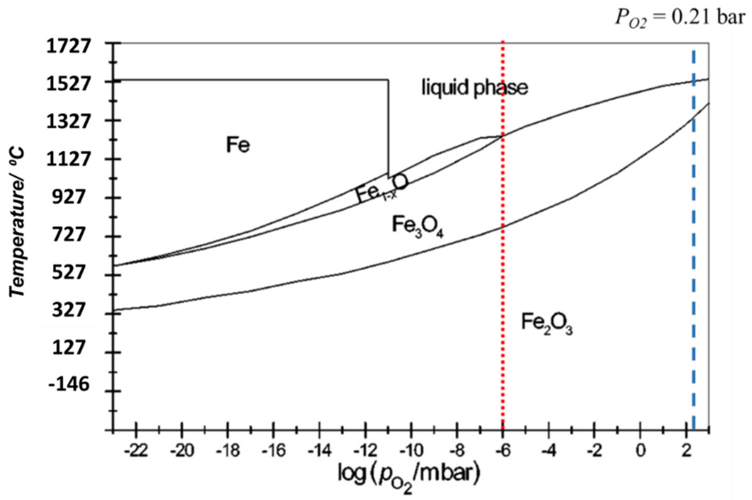
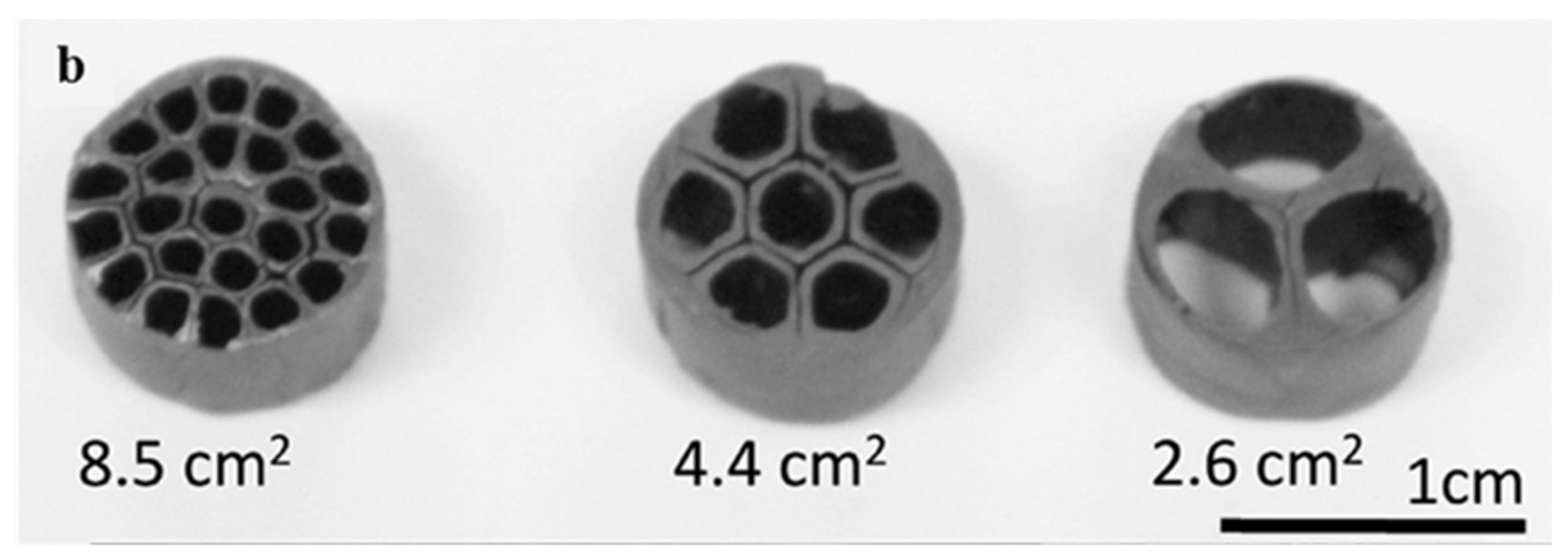
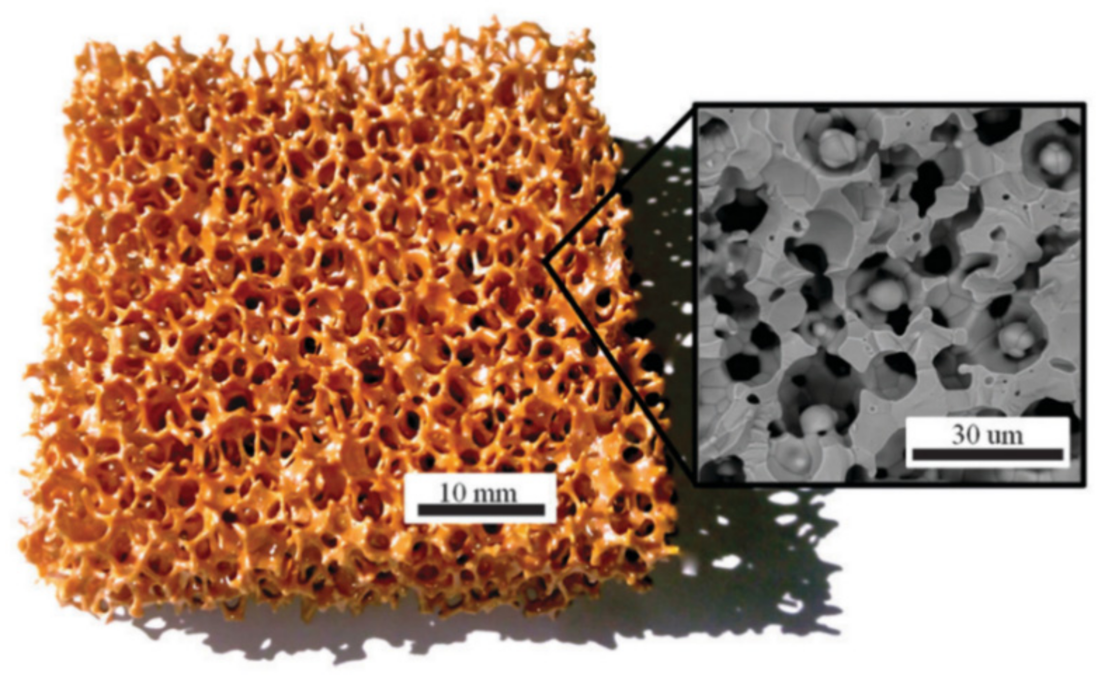
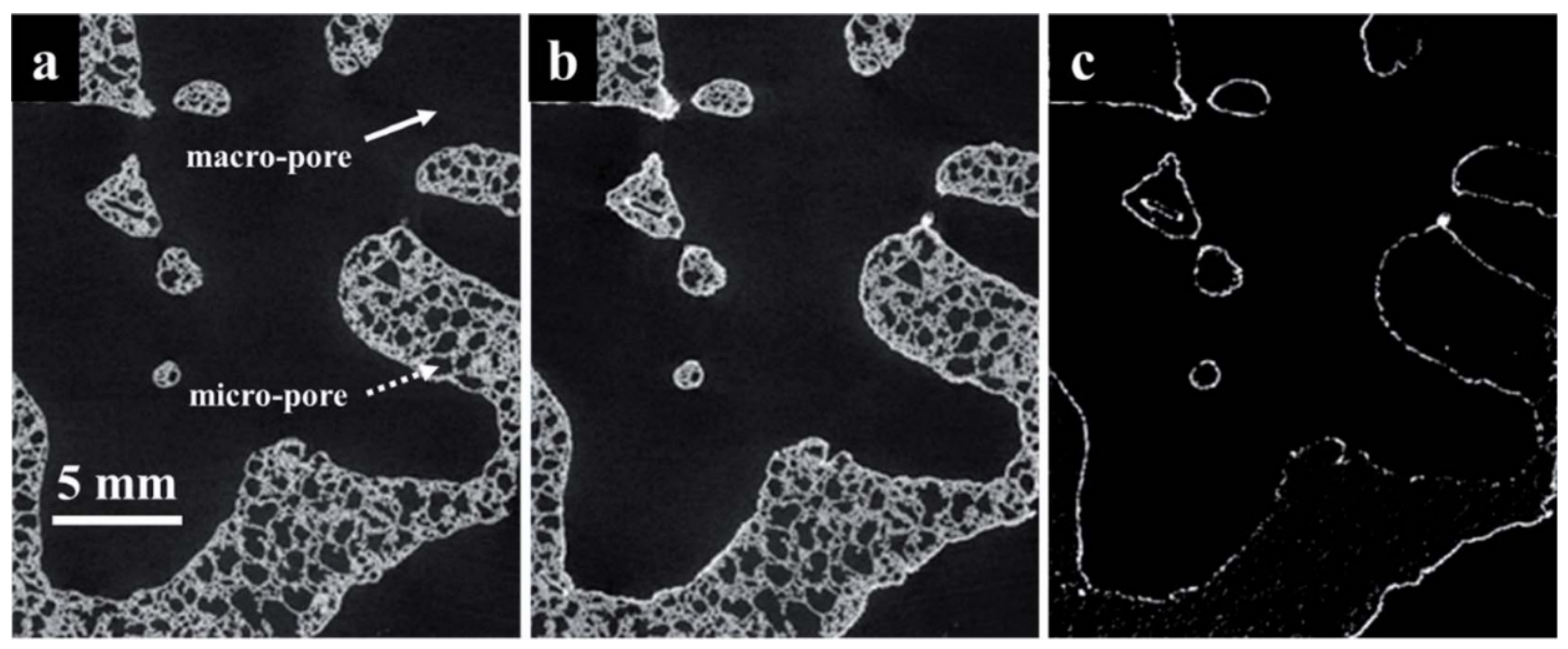
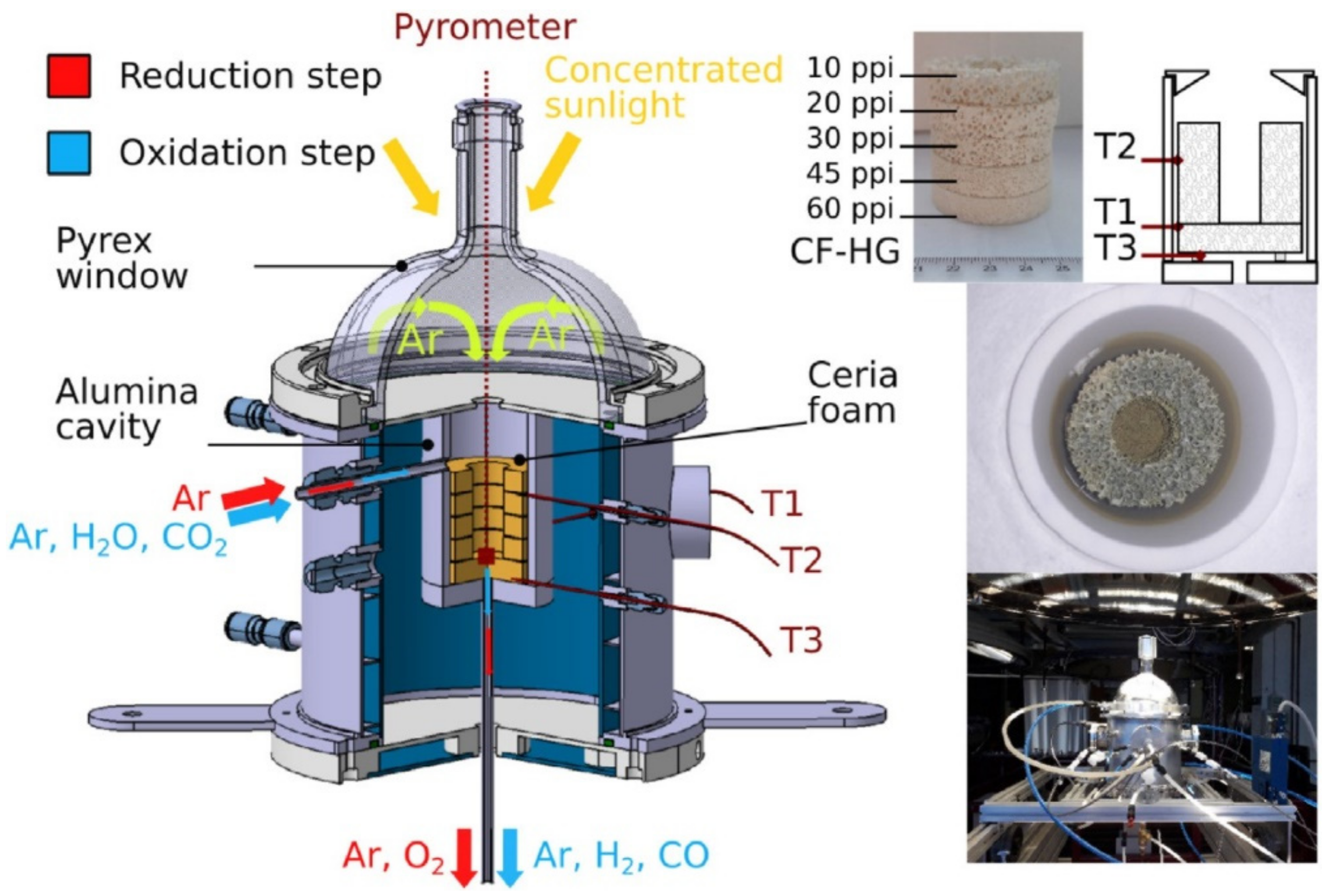
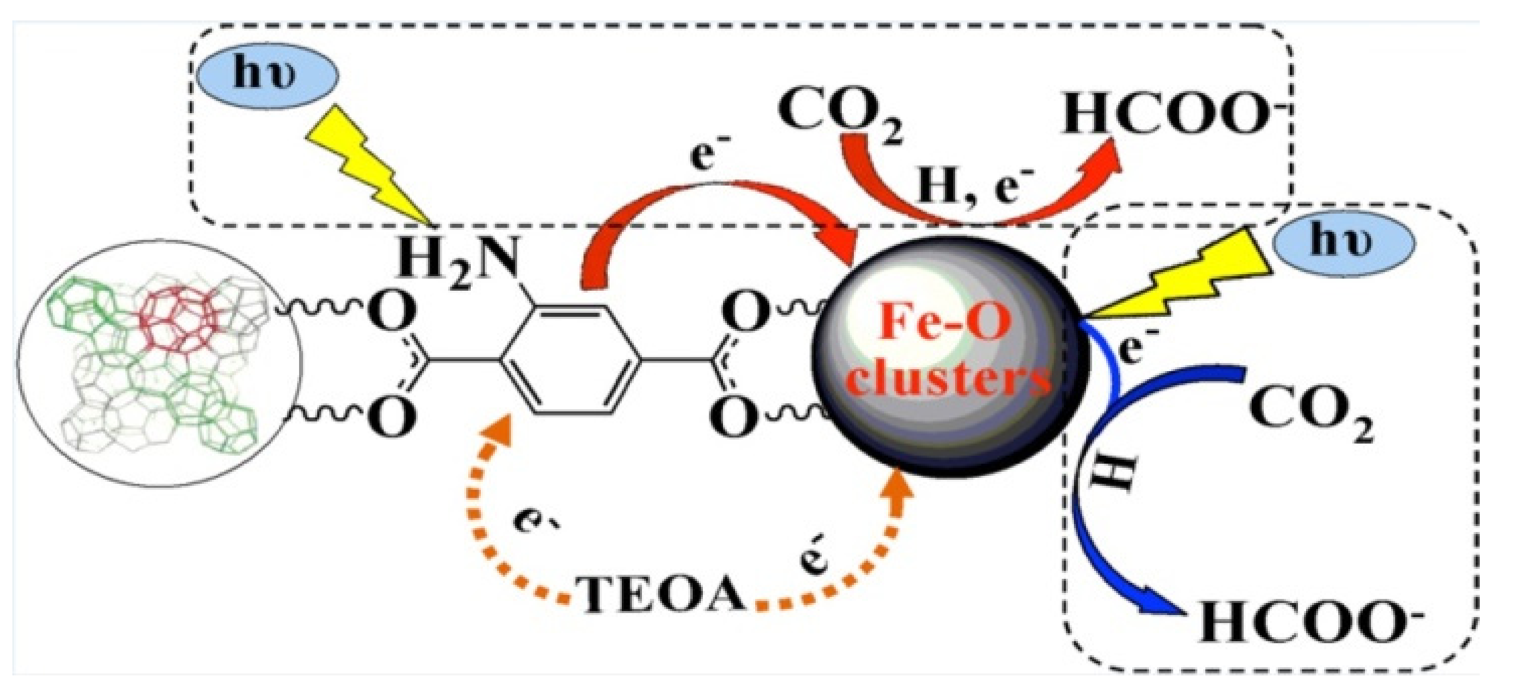
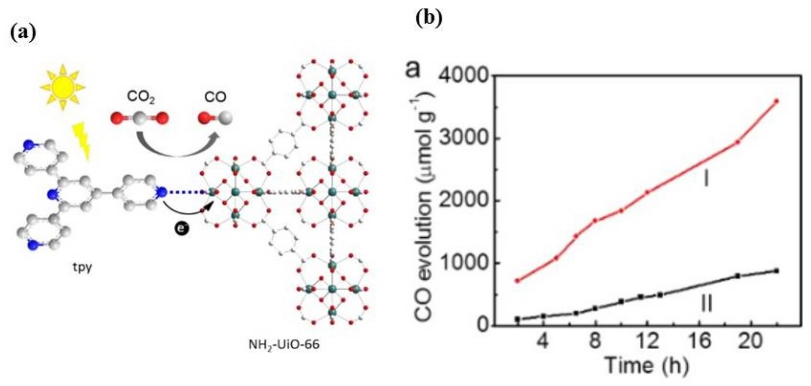
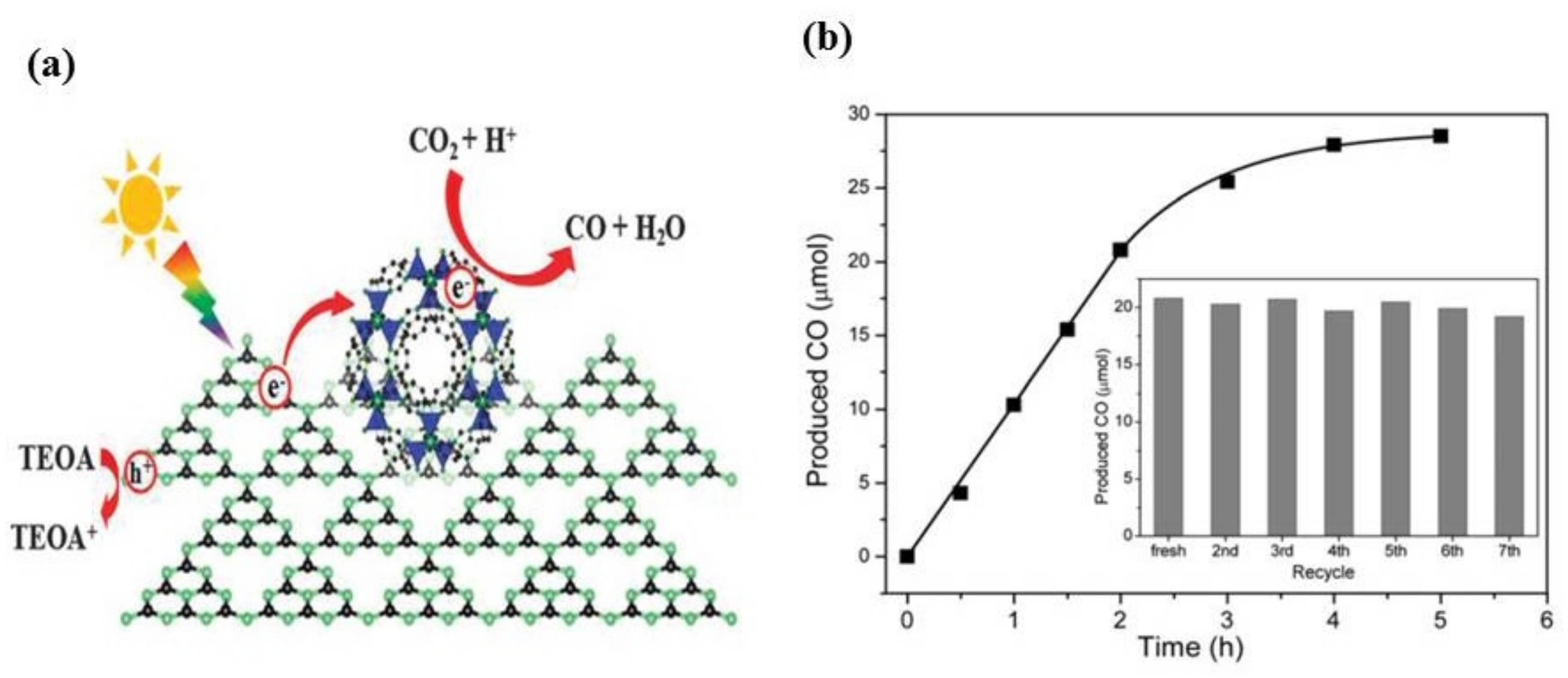
Figure 1. Anthropogenic CO2 sources and their contribution to the total CO2 emissions, adapted with permission from [6].
Energies 15 00063 g001
Figure 2. Industries that utilize CO2 as a feedstock, adapted with permission from [6].
Energies 15 00063 g002
Figure 3. The CDR process via H2O/CO2-splitting solar thermochemical cycle as a route for solar fuels.
Energies 15 00063 g003
Figure 4. Schematic representation of the 10-kW directly irradiated solar reactor used for thermal decomposition of ZnO to Zn and O2, developed at PSI [79].
Energies 15 00063 g004
Figure 5. The stability phase diagram of iron and oxygen [89].
Energies 15 00063 g005
Figure 6. Ce-O stability phase diagram in different partial pressures of O2 [127].
Energies 15 00063 g006
Figure 7. The HYDROSOL solar receiver-reactor used for water splitting showing the installment position and configuration of Mn/Zn-ferrite coated SiC honeycombs [141].
Energies 15 00063 g007
Figure 8. Polymer-based coextrusion ceramic honeycombs made from homogeneous composites of iron oxide and zirconia for the solar thermochemical dissociation of CO2 to CO [142].
Energies 15 00063 g008
Figure 9. (a) Ceria-coated RPCs consisting of a 20-mm thickness, 100-mm o.d. disk, and four 20-mm thicknesses, 60-mm i.d., 100-mm o.d. rings; (b) High-Flux Solar Simulator and the configuration of porous modules’ assembly at the Swiss Federal Institute of Technology (ETH) (bottom) [114].
Energies 15 00063 g009
Figure 10. Ceria RPC with dual-scale porosities; macro-porous structure with mm-sized pores that are ideal for reduction and µm-sized pores inside struts (SEM micrograph) responsible for oxidation reaction in the carbon dioxide splitting process [118].
Energies 15 00063 g010
Figure 11. (a) Schematic representation of the solar reactor for carbon dioxide splitting, comprising a windowed cavity-receiver containing a ceria RPC with dual pore sizes (mm- and μm-sized pores); (b) images of the front face of the solar reactor with the windowed aperture and its interior containing the octagonal ceria RPC structure insulated with a line of alumina [153].
Energies 15 00063 g011
Figure 12. The 2D tomogram slices of a porous SiC sample with dual-scale pore sizes including macro pores between struts and µm-sized micropores inside struts; (a) before; (b) after LCMA perovskite coating; and (c) after tomograms’ registration showing the perovskite mapping [136].
Energies 15 00063 g012
Figure 13. Schematic of the 1.5-kWth directly irradiated solar reactor equipped with a series of ceria RPCs with 10–60-ppi gradient pore sizes used for H2O or CO2 splitting [73].
Energies 15 00063 g013
Figure 14. Schematic of the overall photocatalytic reaction process for CO2 reduction (E+ Potential (V) vs. NHE at pH 7).
Energies 15 00063 g014
Figure 15. Schematic of the Surface photosensitizer.
Energies 15 00063 g015
Figure 16. CH4 photoreduction using Cr2O3 coupled with TiO2 photocatalysts showing (a) Cr2O3, (b) 400-Cr2O3@TiO2, (c) 550-Cr2O3@TiO2, (d) 700-Cr2O3@TiO2, and (e) 850-Cr2O3@TiO2 [218].
Energies 15 00063 g016
Figure 17. UV/Vis spectra of (a) MIL-125 (Ti) and (b) NH2-MIL-125 (Ti) [224].
Energies 15 00063 g017
Figure 18. Reaction pathways over NH2-MOFs (Fe) [226].
Energies 15 00063 g018
Figure 19. (a) Reaction pathway of CO2 photoreduction over NH2-UiO-66-tpy. N: blue, O: red, Zr: indigo, C: light gray. (b) CO evolution over NH2-UiO-66-tpy (I) and NH2-UiO-66 (II) as a function of time [22].
Energies 15 00063 g019
Figure 20. (a) Reaction pathway of the cooperation of Co-ZIF-9 and g-C3N4 for CO2 photoreduction under visible light illumination, (b) CO production from the Co-ZIF-9 and g-C3N4-based hybrid system as a function of the reaction time. Inset: recycling tests for CO2 photocatalytic reduction under visible light illumination [232].
Energies 15 00063 g020
Figure 21. (a) TEM and (b) SEM images of the synthesized Cu3(BTC)2@TiO2 core-shell structures [233].
Energies 15 00063 g021
Figure 22. Two proposed pathways for the CO2 photoreduction into CH4: formaldehyde (left) and carbene (right) [234].
Energies 15 00063 g022
Figure 23. SEM images of (a) GO, (b) NH2-rGO, (c) Al-PMOF, (d) NH2-rGO (5 wt %)/Al-PMOF, (e) NH2-rGO (15 wt %)/Al-PMOF, and (f) NH2-rGO (25 wt %)/Al-PMOF [238].
Energies 15 00063 g023
Figure 24. (a) Schematic of the structures of M-PMOFs (M = Co, Fe, Ni, Zn), (b) Faradaic efficiencies of M-PMOFs for CO [287].
Energies 15 00063 g024
Figure 25. (a) The produced CH4 ( A C H 4 volume at standard temperature and pressure) in 2 h as a function of potential, (b) the proposed reaction pathway for electroreduction of CO2 to CH4 on the Zn-MOF/CP cathode in ILs [293].
Energies 15 00063 g025
Figure 26. Proposed reaction pathways for electroconversion of CO2 into alcohols on OD Cu/C-1000 [301].
Energies 15 00063 g026
Table 1. The main CDR processes utilize CO2 as a feedstock.
CDR RouteMain Chemical ReactionsCommentsReferences
Dry reforming for syngas productionCO2 + CH4 ⇄ 2CO + 2H2
CO + H2O ⇄ CO2 + H2
Commercially available[12,31,32,33,34,35,36]
CO2 hydrogenation for methanol productionCO + 2H2 ⇄ CH3OH
CO2 + 3H2 ⇄ CH3OH + H2O
CO + H2O ⇄ CO2 + H2
Commercially available[37,38,39,40,41,42]
CO2 hydrogenation to DMECO2 + 3H2 ⇄ CH3OH + H2O
CO + 2H2 ⇄ CH3OH
CO + H2O ⇄ CO2 + H2
2CH3OH ⇄ CH3OCH3 + H2O
-[40,43,44,45]
Urea production2NH3 + CO2 ⇄ H2N-COONH4
H2N-COONH4 ⇄ (NH2)2CO + H2O
Commercially available[46,47,48]
Polyethercarbonate polyolsPropylene oxide (C3H6O) + CO2 → Polyethercarbonate polyolsCommercially available[49]
Fischer–Tropsch (FT) synthesis by dry reforming of natural gasn CO + 2nH2→(−CH2-) + nH2OCommercially available[12,36,50,51,52]
Solar thermochemicalMOoxidized + (∆H) → MOreduced + 1⁄2 O2 (g)
MOreduced + H2O/CO2(g)→MOoxidized + H2/CO(g) + (∆H)
Under development[19,53,54]
Photochemical
(During light irradiation, the energy of photons is absorbed. Excite electron/hole pairs are produced, which reduce and oxidize the chemical species over the surface of the photocatalyst.)
CO2 + 2H+ + 2e→HCO2HUnder development[55,56,57,58]
CO2 + 2H+ + 2e→CO + H2O
CO2 + 2H+ + 4e→HCHO + H2O
CO2 + 6H+ + 6e→CH3OH + H2O
CO2 + 8H+ + 8e→CH4 + 2H2O
2CO2 + 12H+ + 12e→C2H5OH + 3H2O
Electrochemical
(In this process, a chemical reaction occurs by the applied electrical current. It involves oxidation—reduction reactions where CO2 is reduced on the cathode and oxygen evolves at the anode.)
CO2 + 2H+ + 2e→HCO2HUnder development[59,60,61]
CO2 + 2H+ + 2e→CO + H2O
CO2 + 2H+ + 4e→HCHO + H2O
CO2 + 6H+ + 6e→CH3OH + H2O
CO2 + 8H+ + 8e→CH4 + 2H2O
2CO2 + 12H+ + 12e→C2H4 + 4H2O
Table 2. List of research items on the application of porous materials for solar thermochemical conversion processes.
YearPorous SupportRedOx Coating MaterialChemical ProcessPerformance References
1989Alumina honeycomb/foamRhCO2 methane reformingmore efficiency for honeycomb structure compared to foams[145,146]
2005re-crystallized SiC honeycombMn/Zn ferriteswater splittingconversion efficiency ~80% and hydrogen yield >90% at low oxidation temperatures (800 °C)[141,147]
2008c-YSZ / MPSZ foamFe3O4water splittingferrite conversion of 20–27% for a 10.5 wt% Fe3O4-coated porous MPSZ[137]
2009MPSZ foamm-ZrO2 supported NiFe2O4, Fe3O4water splittingferrite conversion of 24–76% for a 25 wt%
NiFe2O4 coating on porous MPSZ
[97]
2008 11:3 Co0.67Fe2.33O4/YSZ, Al2O3 and TiO2-water splittingunfavorable side reactions of ferrite with the YSZ supports and, thus, weak performance of the porous RedOx material[127,148]
2010cerium oxide (CeO2) monolith-water splitting/carbon dioxide splittingwith ƞsolar-to-fuel = 0.7–0.8% and the possibility of improvement through upscaling and removing the heat losses’ effects[70]
2011siliconized SiC monolithsFe/Zn mixed oxidewater splittingconversion efficiency ~30% and RedOx materials’ degradation due to zinc content volatilization and inhomogeneous temperature distribution[149]
MPSZ foamzirconia supported Fe3O4 or NiFe2O4water splittingmaximum ferrite conversion of 60% for NiFe2O4/m-ZrO2/MPSZ foam device[143]
2012 275 vol% YSZ and 25 vol% Fe2O3-carbon dioxide splittingyttria addition led to the oxygen conductivity improvement and Iron oxide conversion (max: 58%) and the stability of the CO production in consecutive RedOx cycles. The increasing of co-extruded honeycomb substrates’ surface area from ~2.6 to ~8.5 cm2 did not lead to a notable improvement in CO generation per unit volume[142]
porous ceria felt -water splitting/carbon dioxide splittingceria sublimation and deposition on reactor components were detected as the main technical challenges, which eventually were responsible for deterioration of the active material and, thus, reactor yield[150]
ceria RPC-carbon dioxide splittingwith mean ƞsolar-to-fuel = 1.73% and max ƞsolar-to-fuel = 3.53%,
a 17 times’ improvement in the fuel yield per cycle compared to ceria felt in previous study
[114]
20133DOM 3 CeO2, NOM 4 CeO2-carbon dioxide splittingmore structural stability and CO production rate (10-fold) of porous structures over non-porous ones in over 55 cycles[151]
2014ceria RPC with dual porosities-carbon dioxide splittinga 10 times higher yield for samples with porous struts (44% porosity) compared to samples with non-porous solid struts. The mean ηsolar-to-fuel of 1.72% was also detected in a 3.8-kW solar cavity receiver[118]
MPSZNiFe2O4/m-ZrO2 and CeO2water splittinglower yields of NiFe2O4/m-ZrO2/MPSZ compared to CeO2/MPSZ as a result of some sintering effects[138]
SiC, Ni, Cu foamsZrO2-supported CeO2methane reforming/water splittinghigher gas yields for the Ni and Cu foams than for SiC. The poor thermal conductivity of SiC foam was also responsible for CeO2 particle sintering and, thus, an overall efficiency decrement.[112]
2015porous ceria-carbon dioxide splittinghigh degree of reactivity (even after 2000 cycles) was reported [152]
2017ceria RPC with dual porosities-carbon dioxide splittingmolar CO2 conversion of 83% and ƞsolar-to-fuel = 5.25%[139,153]
2019Ceria RPC-water splitting/carbon dioxide splittingmax. ƞsolar-to-fuel = 5.22% while increasing methane flow rate and decreasing the reduction temperature will enhance the nonstoichiometry value and, thus, syngas yield[154]
2020SiC RPC with dual porositiesLa0.6Ca0.4Mn0..6Al0.4Oδ (LCMA)carbon dioxide splittingCO2 conversion with [CO%] = 3.2. A coagulation of smaller pores because of reaction between LCMA coating and SiC substrate was reported. The smallest pore size of 75 ppi delivered the highest CO yield of ca. 0.07 molg−1 LCMA and δ = 0.4[18,136]
ceria RPC (with gradient porosities 10–60 ppi)-water splitting/carbon dioxide splittingmax. ηsolar-to-fuel of ~7.5% after 64 cycles was measured with a high stability of the porous RedOx structures[73]
ceria RPCLa0.5Sr0.5Mn0.9Mg0.1O3 (LSMMg)water splitting/carbon dioxide splittingmax. ηsolar-to-fuel = 5.3 and the perovskite coating had just a positive effect on the reduction extent, which hindered oxidant gas (H2O or CO2) accessing the reactive ceria and can result in the poor re-oxidation compared to the pure, uncoated ceria RPC[14]
1. monolithic, honeycomb-type structures entirely made from RedOx materials’ rods 2. monolithic, honeycomb-type structures through polymer-based co-extrusion of ceramics 3. three-dimensionally macroporous 4. non-ordered macroporous.
Table 3. Results of CO2 photoreduction reaction under UVA 285-W/m2 irradiation [202].
Photoreactor.Photocatalyst.Product Formation Rate
(µmol gcat.−1 h−1)
Photoreactor Configuration
CH3OHCH4COEnergy
(Wh/m2)
AQEmax
(%)
SBTiO24.3--4.61.19
Cu-TiO222--
PBTiO259-315.25.7
Cu-TiO2473-
MTCu-TiO2-37.5405.30.063
Table 4. CO2 photoreduction performances after 3 h [216].
PhotocatalystProduction Yield (µmol g−1)Sel. for CO2 Reduction
(%)
Particle Size
(nm)
H2COCH4
CsPbBr3NC1.643.352.0690.316.4
CsPbBr3NC/a-TiO2(10)5.087.7310.1290.513.4
CsPbBr3NC/a-TiO2(20)4.3811.7120.1595.58.5
CsPbBr3NC/a-TiO2(30)4.428.0514.4093.77.8
CsPbBr3NC/a-TiO2(50)5.018.726.4787.45.9
Table 5. Photocatalytic CO2 reduction systems.
Reaction MediaLight SourceProductProduct Formation Rate
[µmol h−1g−1]
CommentReferences
TiO2-Based Photocatalyst
Metals and Non-metals Doping10 wt.% In/TiO2H2O vaporUV lightCH4244 [182]
CO81
C2H40.06
C2H62.78
C3H60.02
C3H80.02
TiO2 CH431
CO46
C2H40
C2H60
C3H60
C3H80
5 mol% Bi-TiO2H2O vaporUV lightCH434,000The Bi ion has appropriate conductivity and remarkable CO2 adsorption. Therefore, the presence of Bi in the Bi-TiO2 structure enhanced the number of adsorbed CO2 and H2O molecules.[251]
N3/TiO2waterUV lightCH3COCH352.6 [184]
Cu0.6N4/TiO2 33.2
N/TiO2-SG-PFE0.2 M NaOHUV lightCO0.2 [207]
CH40.0014
H20.012
TiO2/MgO-1%0.1 M NaOHUVC light
max = 253.7 nm)
HCOOH0.8125With increasing the amount of MgO, the catalytic efficiency decreased due to the full coverage of the TiO2 by MgO layers, consequently hindering the transferring of the photogenerated charge carriers at the TiO2 surface and thereby photoactivity was reduced.[252]
CH3COOH1.037
CH41.437
CO2.946
TNi1Bi3H2O vaporVisible lightCH42.113 [186]
Pt-TiO2/MWCNTH2O vaporVisible lightCH41.9 [194]
Pt-TiO2/SWCNT 0.7
Pt-TiO2/rGO 0.5
Pt-TiO2/AC 0.16
0.3% Mo- doped TiO2H2O vaporXe lamp
(300 W)
CO13.67CH4 selectivity increased with increasing Mo concentration to 0.3 wt.%. Thereafter, CH4 selectivity decreased with increasing Mo concentration. This was attributed to the decrease in electron-hole separation efficiency.[253]
CH416.33
Surface SensitizerNCQDs/TiO2H2O vaporSolarCO0.769 [208]
CH41.153
TiO2-[P4444]3[p-2,6-O-4-COO]TEOAVisible light
(λ > 420 nm)
CH43.52 [213]
H20.14
TiO2-[P4444]2[p-2-O-4-COO] CH40.19
H20.17
TiO2-[P4444] [p-2-O] CH40.1
H20.07
TiO2-[P4444] [p-4-COO] CH40.1
H20.06
Other SemiconductorsCsPbBr3NC/a-TiO2(20) CH46.72 [216]
CO3.9
H21.46
H20.55
Ti-NS/CNH2UV-Vis. lightCO2.04 [217]
Ti/ISO/CN CO1.55
Ti-NS/CNH2O CO0.8
H22.67
700-Cr2O3@TiO2H2OUV lightCH4167.69 [218]
CO0.488
ZnFe2O4/TiO2 (1:1)Na2S, Na2SO3, KOH in waterVisible lightCH3OH693.31 [219]
ZnFe2O4/TiO2 (1:2) 519.69
ZnFe2O4/TiO2 (2:1) 33.53
(20)TNPs-CN/450CH4Solar simulator
(λ = 320–780 nm)
CO4.71The sensitivity factors were investigated and implied the order of FC (Catalyst amount) > FE (Calcination temperature) > FB (CH4 to CO2 ratio) > FD (TNPs loading) > FA (Absolute pressure).[254]
(20)P25-CN/450 2.77
Bulk g-C3N4 2.275
MOF-Based Photocatalyst
NH2-Modified MOFsMIL-125 (Ti)MeCN/TEOA (5:1)Visible lightHCOO0 [224]
NH2-MIL-125 (Ti) 16.28
UiO-66(Zr)MeCN/TEOA (5:1)Visible lightHCOO0In addition to TEOA, benzyl alcohol, ethylenediaminetetraacetic, and methanol were utilized as reaction media and no HCOO was produced [225]
NH2-UiO-66(zr) 26.4
MIL-101 (Fe)MeCN/TEOA (5:1)Visible lightHCOO147.5MIL-101 (Fe) demonstrated the best photocatalytic performance due to the presence of coordination unsaturated Fe metal sites (CUSs) in its structure.[248]
NH2- MIL-101 (Fe) 445
MIL-53 (Fe) 74.25
NH2-MIL-53 (Fe) 116.25
MIL-88(Fe) 22.5
NH2-MIL-88(Fe) 75
NH2-UiO-66 (Zr)MeCN/TEOA (4:1)
BNAH (0.1 M)
Visible lightHCOO0Introducing Ti ions into UiO-66 structure created new energy levels and broader light absorption and also improved charge transfer, which increased photoactivity of the MOF structure.[255]
NH2-UiO-66 (Zr/Ti) 741
(NH2)2-UiO-66 (Zr/Ti) 1052.3 ± 54.7
NH2-UiO-66MeCN/TEOA (11:1)Simulate sunlight
(350 < λ < 780 nm)
CO34 [22]
NH2-UiO-66-tpy 209.2
Semiconductor-MOF compositeg-C3N4-Co-ZIF-9MeCN/H2O/TEOA (3:2:1)20 mg g-C3N4,
10 mg bpy,
1 mg MOF cocatalyst
Visible light
(λ > 420 nm)
CO495 [248]
H278.6
TiO2-Co-ZIF-9H2O vaporVisible light
(200 < λ < 900)
CO8.8Cocatalyst Co-ZIF-9 can facilitate CO2 adsorption and activation and also improve charge transfer.[256]
CH42.0
H22.6
Zn2GeO4-Zn-ZIF-8Na2SO3 (0.1 M)500 W Xe arc lampCH3OH0.22 [231]
TiO2@Cu3(BTC)2H2O vaporUV lightCH42.64 a [233]
HKUST-1/TiO2 CO256.3 aHKUST-1 was selected because of the high porosity and surface area, about 40.7% and over 600 m2/g, respectively. Introducing TiO2 into the HKUST-1 matrix increased CO2 photoreduction efficiency. Additionally, the hydrophilicity of HKUST-1 led to simultaneous adsorption of water (H2O), resulting in improving CO2 photoreduction processes.[257]
TiO2 CO11.48 a
TiO2-Mg-CPO-27H2O vaporUV lamps
(λ = 365)
CO4.09CPO-27-Mg was selected due to the superior CO2 adsorption capacity (about 35.2 wt.%) and consisted of great concentration of alkaline metal sites (Mg2+), which led to improved CO2 activation.[258]
CH42.35
CNNS-UiO-66 (Zr)MeCN/TEOA
(4:1)
Visible light
(400 < λ < 900)
CO2.9 [259]
CNNS 0.99
UiO-66 (Zr) 0
TiO2-NH2-UiO-66 (Zr) (18.5%) bCO2/H2
(1.5:1)
Visible light
λ > 325
CO4.24 [260]
TiO2 2.85
NH2-UiO-66 (Zr) 1.5
NH2-rGO (5 wt%)/Al-PMOFMeCN/TEOA
(5:1)
Visible lightHCOO685.6 [238]
Al-PMOF 165.3
TiO2/C@ZnCo-ZIF-L-Visible lightCO28.6 [239]
TiO2/C@Co-ZIF-L 22.7
TiO2/C@Zn-ZIF-L 18.7
TiO2/C 7.8
ZIF-L 0.36
PCN-224 (Cu)WaterXe lamp
(λ > 300)
CO3.72 [242]
6% PCN-224 (Cu)/TiO2 19.35
7.5% PCN-224 (Cu)/TiO2 26.78
10% PCN-224 (Cu)/TiO2 31.67
15% PCN-224 (Cu)/TiO2 37.21
30% PCN-224 (Cu)/TiO2 26.04
TiO2 0.82
Metal-MOF compositePt/NH2-MIL-125(Ti)MeCN/TEOA
(5:1)
Visible lightHCOO32.4 [245]
Au/NH2-MIL-125(Ti) 16.3
Ni0.87Mg0.13-MOF-74MeCN/TEOA
(5:1)
[Ru(bpy c)3] Cl2 as photosensitizer
Visible lightHCOO540 [20]
CO520
H22240
Ni0.75Mg0.25-MOF-74 HCOO640
CO460
H22610
Other form of MOF-based photocatalystZn/PMOFH2O vaporUV/Visible lightCH48.7 [250]
UiO-67-Cp*Rh d (5,5′-dcbpy) Cl2 (10%)MeCN/TEOA
(5:1)
Visible light
(λ > 415)
HCOO271 [249]
H2457
Al-PMOF embedded Cu2+H2O/TEA
(99:1)
Visible lightCH3OH262.6 (ppm h−1g−1)CO2 adsorbed chemically on the prepared photocatalyst, which led to bending the linear CO2 molecule, resulting in lower photoreduction barrier and subsequently improving the photocatalytic efficiency.[21]
Al-PMOF 37.5 (ppm h−1g−1)
Co/PMOFMeCN/TEOA
(5:1)
Visible lightHCOO23.21 [220]
a Product formation rate calculated by applying the mass of TiO2 (g), b the weight percentage content of NH2-UiO-66 in the semiconductor-NH2-UiO-66(Zr) composite, c bpy = 2,2′-bipyridine, d Cp* = pentamethylcyclopentadiene.
Table 6. The electrocatalytic performance of prepared catalysts for the CO2 reduction reaction (CO2RR) [306].
ElectrocatalystFECO2RR (%)FEisopropanol/FEother
Cu Mesh43.31.5
Cu Foil37.11.6
Cu-PCN62 800 °C8.21.9
Cu-PCN62 600 °C7.32
Ni-PCN62 800 °C29.10.4
Cu-HKUST-1 600 °C22.52.7
Ni-HKUST-1 600 °C75.10.1
Ni-HKUST-1 400 °C7.91.9
Table 7. Summary of the recently studied electrocatalysts for CO2 reduction reaction.
ElectrocatalystPotential (V vs. RHE)ElectrolyteProductFE (%)References
Co-PP@CNT−0.490.5 M NaHCO3CO98.3[309]
Cu-MOF-74 NPs−1.30.1 M KHCO3CH450[310]
CuBi12−0.210.5 M KHCO3CH3OH8.6[311]
C2H5OH28.3
alcohols36.9
H-M-G−0.460.1 M KHCO3CO96.9[312]
Ag1-Cu1.1 NDs−1.20.1 M KHCO3C2H3O21.25[313]
(CH2OH)20.34
C2H5OH4.3
C3H8O0.83
ZIF-A-LD/CB−1.10.1 M KHCO3CO90.57[314]
ZIF-7-A-LD/CB 53.7
Cu12Sn a−0.760.1 M KHCO3CO66.5[315]
Cu4Sn−0.97 HCOO56.77
Cu3Sn2−0.67 H250.33
Sn-OH-5.9 branches−1.6 V vs. Ag/AgCl0.1 M KClHCOOH82[316]
C193
Ni@NC-900−10.1 M KHCO3CO96[317]
w-CCG/CoPc-A hybrid−0.690.1 M KHCO3H211.4[318]
CO90.9
−0.79 H28.8
CO91.5
Cu2O/Cu@NC-800−6.80.1 M KHCO3HCOO70.5[16]
PdAg_2−0.270.1 M KHCO3HCOO94[319]
Sn-CHF (10 wt.%)−0.78 b0.1 M KHCO3CO8.91[320]
−0.98 b HCOO0.88
−0.48 b H287.72
−0.84 c CO48.36
−0.96 c HCOO8.94
−0.32 c H292.11
a Notably, the maximum obtained amount for each product is reported here. b CO2 flow rate: 1 sccm, the maximum amount of detected products in the liquid phase. c CO2 flow rate: 1 sccm, the maximum amount of detected products in the gas phase.
Publisher’s Note: MDPI stays neutral with regard to jurisdictional claims in published maps and institutional affiliations.

