Article

A Wirelessly Rechargeable AA Battery Using Electrodynamic Wireless Power Transmission

by
Spencer E. Smith
,
Miah A. Halim
,
Stasiu T. Chyczewski
,
Adrian A. Rendon-Hernandez
and
David P. Arnold
*
Interdisciplinary Microsystems Group (IMG), Department of Electrical and Computer Engineering, University of Florida, Gainesville, FL 32611, USA
*
Author to whom correspondence should be addressed.
Energies 2021, 14(9), 2368; https://doi.org/10.3390/en14092368
Submission received: 31 March 2021 / Revised: 16 April 2021 / Accepted: 19 April 2021 / Published: 22 April 2021
(This article belongs to the Special Issue Next Generation Wireless Charging System for Mobile Devices)

Abstract

:
We report the design, fabrication, and characterization of a prototype that meets the form, fit, and function of a household 1.5 V AA battery, but which can be wirelessly recharged without removal from the host device. The prototype system comprises a low-frequency electrodynamic wireless power transmission (EWPT) receiver, a lithium polymer energy storage cell, and a power management circuit (PMC), all contained within a 3D-printed package. The EWPT receiver and overall system are experimentally characterized using a 238 Hz sinusoidal magnetic charging field and either a 1000 µF electrolytic capacitor or a lithium polymer (LiPo) cell as the storage cell. The system demonstrates a minimal operating field as low as 50 µTrms (similar in magnitude to Earth’s magnetic field). At this minimum charging field, the prototype transfers a maximum dc current of 50 µA to the capacitor, corresponding to a power delivery of 118 µW. The power effectiveness of the power management system is approximately 49%; with power effectiveness defined as the ratio between actual output power and the maximum possible power the EWPT receiver can transfer to a pure resistive load at a given field strength.

Graphical Abstract

1. Introduction

Over the last century, batteries of all types have become an essential aspect of modern life. In general, batteries can be divided into two main categories: primary (single-use) and secondary (rechargeable) [1]. Due to an increased focus on sustainability in recent years, secondary batteries have seen an increase in development and applications [2]. From electric vehicles to mobile devices, secondary batteries act as a reliable and rechargeable source of energy for many electronic devices, increasing their overall versatility and portability [3,4]. However, recharging these batteries can prove cumbersome, since many modern devices require a charging cable to be plugged into a charging port. To overcome this hurdle, many researchers and companies are implementing wireless power transmission (WPT) to allow for wireless charging of mobile electronics, electric vehicles, toys, and medical implants [5,6,7,8,9].
In contrast to modern “high-tech” devices, where rechargeable batteries are permanently integrated within the system, enumerable other devices and products are powered by simple household batteries. Household batteries come in standardized form factors and voltages (e.g., AAA, AA, C, D, 9 V, etc.) and are available as either primary or secondary cells. A major drawback of rechargeable household batteries is that they typically must be removed from the product, placed on a charger for several hours, and then reinstalled in the product. This inconvenience is a major impediment to their utility in household products. But what if a household battery could be wirelessly recharged? What if it could be recharged without removal from the host electronic device? Besides the added convenience from a consumer standpoint, wireless charging capabilities could turn “old-tech” into “high-tech”. Additionally, eliminating the need for an openable and accessible battery compartment could yield better waterproofing of outdoor products, fewer restrictions on product form factors or coverings, and improved safety for toys and devices used by children.
Two prominent forms of near-field WPT are inductive power transmission (IPT) and electrodynamic wireless power transmission (EWPT). IPT involves using a time-varying magnetic field to inductively transfer energy between a transmitter coil and a receiver coil [10]. The main drawback to this method is the high frequency range (~0.1 MHz to 10 MHz) that most IPT devices require. Operations at these frequencies are severely limited, as higher frequency signals cannot penetrate conductive environments and lower magnetic field strengths must be used in accordance with IEEE health and safety guidelines [11,12]. In addition to limited magnetic field amplitudes at higher frequencies, these systems also tend to generate eddy (Foucault) currents within conductive media between the transmitter and the receiver. These eddy currents can lead to uncontrolled and undesired heating of the intervening media [13]. Due to the limitations of IPT systems, researchers have proposed and designed systems using EWPT that use an electromechanical approach to transfer energy [14,15,16,17,18,19,20,21,22]. In general, EWPT systems use time-varying magnetic fields to oscillate (translational or rotational) a permanent magnet within a receiver system. The motion of the oscillating magnet is converted into electricity via Faraday’s law, using a static coil around the magnet or via piezoelectric elements attached to the suspension structure. Both transduction schemes of EWPT systems operate at lower frequencies (<1 kHz), allowing for higher magnetic fields, better penetration through conductive media, and less parasitic heating [20].
To demonstrate the utility and opportunities afforded by an EWPT receiver (namely small receiver size and wireless transmission at modest distances through clutter), we report the design, fabrication, and testing of a first-generation, wirelessly rechargeable AA-sized battery prototype that can directly replace a conventional AA battery in a typical household electronic device. This prototype contains a 316 stainless steel EWPT receiver that charges an internal storage element via a power management unit. This EWPT receiver is inspired by a previous design [20,21], but has been modified to increase its reliability and power output. The significance of this work is twofold. First, we demonstrate a fully functioning wirelessly chargeable battery in a standard AA-battery form factor. Second, we characterize the AA-sized prototype and its internal components at low, safe magnetic charging fields, rather than absurdly high fields that will never be practical. Herein, we characterize and report the system operation at a point near its minimum operating condition, defined as the lowest magnetic field strength where the EWPT receiver can produce sufficient voltage and power for the power management circuitry to function. Since end use in a consumer setting contains unpredictable operating conditions, characterizing the AA-sized prototype in these low-end conditions is a better representation than the worse-case operating performance in a real-world setting, as opposed to operating at maximal performance conditions in a laboratory/controlled environment.

2. Materials and Methods

2.1. Design and Operation

The prototype system consists of four main components: the EWPT receiver, the energy storage element, the power management circuitry (PMC), and the AA-sized mechanical packaging (Figure 1). For wireless charging, the EWPT receiver is excited by an external time-varying magnetic field and generates an ac voltage and current. These ac signals are rectified and stabilized into a constant dc signal within the PMC, and these rectified signals are used to charge the energy storage element. The AA-sized packaging encloses the other components and has metal endcaps that connect the system to the external load. When an external load is connected, the PMC withdraws power from the energy storage element and delivers it to the load. Figure 2 shows a block diagram of the overall system and each block is defined below.

2.1.1. EWPT Receiver

The EWPT receiver consists of four main components: a 316 stainless steel platform, two silicon spacers, two rectangular neodymium (NdFeB) magnets, and two rectangular coils. At the center of the EWPT receiver design is the laser-machined steel suspension, which consists of a torsionally resonated mounting pad with two serpentine suspensions connecting the mounting pad to an external frame (Figure 3a). Two silicon spacers are located on each side of the central mounting pad, and a rectangular magnet (magnetized along its width) is located on top of each spacer. Two rectangular coils, electrically connected in series, are attached to the external frame, effectively surrounding the magnet. These coils are precision-manufactured with 44 AWG laminated copper wire, with 498 turns and a total electrical resistance of 125 Ω. Figure 3b,c depicts the completed EWPT receiver assembly, as well as an exploded view. The design uses a 0.1 mm-thick, 316 stainless steel platform, whereas a previously reported receiver [20,21] used a 0.3 mm-thick silicon platform; 316 stainless steel is used for its relatively high yield and ultimate strength, as well as it being a non-magnetic class of stainless steel.

2.1.2. Power Management Circuit

The EWPT receiver is capable of producing a sinusoidal open-circuit voltage on the scale of a few volts, peak to peak. However, the ac output power waveform needs to be rectified and regulated for storage on an energy storage element, as well as to supply the constant 1.5 V AA battery terminal voltage. This power management functionality is accomplished using a custom power management circuit (PMC), manufactured on a compact 2-layer printed circuit board (PCB). Figure 4 depicts the overall circuit diagram for the PMC. The initial stage in the circuit is the rectification stage. A full-bridge diode rectifier with four Schottky diodes (PMEG2020AEA) converts the ac output from the EWPT receiver into a dc output. Schottky diodes are used to minimize the forward voltage drop, as these diodes have a notable smaller drop (0.27 V per diode) than most standard silicon diodes (0.70 V per diode). The second stage of the PMC uses a BQ25570 (Texas Instrument Inc., Dallas, TX, USA) nano-power boost charger and buck converter. This integrated circuit chip takes the dc input from the rectifier and stores the energy on an external energy storage element at a programmable voltage level; it also features a built-in buck converter to regulate the voltage output to an external load. The energy storage voltage is programmed at 4.2 V (standard for lithium polymer batteries [23]), and the output voltage is set at 1.5 V to mimic the standard AA battery cell [24]. The 4.2 V voltage charges the storage element of the system and the 1.5 V voltage is supplied to an external load. Two different storage elements are used with the prototype: a 1000 µF electrolytic capacitor for benchtop testing and a lithium polymer (LiPo) cell (GM-NM30910 TUV UL1642, PowerStream Technology, Orem, UT, USA) in the completed AA-sized assembly for practical testing. The capacitor is used for benchtop testing instead of the LiPo cell because a LiPo cell has a nonlinear and hysteretic charging curve, and the charging current for lithium batteries is limited by various electrical, thermal, and aging constraints [25,26]. As such, a capacitive load allows for the EWPT receiver and the PMC to be characterized without these additional uncertainties present. This LiPo cell is chosen primarily based on its small size (3 mm × 9 mm × 10 mm) and its non-magnetic properties. As many LiPo cells contain ferromagnetic materials (cobalt within their cathodes and nickel foils), it was important to use a LiPo cell with minimal ferromagnetic properties so as not to impede the magnetic field delivered to the EWPT receiver.
In addition to the main PMC, a small mounting PCB is also used for many characterization experiments (Figure 5a). The EWPT receiver is glued into the center slot of the mounting PCB, and wires from the EWPT receiver’s coils are soldered to the board so the two coils are connected in series. This series connection is initially connected to two lead wires that are used to obtain voltage measurements from the EWPT receiver when the PMC board is not connected. To connect the mounting PCB to the main PMC board, the mounting PCB is cut and then glued to the edge of the main PMC board (Figure 5b). Lastly, a simple solder bridge electrically connects the EWPT receiver’s output terminals to the input terminals of the diode bridge.

2.1.3. 3D Printed AA-Sized Package

The final component is an AA-sized package that contains the EWPT receiver, PMC board, and storage element. The packaging consists of two parts: an internal structure that houses the main elements of the assemble in various slots/cut-outs and an outer casing that seals the entire system (Figure 6). The top of the internal structure contains a slot for the PMC board (with the EWPT receiver attached) to be inserted and press-fit into place. The EWPT receiver is enclosed near the base of the structure and held securely to prevent unwanted movement during transport and operation. A cut-out on the side of the internal structure is designed to hold the storage element. The function of the outer casing is to enclose and protect all the internal components of the system. Once the casing is slid over the internal structure, two metal end caps are glued onto each end of the casing to lock it into place. These metal end caps are connected to GND and OUT terminals of the PMC board via jumper wires. A small metal nub is soldered onto the positive end cap to mimic a commercial AA battery. This casing has a designed outer diameter of 14.3 mm and a designed length of 48 mm (without the metal end caps) to mimic the approximate size of a standard AA battery with an average outer diameter of 14 mm ± 0.5 mm and an average length of 50 mm ± 0.5 mm [24].

2.2. Fabrication and Assembly

2.2.1. EWPT Receiver Fabrication and Assembly

The stainless steel platform of the EWPT receiver was fabricated by laser cutting the serpentine pattern into a sheet of 316 stainless steel shim stock (203 mm × 305 mm × 0.1 mm). After the platform was cut, it was case-hardened using a Lindberg Tube Furnace with a forming gas (95% nitrogen gas and 5% hydrogen gas). The furnace was set at 550 °C ± 5 °C for 2 hours to form a nitrided case on all surfaces of the platform. This case hardening increased the strength and survivability of the steel platform when the EWPT receiver is exposed to high magnetic field strengths.
The silicon spacers (3.2 mm × 3.2 mm × 0.3 mm) were placed on each side of the central mounting pad to increase the distance from each magnet and the EWPT receiver’s center of mass. This distance ensured that the rotating magnets would not collide with the serpentine beams.
To assemble the EWPT receiver, the first step was to glue the silicon spacers to each side of the central mounting pad with cyanoacrylate glue. Once the glue dried, demagnetized NdFeB magnets were attached to the silicon spacers. The magnets were demagnetized for the assembly process because proper magnet alignment could not be obtained when handling the magnets in their magnetized states. A rectangular coil was then glued to each side of the external frame. The final assembly step was to magnetize the NdFeB magnets along their width using an Oersted Technology Magnetizer 340B.

2.2.2. AA-Sized Prototype Assembly and Wiring

To assemble the AA-sized prototype, the PMC board (with the EWPT receiver attached) was inserted into the 3D-printed internal structure. The orientation of the PMC/EWPT receiver subassembly is displayed in Figure 7a. The storage element was soldered to the battery charging terminals on the PMC, with the positive lead attached to the “BAT” terminal and the negative lead grounded. Two jumper wires were attached to the load terminals of the PMC, with one on the “OUT” terminal and the other to the common ground. Next, the storage element was placed within its designated cut-out on the internal structure, and then the outer casing was slid over the structure. The jumper wire attached to the “OUT” terminal was soldered to the positive end cap and the other jumper wire was soldered to the negative end-cap. Lastly, each end cap was glued to each end of the outer casing, completing the overall assembly (Figure 7b).

3. Experimental Results

Several different experiments were performed to characterize the overall AA-sized prototype and the EWPT receiver. For the EWPT receiver, these tests included a resonant frequency sweep, an optimum load sweep, and a power effectiveness calculation (with the effectiveness calculation performed with the EWPT receiver, the PMC board, and a 1000 µF capacitor). The basic functionality of the completed prototype (with the capacitor replaced with the LiPo cell) was qualitatively observed after benchtop characterization by installing the prototype within two electronic devices: an analog clock and a wireless computer mouse. Basic functionality tests confirmed whether the two electronic devices were fully functional and had wireless charging capabilities with the prototype installed.

3.1. Experimental Setup

The experimental setup for each test required a transmitter system to generate a time-varying magnetic field (Figure 8). This alternating magnetic field was generated using a Helmholtz coil pair (1000906 3B Scientific, Hamburg, Germany; 124 turns per coil; 300 mm outer diameter; 150 mm coil separation). An ac signal was generated by a waveform generator (DG1022A Rigol, Beaverton, OR, USA) and was fed into a power amplifier (K1 Crown, Los Angeles, CA, USA). The amplified ac signal was fed into the Helmholtz coil pair. The amplitude of magnetic field was linearly dependent on the amplitude of the current supplied to the coil. Initially, the magnetic field strength was measured directly with a gaussmeter (475DSP Lake Shore Cryotronics Inc., Westerville, OH, USA) connected to a transverse Hall probe (XHMMA-1482 Lake Shore Cryotronics Inc., Westerville, OH, USA) placed at the center of the Helmholtz coil pair. However, by using a current probe (TCP312A Tektronix, Beaverton, OR, USA) and a current probe amplifier (TCPA300 Tektronix, Beaverton, OR, USA), a calibration curve was generated to estimate the field strengths based on the supplied current amplitude. Lastly, a digital storage oscilloscope (DPO-2004 B Tektronix, Beaverton, OR, USA) was used to measure current and voltage waveforms for various inputs and outputs. Because the overall goal was to determine the low-end performance of the AA-sized prototype and its components, the transmitter system was used only to produce a low magnetic field strength of 50 µTrms; only slightly stronger than Earth’s magnetic field (on the surface). For magnetic fields with frequencies below 1 kHz, the maximum allowable (IEEE safety regulations) field strengths are 2.71 mTrms for controlled environments and 0.904 mTrms for the general public [12].

3.2. Resonant Frequency

The first test was a frequency sweep of the EWPT receiver to analyze its open circuit response, as well as to experimentally identify its torsional resonant frequency. Because an EWPT system operates by converting the mechanical motion of a resonating magnet into electricity, it was imperative to drive the system near one of its mechanical resonant frequencies (where angular displacement and angular velocities reach a local maxima) to maximize the output voltage and power. The EWPT receiver was designed to have a maximum output at its 1st torsional resonance mode, so this torsional resonant frequency needed to be experimentally determined to serve as the operating frequency for all subsequent experimentation. To generate the resonance curve, the EWPT receiver (disconnected from the PMC board) was placed at the center of the Helmholtz coil pair, and the open-circuit voltage generated by the receiver was measured at various frequencies. Based on the frequency response of the EWPT receiver (Figure 9), the torsional resonant frequency of the receiver was 238 Hz, which generated an open-circuit voltage of 1.66 Vrms. As shown in the resonant curve, the −3 dB bandwidth was 3.44 Hz, corresponding to a mechanical quality factor of 69.

3.3. Optimum Resistive Load

The next test was an optimum resistive load sweep to determine the theoretical maximum power that can be generated by the EWPT receiver. For this test, the EWPT receiver was connected to a resistance substitution box (RS-500 ELENCO, Wheeling, IL, USA) to apply a variable load resistance to the output of the receiver. The rms voltage ( V r m s ) across this resistive load ( R ) was measured, and then the average power ( P ) dissipated by the load was calculated using:
P = V r m s 2 R    
By plotting the calculated average power versus the load resistance, the maximum power and its corresponding resistive load value were determined (Figure 10). For the EWPT receiver, the optimum resistive load was 3.8 kΩ, which produced a load voltage of 954 mVrms and, thus, a maximum power of 240 µW. Although 3.8 kΩ was the optimum resistive load, we observed that the generated power was relatively constant, between 3.0 kΩ and 4.0 kΩ.

3.4. Power Effectiveness

The next characterization parameter of interest was the “effectiveness” of the power management circuitry. The effectiveness was a measure of the total output power from the PMC board compared to the theoretical maximum power the EWPT receiver could produce at its optimum load. The experimental setup required the transmitter system, the EWPT receiver, the PMC board, a 1000 µF capacitor, and a Digilent Analog Discovery 2 (DAD) data acquisition system. The DAD board served as a USB powered oscilloscope for obtaining voltage measurements. The digital storage oscilloscope could not be used in place of the DAD boards, as the digital storage oscilloscope had a common ground across its four channels, which would short-circuit the system if attempting to obtain simultaneous measurements from the EWPT receiver and the PMC. The 1000 µF electrolytic capacitor was connected to the battery terminals of the PMC board. The load terminals of the PMC were connected to the load resistance. Lastly, the EWPT receiver was connected to the input terminals of the PMC board and placed within a time-varying magnetic field to charge the capacitor.
To measure the PMC’s effectiveness, voltage measurements were obtained across the capacitor during its charge cycle, and a numeric approximation for the voltage curve, v ( t ) , across the capacitor was generated. Using the derivative of this voltage curve and the capacitance, C , then the current, i ( t ) , within the capacitor was calculated using the capacitor terminal using:
i ( t ) = C   d v ( t ) d t
From there, the dc power over the capacitor charge cycle, p ( t ) , was calculated using:
p ( t ) = v ( t ) · i ( t )
The voltage across the resistive load was measured and the dc power across the load was calculated by replacing V r m s with v ( t ) in Equation (1). The power across the resistive load and the power across the capacitor were summed to produce the overall output power from the PMC ( P P M C ). Lastly, the power effectiveness ( ϵ ) was calculated using:
ϵ = P P M C P m a x
where P m a x is the theoretical maximum power output from the EWPT receiver using an optimal/matched resistive load (instead of the power management electronics), which was separately determined to be 240 µW for 50 µTrms excitation field during the optimum resistive load sweep.
The effectiveness tests were performed with a 50 kΩ load, a 100 kΩ load, and no load (open circuit) connected to the output terminals of the PMC. For each resistive load, a curve fit was performed over the capacitor voltage measurements (Figure 11). The shape of the voltage curve was dependent on the task the BQ25570 chip was performing. The initial region was a slow-growing polynomial that converged to approximately 1.5 V. After the capacitor reached 1.5 V, the voltage grew much faster, with some fluctuations occurring due to the cold start process of the BQ25570 chip. The next major change occurred once the capacitor reached 3.3 V, as this was the programmed starting point for the PMC board to start outputting 1.5 V to the attached load. The final region occurred after the capacitor reached 4.2 V and began cyclically charging and discharging around 4.2 V. Lastly, the minimum load required for the PMC to charge the capacitor was found to be 23 kΩ. At this load, the capacitor would not charge beyond 3.3 V, as the 1.5 V output terminals were draining the capacitor at the same rate it was being charged.
The current to the capacitor was determined by curve fitting a numerical approximation to the voltage curves and taking their derivative. With the approximated current, the dc power curves for each resistive load were generated (Figure 12). The power effectiveness for each case was then calculated. Table 1 summarizes the results. A final power calculation was performed to calculate the power supplied to the transmitter system. This average power was calculated as 19.1 mW, which resulted in an end-to-end power transfer efficiency (PTE) for the overall system that was less than 1%. This efficiency is arguably quite low, but not unexpected, since the system characterization is performed near the minimal operating point of the electronics. Additionally, system efficiency can be significantly improved via further design optimizations of the transmitter, EWPT receiver, and the receiver PMC.

3.5. Prototype System Demonstration

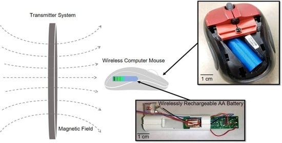
After characterizing the AA-sized prototype in a benchtop setting, the prototype was fully assembled and installed within two common electronic devices to study its basic functionality. These devices were a battery powered clock and a wireless computer mouse (Figure 13). Both devices were fully functional and exhibited wireless recharging capabilities while the prototype was installed in each host device.
In terms of dimensions, the AA-sized prototype had a final outer diameter of 14.2 mm and an overall length of 51.2 mm. The diameter was well within the desired range of 14 mm ± 0.5 mm, but the length was slightly outside the desired range of 50 mm ± 0.5 mm. This trivial error in length was due to underestimation of the thickness of the metal end caps on the final AA-sized prototype. Fortunately, the top of the internal structure has approximately 3 mm of excess length that can easily be reduced in future design iterations to lower the overall length into the desired range.

4. Conclusions

The overall goal of this series of experimentation was twofold. The first main objective was to demonstrate a fully functioning wirelessly chargeable battery in a standard AA-battery form factor. The completed prototype was able to produce 1.5 V across the metal end caps, which matched the 1.5 V standard potential for Alkaline AA batteries. The size of the prototype was approximately the same as a standard AA battery, with a final outer diameter of 14.2 mm and an overall length of 51.2 mm. Lastly, the prototype was used to power both a battery-powered clock and a wireless computer mouse. While installed in each host device, the prototype enabled each device to have wireless charging capabilities.
The second objective was to characterize the AA-sized prototype and its internal components at low, safe magnetic charging fields. In a very low magnetic field of 50 µTrms (5.5% of the maximum allowable for general public use) and near the minimal operating point of the electronics, the device was able to generate a maximum power output of 118 µW, with a power effectiveness of 49.3%. This power effectiveness showed that the power supplied to both the storage element and attached load was nearly half of the maximum potential power output from the EWPT receiver at this magnetic field strength. The power transfer efficiency for the overall prototype was low (<1%); however, for low-power applications, power efficiency may not be a primary design goal, as user experience, cost, and convenience may take a higher priority.
Regarding the EWPT receiver itself, the 316 stainless steel design was an overall improvement on prior designs. With a torsional resonant frequency of only 238 Hz, the stainless steel EWPT receiver produced a maximum power of 240 µW when connected to a 3.8 kΩ load. The prior design produced an average power of 102 µW and had a power density of 0.32 mW/cm3 at 50 µTrms. The 316 stainless steel design produced 235% more power, with a power density of 0.80 mW/cm3 for the same magnetic field strength. Normalizing these power densities by the magnetic field amplitude squared allows for direct comparison with devices tested at different field strengths. These key parameters for other EWPT receivers are tabulated in Table 2.

Author Contributions

Conceptualization, S.E.S., M.A.H. and S.T.C.; Data Curation, S.E.S.; Formal Analysis, S.E.S. and M.A.H.; Funding Acquisition, D.P.A.; Investigation, S.E.S.; Methodology, S.E.S. and S.T.C.; Project Administration, D.P.A.; Resources, S.E.S. and A.A.R.-H.; Software, S.E.S.; Supervision, M.A.H., A.A.R.-H. and D.P.A.; Validation, S.E.S., M.A.H. and S.T.C.; Visualization, S.E.S.; Writing—Original Draft, S.E.S.; Writing—Review & Editing, S.E.S., M.A.H., A.A.R.-H. and D.P.A. All authors have read and agreed to the published version of the manuscript.

Funding

This research was funded by the NSF I/UCRC on Multi-functional Integrated System Technology (MIST) Center (NSF Grant IIP-1439644, IIP-1439680, and IIP-1738752).

Conflicts of Interest

The authors declare no conflict of interest.

References

  1. Jafari, H.; Rahimpour, M.R. Pb Acid Batteries. In Rechargeable Batteries: History, Progress, and Applications, 1st ed.; Boddula, R., Pothu, I.R., Asiri, A.M., Eds.; Wiley: Hoboken, NJ, USA, 2020; pp. 17–39. [Google Scholar]
  2. Jeong, G.; Kim, Y.-U.; Kim, H.; Sohn, H.-J. Prospective materials and applications for Li secondary batteries. Energy Environ. Sci. 2011, 4, 1986–2002. [Google Scholar] [CrossRef]
  3. Pistoia, G. Lifetime Cost of Battery, Fuel-Cell, and Plug-in Hybrid Electric Vehicles. In Electric and Hybrid Vehicles, 1st ed.; Pistoia, G., Ed.; Elsevier: Amsterdam, The Netherlands, 2010. [Google Scholar]
  4. Scholey, N. Rechareable Batteries for Mobile Communications. In Proceedings of the IEE Colloquium on Radio Frequency and Design in Mobile Radio Transceivers, London, UK, 8 December 1994. [Google Scholar]
  5. Airiona. Available online: https://airiona.com/ (accessed on 30 March 2021).
  6. Cota: Real Wireless Power. Available online: https://www.ossia.com/cota/ (accessed on 30 March 2021).
  7. Lee, C.H.; Jung, G.; Shin, S.; Kim, Y. Design and Introduction of High Power Transfer System for Electrical Vehicles. In Proceedings of the 2013 IEEE International Conference on Intelligent Rail Transportation, Beijing, China, 30 August–1 September 2013; pp. 280–284. [Google Scholar]
  8. Al-Attar, A.; Attia, S.; Al-Bialy, A.; Abdelatif, E.N.; Al-Gazar, A.S.; Salem, A.; Badr, B.M. Wireless Power Transfer for Toys and Portable Devices. In Proceedings of the IEEE Conference on Power Electronics and Renewable Energy (CPERE), Aswan, Egypt, 23–25 October 2019; pp. 479–484. [Google Scholar]
  9. Lee, H.; Jung, S.; Huh, Y.; Kim, S.J. Wireless Power Receiver with Wide Dynamic Range for Biomedical Implants. In Proceedings of the 2019 IEEE Wireless Power Transfer Conference (WPTC), London, UK, 17–23 June 2019; pp. 241–244. [Google Scholar]
  10. Minnaert, B.; Stevens, N. Maximizing the Power Transfer for a Mixed Inductive and Capacitive Wireless Power Transfer System. In Proceedings of the 2018 IEEE Wireless Power Transfer Conference (WPTC), Montreal, QC, Canada, 3–7 June 2018; pp. 1–4. [Google Scholar]
  11. IEEE. Standard for Safety Levels with Respect to Human Exposure to Radio Frequency Electromagnetic Fields, 3 kHz to 300 GHz; IEEE Standard C95.1-2010; IEEE: Piscataway, NJ, USA, 2010; pp. 1–238. [Google Scholar]
  12. IEEE. Standard for Safety Levels with Respect to Human Exposure to Electromagnetic Fields, 0–3 kHz; IEEE Standard C95.6-2002; IEEE: Piscataway, NJ, USA, 2002; pp. 1–43. [Google Scholar]
  13. Yang, D.X.; Hu, Z.; Zhao, H.; Hu, H.F.; Sun, Y.Z.; Hou, B.J. Through-Metal-Wall Power Delivery and Data Transmissions for Enclosed Sensors: A Review. Sensors 2015, 15, 31581–31605. [Google Scholar] [CrossRef] [PubMed]
  14. Garraud, A.; Jimenez, J.D.; Garraud, N.; Arnold, D.P. Electrodynamic Wireless Power Transmission to Rotating Magnet Receivers. J. Phys. Conf. Ser. 2014, 557, 012136. [Google Scholar] [CrossRef] [Green Version]
  15. Garraud, N.; Garraud, A.; Munzer, D.; Althar, M.; Arnold, D.P. Modeling and Experimental Analysis of Rotating Magnet Receivers for Electrodynamic Wireless Power Transmission. J. Phys. D Appl. Phys. 2019, 52, 185501. [Google Scholar] [CrossRef]
  16. Halim, M.A.; Rendon-Hernandez, A.A.; Smith, S.E.; Arnold, D.P. A Chip-Sized Piezoelectric Receiver for Low-Frequency, Near-Field Wireless Power Transfer: Design, Modeling and Experimental Validation. Smart Mater. Struct. 2021, 30, 045011. [Google Scholar] [CrossRef]
  17. Truong, B.D.; Roundy, S. Wireless Power Transfer System with Center-Clamped Magneto-Mechano-Electric (MME) Receiver: Model Validation and Efficiency Investigation. Smart Mater. Struct. 2019, 28, 015004. [Google Scholar] [CrossRef] [Green Version]
  18. Liu, G.; Ci, P.; Dong, S. Energy Harvesting from Ambient Low-Frequency Magnetic Field using Magneto-Mechano-Electric Composite Cantilever. Appl. Phys. Lett. 2014, 104, 032908. [Google Scholar] [CrossRef]
  19. Garraud, N.; Alabi, D.; Varela, J.D.; Arnold, D.P.; Garraud, A. Microfabricated Electrodynamic Wireless Power Receiver for Bio-implants and Wearables. In Proceedings of the 2018 Solid-State Sensor and Actuator Workshop, Hilton Head Island, SC, USA, 3–7 June 2018; pp. 34–37. [Google Scholar]
  20. Halim, M.A.; Smith, S.E.; Samman, J.M.; Arnold, D.P. A High-Performance Electrodynamic Micro-Receiver for Low-Frequency Wireless Power Transfer. In Proceedings of the 2020 IEEE 33rd International Conference on Micro Electro Mechanical Systems (MEMS), Vancouver, BC, Canada, 18–22 January 2020; pp. 590–593. [Google Scholar]
  21. Halim, M.A.; Rendon-Hernandez, A.A.; Smith, S.E.; Samman, J.M.; Garraud, N.; Arnold, D.P. Miniature Electrodynamic Wireless Power Transmission Receiver Using a Micromachined Silicon Suspension. JMEMS 2021, 30, 144–155. [Google Scholar]
  22. Smith, S.E.; Halim, M.A.; Rendon-Hernandez, A.A.; Arnold, D.P. Dual-Transduction Electromechanical Receiver for Near-Field Wireless Power Transmission. In Proceedings of the 2021 IEEE 34th International Conference on Micro Electro Mechanical Systems (MEMS), Gainesville, FL, USA, 25–29 January 2021; pp. 38–41. [Google Scholar]
  23. Kumar, R.V.; Sarakonsri, T. Lithium-Ion Batteries. In High Energy Density Lithium Batteries: Materials, Engineering, Applications, 1st ed.; Aifantis, K.E., Hackney, S.A., Kumar, R.V., Eds.; Wiley-VCH: Hoboken, NJ, USA, 2010; pp. 70–74. [Google Scholar]
  24. ENERGIZER E91 Product Datasheet. Available online: https://data.energizer.com/pdfs/e91.pdf (accessed on 28 February 2021).
  25. Wei, Z.; Zhao, J.; Xiong, R.; Dong, G.; Pou, J.; Tseng, K.J. Online Estimation of Power Capacity with Noise Effect Attenuation for Lithium-Ion Battery. IEEE Trans. Ind. Electron. 2019, 66, 5724–5735. [Google Scholar] [CrossRef]
  26. Wei, Z.; Quan, Z.; Wu, J.; Li, Y.; Pou, J.; Zhong, H. Deep Deterministic Policy Gradient-DRL Enabled Multiphysics-Constrained Fast Charging of Lithium-Ion Battery. IEEE Trans. Ind. Electron. Accepted.
Figure 1. Exploded view of the AA battery prototype.
Energies 14 02368 g001
Figure 2. Block schematic of the overall design and operation of the AA-sized prototype.
Energies 14 02368 g002
Figure 3. Schematics of (a) the 316 stainless steel platform within the EWPT receiver, (b) complete EWPT receiver assembly, and (c) exploded view of the EWPT receiver.
Energies 14 02368 g003
Figure 4. (a) Circuit diagram of the PMC and (b) its schematic layout on a 2-layer PCB.
Energies 14 02368 g004
Figure 5. (a) Mounting PCB with micro-receiver compared to a US quarter dollar (USD 0.25). (b) PMC board compared to a US quarter dollar (c) Full micro-receiver and PMC subassembly.
Energies 14 02368 g005
Figure 6. Schematics of the (a) 3D-printed internal structure and (b) 3D-printed outer casing.
Energies 14 02368 g006
Figure 7. (a) Orientation of the PMC/EWPT receiver subassembly and pad labels, and (b) completed AA-sized prototype next to a commercially available Alkaline AA battery.
Energies 14 02368 g007
Figure 8. Photograph of the experimental setup to characterize the wirelessly rechargeable AA-sized prototype.
Energies 14 02368 g008
Figure 9. Frequency response of the open circuit EWPT receiver at 50 µTrms.
Energies 14 02368 g009
Figure 10. Average power and rms voltage versus resistive load for the EWPT receiver in a 50 µTrms magnetic field.
Energies 14 02368 g010
Figure 11. DC voltage across the 1000 µF capacitor for various load conditions.
Energies 14 02368 g011
Figure 12. DC power across the 1000 µF capacitor for various load conditions.
Energies 14 02368 g012
Figure 13. (a) Prototype in front of the battery powered clock and, (b) prototype installed within a wireless computer mouse (different 3D printed package but identical internals).
Energies 14 02368 g013
Table 1. Charge times, dc powers, and power effectiveness for charging a 1000 µF capacitor.
Parameter50 kΩ Load100 kΩ LoadOpen Circuit
Charge time (min)7.387.046.48
Max PMC DC power (µW)116.6116.7118.3
Max power effectiveness (%)48.648.649.3
Table 2. Performance comparison between various EWPT receivers.
Receiver DesignFrequency (Hz)Avg. Power (µW)NPD 1 (mW/mT2 cm3)
This work238240318.6
[17]259.84.931.2
[18]95.614.41.17
[20,21]821102129.6
[22]734.65206.5
1 Normalized power density for devices placed at the centroid of a Helmholtz coil pair.
Publisher’s Note: MDPI stays neutral with regard to jurisdictional claims in published maps and institutional affiliations.

