
A Parameter Independent Stator Current Space-Vector Reference Frame-Based Sensorless IPMSM Drive Using Sliding Mode Control

 ,
,  and
and
Abstract
: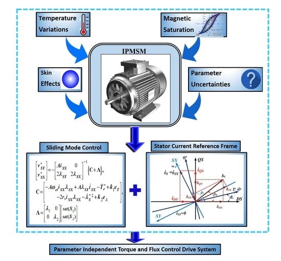
1. Introduction
2. Analytical Approach
2.1. Sliding Mode Control of Ipmsm
2.2. Ipmsm Rotor-Speed Estimation
2.3. Stator Resistance Estimation
3. Results
3.1. Simulation Results
3.2. Experimental Methodology
3.2.1. Experimental Setup
- Generating the switching pattern of IGBT switches based on the symmetrical SV-PWM technique;
- Giving a helpful dead time in the so-called switching patterns of power switches;
- Generating the synchronizing signal for data transmission between the PC and hardware;
- Shutting down the inverter emergency conditions to stimulate over current or PC hanging states.
3.2.2. Experimental Results
4. Conclusions
Author Contributions
Funding
Institutional Review Board Statement
Informed Consent Statement
Data Availability Statement
Conflicts of Interest
References
- Soleimani, J.; Vahedi, A.; Ejlali, A.; Bafghi, M.B. Study on interior permanent magnet synchronous motors for hybrid electric vehicle traction drive application considering permanent magnet type and temperature. Turk. J. Electr. Eng. Comput. Sci. 2014, 22, 1517–1527. [Google Scholar] [CrossRef]
- Ancuti, M.C.; Tutelea, L.; Andreescu, G.D.; Blaabjerg, F.; Lascu, C.; Boldea, I. Practical wide-speed-range sensorless control system for permanent magnet reluctance synchronous motor drives via active flux model. Electr. Power Compon. Syst. 2014, 42, 91–102. [Google Scholar] [CrossRef]
- Chen, Y.; Liu, T.H.; Hsiao, C.F.; Lin, C.K. Implementation of adaptive inverse controller for an interior permanent magnet synchronous motor adjustable speed drive system based on predictive current control. IET Electr. Power Appl. 2014, 9, 60–70. [Google Scholar] [CrossRef]
- Tang, L.; Zhong, L.; Rahman, M.F.; Hu, Y. A novel direct torque control for interior permanent-magnet synchronous machine drive with low ripple in torque and flux-a speed-sensorless approach. IEEE Trans. Ind. Appl. 2003, 39, 1748–1756. [Google Scholar] [CrossRef]
- Inoue, Y.; Morimoto, S.; Sanada, M. Examination and linearization of torque control system for direct torque controlled IPMSM. IEEE Trans. Ind. Appl. 2009, 46, 159–166. [Google Scholar] [CrossRef]
- Andreescu, G.D.; Pitic, C.I.; Blaabjerg, F.; Boldea, I. Combined flux observer with signal injection enhancement for wide speed range sensorless direct torque control of IPMSM drives. IEEE Trans. Energy Convers. 2008, 23, 393–402. [Google Scholar] [CrossRef]
- Foo, G.; Rahman, M.F. Sensorless direct torque and flux-controlled IPM synchronous motor drive at very low speed without signal injection. IEEE Trans. Ind. Electron. 2009, 57, 395–403. [Google Scholar] [CrossRef]
- Lourde, R.M.; Umanand, L.; Rao, N.J. Shaft sensorless vector controlled PMSM servo drive using reduced order speed observer. IETE J. Res. 2000, 46, 77–86. [Google Scholar] [CrossRef]
- Zarchi, H.A.; Soltani, J.; Markadeh, G.A. Adaptive input–output feedback-linearization-based torque control of synchronous reluctance motor without mechanical sensor. IEEE Trans. Ind. Electron. 2009, 57, 375–384. [Google Scholar] [CrossRef]
- Na, R.; Wang, X.; Cao, Y.; Mao, L. Adaptive Input-Output Feedback Linearization control for IPMSM using Maximum Torque per Ampere strategy. In Proceedings of the 2011 6th International Forum on Strategic Technology, Harbin, China, 22–24 August 2011; Volume 2, pp. 684–689. [Google Scholar]
- Lin, C.K.; Liu, T.H.; Yang, S.H. Nonlinear position controller design with input–output linearisation technique for an interior permanent magnet synchronous motor control system. IET Power Electron. 2008, 1, 14–26. [Google Scholar] [CrossRef]
- Vittek, J.; Dodds, S.J.; Bris, P.; Stulrajter, M.; Makys, P. Experimental verification of chattering free sliding mode control of the drive position employing PMSM. J. Electr. Eng. -Bratisl. 2008, 59, 139. [Google Scholar]
- Ahmed, M.; Karim, F.M.; Abdelkader, M.; Abdelber, B. Input output linearization and sliding mode control of a permanent magnet synchronous machine fed by a three levels inverter. J. Electr. Eng. 2006, 57, 205–210. [Google Scholar]
- Fang, C.H.; Huang, C.M.; Lin, S.K. Adaptive sliding-mode torque control of a PM synchronous motor. IEE Proc. -Electr. Power Appl. 2002, 149, 228–236. [Google Scholar] [CrossRef]
- Mishra, J.; Wang, L.; Zhu, Y.; Yu, X.; Jalili, M. A Novel Mixed Cascade Finite-Time Switching Control Design for Induction Motor. IEEE Trans. Ind. Electron. 2019, 66, 1172–1181. [Google Scholar] [CrossRef]
- Wang, L.; Mishra, J.; Zhu, Y.; Yu, X. An Improved Sliding-Mode Current Control of Induction Machine in Presence of Voltage Constraints. IEEE Trans. Ind. Inform. 2020, 16, 1182–1191. [Google Scholar] [CrossRef]
- Kaynak, O.; Erbatur, K.; Ertugnrl, M. The fusion of computationally intelligent methodologies and sliding-mode control-a survey. IEEE Trans. Ind. Electron. 2001, 48, 4–17. [Google Scholar] [CrossRef]
- Feng, Y.; Yu, X.; Han, F. High-order terminal sliding-mode observer for parameter estimation of a permanent-magnet synchronous motor. IEEE Trans. Ind. Electron. 2012, 60, 4272–4280. [Google Scholar] [CrossRef]
- Wang, G.; Li, Z.; Zhang, G.; Yu, Y.; Xu, D. Quadrature PLL-based high-order sliding-mode observer for IPMSM sensorless control with online MTPA control strategy. IEEE Trans. Energy Convers. 2012, 28, 214–224. [Google Scholar] [CrossRef]
- Uddin, M.N.; Rebeiro, R.S. Online efficiency optimization of a fuzzy-logic-controller-based IPMSM drive. IEEE Trans. Ind. Appl. 2010, 47, 1043–1050. [Google Scholar] [CrossRef]
- Lee, Y.; Sul, S.K. Model-based sensorless control of an IPMSM with enhanced robustness against load disturbances based on position and speed estimator using a speed error. IEEE Trans. Ind. Appl. 2017, 54, 1448–1459. [Google Scholar] [CrossRef]
- Lin, F.J.; Liu, Y.T.; Yu, W.A. Power perturbation based MTPA with an online tuning speed controller for an IPMSM drive system. IEEE Trans. Ind. Electron. 2017, 65, 3677–3687. [Google Scholar] [CrossRef]
- Wu, X.; Huang, S.; Liu, K.; Lu, K.; Hu, Y.; Pan, W.; Peng, X. Enhanced position sensorless control using bilinear recursive least squares adaptive filter for interior permanent magnet synchronous motor. IEEE Trans. Power Electron. 2019, 35, 681–698. [Google Scholar] [CrossRef]
- Messali, A.; Hamida, M.A.; Ghanes, M.; Koteich, M. Estimation Procedure Based on Less Filtering and Robust Tracking for a Self-Sensing Control of IPMSM. IEEE Trans. Ind. Electron. 2020, 68, 2865–2875. [Google Scholar] [CrossRef]
- Najjar-Khodabakhsh, A.; Soltani, J. MTPA control of mechanical sensorless IPMSM based on adaptive nonlinear control. ISA Trans. 2016, 61, 348–356. [Google Scholar] [CrossRef] [PubMed]
- Najjar-Khodabakhsh, A.; Soltani, J. Implementation of sensorless IPMSM drive using the stator current space vector orientation reference frame. COMPEL Int. J. Comput. Math. Electr. Electron. Eng. 2016, 35, 1237–1256. [Google Scholar] [CrossRef]
- Moradian, M.; Soltani, J.; Najjar-Khodabakhsh, A.; Markadeh, G.A. Adaptive torque and flux control of sensorless IPMSM drive in the stator flux field oriented reference frame. IEEE Trans. Ind. Inform. 2018, 15, 205–212. [Google Scholar] [CrossRef]
- Park, D.M.; Kim, K.H. Parameter-independent online compensation scheme for dead time and inverter nonlinearity in IPMSM drive through waveform analysis. IEEE Trans. Ind. Electron. 2013, 61, 701–707. [Google Scholar] [CrossRef]
- Vas, P. Sensorless Vector and Direct Torque Control; Oxford University Press: Oxford, UK, 1998. [Google Scholar]
- Marino, R.; Tomei, P. Nonlinear Control Design: Geometric; Adaptive and Robust; Prentice Hall International (UK) Limited: London, UK, 1995. [Google Scholar]


| P (Pole Pairs) | 2 |
|---|---|
| rs | 21.5 Ω |
| λm | 0.493 Wb |
| Ld | 0.3 H |
| Lq | 0.8 H |
| Pn | 300 W |
| Is | 1.1 A |
| f | 50 Hz |
| PI (Speed Controller) | KP = 0.05 | KI = 0.15 |
| Positive constant | K1 = 375 | K2 = 890 |
| SMC positive control gains | λ1 = 1.55 | λ2= 1.55 |
Publisher’s Note: MDPI stays neutral with regard to jurisdictional claims in published maps and institutional affiliations. |
© 2021 by the authors. Licensee MDPI, Basel, Switzerland. This article is an open access article distributed under the terms and conditions of the Creative Commons Attribution (CC BY) license (https://creativecommons.org/licenses/by/4.0/).
Share and Cite
Moradian, M.; Soltani, J.; Benbouzid, M.; Najjar-Khodabakhsh, A. A Parameter Independent Stator Current Space-Vector Reference Frame-Based Sensorless IPMSM Drive Using Sliding Mode Control. Energies 2021, 14, 2365. https://doi.org/10.3390/en14092365
Moradian M, Soltani J, Benbouzid M, Najjar-Khodabakhsh A. A Parameter Independent Stator Current Space-Vector Reference Frame-Based Sensorless IPMSM Drive Using Sliding Mode Control. Energies. 2021; 14(9):2365. https://doi.org/10.3390/en14092365
Chicago/Turabian StyleMoradian, Mohammadreza, Jafar Soltani, Mohamed Benbouzid, and Abbas Najjar-Khodabakhsh. 2021. "A Parameter Independent Stator Current Space-Vector Reference Frame-Based Sensorless IPMSM Drive Using Sliding Mode Control" Energies 14, no. 9: 2365. https://doi.org/10.3390/en14092365