Article

Influence of Thermal Aging on the Combustion Characteristics of Cables in Nuclear Power Plants

1
Department of Safety Engineering, Incheon National University (INU), Incheon 22012, Korea
2
Department of Reactor System Evaluation, Korea Institute of Nuclear Safety (KINS), Daejeon 34142, Korea
3
Research Institute for Engineering and Technology, Incheon National University (INU), Incheon 22012, Korea
*
Author to whom correspondence should be addressed.
Energies 2021, 14(7), 2003; https://doi.org/10.3390/en14072003
Submission received: 19 February 2021 / Revised: 24 March 2021 / Accepted: 31 March 2021 / Published: 5 April 2021
(This article belongs to the Section J: Thermal Management)

Abstract

:
In this study, the combustion characteristics and emission of toxic gases of a non-class 1E cable in a nuclear power plant were investigated with respect to the aging period. A thermal accelerated aging method was applied using the Arrhenius equation with the activation energy of the cables and the aging periods of the cables set to zero, 10, 20, 30 and 40 years old by considering the lifetime of a nuclear power plant. According to ISO 5660-1 and ISO 19702, the cone calorimeter Fourier transform infrared spectroscopy test was performed to analyze the combustion characteristics and emission toxicity. In addition, scanning electron microscopy and an energy dispersive X-ray spectrometer were used to examine the change in the surface of the sheath and insulation of the cables according to the aging periods. To compare quantitative fire risks at an early period, the fire performance index (FPI) and fire growth index (FGI) are derived from the test results of the ignition time, peak heat release rate (PHRR) and time to PHRR (tPHRR). When comparing FPI and FGI, the fire risks decreased as the aging period increased, which means that early fire risks may be alleviated through the devolatilization of both the sheath and insulation of the cables. However, when comparing heat release and mass loss, which represent the fire risk at the mid and late period, fire intensity and severity increased with the aging period. The emission of toxic gases coincided with the results obtained from the heat release rate, which confirms that the toxicity of non-aged cables is higher than that of aged cables. From the results, it can be concluded that the aging period significantly affects both the combustion characteristics and toxicity of the emission gas. Therefore, cable degradation with aging should be considered when setting up reinforced safety codes and standards for cables and planning proper operation procedures for nuclear power plants.

1. Introduction

In recent years, when a nuclear power plant (NPP) has been developed for the third generation, the design life time of NPPs has been increased to 60 years [1]. Previously designed second generation NPPs intend to extend the design lifetime of the original 40 years according to the long-term operation (LTO). Therefore, studies on the aging degradation of systems, structures and components (SSCs) for predicting their lifetime have been continuously conducted [2]. Cables, one of the components, are available in various types and span several thousand kilometers [3,4] for power supply and signal transmission. As cables are widely installed and difficult to replace regularly, it is necessary to conduct normal operating functions during the design lifetime of NPPs. In particular, cables consisting of a polymeric insulation and sheath are classified as combustible materials and must maintain a certain level of flame retardant performance during the design lifetime of NPPs. However, cables degrade with age due to exposure to several stress factors such as high temperatures, humidity and radiation [5]. These factors can lead to the hardening of the polymeric material and eventually cracking and loss of function [6]. In addition, cable aging degrades the flame retardant performance leading to cable fires that may affect the safety of NPPs [3] because the polymeric insulation and sheath undergo many changes during the aging period such as chemical structure changes, chemical chain breaks and an increase in micro-voids [7,8].
Studies on the aging properties and mechanisms of cables consisting of polymeric materials have been conducted steadily in recent years [8,9,10]. Chi et al. [1] and Zhang et al. [11] reported on the changes of the properties of cable insulation with thermal aging including the chemical, thermal, dielectric and mechanical properties. Sarac et al. [12] and Min et al. [13] studied the influence of gamma ray irradiation on the mechanical and dielectric characteristics of polymers used in NPPs. In addition, the power cables used in NPPs operate at a high voltage and high ampacity, resulting in the thermal degradation of cables. It leads to changes in the properties of the polymeric insulation [14]. Kang et al. [15] investigated the changes in properties of aged polymeric insulation by using the accelerated aging test. Kang et al. concluded that the insulation resistance, which is the main function of insulation, rapidly reduced after an induced aging time of 40 years. For the properties of fire performance, Zhang et al. [16] investigated the effects of thermal aging, xenon arc aging, ozone aging and hydrothermal aging on fire performance including the ignition time and heat release rate of cables using a cone calorimeter. Zhang et al. reported that the fire hazard of a thermal aged cable was higher than the other aged cables. These studies contend that thermal and irradiation aging are critical factors of degradation. However, irradiation aging occurs only within the containment unit of NPPs and thermal aging can occur in any area of NPPs. Therefore, this study preferentially focuses on the influence of thermal aging on the changes in the fire properties of cables.
Consequently, in this study, the fire behaviors and thermal aging properties of cables are evaluated according to their aging periods. Thermal aging was conducted by applying the accelerated thermal aging model described in Section 2.2. The aging periods were decided for up to 40 years with intervals of 10 years in consideration of the original design lifetime of second generation NPPs. The aged cables according to the aging periods were implemented through the accelerated thermal aging process. The fire behaviors were divided into the combustion characteristics and the emission characteristics of toxic gases. These were analyzed by conducting cone calorimeter FTIR (Fourier Transform Infrared Spectroscopy). In addition, the thermal aged cables were investigated by using a scanning electron microscopy (SEM)-energy dispersive X-ray spectrometer (EDS) to analyze the microscopic surface changes of the sheath and insulation during the accelerated aging process. These results provide valuable information on the fire behaviors and the thermal aging properties of the polymeric materials. This study ultimately aims to support fire safety improvements in NPPs by providing foundational data that can help establish the technical standards for aged cables.

2. Materials and Methods

2.1. Material

Cables used in NPPs must pass certain fire resistance tests including IEEE-383 (IEEE Standard for Type Test of Class 1E Electric Cables, Field Splices and Connections for Nuclear Power Generating Stations) [17] and IEEE 1202 (IEEE Standard for Flame Testing of Cables for Use in Cable Tray in Industrial and Commercial Occupancies) [18] according to NUREG (Nuclear Regulatory Report)-0800 [19] and the regulatory guidelines of the Nuclear Regulatory Commission (NRC). This test standard is a flame retardant performance measurement carried out through a vertical tray flame test (VTFT), which should demonstrate that flames do not spread even if the sheath or insulation of cables at the flame contact area is damaged for 20 min of test time. In this study, a non-class 1E cable that passed the VTFT was used. As shown in Table 1 and Figure 1, the cable is used for power supply and control and consists of a polychloroprene rubber (CR)-based sheath, ethylene-propylene rubber (EPR)-based insulation and a bundle of conductive copper wires. The outer diameter of the cable is 25 mm. The item number of the cable is 600 V FR-PN 1 C × 300 MCM cable. Herein, FR is flame retardant; PN means EPR insulation and Neoprene (CR) sheath; 1 C is 1 core.
The aged cables were implemented through the accelerated thermal aging process described in Section 2.2. The combustion characteristics and toxic gases in the non-aged and accelerated aged cables (10, 20, 30 and 40 years) were analyzed via the cone calorimeter FTIR test described in Section 2.3.

2.2. Accelerated Aging Method

To produce accelerated aged cables, a thermal aging model that considers the relationship between time and temperature was applied. The accelerated thermal aging test was performed using an ESPEC Industrial Ovens temperature chamber (ESPEC CORP, Osaka 530-8550, Osaka, Japan). The accelerated aged cables were produced by drying the non-aged cables inside the chamber where hot air was circulated.
Herein, the accelerated aging period was determined by applying the Arrhenius equation of Equation (1).
ln ( k ( T ) k ( T r e f ) ) = ( E a k B ) × ( 1 T r e f 1 T )
where T was the operating temperature of the cable, k(T) was the reaction rate at temperature T, Tref was the temperature of the chamber, k(Tref) was the reaction rate at temperature Tref and kB was the Boltzmann constant (=8.617 × 10⁻⁵ eV/K). In this study, T was set to 60 °C (=333.15 K), the maximum continuous operating temperature of the 600 V class control cable conductor. Tref was set at 100 °C considering the operating condition of the chamber and the calculation of the suitable accelerated aging time. However, the activation energy (Ea) was not provided by the cable supplier so it was experimentally obtained using a thermogravimetric (TG) analyzer.
The TG analyzer is a useful tool for analyzing the thermal decomposition and pyrolysis of materials using TG and differential thermal analyses according to the heating rate [20,21,22,23]. From the TG experiments, the exothermic peak temperature (Tm), which is a unique property of the material, could be measured and it varied with respect to the heating rates.
The Kissinger method utilized this characteristic of materials to induce Ea [24] and the fundamental expression of the analytical method was as Equation (2).
ln ( β T m 2 ) = ln ( α R E a ) ( E a R T m )
where α was the Arrhenius pre-exponential factor and R was the gas constant (=8.314 J/mol K). The Kissinger method is a model-free method that calculated Ea without model assumptions by grouping the terms such as the pre-exponential factor and model into the intercept of a linear equation and uses the slope of that equation to calculate the activation energy [25]. Thus, Ea could be determined from the slope of the straight line obtained by plotting ln(β/Tm2) versus 1/Tm.
In this study, four heating rates of 5, 10, 15 and 20 °C/min were selected to obtain the slope (=d[ln(β/Tm2)]/d[1/Tm]) because four points were enough to verify the linearity of the relationship between ln(β/Tm2) and 1/Tm, which also proved the reliability of the experiments. The detailed procedure and results to obtain Ea for the present study using the Kissinger method is described in Section 3.1 and the required time for the accelerated aging was also calculated from the obtained Ea.

2.3. Cone Calorimeter FTIR

To analyze the combustion characteristics and gases for the cables, cone calorimeter FTIR was used according to the ISO 5660-1 [26] and ISO 19702 [27] standards.
The cone calorimeter test method is based on the principle that approximately 13.1 MJ of heat is emitted when 1 kg of oxygen is consumed during combustion. The cone calorimeter measures flammability parameters such as time to ignition (TTI), mass loss (ML), heat release rate (HRR) and total heat release (THR). Moreover, this setup can be coupled with various gas analyzers to determine the toxic gases in the smoke correlated with their toxicity [28]. The combustion gases were analyzed using FTIR based on the principle that each combustion gas has a specific spectrum when transmitted in the infrared (IR) spectrum. In this study, a Gasmet DX-4000 was used, allowing the identification and quantification simultaneously of multiple gaseous compounds, among which were CO, CO2, HCN, HCl, HBr, HF, SO2 and NOX [29]. The sampling flow rate was 0.2 L/min.
As shown in Figure 2, the combustion products emitted during the test were passed through the ring probe to measure the combustion gases and flammability parameters with respect to time. If the temperature of the combustion gases exceeds 200 °C, accurate measurement can be difficult, thereby changing the molecular structure and composition of the gases [30]. Thus, the combustion gas temperature was maintained at approximately 150–180 °C during the gas sampling process. The specimens were prepared by assembling four in a row side by side cables of 100 mm length and 25 mm outer diameter, hence the configuring 100 mm × 100 mm × 25 mm size as shown in Figure 2. The test was set to 20 min and a heat flux of 50 kW/m2. The exhaust flow was maintained at the rate of 0.024 ± 0.002 m3/s. Table 2 presents the detailed cone calorimeter test conditions. Each test for all cases of non-aged and aged cables was conducted three times repeatedly to ensure the reliability of the test by following the standard code of ISO 5660-1.

2.4. SEM-EDS

SEM-EDS is one of the best and most widely used techniques for the chemical and physical characterization of materials [31]. In this study, a scanning electron microscope (SEM, Model: JSM 7001F) was used to capture the images of the samples of aged and non-aged cables by scanning their surface with a focused electron beam. An energy dispersive X-ray spectroscopy (EDS, Model: Oxford X-Max 50 mm2), which was linked to the SEM, was also used to obtain the information on the elemental compositions of the samples [32]. SEM-EDS analyses were conducted for the sheath and the insulation independently and the size of each sample was around 10 mm × 10 mm. Each sample was coated with a highly conductive thin gold film to effectively enhance the reflexibility of the sample because rubbers such as CR and EPR, which are the main materials of the sheath and insulation, weakly reflect and mostly absorb the electronic beam. In the post-processing procedure, the signal of the SEM for gold was compulsorily excluded because it was not an original element contained in the samples. By this manner, good SEM images of the samples of non-aged and aged cables could be acquired and they are illustrated in Section 3.5.

3. Results and Discussions
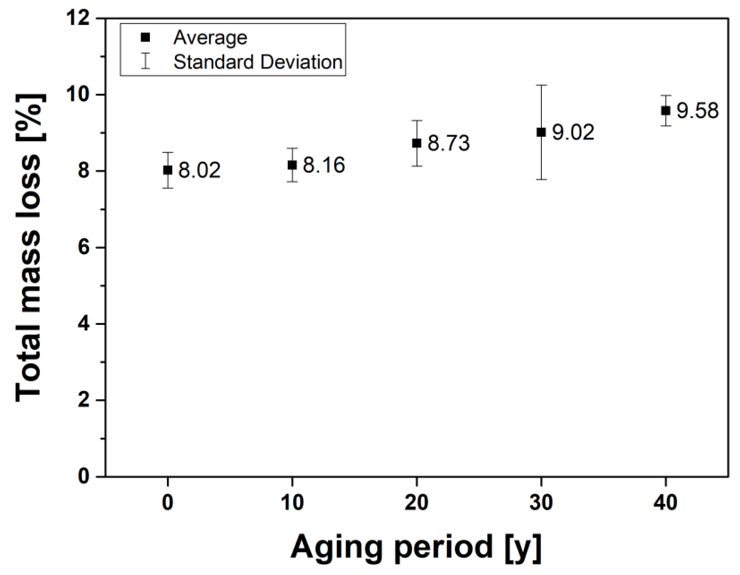
3.1. TG Analysis

Figure 3 shows TG and DTG (differential thermogravimetric) curves of the non-class 1E cable at heating rates of 5, 10, 15 and 20 °C/min. The initial temperature at which the thermal conversion reaction begins is approximately 250 °C. When the heating rate was increased from 5 to 20 °C/min, the peak temperature Tm shifted from 338.40 to 364.04 °C. A higher heating rate implies that the material reaches that temperature in a shorter time [25,33]. Hence, an increase in the heating rate tends to delay the thermal degradation process.
As shown in Figure 4, the TG analysis results were plotted in the ln(β/Tm2) versus 1/Tm domain to determine the slope of the linear fitting, which was identical to E/R. The correlation coefficient (R2) of the linear fitting was 0.9944, which indicated that ln(β/Tm2) and 1/Tm were highly correlated and proved the high reliability of the experimental results in compliance with Equation (2). From the obtained values of the slope of the line (=E/R), the intercept (=ln[αR/E]) and the Kissinger equation, the Ea of the non-class 1E cable was calculated as 163.20 kJ/mol (=1.691 eV), which was rather higher than the Ea of EPR cables in other studies (e.g., 1.23 eV was obtained by Kim et al. [34]; 0.98 eV was obtained by Park et al. [35]). In this study, a higher Ea was obtained because not only the EPR insulation but also the CR sheath were used in the TG analysis while the others did not. From the obtained Ea, the required accelerated aging time was calculated according to the aging period as shown in Table 3. The required time for aging increased linearly with an increased aging period but it varied significantly with respect to Ea and more time was required for it to be equally aged for the cable having a lower Ea. For example, 887 h, 1774 h, 2660 h and 3547 h were required for 10, 20, 30 and 40 year aging, respectively, when Ea = 1.23 eV; 2256 h, 4511 h, 6767 h and 9022 h were required for 10, 20, 30 and 40 year aging when Ea = 0.98 eV.

3.2. Combustion Characteristics in the Early Period

The fire performance index (FPI) and fire growth index (FGI) were observed as representative indicators of the combustion characteristics in the early period while HRR, THR and ML were analyzed as representative indicators of the combustion characteristics in the mid and late periods. As previously mentioned in Section 2.3, each test was replicated three times and both the average and the standard deviation (SD) of the test results were compared, as shown in Table 4. While the PHRR and the tPHRR had a small standard deviation relative to the mean value, the TTI had a large deviation up to 75.36% of the SD/mean. The large SD of 30 year and 40 year accelerated aged cables were attributed from the results that the TTI in only one test case was measured as more than 100 s. This phenomenon may be considered as a singular point but the irregular retards in the ignition was the nature of the fire itself so the data remained in the input of the calculation. The SDs of the PHRR and the tPHRR were under 15% so the repeatability of this study was within the acceptable level of significance when considering that the cone calorimeter test had a quite large deviation in most results up to several tens of percentage [36].
The FPI and FGI are defined as the ratio of the TTI to the PHRR and the ratio of the PHRR to the tPHRR, respectively. FPI and FGI can be obtained using Equations (3) and (4), respectively [37,38].
FPI = TTI PHRR ( s · m 2 / kW ) .
FGI = PHRR tPHRR ( kW / s · m 2 ) .
FPI and FGI are closely correlated with fire risk, as presented in Equation (5). A short TTI signifies the easy ignition of a fire; a high PHRR signifies serious damage due to the radiated heat during a fire; a short tPHRR signifies easy fire growth from the ignition to a fully developed fire during flashover.
FGI FPI Fire   risk .
As shown in Figure 5, the mean FPI of 30 and 40 year accelerated aged cables was larger than that of non-aged, 10 and 20 year accelerated aged cables. This result was very similar to those reported in NUREG/CR-2868 (Aging Effects on Fire Retardant Additives in Organic Materials for Nuclear Plant Applications) [39] and NUREG/CR-5619 (The Impact of Thermal Aging on the Flammability of Electric Cables) [40] published by the NRC. As both of them reported, the flame retardant performance of the aged cables was better than that of the non-aged cables because of the evaporated volatile components during the aging process of the cables consisting of EPR insulation and a chlorosulfonated polyethylene sheath. The results of this study also supported the fact that volatile components contained in the cable evaporated as the accelerated thermal aging progressed. In addition, the clue on the evaporation of volatile components with respect to aging could also be found by comparing the variations in the initial mass of specimens as shown in Table 4. The initial mass of same size specimens by volume base (=100 mm × 100 mm × 25 mm) decreased as the aging period increased and this fact was clear evidence of the loss of volatile components derived from thermal aging.
The sharp jump of the FPI on the 30 year accelerated aged cable should be noted. This sharp jump mainly resulted from the rapid increase in the TTI at 30 years. The reason for the large increase of the TTI at 30 years was that only one test case of 30 and 40 year accelerated aged cables ignited after 100 s from the start of the test. Hence, a large standard deviation was obtained for 30 and 40 year accelerated aged cables, as previously mentioned. These irregular results were considered not to be singular but the nondeterministic and irregular nature of fire itself. The ignition phenomenon has a high possibility of various irregularities as it involves complicated consecutive multi-processes of a thermal heating/pyrolysis/gasification/gas combustion reaction that should successfully and continuously be processed to be ignited. In addition, these results are stochastically meaningful when considering that the ignition in one of the three cases was delayed due to the evaporation of volatile organic compounds during the process of long thermal degradation. Thus, the increase in the FPI value was directly affected by the increase of the TTI and the decrease of the PHRR.
The FGI displayed a trend opposite to the FPI. The mean FGI of the 30 and 40 year accelerated aged cables were measured to be lower than the non-aged, 10 and 20 year accelerated aged cables. The mean tPHRR of the accelerated aged cables and the non-aged cable were measured at 80 s and 70 s, respectively. The FGI value decreased with a decreasing PHRR and an increasing tPHRR. Thus, it could be confirmed that the early fire risk decreased as the accelerated thermal aging progressed. However, Lee et al. [41] reported that the evaporation of the volatile components did not indicate a general trend to enhance the flame retardant performance. Therefore, in this study, the fire risk was evaluated in detail by analyzing the combustion characteristics of the mid to late period.

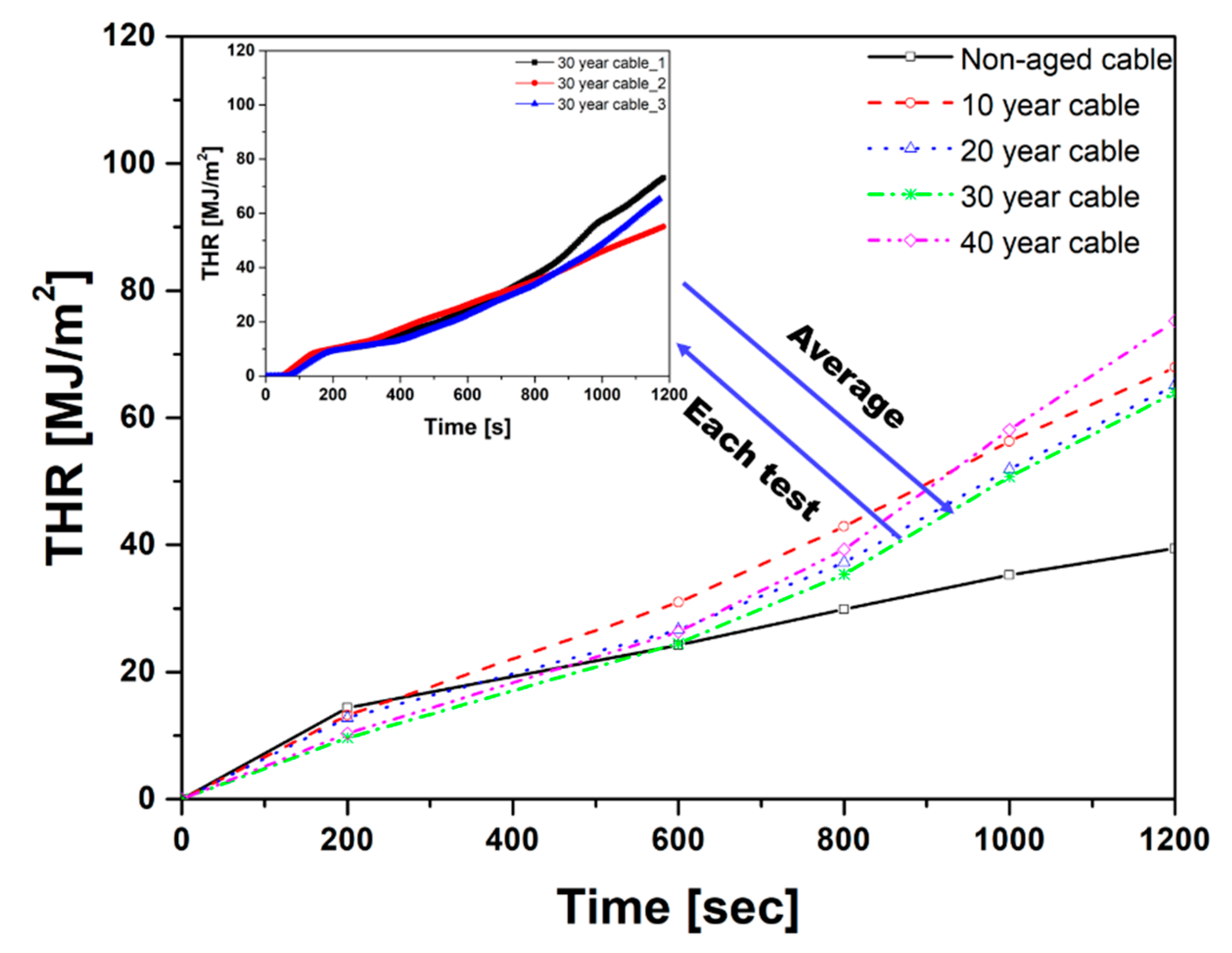
3.3. Combustion Characteristics in the Mid to Late Period

The combustion characteristics in the mid to late period were analyzed through the HRR, THR and ML and their results are shown in Figure 6, Figure 7 and Figure 8. Although the HRR, THR and ML included the combustion characteristics in the whole period of the test, we defined that they represented the combustion characteristics in the mid to late period because the PHRR and the tPHRR were already examined to characterize the combustion phenomenon in the early period in Section 3.2.
The results from the three repeated tests were averaged and plotted for each aging year and the results from each test run for the 30 year accelerated aged cable are provided in small plots in Figure 6 and Figure 7 to prove the qualitative repeatability of the time series test results. Other test cases had a similar level of repeatability to the 30 year accelerated aged cable and their plots are omitted for the readability and simplicity of the figures.
Figure 6 verifies the PHRR trend at 80 s as discussed in Section 3.2 followed by repeated instances of an increase and decrease in the HRR. The HRR characteristics in the late period (after 900 s) showed that the measured final peak value was larger than the initial peak value in the 30 and 40 year accelerated aged cables. This was due to the steady heat release from the split occurrence in the cable’s char layer because of continuous pyrolysis and combustion, which agreed with the results of Seo et al. [42]. Flame retardants are added to non-class 1E cables for NPPs to comply with a certain level of fire protection capability and they play a role in increasing the formation of the char layer and reinforcing cable strength [43]. In addition, Zhengzhou et al. [44] reported that the char layer formation delayed the pyrolysis by blocking heat penetration, which was also observed in the present study. The HRR curve of the non-aged cable was maintained at 25 kW/m2 after 80 s whereas that of the accelerated aged cables showed a tendency to increase continuously. It could be judged that as the accelerated thermal aging progressed beyond 10 years, the flame retardant performance deteriorated. This caused the unstable formation of the char layer, thereby generating constant pyrolysis and combustion. Thus, higher HRR values were displayed in the mid and late periods of combustion.
The mean THRs of the non-aged cables and the 10, 20, 30 and 40 year accelerated aged cables were calculated as 40 MJ/m2, 69 MJ/m2, 65 MJ/m2, 64 MJ/m2 and 77 MJ/m2, respectively, as shown in Figure 7. As the accelerated thermal aging progressed, the heat release increased due to a reduced flame retardant performance, a weakened bond between the molecules and the instability of the char layer. The increased heat release increased the fire risk in the accelerated aged cables as the initial fire transformed into the fully developed fire.
Figure 8 shows the ML of the non-aged cable and the accelerated aged cables during combustion. The ML is the rate of decrease for the initial mass over test time, as presented in Equation (6).
ML ( % ) =   m o m f m o × 100
where mo is the initial mass and mf is the final mass. The mean MLs of the non-aged cables and the 10, 20, 30 and 40 year accelerated aged cables were 8.02%, 8.16%, 8.73%, 9.01% and 9.58% and the SDs of the ML were 0.47, 0.44, 0.60, 1.24 and 0.40, respectively. The ratio of the SD to the mean ML was between 4.1% and 13.7% so it could be judged that the ML results had a reliable repeatability.
The unstable formation of the char layer can result in a steady heat release and pyrolysis. As a result, the reinforced combustion increased the mass loss rate in the accelerated aged cables, thereby leading to a larger ML. Not only the ML but also the change of absolute mass provided clear evidence of this assertion. The differences of mass before and after the combustion (=momf) were 54.40 g, 56.26 g, 58.60 g and 59.30 g for the 10, 20, 30 and 40 year accelerated aged cables, respectively, so the increase of mass reduction could be considered as the results affected the more rigorous combustion reaction of the more aged cables.

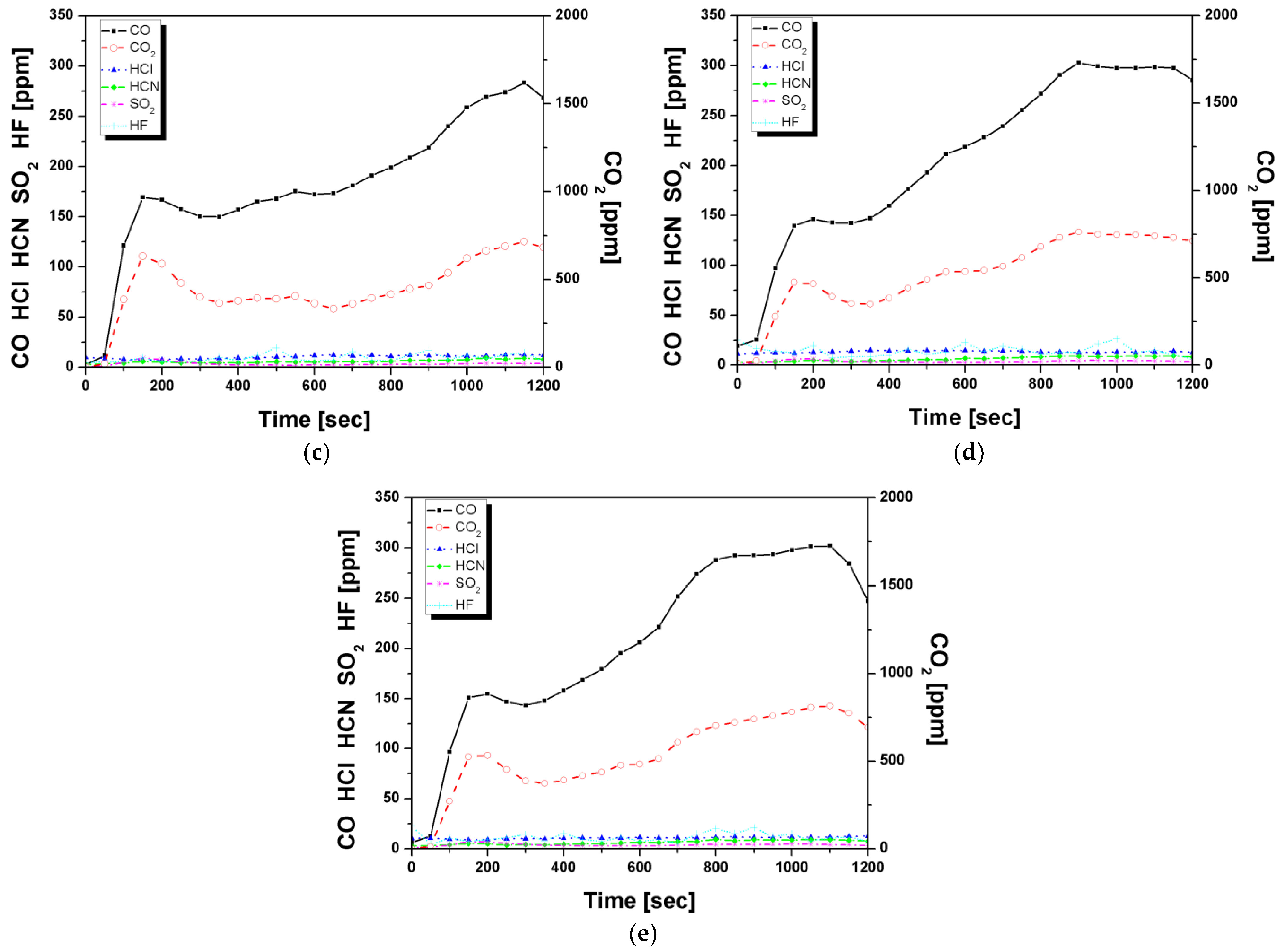
3.4. Emission Characteristics of Toxic Gases

The emission characteristics of CO, CO2, HCN, HCl, HBr, HF, SO2 and NOX during combustion were examined according to the ISO 19702 standards. The results presented in Figure 9 show that CO, CO2, HCN and HCl were commonly detected for all test cases whereas HBr and NOx were not detected for all test cases. HF and SO2 were released from the accelerated aged cables.
For the non-aged and accelerated aged cables, the CO2 curves exhibited the first peak at 150 s. These peak values showed a decreasing tendency as the accelerated thermal aging progressed. The CO2 peak value of the non-aged cable was measured to be higher than that of the accelerated aged cables. It could be seen that a large amount of CO2 gas was released as the volatile components present in the cables were burned. However, the CO2 peak decreased with accelerated thermal aging because volatile components evaporated during the accelerated thermal aging. CO2 released by the non-aged cables decreased significantly and remained at approximately 500 ppm after 350 s. In contrast, the accelerated aged cables increased to approximately 750 ppm after 350 s. It could be seen that the unstable char layer in the accelerated aged cables led to heat penetration and continuous combustion.
The similar emission trends of CO with CO2 could be clearly seen for all cases (Figure 9), which signified that both CO and CO2 were released concurrently as combustion progressed. These two emission gases are major components of product gas and affect the toxicity in the largest portion. The CO released by the non-aged cables showed a peak value of approximately 150 ppm at 150 s and was maintained at approximately 100 ppm. However, CO released by the accelerated aged cables was approximately 250–300 ppm after 150 s. CO gas could be formed due to the oxidation of char [28] and the aforementioned unstable char layer could promote the oxidation of the char layer as the accelerated aging progressed. It is notable that the whole emissions of CO and CO2 during the combustion time until 1200 s increased with the aging period while the initial emission of CO and CO2 during the combustion time until 200 s decreased as the aging period increased. These results coincided with the results obtained from the HRR and the THR, which had similar time series trends with these emission data because both the release and emission gases were products of the combustion reaction and indicated how much the cables were well burnt.
The maximum HCl release of the non-aged cable, 10 year accelerated aged cable and beyond 20 year accelerated aged cables were 250 ppm, 100 ppm and 15 ppm, respectively. As can be seen from Figure 10, the HCl values decreased significantly with aging. HCl release during combustion is mainly due to the Cl content [45]. In this study, the HCl gas was mainly released from the sheath of the non-class 1E cable consisting of the CR. For polymers containing Cl, dehydrochlorination can occur during the thermal degradation process [46,47,48]. Therefore, the decrease in the HCl released by the beyond 20 year accelerated aged cables could be attributed to dehydrochlorination that occurred with thermal aging.
The HCN released by the non-aged and accelerated aged cables were approximately 2 ppm and 6 ppm, respectively. HCN gas can be produced during heating under air conditions at 700–1000 °C and the amount of HCN increases with an increasing temperature [49]. As the cone calorimeter test is conducted in an open system, air can be supplied during combustion [42]. Therefore, it seemed that the HCN concentration of the accelerated aged cables was measured to be higher than the non-aged cable because the HRR of the accelerated aged cable increased compared with that of the non-aged cable maintained after 80 s.
HF and SO2 were only released from the accelerated aged cables. Although the composition of the cables is confidential and was not provided by the cable supplier, it could be estimated that these two gases might be attributed from the additives in the cables. A flame retardant consisting of F added chemical composites might be applied to increase the thermal and photochemical safety and durability and a small amount of S might be added to the cable sheath and insulation to maintain excellent heat resistance [50,51,52]. The SO2 released by all cables was approximately 3–5 ppm and the release of HF was around 10–30 ppm. It was notable that neither HF nor SO2 was detected in the case of the non-aged cable. Three repeated tests for the non-aged cable showed the same results that no HF and SO2 were detected whereas all of the tests for the aged cables detected a small amount of HF and SO2. From these results, it was difficult to determine whether S or F was contained the cable so an SEM-EDS analysis was performed to find clear evidence of the elements in the cable in Section 3.5.

3.5. SEM-EDS Analysis

The SEM equipment was used to analyze changes in the surface structure of the sheath and insulation with accelerated aging. An EDS microanalysis was conducted to obtain information on the elemental composition of the sheath and insulation. Figure 10 shows the SEM images of the insulation with accelerated aging. In the aged cables, voids and cracks were observed, as shown by the dotted yellow circles in Figure 10b,c. These small voids and cracks could be newly formed and expanded through the accelerated thermal aging, which was also observed in [53]. The voids and cracks significantly degraded the flame retardant performance of the cables by allowing oxygen penetration into the cable sheath.
Figure 11 and Figure 12 show the SEM image matrix, as demonstrated by EDS elemental mapping of the sheath and insulation. As seen in Figure 11 and Figure 12, the flame retardant components were identified to include the halogenated elements F and Cl and the additive of S, which matched well with the FTIR results in Section 3.4. The chemical elements were homogeneously distributed on the surface and also supported the reliability of the experiments and materials in this study. Other cases of non-aged and aged cables showed similar results, which included carbon, chlorine, sulfur, oxygen and fluorine so it could be confirmed that these elements were contained in the non-class 1E cable.

4. Conclusions

In this study, the combustion characteristics of a non-class 1E cable were investigated according to the ISO 5660-1 and ISO 19702 standards. The effect of accelerated thermal aging on the combustion characteristics was investigated and the following conclusions were obtained.
The FPI and FGI were analyzed to determine the early combustion characteristics. As the aging period increased, the FPI increased while the FGI tended to decrease. This was because the evaporation of volatile components during the thermal aging process reduced the initial ignition possibility thereby delaying the ignition time and reducing the initial PHRR value.
The HRR, THR and ML over time were analyzed to examine the mid to late combustion characteristics. Larger values of HRR, THR and MLR were observed for the accelerated aged cables than the non-aged cables because of continuous pyrolysis and heat release, which was affected by the unstable formation of the char layer.
For the emission characteristics of harmful combustion gases, as the aging period increased, the values of the three gases (CO2, CO and HCl) were notable. The peak of the CO2 emission significantly decreased in the accelerated aged cables when compared with the non-aged cable because the volatile components evaporated during the accelerated thermal aging process. In the late period of fire, after 350 s from the ignition, the CO2 emission in the accelerated aged cables increased due to a continuous combustion derived from the unstable char layer. HCl tended to significantly decrease as the aging progressed beyond 10 years due to dehydrochlorination resulting from the accelerated aging process.
To evaluate the overall fire risks from the test results, the combustion characteristics of each cable due to aging revealed that the fire risk was lower at the early combustion characteristics owing to the low ignition possibility. In contrast, the fire risk increased in the mid and late periods due to continuous pyrolysis and heat release. In addition, the gases released during combustion showed various changes with the aging periods.
The results and test data from this study can be used for qualitative assessment of fire risks in NPPs. The reinforcement of appropriate regulatory guides should reflect the increased toxicity and high risks in mid to late period fires.
The results of this study can be practically used when setting up reinforced safety codes and standards of cables used for NPPs especially in consideration with the flame retardant performance with respect to the aging period. In addition, operators of NPPs can refer to the results of this study when developing a manual or standard operation procedure (SOP) in emergency situations. For instance, as they cannot evacuate from the control room during the operation of NPPs even in the case of a fire the information on the toxicity and combustion characteristics from the cables should be carefully considered when planning a proper operation procedure ensuring both the safety of operators and the normal operation of NPPs.

Author Contributions

Conceptualization, M.C.L. and S.K.L.; data curation, M.H.K. and H.J.S.; formal analysis, M.H.K. and M.C.L.; funding acquisition, S.K.L.; investigation, M.H.K.; methodology, M.H.K., H.J.S., S.K.L. and M.C.L.; validation, M.H.K. and M.C.L.; writing—original draft, M.H.K.; writing—review and editing, M.C.L. and S.K.L. All authors have read and agreed to the published version of the manuscript.

Funding

This work was supported by the Nuclear Safety Research Program through the Korea Foundation of Nuclear Safety (KOFONS) using the financial resource granted by the Nuclear Safety and Security Commission (NSSC) of the Republic of Korea (No. 1705002).

Conflicts of Interest

The authors declare no conflict of interest.

References

  1. Chi, X.; Li, J.; Ji, M.; Liu, W.; Li, S. Thermal-oxidative aging effects on the dielectric properties of nuclear cable insulation. Materials 2020, 13, 2215. [Google Scholar] [CrossRef]
  2. Gillen, K.T.; Bernstein, R. Review of Nuclear Power Plant Safety Cable Aging Studies with Recommendations for Improved Approaches and for Future Work; Sandia Report; SAND 2010-7266; Sandia National Laboratories: Albuquerque, NM, USA, 2010. [Google Scholar]
  3. Meinier, R.; Sonnier, R.; Zavaleta, P.; Suard, S.; Ferry, L. Fire behavior of halogen-free flame retardant electrical cables with the cone calorimeter. J. Hazard. Mater. 2018, 342, 306–316. [Google Scholar] [CrossRef]
  4. Verardi, L.; Fabiani, D.; Montanari, G.C. Electrical aging markers for EPR-based low-voltage cable insulation wiring of nuclear power plants. Radiat. Phys. Chem. 2014, 94, 166–170. [Google Scholar] [CrossRef]
  5. Santhosh, T.V.; Gopika, V.; Ghosh, A.K.; Fernandes, B.G. An approach for reliability prediction of instrumentation & control cables by artificial neural networks and Weibull theory for probabilistic safety assessment of NPPs. Reliab. Eng. Syst. Saf. 2018, 170, 31–44. [Google Scholar] [CrossRef]
  6. Hashemian, H.M.; McConkey, B.; Harmon, G.; Sexton, C. Methods for testing nuclear power plant cables. IEEE Instrum. Meas. Mag. 2013, 16, 31–36. [Google Scholar] [CrossRef]
  7. Bouguedad, D.; Mekhaldi, A.; Jbara, O.; Rondot, S.; Hadjadj, A.; Douglade, J.; Dony, P. Physico-chemical study of thermally aged EPDM used in power cables insulation. IEEE Trans. Dielectr. Electr. Insul. 2015, 22, 3207–3215. [Google Scholar] [CrossRef]
  8. Boukezzi, L.; Rondot, S.; Jbara, O.; Boubakeur, A. Study of thermal aging effects on the conduction and trapping of charges in XLPE cable insulations under electron beam irradiation. Radiat. Phys. Chem. 2018, 149, 110–117. [Google Scholar] [CrossRef]
  9. Bowler, N.; Liu, S. Aging mechanisms and monitoring of cable polymers. Int. J. Progn. Heal. Manag. 2015, 6. [Google Scholar] [CrossRef]
  10. Pfaendner, R. (Photo)oxidative degradation and stabilization of flame retarded polymers. Polym. Degrad. Stab. 2013, 98, 2430–2435. [Google Scholar] [CrossRef]
  11. Zhang, Y.; Hou, Z.; Wu, K.; Wang, S.; Li, J.; Li, S. Influence of Oxygen Diffusion on Thermal Ageing of Cross-Linked Polyethylene Cable Insulation. Materials 2020, 13, 2056. [Google Scholar] [CrossRef]
  12. Šarac, T.; Quiévy, N.; Gusarov, A.; Konstantinović, M.J. Influence of γ-irradiation and temperature on the mechanical properties of EPDM cable insulation. Radiat. Phys. Chem. 2016, 125, 151–155. [Google Scholar] [CrossRef]
  13. Min, D.; Yan, C.; Huang, Y.; Li, S.; Ohki, Y. Dielectric and carrier transport properties of silicone rubber degraded by gamma irradiation. Polymers 2017, 9, 533. [Google Scholar] [CrossRef] [PubMed]
  14. Zhu, W.; Zhao, Y.; Han, Z.; Wang, X.; Wang, Y. Thermal Effect of Different Laying Modes on Cross-Linked Polyethylene (XLPE) Insulation and a New Estimation on Cable Ampacity. Energies 2019, 12, 2994. [Google Scholar] [CrossRef] [Green Version]
  15. Kang, S.D.; Kim, J.H. Investigation on the insulation resistance characteristics of low voltage cable. Energies 2020, 13, 3611. [Google Scholar] [CrossRef]
  16. Zhang, B.S.; Zhang, J.Q.; Li, Q.; Wang, L.F.; Xie, H.; Fan, M.H. Effects of Insulating Material Ageing on Ignition Time and Heat Release Rate of the Flame Retardant Cables. Procedia Eng. 2018, 211, 972–978. [Google Scholar] [CrossRef]
  17. IEEE Std. 383-1974. IEEE Standard for Type Test of Class 1E Electric Cables, Field Splices, and Connections for Nuclear Power Generating Stations; IEEE: New York, NY, USA, 1974.
  18. IEEE Std. 1202-1991. IEEE Standard for Flame Testing of Cable Tray in Industrial and Commercial Occupancies; IEEE: New York, NY, USA, 1991.
  19. NUREG-0800. Standard Review Plan for the Review of Safety Analysis Reports for Nuclear Power Plants: LWR Edition; Nuclear Regulatory Commission (NRC): Rockville, MD, USA, 1987.
  20. Jiang, Z.; Liu, Z.; Fei, B.; Cai, Z.; Yu, Y.; Liu, X. The pyrolysis characteristics of moso bamboo. J. Anal. Appl. Pyrolysis 2012, 94, 48–52. [Google Scholar] [CrossRef]
  21. Farag, S.; Chaouki, J. A modified microwave thermo-gravimetric-analyzer for kinetic purposes. Appl. Therm. Eng. 2015, 75, 65–72. [Google Scholar] [CrossRef]
  22. Seo, H.J.; Kim, N.K.; Lee, M.C.; Lee, S.K.; Moon, Y.S. Investigation into the toxicity of combustion products for CR/EPR cables based on aging period. J. Mech. Sci. Technol. 2020, 34, 1785–1794. [Google Scholar] [CrossRef]
  23. Xu, L.; Li, S.; Sun, W.; Ma, X.; Cao, S. Combustion behaviors and characteristic parameters determination of sassafras wood under different heating conditions. Energy 2020, 203. [Google Scholar] [CrossRef]
  24. Blaine, R.L.; Kissinger, H.E. Homer Kissinger and the Kissinger equation. Thermochim. Acta 2012, 540, 1–6. [Google Scholar] [CrossRef]
  25. Apaydin-Varol, E.; Polat, S.; Putun, A.E. Pyrolysis kinetics and thermal decomposition behavior of polycarbonate—A TGA-FTIR study. Therm. Sci. 2014, 18, 833–842. [Google Scholar] [CrossRef]
  26. ISO 5660-1. Reaction to Fire tests—Heat release, Smoke Production and Mass Loss Rate—Part 1: Heat Release Rate (Cone Calorimeter Method) and Smoke Production Rate (Dynamic Measurement); ISO: Geneva, Switzerland, 2015.
  27. ISO 19702. Guidance for Sampling and Analysis of Toxic Gases and Vapours in Fire Effluents Using Fourier Transform Infrared (FTIR) Spectroscopy; ISO: Geneva, Switzerland, 2015.
  28. Fateh, T.; Rogaume, T.; Luche, J.; Richard, F.; Jabouille, F. Characterization of the thermal decomposition of two kinds of plywood with a cone calorimeter—FTIR apparatus. J. Anal. Appl. Pyrolysis 2014, 107, 87–100. [Google Scholar] [CrossRef]
  29. Puente, E.; Lázaro, D.; Alvear, D. Study of tunnel pavements behaviour in fire by using coupled cone calorimeter—FTIR analysis. Fire Saf. J. 2016, 81, 1–7. [Google Scholar] [CrossRef]
  30. Luche, J.; Rogaume, T.; Richard, F.; Guillaume, E. Characterization of thermal properties and analysis of combustion behavior of PMMA in a cone calorimeter. Fire Saf. J. 2011, 46, 451–461. [Google Scholar] [CrossRef]
  31. Kutchko, B.G.; Kim, A.G. Fly ash characterization by SEM-EDS. Fuel 2006, 85, 2537–2544. [Google Scholar] [CrossRef]
  32. Genestar, C.; Pons, C. Earth pigments in painting: Characterisation and differentiation by means of FTIR spectroscopy and SEM-EDS microanalysis. Anal. Bioanal. Chem. 2005, 382, 269–274. [Google Scholar] [CrossRef] [PubMed]
  33. Damartzis, T.; Vamvuka, D.; Sfakiotakis, S.; Zabaniotou, A. Thermal degradation studies and kinetic modeling of cardoon (Cynara cardunculus) pyrolysis using thermogravimetric analysis (TGA). Bioresour. Technol. 2011, 102, 6230–6238. [Google Scholar] [CrossRef]
  34. Kim, J.Y.; Park, D.H. Thermal analysis and statistical evaluation of EPR used in nuclear power plants. In Proceedings of the 2015 IEEE Electrical Insulation Conference (EIC), Seattle, WA, USA, 7–10 June 2015; pp. 5–8. [Google Scholar] [CrossRef]
  35. Kim, J.; Yang, J.; Lee, G.; Seong, B.; Bang, J.; Park, D. Mechanical Properties and Statistical Evaluation of EPR According to the Accelerated Degradation. J. Korean Inst. Electr. Electron. Mater. Eng. 2015, 28, 501–507. [Google Scholar] [CrossRef] [Green Version]
  36. Marquis, D.; Guillaume, E.; Lesenechal, D. Accuracy (trueness and precision) of cone calorimeter tests with and without a vitiated air enclosure. Procedia Eng. 2013, 62, 103–119. [Google Scholar] [CrossRef] [Green Version]
  37. Jiao, C.; Chen, X.; Zhang, J. Synergistic effects of Fe2O3 with layered double hydroxides in EVA/LDH composites. J. Fire Sci. 2009, 27, 465–479. [Google Scholar] [CrossRef]
  38. Wang, B.; Tang, Q.; Hong, N.; Song, L.; Wang, L.; Shi, Y.; Hu, Y. Effect of cellulose acetate butyrate microencapsulated ammonium polyphosphate on the flame retardancy, mechanical, electrical, and thermal properties of intumescent flame-retardant ethylene-vinyl acetate copolymer/microencapsulated ammonium polyphosphate/. ACS Appl. Mater. Interfaces 2011, 3, 3754–3761. [Google Scholar] [CrossRef] [PubMed]
  39. Clough, R.L. Aging Effects on Fire-Retardant Additives in Organic Materials for Nuclear Plant Applications. In NUREG/CR-2868 SAND82-0485; Nuclear Regulatory Commission (NRC): Rockville, MD, USA, 1982. [Google Scholar]
  40. Nowlen, S.P. An Investigation of the Effects of Thermal Aging on, the Fire Damageability of Electric Cables. In NUREG/CR-5619 SAND90-2121; Nuclear Regulatory Commission (NRC): Rockville, MD, USA, 1991. [Google Scholar]
  41. Lee, S.K.; Moon, Y.S.; Yoo, S.Y. A Study on Validation Methodology of Fire Retardant Performance for Cables in Nuclear Power Plants. J. Korean Soc. Saf. 2017, 32, 140–144. [Google Scholar] [CrossRef]
  42. Seo, H.J.; Kim, N.K.; Lee, M.C.; Lee, S.K.; Moon, Y.S. An Experimental Study on the Combustion Characteristics of Non Class 1E Cables. J. Korean Soc. Combust. 2019, 24, 15–24. [Google Scholar] [CrossRef]
  43. Gallina, G.; Bravin, E.; Badalucco, C.; Audisio, G.; Armanini, M.; De Chirico, A.; Provasoli, F. Application of cone calorimeter for the assessment of class of flame retardants for polypropylene. Fire Mater. 1998, 22, 15–18. [Google Scholar] [CrossRef]
  44. Wang, Z.; Shen, X.; Fan, W.; Hu, Y.; Qu, B.; Gui, Z. Effects of poly(ethylene-co-propylene) elastomer on mechanical properties and combustion behaviour of flame retarded polyethylene/magnesium hydroxide composites. Polym. Int. 2002, 51, 653–657. [Google Scholar] [CrossRef]
  45. Wang, C.; Wu, Y.; Liu, Q.; Yang, H.; Wang, F. Analysis of the behaviour of pollutant gas emissions during wheat straw/coal cofiring by TG-FTIR. Fuel Process. Technol. 2011, 92, 1037–1041. [Google Scholar] [CrossRef]
  46. Beneš, M.; Milanov, N.; Matuschek, G.; Kettrup, A.; Plaček, V.; Balek, V. Thermal degradation of PVC cable insulation studied by simultaneous TG-FTIR and TG-EGA methods. J. Therm. Anal. Calorim. 2004, 78, 621–630. [Google Scholar] [CrossRef]
  47. Zhu, H.M.; Jiang, X.G.; Yan, J.H.; Chi, Y.; Cen, K.F. TG-FTIR analysis of PVC thermal degradation and HCl removal. J. Anal. Appl. Pyrolysis 2008, 82, 1–9. [Google Scholar] [CrossRef]
  48. Subramaniam, K.; Das, A.; Häußler, L.; Harnisch, C.; Stöckelhuber, K.W.; Heinrich, G. Enhanced thermal stability of polychloroprene rubber composites with ionic liquid modified MWCNTs. Polym. Degrad. Stab. 2012, 97, 776–785. [Google Scholar] [CrossRef]
  49. Wang, B.; Sheng, H.; Shi, Y.; Song, L.; Zhang, Y.; Hu, Y.; Hu, W. The influence of zinc hydroxystannate on reducing toxic gases (CO, NOx and HCN) generation and fire hazards of thermoplastic polyurethane composites. J. Hazard. Mater. 2016, 314, 260–269. [Google Scholar] [CrossRef]
  50. Chen, S.I.; Sheu, Y.L.; Sheu, J.L.; Lee, C.T.; Lin, J.S. Morphology of perfluoroalkylacrylate/stearyl methacrylate polymers and their effect on water/oil repellency. J. Appl. Polym. Sci. 1997, 63, 903–909. [Google Scholar] [CrossRef]
  51. Errifai, I.; Jama, C.; Le Bras, M.; Delobel, R.; Gengembre, L.; Mazzah, A.; De Jaeger, R. Elaboration of a fire retardant coating for polyamide-6 using cold plasma polymerization of a fluorinated acrylate. Surf. Coatings Technol. 2004, 180–181, 297–301. [Google Scholar] [CrossRef]
  52. Iezzi, R.A.; Gaboury, S.; Wood, K. Acrylic-fluoropolymer mixtures and their use in coatings.pdf. Prog. Org. Coat. 2000, 40, 55–60. [Google Scholar] [CrossRef]
  53. Hsu, Y.T.; Chang-Liao, K.S.; Wang, T.K.; Kuo, C.T. Monitoring the moisture-related degradation of ethylene propylene rubber cable by electrical and SEM methods. Polym. Degrad. Stab. 2006, 91, 2357–2364. [Google Scholar] [CrossRef]
Figure 1. Cross-sectional view of a non-class 1E cable.
Energies 14 02003 g001
Figure 2. Schematic and specimen of a cone calorimeter FTIR (Fourier Transform Infrared Spectroscopy) test.
Energies 14 02003 g002
Figure 3. Thermogravimetric (TG) and differential thermogravimetric (DTG) curves of the non-class 1E cable at different heating rates.
Energies 14 02003 g003
Figure 4. Kissinger plot of the non-class 1E cable.
Energies 14 02003 g004
Figure 5. Fire performance index (FPI) and fire growth index (FGI) with respect to the accelerated aging periods.
Energies 14 02003 g005
Figure 6. Time series heat release rate (HRR) with respect to the accelerated aging periods.
Energies 14 02003 g006
Figure 7. Time series total heat release (THR) with respect to the accelerated aging periods.
Energies 14 02003 g007
Figure 8. Total mass loss with respect to the accelerated aging periods.
Energies 14 02003 g008
Figure 9. Time series combustion gas emissions of (a) non-aged cable; (b) 10 year accelerated aged cable; (c) 20 year accelerated aged cable; (d) 30 year accelerated aged cable; (e) 40 year accelerated aged cable.
Energies 14 02003 g009aEnergies 14 02003 g009b
Figure 10. A void and a crack in the SEM image for the insulation of (a) non-aged cable; (b) 30 year accelerated aged cable; (c) 40 year accelerated aged cable.
Energies 14 02003 g010
Figure 11. SEM-EDS investigation on the sheath of a 40 year accelerated aged cable at (a) 500× magnification and (b) its elemental mapping.
Energies 14 02003 g011
Figure 12. SEM-EDS investigation on the insulation of a 40 year accelerated aged cable at (a) 500× magnification and (b) its elemental mapping.
Energies 14 02003 g012
Table 1. Specification of experimental cable.
DivisionDetail
ApplicationPower/Control
Voltage [V]600
Outer diameter [mm]25
Material propertiesSheathPolychloroprene rubber (CR)
InsulationEthylene propylene rubber (EPR)
ConductorCopper
Table 2. Cone calorimeter test conditions.
Test ConditionValue
Size of specimens (mm3)100 × 100 × 25
The number of tests for each cable3
Test running time (min)20
Heat flux (kW/m2)50
Exhaust flow (m3/s)0.024 ± 0.002
Table 3. Required time for accelerated aging calculated by the Arrhenius equation.
Aging Period [y]Required Time [h]
Ea = 1.69 eV
(The Present Study)
Ea = 1.23 eV
(Ref. [34])
Ea = 1.69 eV
(The Present Study)
101578872256
2031517744511
3047226606767
4063035479022
Table 4. Mean and standard deviation for each of the test values.
ParameterNumber of Repeated TestsAging Period [y]MeanSDSD/Mean (%)
PHRR [kW/m2]3Non-aged146.193.082.11%
10131.142.321.77%
20125.231.771.41%
3092.053.704.02%
4099.321.961.97%
TTI [s]3Non-aged380.581.52%
104412.6628.77%
20313.4611.16%
307349.1067.26%
405642.2075.36%
tPHRR [s]3Non-aged722.653.68%
10884.935.60%
20803.794.74%
308811.9313.56%
40839.5011.45%
FPI [s-m2/kW]3Non-aged0.2620.0051.88%
100.3330.09428.26%
200.2480.02710.73%
300.7890.50564.01%
400.5600.39670.71%
FGI [kW/m2-s]3Non-aged2.0300.0964.71%
101.4900.0734.92%
201.5650.0372.33%
301.0460.24423.33%
401.1970.1139.42%
Initial mass [g]3Non-aged71910.151.41%
106672.940.44%
206456.310.98%
306505.110.79%
406197.631.23%
Publisher’s Note: MDPI stays neutral with regard to jurisdictional claims in published maps and institutional affiliations.

