Article

Tower Configuration Impacts on the Thermal and Flow Performance of Steel-Truss Natural Draft Dry Cooling System

1
Key Laboratory of Power Station Energy Transfer Conversion and System of Ministry of Education, School of Energy Power and Mechanical Engineering, North China Electric Power University, Beijing 102206, China
2
North China Electric Power Research Institute Co. Ltd., Beijing 100045, China
*
Author to whom correspondence should be addressed.
Energies 2021, 14(7), 2002; https://doi.org/10.3390/en14072002
Submission received: 14 March 2021 / Revised: 24 March 2021 / Accepted: 25 March 2021 / Published: 5 April 2021

Abstract

:
In recent years, the steel-truss natural draft dry cooling technique has received attention owing to its advantages in better aseismic capability, shorter construction period, and preferable recycling. For cooling towers generating the draft force of air flow, its configuration may impact the thermal and flow performance of the steel-truss natural draft dry cooling system. With regard to the issue, this work explored the thermal and flow characteristics for the steel-truss natural draft dry cooling systems with four typical engineering tower configurations. By numerical simulation, the pressure, flow, and temperature contours were analyzed, then air mass flow rates and heat rejections were calculated and compared for the local air-cooled sectors and overall steel-truss natural draft dry cooling systems with those four tower configurations. The results present that tower 2 with the conical/cylindrical configuration had slightly lower heat rejection compared with tower 1 with the traditional hyperbolic configuration. Tower 3 with the hyperbolic/cylindrical configuration showed better thermo-flow performances than tower 1 at high crosswinds, while tower 4 with the completely cylindrical configuration appeared to have much reduced cooling capability under various crosswind conditions, along with strongly deteriorated thermal and flow behaviors. As for engineering application of the steel-truss natural draft dry cooling system, the traditional hyperbolic tower configuration is recommended for local regions with gentle wind, while for those areas with gale wind yearly, the hyperbolic/cylindrical integrated cooling tower is preferred.

1. Introduction

In some thermal, nuclear, and solar power stations, dry-cooling systems with natural ventilation (NDDCS) have obtained extensive application because of their prominent water-saving superiority [1,2]. As the cooling system technology develops, NDDCS with the steel-truss cooling tower has been the concern of the industrial and academic fields. Compared with cooling systems with concrete towers, the steel-truss NDDCS shows better aseismic capability, shorter construction period, and preferable recycling [3]; however, its cooling performance with various typical tower configurations in engineering has not yet been revealed. Given this situation, this research will disclose the thermo-flow characteristics of the steel-truss NDDCSs with four common practical tower configurations (more details in Section 2.1), which may provide some theoretical suggestions for the thermal design of steel-truss natural draft dry cooling systems.
In recent years, research has mainly focused on exploring stability performances, connection systems, wind induced dynamic impacts, and static behaviors of the steel-truss NDDCS. Ma et al. [4] studied seven latticed tower shell systems with various grid forms, finding that the optimized construction differs for steel-truss cooling systems with different tower heights. Geometric parameters, such as the connector type, bolt row number, and thickness of plate, were investigated, and then the proposed beam-column connections were proved with improved bending rigidity as well as ultimate bending performance [5]. On the basis of the extremely large hyperbolic steel-truss cooling system with the height of 216.3 m, which incorporates the double layers for the tower configuration, the dynamic performances were deeply revealing, pointing out that cooling towers with this steel-structure have higher natural vibration frequencies, smaller variance ratio, weaker sensitivity of dynamic response, and simpler resonant modes [6]. The stiffening rings near the tower throat and tower outlet of single-layer hyperbolic steel-truss natural draft dry cooling systems are shown to be quite necessary for enhancing the structural rigidity and stability [7].
The studies mentioned above paid close attention to handling structural design issues; however, investigations on the thermal design of steel-truss NDDCS remain scarce. Recently, a steel tower with the cylinder/frustum configuration was proposed and taken as the study object of the experiment and numerical simulation. For this steel-tower configuration, a geometric parameter of the proportion of the frustum section height to the entire tower height was recommended with a range from 0.3 to 0.5 [8]. This research can actually provide some guidelines for the cooling performance design of the steel-truss NDDCS; however, it is worth pointing out that a systematic study on clarifying thermal and flow behaviors of steel-truss natural draft dry cooling systems with various engineering tower configurations is quite necessary to promote thermal design to a further extent.
As also illustrated, most investigations of the thermo-flow performances concentrate on the concrete NDDCS with the hyperbolic tower configuration. Zhao et al. [9,10] presented specific thermal coupling of the flow contours for local cooling deltas at ambient conditions of 0 m/s, 4 m/s, and 12 m/s. Under wind speeds smaller than the critical value, Ma et al. [11] put forward a useful theoretical method to describe the heat transfer performances of NDDCS. The ambient air reverse flow near the outlet of tower will decrease the cooling capability of the cooling system [12]. Corresponding measures to improve the thermo-flow performance include water flow redistribution of the air-cooled sectors [13,14,15], installing windbreaker walls [16,17,18,19,20,21,22,23], and also air precooling [24,25,26]. Heat transfer processes for the transient start-up of cooling systems have been clearly disclosed [27,28,29]. Additionally, under cold ambient temperatures, the anti-freezing coupling of the thermal process of hot water and frigid air was fully studied [30,31,32,33,34,35]. The impact of the outdoor air fraction by economizer control type in cooling system loads based on real air handling unit operation parameters was disclosed, which provided references for economizer controls at hot-humid conditions [36]. Temperature fields and thermal stresses of aircraft key components of a simple geometric shape have also been studied by numerical modelling [37]. Furthermore, a mathematical model was proposed to solve convective heat transfer on the surface of typical structural elements of modern perspective aircrafts [38]. Thermo-flow investigations of these industrial units could provide some modelling references.
In conclusion, this research will carry out a thorough investigation on the thermal and flow performance of steel-truss NDDCSs with four typical engineering tower configurations, which are the traditional hyperbolic, conical/cylindrical, hyperbolic/cylindrical, and cylindrical cooling towers. With the numerical modelling method, air variable fields of various tower configurations were first analyzed, and then the mass flow rates, as well as heat rejections for local air-cooled heat exchangers (ACHE), were presented. Finally, the overall thermal and flow dimensionless parameters for all typical steel-truss cooling towers were compared. By analyzing the results, this work may offer some theoretical support for thermal design of the steel-truss NDDCS by filling the corresponding gap.

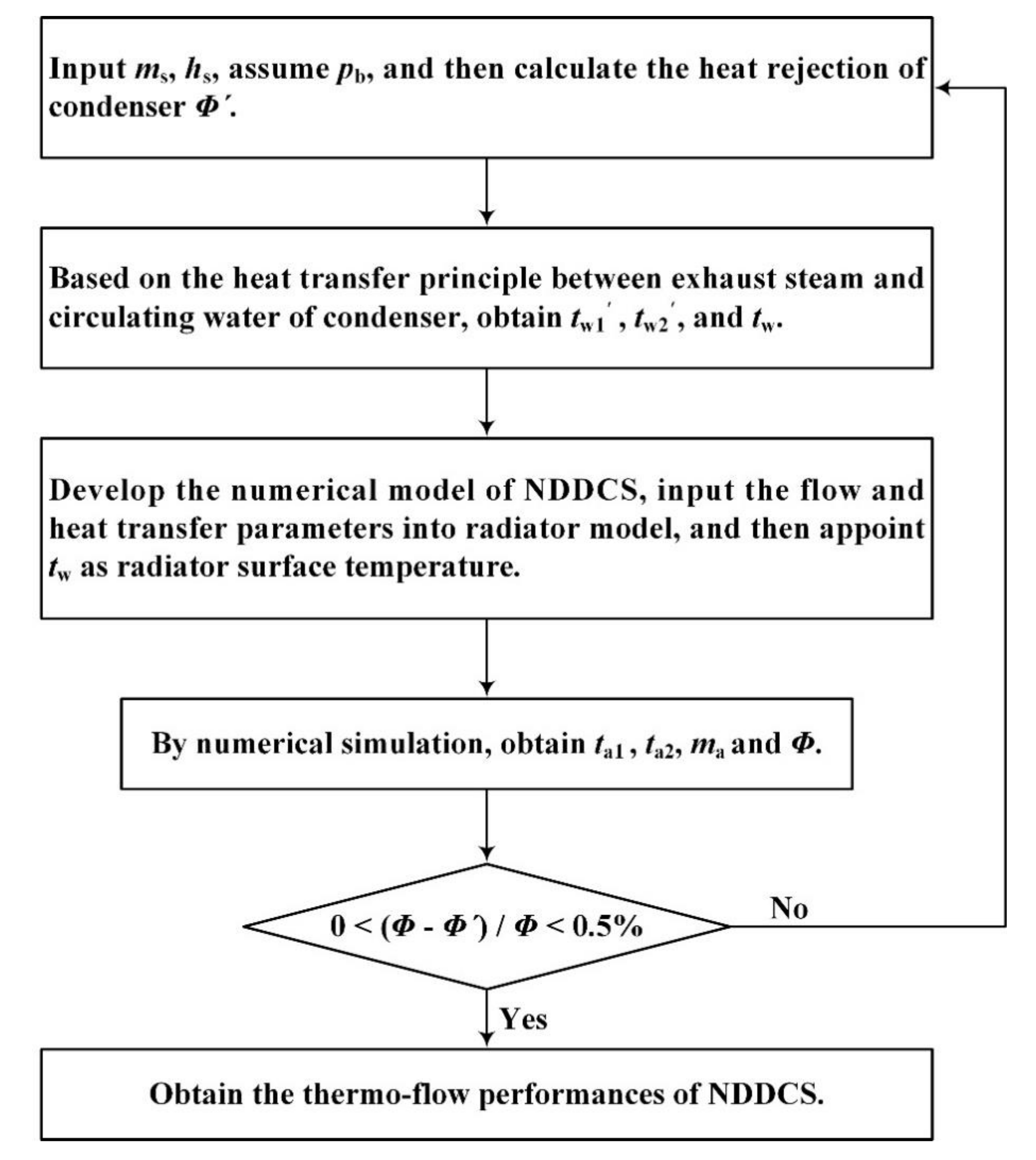
2. Numerical Modeling

2.1. Physical Model

The steel-truss NDDCSs with the four typical engineering tower configurations are shown in Figure 1. For brevity, the traditional hyperbolic tower, the conical/cylindrical tower, the hyperbolic/cylindrical tower, and the cylindrical tower are named as tower 1, tower 2, tower 3, and tower 4, respectively. These four steel-truss NDDCSs had the same dimension of ACHEs and also the same height (96.6 m) and outlet diameter (61 m) as cooling tower. The ACHE was comprised of 117 cooling deltas, which were distributed as 10 air-cooled sectors, as displayed in Figure 2. Other principal dimensions, including the height and diameter of tower throat, height of ACHE, and diameter of tower base and peripheral ACHE were 74 m and 56.4 m, 12 m, 92 m and 102.8 m, respectively.

2.2. Transportation Equations

The transportation equations describing the thermal and flow process of the NDDCS are summarized in the following Equation (1). In addition, the realizable k-ε turbulent model is employed to depict the complex air flows, because it has better performance for solving the flow recirculation, separation, and also the rotation [2,9,10].
ρ u j φ x j = x j Γ φ φ x j + S φ + S φ
in which uj means the air flow velocity. Symbols of φ, Γφ, and Sφ signify the variable term, the diffusivity term, and the source term, respectively. For ACHE zones, the additional source term Sφ′ needs to be supplemented in the momentum and energy equations, which are given as follows [31]:
S φ = Δ p L x j
S φ = Φ he V he
where Lxj means the length in xj direction of the cell zone of ACHE, and Φhe and Vhe mean the heat rejection and the volume of the cell zone of ACHE, respectively.
The air density inside a cooling tower varies with the air temperature according to the following equation:
ρ = p ref ( R M a T )
where ρ means the air density, T means the local air temperature, pref, R, and Ma are the reference operating pressure, universal gas constant, and the air molecular weight, respectively.
The radiator is used to express the thermal and flow characteristics of ACHE [17], in which the pressure drop as Δp is basically given as:
Δ p = k L 1 2 ρ u f 2
in which uf means the air face velocity and kL represents the air flow loss parameter, which has the function of polynomial:
k L = k L n = 1 N r n u f n 1
where N is given as 3, rn means the multi-term factor with the values of 48.675, −6.305, and 0.299, acquired from the air flow experimental test of the ACHE bundles.
For the thermal process of the radiator, the heat rejection Φ gives:
Φ = h ( t wa t a 2 )
where ta2 means the air outlet temperature of the ACHE and t wa equals the mean water temperature, which can be calculated by the water inlet temperature twa1 and water outlet temperature twa2 of the ACHE.
t wa = t wa 1 + t wa 2 2
In Equation (8), both the tube conduction resistance and water convection resistance are negligible when compared with the dominant cooling air convection resistance, therefore, t wa can be regarded as the tube wall temperature. As for the convective coefficient of heat transfer h, it takes the multi-term function of:
h = n = 1 N h n u f n 1
where N equals 3, hn means the polynomial factor with the values of 17683.43, −9167.38, and 1938.02, acquired from the wind-tunnel test of the ACHE bundles.

2.3. Computational Domain, Boundaries and Numerical Procedure

The numerical method of computational fluid dynamics is adopted by software of ANSYS Fluent. For each steel-truss NDDCS, the domain for the numerical computation was developed with the dimension of 800 m in direction of length, 800 m in direction width, and 600 m in direction height, which presented sufficient scale to avert from the boundary impacts of ambient air [2]. As specific illustrations, Figure 3 gives the typical computational domain of tower 2 with the conical/cylindrical configuration. The multi-block meshing technique was used to generate numerical modeling grids, with structured hexahedral grids created for the ACHE and cooling tower, meanwhile the tetrahedral unstructured grids were adopted for their interval section. Furthermore, the grid interval sizes were chosen as small as 0.2 m and 2 m for key sections of the ACHE and tower shell, so as to reach the grid quality.
Under ambient crosswind, the velocity inlet condition was assigned for windward plane. Furthermore, the crosswind speed as uwind at height from the ground z m was computed by Equation (10) with the power-law function [9]:
u wind = u ref ( z 10 ) e
where uref means the referential crosswind at 10 m, which has five typical values: 4 m/s, 8 m/s, 12 m/s, 16 m/s, and 20 m/s. The factor e is given as 0.2 with regard to the roughness of the ground as well as the stability of the atmospheric condition. The downward plane is given as the pressure outlet condition; meanwhile, another two side planes and the top plane are all appointed as the symmetry condition. Without the ambient crosswind, the four side and top planes are given the pressure inlet and outlet boundary conditions, respectively. With respect to the ground, support pillars, as well as the tower shell, are given as the no slip wall condition. In addition, ambient temperature in this work was equal to 16 °C for the numerical modeling. During the numerical procedure, the divergence criterion of the scaled residuals was 10−4 for the energy equation and 10−6 for the continuity and momentum equations [9,10].
During the numerical modeling, the heat transfer of the ambient air and water was coupled with the heat transfer of the water and exhausted steam. The water temperature drop in the steel-truss NDDCS equaled the water temperature rise in the condenser. In consequence, the numerical modeling was an iteration process. Furthermore, the determining parameter of convergence was taken as the coupled heat load of cooling system and condenser. The specific iterative steps for obtaining the thermal and flow performances of the steel-truss NDDCSs are displayed in Figure 4. At the design working condition of the coupled cold end system, the crosswind was 4 m/s, the turbine back pressure was 12 kPa, the heat flow rate was 224.5 MW, and the water flow rate was 6133.7 kg/s. First, the heat rejection of the condenser was acquired according to the heat transfer balance principle of the exhausted steam and circulating water. We input the obtained mean circulating water temperature in the numerical model of the cooling system and then obtained its heat rejection following the heat transfer balance principle of the circulating water and ambient air. Finally, we compared the heat rejections of the condenser and cooling system; if the relative error was not satisfied, we restarted the procedure again.

2.4. Experimental Validation

In our previous works, the wind tunnel experiment for NDDCS with the perpendicularly deployed ACHE underneath the cooling tower was carried out based on the similarity principle [2,14,17]. Figure 5 presents the distribution of the measuring positions in the cooling tower; meanwhile, the air flow velocities at the condition without wind and under crosswind of 4 m/s are provided.
The vertical heights of 84.2 m and 144.2 m were selected to be the illustrative cases for comparing the numerical and experimental results. As distinctly observed, both numerical and experimental air flow velocities in the center position were shown to be obviously larger than other positions because of the driving effects of flue gas plume. Without ambient wind, the air flow velocity in center position at 144.2 m was lower than that at 84.2 m. Under the crosswind of 4 m/s, the largest air flow velocity, at a height of 144.2 m, deviated to the downstream due to the blocking impact of the ambient wind. The numerical results always presented the same trend with the experimental data, and they agreed well with each other at both typical ambient conditions. The compared results imply that the numerical modeling and method can solve the thermal and flow process of NDDCS accurately, which provides validation support for this research with the same numerical procedure.

3. Results and Discussion

3.1. Thermal and Flow Fields

The pressure, flow, and also temperature contours were presented to reveal the thermal and flow characteristics of the steel-truss NDDCSs with the four typical engineering tower configurations. As in specific illustrations, the variable contours without ambient wind and under the design crosswind of 4 m/s are provided and explained in depth.

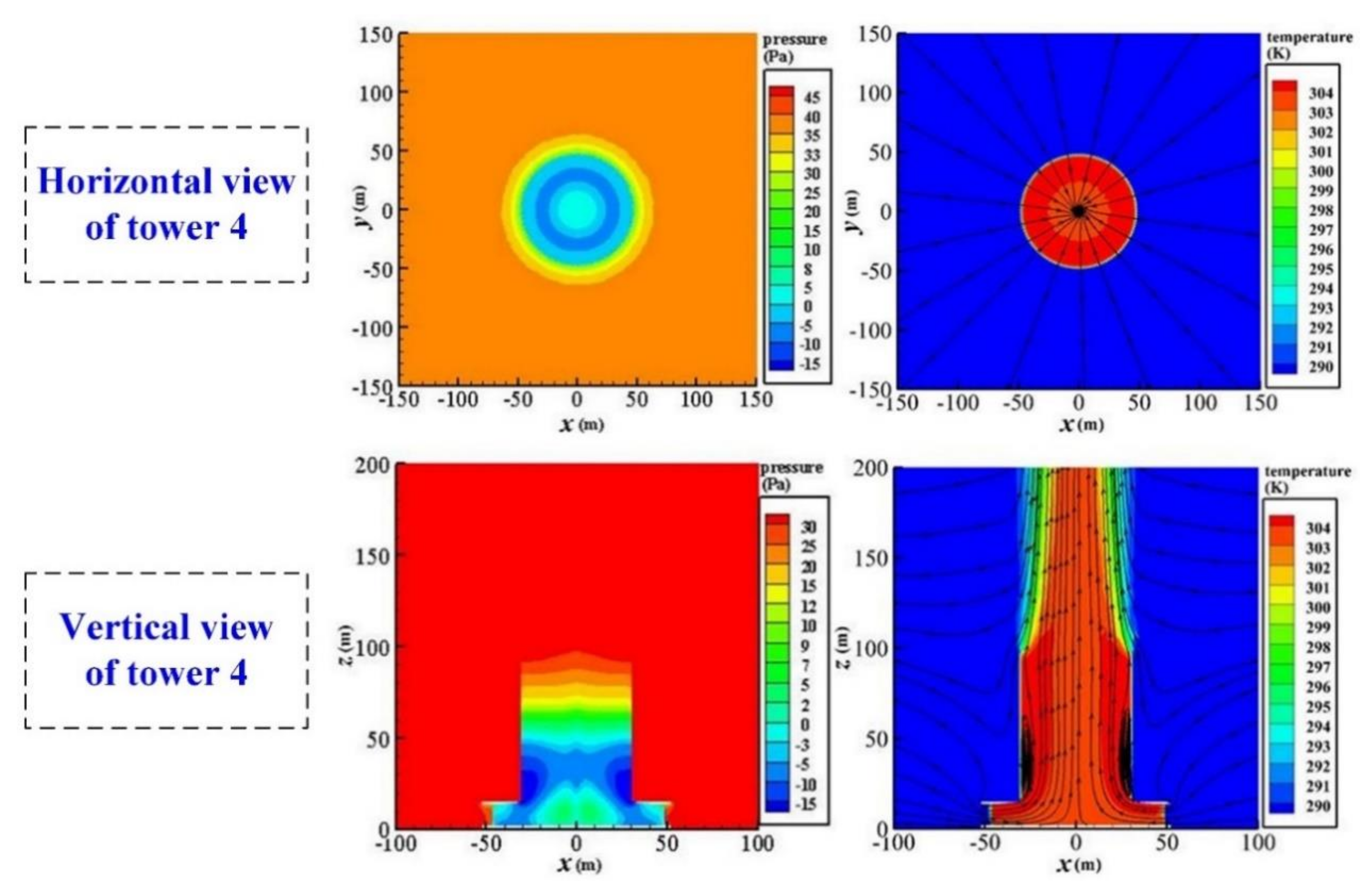
3.1.1. Without Ambient Wind

Figure 6, Figure 7, Figure 8 and Figure 9 display the air variable contours of steel-tower NDDCSs with the four typical tower configurations in the absence of wind. For all tower configuration cases, the uniform reverse pressure gradients inside the cooling tower are formed to overcome the air flow resistance of ACHE, and then the centrally symmetric air flow and temperature fields are generated. With regard to tower 1, shown in Figure 6, the pressure difference between the inner and outer sides of ACHE was nearly 45 Pa. The reverse pressure near the ACHE and the bottom of cooling tower ranged from −15 Pa to −3 Pa. As for tower 2, Figure 7 presents the pressure difference, which equaled about 33 Pa, and was slightly lower than tower 1. In addition, the reverse pressure area was also smaller. Additionally, the air temperature contours of tower 1 and tower 2 were almost the same. Tower 3 in Figure 8 had similar temperature and pressure contours to tower 1. The slightly decreased flow and temperature fields of tower 2 and tower 3 came from the declined air flow stability with the only cylindrical section near the tower outlet, while tower 4, with the cylindrical configuration, showed an obviously smaller pressure difference in the ACHE, only 28 Pa. Furthermore, the big vortices also emerged adjacent to the turning corner near the tower bottom, and the phenomena ultimately incurred hot air recirculation, as observed in Figure 9. The seriously deteriorated air variable fields were caused by the sudden change of air flow direction with the sharp corner.

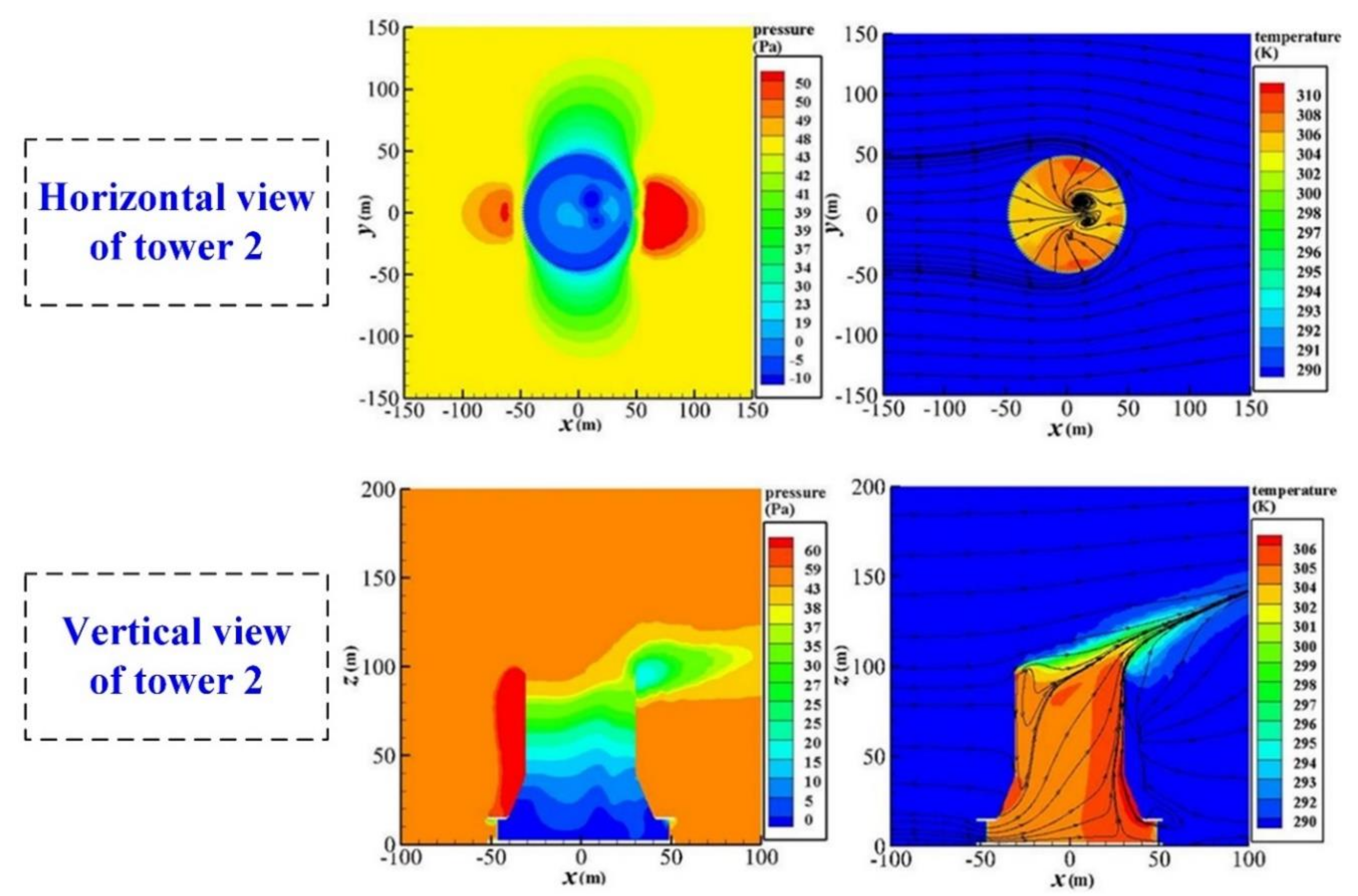
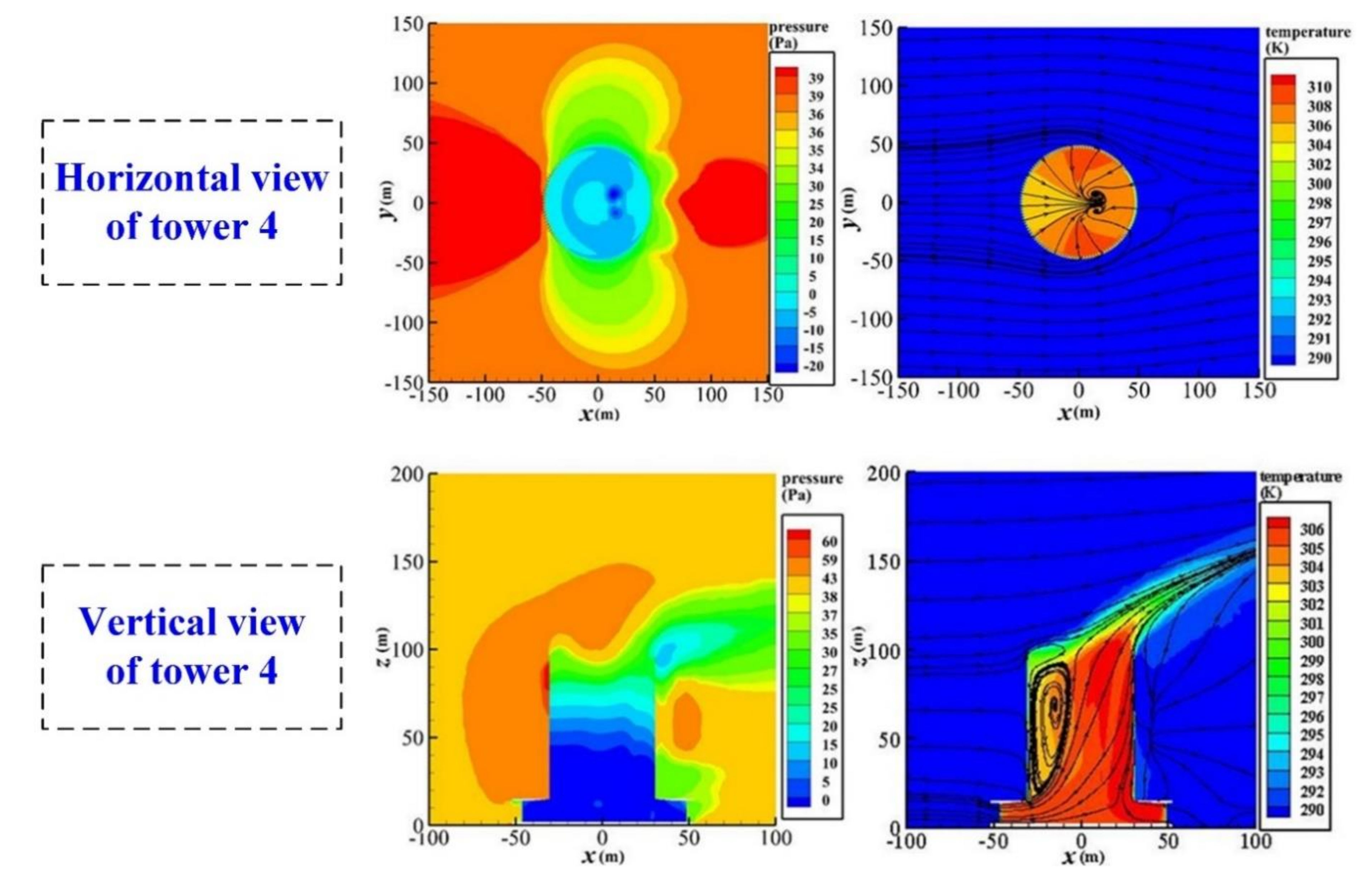
3.1.2. At Design Crosswind of 4 m/s

Figure 10, Figure 11, Figure 12 and Figure 13 show the air variable contours for steel-tower NDDCSs with the four typical tower configurations under a design ambient wind of 4 m/s. With various tower configurations, cooling systems always present larger pressure differences in the windward air-cooled sectors compared to the lateral and leeward ones. Furthermore, the air flow discharge at the tower exit became weak due to the crosswind impacts. Compared to tower 1, tower 2 had a relatively smaller high-pressure area near the windward air-cooled sectors, while the low-pressure area near the lateral air-cooled sectors became slightly larger, as shown in Figure 10 and Figure 11. Consequently, for tower 2 configuration, the air outlet temperature of the windward sectors appeared lower, whereas it was shown to be higher in the lateral air-cooled sectors. Additionally, some reverse flows emerged near the tower outlet because of the decreased pressure increase effects, which lead to adverse effects on the air mass flow rate. These variable phenomena imply that the conical/cylindrical configuration may have a lower cooling efficiency when compared with the traditional tower configuration. It can be seen in Figure 12, tower 3 had nearly similar air variable contours with tower 1, while the vertical view exhibited the reverse flow with vortex near the tower outlet. Tower 4, as given in Figure 13, presented an evidently lower pressure difference and air outlet temperature near the windward sectors. Meanwhile, the outlet air temperature near the lateral and leeward air-cooled sectors became apparently higher. Furthermore, the big vortices were generated near the tower outlet, which will cripple air flow significantly. Such adverse thermo-flow fields originated from significantly decreased buffering effects. These air flow and temperature fields predicted that the completely cylindrical tower configuration would have negative impact on the thermal process of the steel-truss NDDCS. Concluding from those aforementioned analyses, the traditional hyperbolic cooling tower possesses better cooling performance than the other tower configurations.

3.2. Distributions of Local Thermal and Flow Behaviors

Based on those aforementioned variable contours, the mass flow of cooling air, as well as the heat rejection for the local sectors, are presented in Figure 14 for both the tower 1 configuration and the tower 4 configuration. These two steel-truss natural draft dry cooling systems had similar thermo-flow distributions among various air-cooled sectors. This implies that the tower configuration will not change the influencing trend of the crosswind on ACHE. As can also be observed, when the ambient wind became strengthened, the air flow and cooling capability for the windward sectors No. 5 and No. 6 increased, which, however, dropped heavily for the lateral sectors No. 3 and No. 8. In addition, compared with tower 1, tower 4, with the cylindrical configuration, had apparently declined thermal and flow results for nearly all local sectors, which verified the aforementioned air variable contours.

3.3. Comparisons of Overall Thermal and Flow Performances

The dimensionless parameters of the total air flow rate δm and also the total heat transfer rate δΦ are given for comparing the overall thermal and flow behaviors of the four steel-truss NDDCSs with the typical cooling tower configurations.
δ m = m a i m a 1 m a 1 × 100 %
δ Φ = Φ i Φ 1 Φ 1 × 100 %
where ma1 and Φ1 represent the total air flow rate and also the total heat transfer rate for tower 1 with the traditional hyperbolic configuration, meanwhile mai and Φi mean the total air flow rate and the total heat rejection for other tower configurations.
The comparisons of the overall thermal and flow performances for the four steel-truss NDDCSs under various ambient wind conditions are provided. It can be concluded from Figure 15 that both non-dimensional air flow rate and heat transfer rate for tower 2 were a little negative, resulting from the slightly worse air variable fields. Tower 3 had the better cooling performance under the high crosswinds, which differed from the results under other crosswind conditions; whereas, for tower 4, the thermo-flow performance was shown to be apparently worse than the other tower configurations with much lower negative parameters.

4. Conclusions

This investigation paid attention to the thermal and flow behaviors for the steel-truss NDDCSs with four typical engineering tower configurations by numerical modeling. For these steel-truss natural draft dry cooling systems, the air variable contours were analyzed, the local air flow rate and heat transfer rate were presented, and the overall thermal and flow performances were compared. The main findings are summarized as follows:
(1)
In absence of wind, tower 2 presented slightly lower pressure difference in ACHE than tower 1. Tower 3 had similar pressure and temperature fields with tower 1, while tower 4 showed a much smaller pressure difference, and the big vortices also emerged adjacent to the turning corner of cooling tower.
(2)
At a design crosswind of 4 m/s, tower 2 displayed a smaller area of high pressure near the windward sectors, It also had a larger area of low pressure near the lateral sectors than tower 1. The vertical air flow fields of tower 3 showed some reverse flows with vortices near the tower outlet, which became fairly big inside tower 4.
(3)
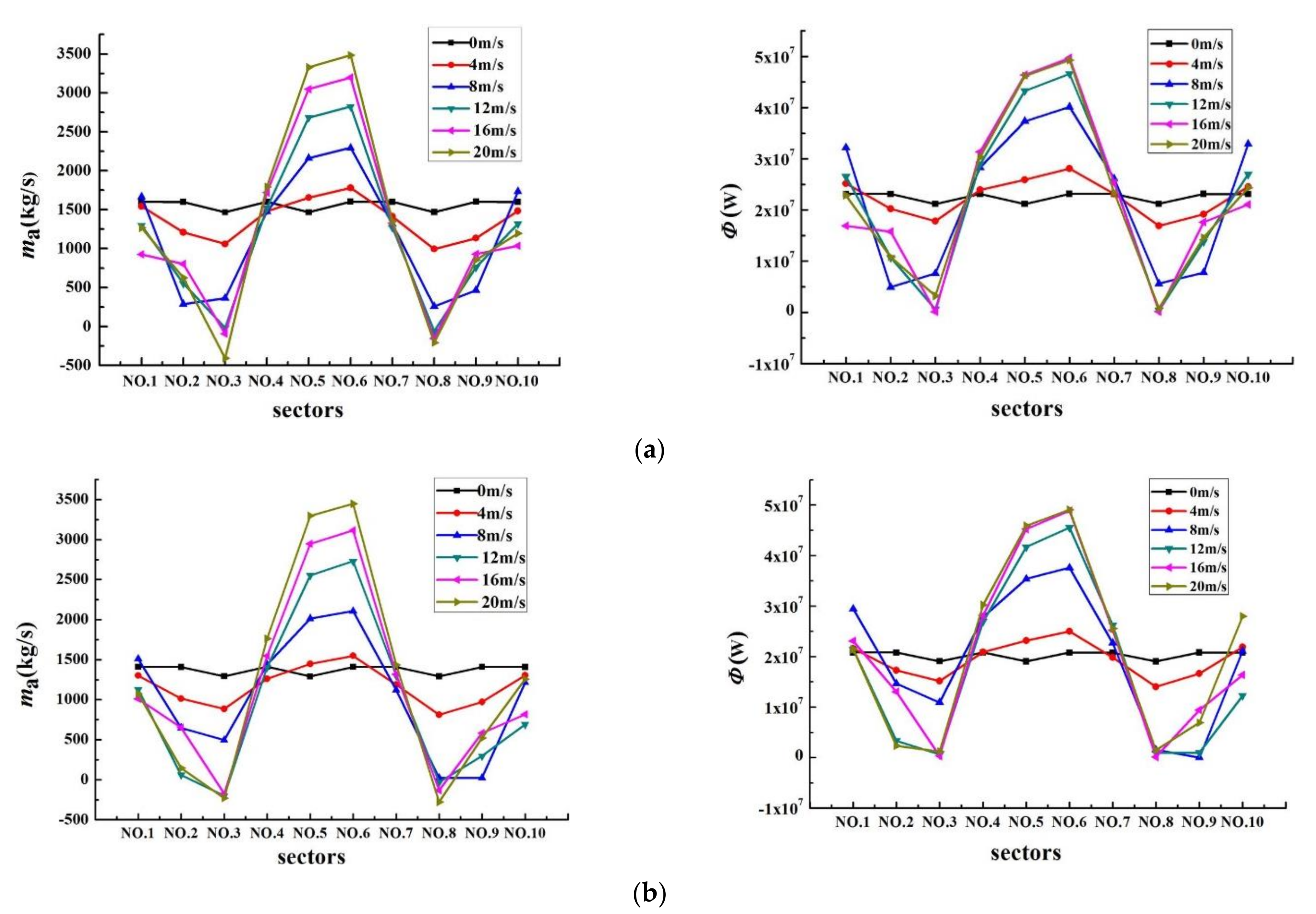
Tower configuration did not change the trend of crosswind impacts on ACHE. Compared with tower 1, tower 4 had apparently lower air flow rate and heat transfer rate for nearly all local sectors.
(4)
The non-dimensional thermal and flow parameters of tower 2 were slightly negative, whereas, tower 3 presented better cooling performance under high crosswinds. Tower 4 had the worst overall thermo-flow performances compared with the other tower configurations.
For engineering application of the steel-truss natural draft dry cooling system, the traditional hyperbolic tower configuration is recommended for areas with a commonly small crosswind, while for those regions with frequently high crosswinds, the hyperbolic/cylindrical tower configuration is preferred.

Author Contributions

Conceptualization, H.G. and W.W.; methodology, T.C.; software, Y.Y. and H.Z.; formal analysis, H.G.; resources, W.W.; writing—original draft preparation, W.W.; writing—review and editing, W.W.; supervision, X.D.; project administration, X.D. All authors have read and agreed to the published version of the manuscript.

Funding

This research received no external funding.

Acknowledgments

The financial supports for this research, from the National Natural Science Foundation of China (Grant No. 52006055) and the Basic Research Foundation of Central Universities (Grant No. 2019QN023), are gratefully acknowledged.

Conflicts of Interest

The authors declare no conflict of interest.

Nomenclature

Ddiameter (m)
Hheight (m)
Hconvective heat transfer coefficient (W m−2 K−1)
Kflow loss coefficient
Ltube length (m)
Mmolecular weight (g mol−1)
Mmass flow rate (kg s−1)
NNumber
Ppressure (Pa)
Runiversal gas constant (J mol−1 K−1)
Ssource term in generic equation
ttemperature (K)
uvelocity (m s−1)
Vvolume (m3)
xcoordinate axis
Greek symbols
Γdiffusion coefficient (m2 s−1)
Φheat rejection rate (W)
φscalar variable
ρdensity (kg m−3)
Subscripts
aAir
jcoordinate direction
refReference
windCrosswind
waWater
1Inlet
2Outlet
Acronyms
ACHEair-cooled heat exchanger
NDDCSnatural draft dry cooling system

References

  1. Li, X.X.; Gurgenci, H.; Guan, Z.Q.; Wang, X.R.; Xia, L. A review of the crosswind effect on the natural draft cooling towers. Appl. Therm. Eng. 2019, 150, 250–270. [Google Scholar] [CrossRef]
  2. Wang, W.J.; Yang, L.J.; Du, X.Z.; Yang, Y.P. Anti-freezing water flow rates of various sectors for natural draft dry cooling system under wind conditions. Int. J. Heat Mass Transf. 2016, 102, 186–200. [Google Scholar] [CrossRef]
  3. Yu, Q.Q.; Gu, X.L.; Li, Y.; Lin, F. Collapse-resistant performance of super-large cooling towers subjected to seismic actions. Eng. Struct. 2016, 102, 77–89. [Google Scholar] [CrossRef]
  4. Ma, H.H.; Li, Z.Y.; Li, S.Z.; San, B.B.; Fan, F. Stability analysis and performance comparison of large-scale hyperbolic steel cooling towers with different latticed shell systems. J. Constr. Steel Res. 2019, 160, 559–578. [Google Scholar] [CrossRef]
  5. Ma, H.H.; Zhao, Y.; Fan, F.; Yu, Z.W.; Zhi, X.D. Experimental and numerical study of new connection systems for a large-span hyperbolic steel cooling tower. Eng. Struct. 2019, 195, 452–468. [Google Scholar] [CrossRef]
  6. Ma, T.T.; Zhao, L.; Chen, N.Y.; Ge, Y.J.; Zhang, D. Wind-induced dynamic performance of a super-large hyperbolic steel-truss cooling tower. Thin-Walled Struct. 2020, 157, 107061. [Google Scholar] [CrossRef]
  7. Ma, H.H.; Li, S.Z.; Fan, F. Static performance analysis of single-layer steel cooling tower. Structures 2019, 19, 322–332. [Google Scholar] [CrossRef]
  8. Song, G.Q.; Zhi, X.D.; Fan, F.; Wang, W.; Wang, P. Cooling performance of cylinder-frustum natural draft dry cooling tower. Appl. Therm. Eng. 2020, 180, 115797. [Google Scholar] [CrossRef]
  9. Zhao, Y.B.; Long, G.Q.; Sun, F.Z.; Li, Y.; Zhang, C.J. Numerical study on the cooling performance of dry cooling tower with vertical two-pass column radiators under crosswind. Appl. Therm. Eng. 2015, 75, 1106–1117. [Google Scholar] [CrossRef]
  10. Zhao, Y.B.; Sun, F.Z.; Li, Y.; Long, G.Q.; Yang, Z. Numerical study on the cooling performance of natural draft dry cooling tower with vertical delta radiators under constant heat load. Appl. Energy 2015, 149, 225–237. [Google Scholar] [CrossRef]
  11. Ma, H.; Si, F.Q.; Kong, Y.; Zhu, K.P.; Yan, W.S. A new theoretical method for predicating the part-load performance of natural draft dry cooling towers. Appl. Therm. Eng. 2015, 78, 1106–1115. [Google Scholar] [CrossRef] [Green Version]
  12. Li, X.X.; Gurgenci, H.; Guan, Z.Q.; Sun, Y.B. Experimental study of cold inflow effect on a small natural draft dry cooling tower. Appl. Therm. Eng. 2018, 128, 762–771. [Google Scholar] [CrossRef] [Green Version]
  13. Goodarzi, M.; Amooie, H. Heat transfer enhancement in a natural draft dry cooling tower under crosswind operation with heterogeneous water distribution. Int. J. Nucl. Power 2016, 61, 252–259. [Google Scholar]
  14. Wang, X.B.; Yang, L.J.; Du, X.Z.; Yang, Y.P. Performance improvement of natural draft dry cooling system by water flow distribution under crosswinds. Int. J. Heat Mass Transf. 2017, 108, 1924–1940. [Google Scholar] [CrossRef]
  15. Li, X.X.; Xia, L.; Gurgenci, H.; Guan, Z.Q. Performance enhancement for the natural draft dry cooling tower under crosswind condition by optimizing the water distribution. Int. J. Heat Mass Transf. 2017, 107, 271–280. [Google Scholar] [CrossRef]
  16. Zhao, Y.B.; Long, G.Q.; Sun, F.Z.; Li, Y.; Zhang, C.J.; Liu, J.B. Effect mechanism of air deflectors on the cooling performance of dry cooling tower with vertical delta radiators under crosswind. Energy Convers. Manag. 2015, 93, 321–331. [Google Scholar] [CrossRef]
  17. Chen, L.; Yang, L.J.; Du, X.Z.; Yang, Y.P. Performance improvement of natural draft dry cooling system by interior and exterior windbreaker configurations. Int. J. Heat Mass Transf. 2016, 96, 42–63. [Google Scholar] [CrossRef]
  18. Gu, H.F.; Wang, H.J.; Gu, Y.Q.; Yao, J.N. A numerical study on the mechanism and optimization of wind-break structures for indirect air-cooling towers. Energy Convers. Manag. 2016, 108, 43–49. [Google Scholar] [CrossRef]
  19. Wang, W.L.; Zhang, H.; Li, Z.; Lv, J.F.; Ni, W.D.; Li, Y.S. Adoption of enclosure and windbreaks to prevent the degradation of the cooling performance for a natural draft dry cooling tower under crosswind conditions. Energy 2016, 116, 1360–1369. [Google Scholar] [CrossRef]
  20. Wang, W.L.; Zhang, H.; Liu, P.; Li, Z.; Lv, J.F.; Ni, W.D. The cooling performance of a natural draft dry cooling tower under crosswind and an enclosure approach to cooling efficiency enhancement. Appl. Energy 2017, 186, 336–346. [Google Scholar] [CrossRef]
  21. Ma, H.; Si, F.Q.; Kong, Y.; Zhu, K.P.; Yan, W.S. Wind-break walls with optimized setting angles for natural draft dry cooling tower with vertical radiators. Appl. Therm. Eng. 2017, 112, 326–329. [Google Scholar] [CrossRef] [Green Version]
  22. Ma, H.; Si, F.Q.; Zhu, K.P.; Wang, J.S. The adoption of windbreak wall partially rotating to improve thermo-flow performance of natural draft dry cooling tower under crosswind. Int. J. Therm. Sci. 2018, 134, 66–88. [Google Scholar] [CrossRef]
  23. Wu, T.; Ge, Z.H.; Yang, L.J.; Du, X.Z. Flow deflectors to release the negative defect of natural wind on large scale dry cooling tower. Int. J. Heat Mass Transf. 2019, 128, 248–269. [Google Scholar] [CrossRef]
  24. Xia, L.; Gurgenci, H.; Liu, D.Y.; Guan, Z.Q.; Zhou, L.; Wang, P. CFD analysis of pre-cooling water spray system in natural draft dry cooling towers. Appl. Therm. Eng. 2016, 105, 1051–1060. [Google Scholar] [CrossRef] [Green Version]
  25. Chen, L.; Huang, X.W.; Yang, L.J.; Du, X.Z.; Yang, Y.P. Evaluation of natural draft dry cooling system incorporating water spray air precooling. Appl. Therm. Eng. 2019, 151, 294–307. [Google Scholar] [CrossRef]
  26. Huang, X.W.; Chen, L.; Yang, L.J.; Du, X.Z.; Yang, Y.P. Evaporation aided improvement for cooling performance of large scale natural draft dry cooling system. Appl. Therm. Eng. 2019, 163, 114350. [Google Scholar] [CrossRef]
  27. Dong, P.X.; Li, X.X.; Sun, Y.B.; Hooman, K.; Guan, Z.Q.; Dai, Y.C.; Gurgenci, H. Numerical investigation of the influence of local effects on the transient start-up process of natural draft dry cooling towers in dispatchable power plants. Int. J. Heat Mass Transf. 2019, 133, 166–178. [Google Scholar] [CrossRef]
  28. Dong, P.X.; Li, X.X.; Hooman, K.; Sun, Y.B.; Li, J.S.; Guan, Z.Q.; Gurgenci, H. The crosswind effects on the start-up process of natural draft dry cooling towers in dispatchable power plants. Int. J. Heat Mass Transf. 2019, 135, 950–961. [Google Scholar] [CrossRef]
  29. Dai, Y.C.; Kaiser, A.S.; Lu, Y.S.; Klimenko, A.Y.; Dong, P.X.; Hooman, K. Addressing the adverse cold air inflow effects for a short natural draft dry cooling tower through swirl generation. Int. J. Heat Mass Transf. 2019, 145, 118738. [Google Scholar] [CrossRef]
  30. Kong, Y.Q.; Wang, W.J.; Yang, L.J.; Du, X.Z.; Yang, Y.P. Water redistribution among various sectors to avoid freezing of air-cooled heat exchanger. Int. J. Heat Mass Transf. 2019, 141, 294–309. [Google Scholar] [CrossRef]
  31. Wang, W.J.; Kong, Y.Q.; Huang, X.W.; Yang, L.J.; Du, X.Z.; Yang, Y.P. Anti-freezing of air-cooled heat exchanger by switching off sectors. Appl. Therm. Eng. 2017, 120, 327–339. [Google Scholar] [CrossRef]
  32. Wang, W.J.; Huang, X.W.; Yang, L.J.; Du, X.Z.; Yang, Y.P. Anti-freezing operation strategies of natural draft dry cooling system. Int. J. Heat Mass Transf. 2018, 118, 165–170. [Google Scholar] [CrossRef]
  33. Li, W.D.; Wang, H.T.; Wang, J.; Duan, C.P.; Zhao, Y.B. Effect mechanism of exit-water temperature distribution characteristics on the anti-freezing of natural draft dry cooling tower. Appl. Therm. Eng. 2019, 161, 114078. [Google Scholar] [CrossRef]
  34. Ma, H.; Si, F.Q.; Zhu, K.P.; Wang, J.S. Utilization of partial through-flow tower shell to cope with the excess cooling capacity of dry cooling tower in extremely cold days with crosswind. Int. J. Therm. Sci. 2019, 136, 70–85. [Google Scholar] [CrossRef]
  35. Zhou, J.X.; Ma, H.; Si, F.Q.; Zhu, K.P.; Wang, J.S. To broaden safe operation range of the indirect dry cooling system with internal annular windbreak cloth in extremely cold days. Appl. Therm. Eng. 2019, 152, 420–429. [Google Scholar] [CrossRef]
  36. Hong, G.; Kim, C.; Hong, J. Energy conservation potential of economizer controls using optimal outdoor air fraction based on field study. Energies 2020, 13, 5038. [Google Scholar] [CrossRef]
  37. Shumaev, V.V.; Kuzenov, V.V. Development of the numerical model for evaluating the temperature field and thermal stresses in structural elements of aircrafts. J. Phys. Conf. Ser. 2017, 891, 012311. [Google Scholar] [CrossRef]
  38. Ryzhkov, S.V.; Kuzenov, V.V. Analysis of the ideal gas flow over body of basic geometrical shape. Int. J. Heat Mass Transf. 2019, 132, 587–592. [Google Scholar] [CrossRef]
Figure 1. Steel-truss natural draft dry cooling system (NDDCSs) with different tower configurations.
Energies 14 02002 g001
Figure 2. Schematic of air-cooled sector distribution.
Energies 14 02002 g002
Figure 3. Illustrative computational domain of tower 2 with conical/cylindrical configuration.
Energies 14 02002 g003
Figure 4. Numerical iteration process for various steel-truss cooling systems.
Energies 14 02002 g004
Figure 5. Distribution of the measuring positions in cooling tower and the comparison of the numerical and experimental air flow velocities [2,14,17].
Energies 14 02002 g005
Figure 6. Air variable contours for steel-truss NDDCS with hyperbolic tower configuration without ambient wind.
Energies 14 02002 g006
Figure 7. Air variable contours for steel-truss NDDCS with conical/cylindrical tower configuration without ambient wind.
Energies 14 02002 g007
Figure 8. Air variable contours for steel-truss NDDCS with hyperbolic/cylindrical tower configuration without ambient wind.
Energies 14 02002 g008
Figure 9. Air variable contours for steel-truss NDDCS with cylindrical tower configuration without ambient wind.
Energies 14 02002 g009
Figure 10. Air variable contours for steel-truss NDDCS with hyperbolic tower configuration at design crosswind of 4 m/s.
Energies 14 02002 g010
Figure 11. Air variable contours for steel-truss NDDCS with conical/cylindrical tower configuration at design crosswind of 4 m/s.
Energies 14 02002 g011
Figure 12. Air variable contours for steel-truss NDDCS with hyperbolic/cylindrical tower configuration at design crosswind of 4 m/s.
Energies 14 02002 g012
Figure 13. Air variable contours for steel-truss NDDCS with cylindrical tower configuration at design crosswind of 4 m/s.
Energies 14 02002 g013
Figure 14. Distributions of local thermal and flow behaviors for air-cooled sectors of tower 1 configuration and tower 4 configuration. (a) Tower 1; (b) tower 4.
Energies 14 02002 g014
Figure 15. Comparisons of the overall thermal and flow parameters for the four tower configurations. (a) Non-dimensional total mass flow of cooling air; (b) non-dimensional total heat transfer rate.
Energies 14 02002 g015
Publisher’s Note: MDPI stays neutral with regard to jurisdictional claims in published maps and institutional affiliations.

