Article

A Novel Multi-Area Distribution State Estimation Approach for Active Networks

by
Mohammad Gholami
1,
Ali Abbaspour Tehrani-Fard
1,
Matti Lehtonen
2,*,
Moein Moeini-Aghtaie
3 and
Mahmud Fotuhi-Firuzabad
1
1
Department of Electrical Engineering, Sharif University of Technology, Azadi Ave., Tehran 15119-43943, Iran
2
Department of Electrical Engineering, Aalto University, P.O. Box 15500, 00076 Espoo, Finland
3
Department of Energy Engineering, Sharif University of Technology, Azadi Ave., Tehran 15119-43943, Iran
*
Author to whom correspondence should be addressed.
Energies 2021, 14(6), 1772; https://doi.org/10.3390/en14061772
Submission received: 25 February 2021 / Revised: 15 March 2021 / Accepted: 19 March 2021 / Published: 23 March 2021
(This article belongs to the Special Issue Load Modelling of Power Systems)

Abstract

:
This paper presents a hierarchically distributed algorithm for the execution of distribution state estimation function in active networks equipped with some phasor measurement units. The proposed algorithm employs voltage-based state estimation in rectangular form and is well-designed for large-scale active distribution networks. For this purpose, as the first step, the distribution network is supposed to be divided into some overlapped zones and local state estimations are executed in parallel for extracting operating states of these zones. Then, using coordinators in the feeders and the substation, the estimated local voltage profiles of all zones are coordinated with the local state estimation results of their neighboring zones. In this regard, each coordinator runs a state estimation process for the border buses (overlapped buses and buses with tie-lines) of its zones and based on the results for voltage phasor of border buses, the local voltage profiles in non-border buses of its zones are modified. The performance of the proposed algorithm is tested with an active distribution network, considering different combinations of operating conditions, network topologies, network decompositions, and measurement scenarios, and the results are presented and discussed.

1. Introduction

Over recent years, distribution networks are encountering some new events, i.e., the existence of distributed generating (DG) units, local energy markets, the presence of new distributed energy resources, and prosumers [1]. These events can be translated to a gradual evolution from passive into active distribution networks. In this condition, the flow of distribution feeders will be bi-directional and the advantages of radial topology will be diminished. Therefore, the structure of distribution networks gradually should be reshaped from a mainly radial to a more meshed topology aimed to keep the reliability level of the system [2]. On the other hand, the stochastic and intermittent nature of the renewable energy sources (solar and wind) with the significant and continuous growth rate primarily due to the environmental concerns, can lead to abrupt changes in the net load of the distribution network and, as a result, flexibility issues (generation capacity adequacy) [1,3,4]. As a result, the system operators and planners need to deal with highly complex active distribution networks (ADNs) [2].
In this situation, the distribution management system (DMS) with low visibility and automation levels cannot meet the challenges of the ADNs. Therefore, active DMSs need to be developed to effectively monitor, control, and protect the network [5]. These systems are based on situation awareness of the network. Taking into consideration the fact that it is not economical to equip all buses of the distribution network with measurement devices, distribution state estimation plays an inevitable role in the effective performance of active DMS. State estimation (SE) is a process of applying inaccurate and available measurements and information to extract the best estimation of system operational conditions [6]. However, most of the SE algorithms use the centralized approach and due to the large number of network buses and the growing amount of available information in ADNs, they may face the following issues [7]
  • Requiring high computational speed processors;
  • Requiring large data storage units;
  • Requiring a low latency communication system to transfer large amounts of data among the field agents and control center;
  • Subjecting to a single point of failure risk.
In contrast, decentralized strategies are more popular in the case of large networks and besides the elimination of centralized strategy’s weaknesses, they can increase the reliability, flexibility, and efficiency of SE (and also DMS) [7]. As a result, regarding the main features accounted for decentralized strategies, several algorithms have been proposed in the literature [8,9,10,11,12,13]. However, most of these proposed methods are designed for transmission systems, and according to the following reasons, they cannot be used directly in the distribution system:
  • Usually, real-time measurements in the distribution network are limited;
  • Unlike transmission systems, a large share of consumed energy in the distribution network is fed through the upstream substations. Consequently, despite the existence of normally closed tie-lines in ADNs with meshed topology, hierarchical strategies will play an effective role in the coordination phase of decentralized SE procedures;
  • Generally, the division of the network is mainly performed according to the topological and geographical criteria. On the other hand, there is a flexible topology in the ADNs by switching tie-lines. However, the base topology of the network is radial, and the internal buses of zones resulting from the division of the network should belong to the same feeder.
In response, a few methods have been proposed in the literature to perform decentralized SE in distribution networks [14,15,16,17,18]. In [14], a differential evolution algorithm-based SE is suggested, which leads to its global estimation through information exchange between local estimators in each iteration. Additionally, an overlapping zone approach for the parallelization of SE is presented in [15]. This method, however, requires many zonal information exchanges and consequently needs strong communication support. More recently, some two-step multi-area SE procedures that employ distributed strategy, have been proposed in [16,17,18]. For this purpose, as the first step, each local estimator approximates the currents of its local branches along with its reference node voltage. Then, the coordination between calculated local states is performed on the second step by running another SE process for all zones in parallel after information exchange between neighboring areas. However, in these approaches, it is assumed that the network topology is radial and their performance in the ADNs with mesh topology has not been investigated.
To address these issues and reach a more efficient scheme, a new Hierarchically Distributed SE (HDSE) procedure is presented to assess network states. As will be shown in later sections, the proposed method leads to the SE results with lower levels of uncertainty at efficient execution time and improves the reliability and latency of the communication infrastructures (CIs) due to employment of the hierarchical strategy. The proposed method employs voltage-based SE in the rectangular form, which is completely suited for ADNs. In this regard, at first, a distribution network is supposed to be divided into some overlapped zones, and each zone estimator (ZE) calculates its local states in parallel without any information exchange between neighboring zones. Then, the local voltage estimations in neighboring zones are coordinated using the substation coordinator (SC) and feeder coordinators (FCs). Indeed, all zones in each feeder of the network are divided into two groups: FCR zones (zones that are revised by FCs) and SCR zones (zones that are revised by SC). Then, the FC and SC attend to coordinate the local voltage estimation of their related ZEs. To reach this goal, as the first step, the SC and FCs revise the results of ZEs in border buses by running another SE on their corresponding sub-networks, which include only overlapped elements and tie-lines. Finally, a new algorithm for modifying the voltage profile of non-border buses (internal buses) in each zone is proposed using coordinated voltage estimations of border buses. The accuracy and running time of the proposed algorithm are put under investigation by comparing this method with integrated SE, local SE without coordination phase, and traditional methods in the literature, considering different operating conditions.
The main contributions of this paper can be summarized as follow:
  • Introducing a new HDSE procedure for improving the accuracy of SE results and the reliability and latency of CISs’ in ADNs;
  • Proposing a new approach for modifying the local voltage estimation of the zone’s internal buses according to the coordinated results of border buses;
  • Considering the existence of normally closed tie-lines (networks with meshed topology) in the proposed decentralized SE method for ADNs.
The rest of this paper is organized as follows. Section 2 describes the process of SE in ADN. The proposed procedure for decentralized implementation of SE in ADNs is described in Section 3. The information related to the case study, simulation assumptions, load flow results of the test case, accuracies of the SE results, and the performance evaluation of the proposed and traditional methods in different considered scenarios are presented in Section 4. Finally, after the discussion about the obtained simulation results in Section 5, the conclusion is presented in Section 6.

2. Active Distribution Networks State Estimation

State estimation is the process of employing real-time noisy measurements and available information of the network to optimally estimate the condition of the power system usually in form of the network voltage profile. In the distribution network, the basic input data of the SE process are historical and forecasted data (pseudo-measurements) and traditional measurements that are available on the substation. However, due to the inappropriate reporting rate and accuracy, this type of real-time measurement is not suitable for the SE process of ADNs and may lead to undesirable results. In this situation, accurate synchrophasors obtained from phasor measurement units (PMUs) and µPMUs can be employed [19,20].
In a distribution network, the procedure of SE is mainly based on weighted least squares (WLS), which tries to minimize the sum of the squares of weighted differences between actual measurements and the estimated ones [21]. The set of actual measurements in this method is considered by vector z
z = h ( x ) + e ,
where h T = [ h 1 ( x ) , h 2 ( x ) , , h m ( x ) ] , h i ( x ) is the function relating measurement i to the system state vector x T = [ x 1 , x 2 , , x n ] , and e T = [ e 1 , e 2 , , e m ] is the vector of measurement errors.
In linear SE, h i ( x ) is the linear function of state variables ( h ( x ) = H x ), and the following objective function is minimized [22]
J ( x ) = [ z H x ] T R 1 [ z H x ] ,
where R is the matrix of covariance measurement error.
Finally, the state vector can be estimated as:
x ^ = ( H T R 1 H ) 1 H T R 1 z .
In the SE problem, the key factor for optimizing the computational burden of the process is state variable selection. From this viewpoint, two types of SE process formulation generally exist in the literature: bus voltage-based and branch current-based formulations. Both of these estimators can be developed in both rectangular and polar coordinates, each one with some unique properties [23]. Based on the features of the voltage-based SE formulation in the rectangular form, i.e., matching with meshed topology, linear measurement function, and low computational burden as presented in [24], this type of estimator is employed for the extraction of system conditions.

3. Proposed Hierarchically Distributed SE

As explained before, decentralized control approaches are more efficient in the case of large-scale ADNs compared to centralized control strategies. To implement SE in a decentralized way, several strategies can be followed. The main differences between these strategies are the network splitting method, level of zone overlapping, computing architecture (series or parallel), and the way of local estimation coordination. Therefore, these strategies differ in terms of accuracy, amount of data exchange, characteristics of CIs, and computational speed. In this paper, a hierarchically distributed algorithm for performing decentralized SE in ADNs based on the following assumption is proposed:
  • The number and boundaries of zones in the network are predefined [16,17,18];
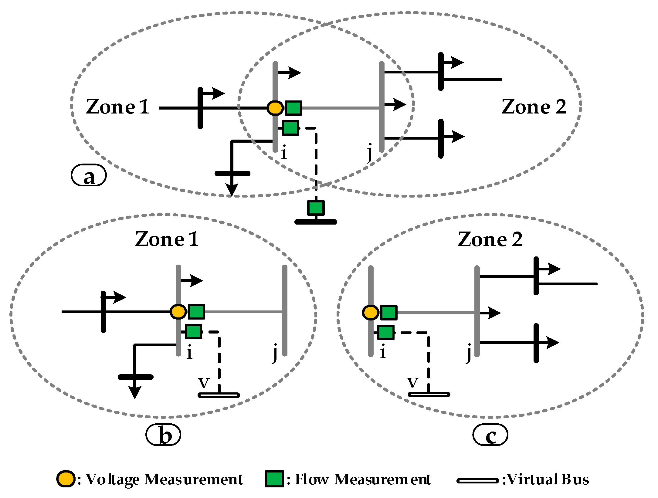
  • Each zone is equipped with adequate measurement devices to guarantee the observability of its local sub-network. Therefore, in the case of communication failure and loss of coordination phase, the states of each zone can be calculated with the minimum required data;
  • According to the proposed method in [21,25,26], bad data presence can be checked in each run of the local SE process. Elaborating on this issue in this paper is out of scope and interested readers can refer to these references for detailed information;
  • All voltage measurements in the overlapped buses (shared bus between neighboring zones) are taken by the PMUs or µPMUs. If only traditional measurements are used, due to lack of phase angle synchronization between zones, each zone estimator considers one of its internal buses as a slack bus, and the local SE process estimates the voltage phase angles of its local buses refer to this phase angle reference. Then, in the coordination phase, the zone which includes the substation bus is considered as the phase angle reference for other zones and according to the difference between voltage phase angle estimations in common buses of neighboring zones, the estimated voltage phase angles of the neighboring zone can be shifted sequentially.
Before introducing the architecture of the proposed method, some explanations about the network decomposition and the level of zone overlapping are presented in the following subsections.

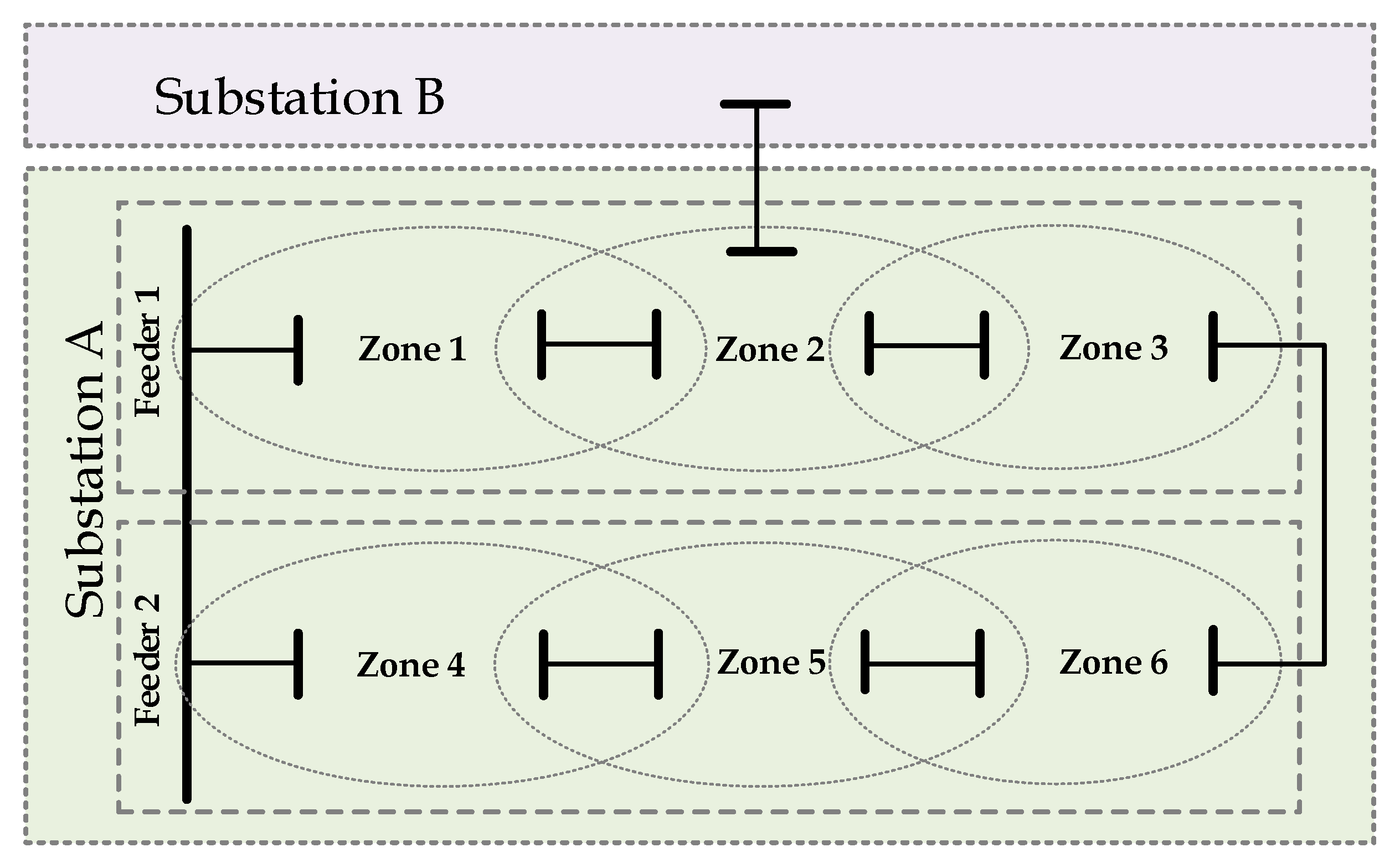
3.1. Level of Zone Overlapping

Generally, the decentralized SE procedure is based on the splitting network to several overlapped zones. To perform this decomposition, some factors should be taken into consideration:
  • Topological and geographical criteria;
  • The similarity of the zones size (for minimizing SE execution time);
  • Existence of overlapped bus and/or branch between zones for coordination of local estimates;
  • Existence of measurement devices in common buses to minimize the information exchange between neighboring zones.
In this paper, as shown in Figure 1a, the level of zone overlapping is restricted to a branch with its end buses (bus i and bus j). Besides, only voltage and power flow measurement devices are considered on one side of the common branch for minimizing the measurement and communication cost. In this situation, as shown in Figure 1b,c, the process of SE in each zone is independent of its neighboring zones. Therefore, the local states of each zone can be estimated without any information exchange between neighboring zones during the SE process.
In the proposed method, the boundary of each zone is limited to the buses and branches of only one feeder. In the case of tie-lines, each side of the tie-line should be equipped with a power flow measurement device. Consequently, in order to consider the power flow measurement of tie-lines in the SE process of the zone, virtual buses should be considered for each zone with tie-lines. In Figure 1a, the tie-line that connects bus i to bus k (in the neighboring feeder) is presented by the dashed line and considered in both zone 1 and zone 2 (Figure 1b,c), since it is connected to the common bus of these zones. In this situation, according to Figure 1, the measurement vectors, which are related to the bus i and bus j in the integrated SE (zcom), local SE of zone 1 (zcom1), and local SE of zone 2 (zcom2), can be represented by the following equations
z c o m = [ | V i | , V i Voltage   Meas . , P i j , Q i j , P i k , Q i k Power   Flow   Meas . , P i , Q i , P j , Q j Pseudo - meas . ]
z c o m 1 = [ | V i | , V i , P i j , Q i j , P i k , Q i k , P i , Q i ]
z c o m 2 = [ | V i | , V i , P i j , Q i j , P i k , Q i k , P j , Q j ] ,
where | V i | and V i are the voltage magnitude and phase angle in bus i, respectively; P i m and Q i m are active and reactive power flows between bus i and m for m { j , k } , respectively; Additionally, P n and Q n denote the injected active and reactive powers in bus n for n { i , j } , respectively.

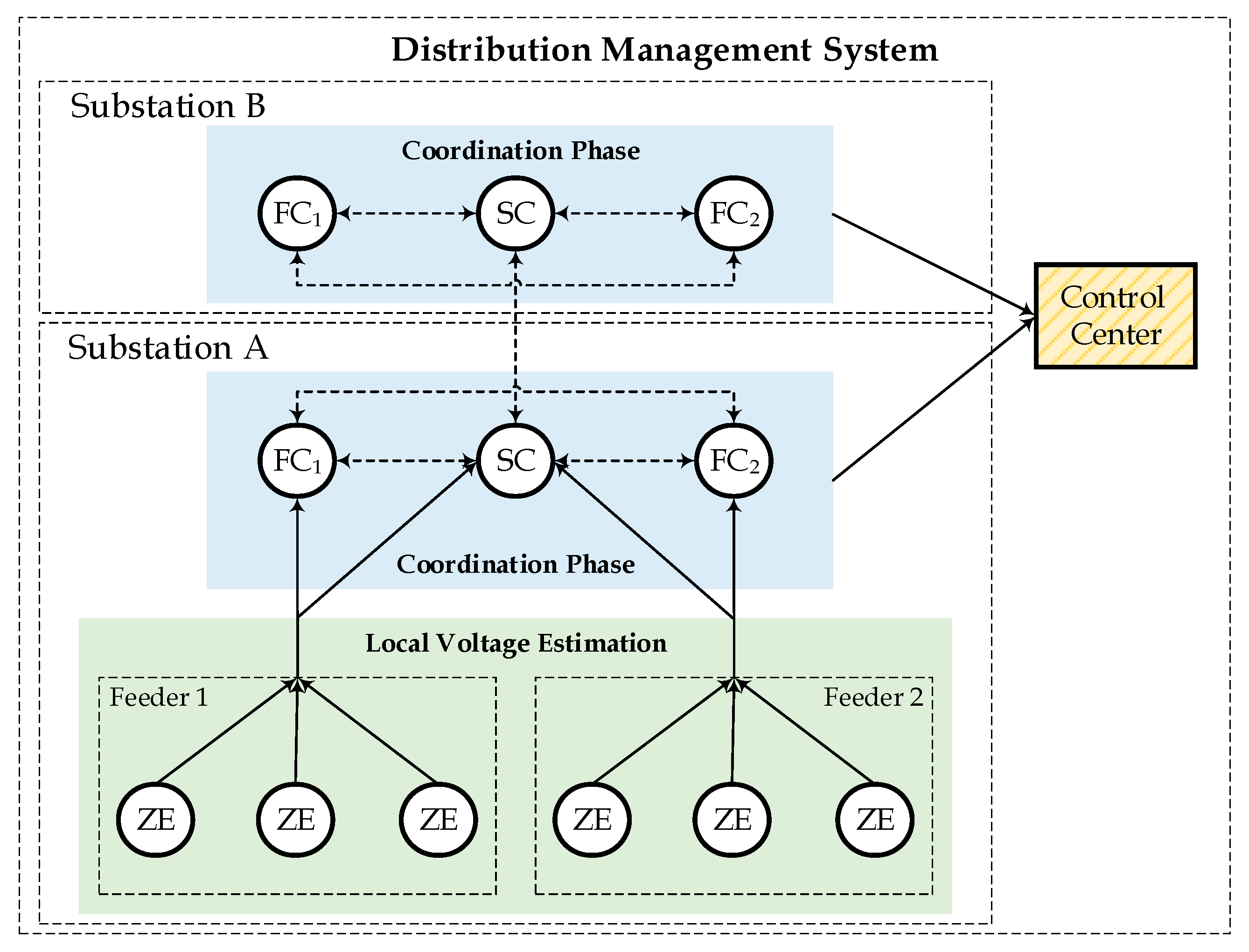
3.2. The Architecture of Proposed HDSE

In this paper, as shown in Figure 2, a hierarchically distributed architecture is introduced to run the SE process in a decentralized way using three autonomous computational units, i.e., Zone Estimator (ZE), Feeder Coordinator (FC), and Substation Coordinator (SC).
According to Figure 2, the final estimated states are attained based on two different steps: local voltage estimations and coordination of the local SE results. The ZEs in all zones of the network perform the first step of the proposed HDSE process. However, the duty of coordinating the local SE results is assigned to FCs and SCs units. Information exchange in the proposed structure is a combination of centralized and distributed strategies. Therefore, it is expected that this method integrates the advantages of both centralized and decentralized strategies and results in better accuracy than a distributed strategy. All of the FCs and the SC for each substation are proposed to be placed in the substation and use one shared database. Moreover, due to exploiting the hierarchical structure in the proposed method, in the cases that one of ZEs or FCs/SC units fails to perform its performance, their related FC/SC and the control center can be used as the backup unit, respectively.
In addition, due to the application of SE results in other functions of the DMS (like fault management and Volt/Var control), the estimated voltages in all decentralized approaches should be transmitted to the control center. Thus, the hierarchical part of the proposed architecture has no negative effect on the reliability and the latency of CIs. On the other hand, due to the elimination of data exchange between neighboring ZEs in different feeder or substation, the proposed scheme can improve these features in ADNs. Indeed, according to [27], the latency and reliability of CIs between sending and receiving units depend on the length of line sections and the number of buses that connect them (the route with minimum length). In the distributed implementation of SE, the local voltage estimation of border buses (overlapped buses and buses with tie-lines) should be exchanged between neighboring zones in two different feeders or substations for revising local voltage profiles in the coordination phase. However, as will be discussed later, these data exchanges in the proposed HDSE are limited between corresponding FCs/SCs.

3.3. Local Voltage Estimation

To execute the SE process in a decentralized way, this paper like most of the proposed strategies in the literature attends to estimate the voltage phasors of local buses in all zones independently. Indeed, after the division of the distribution feeder into some zones, each ZE estimates its local voltage profile in parallel without any information exchange between neighboring zones. The ZE executes the SE process for its local sub-network using local voltage measurements, power flow measurements and pseudo-measurements as inputs.
Also, according to the fact that estimated states on border buses are used as equivalent measurements in the coordination phase, the covariance matrix of estimated local states should be calculated in the last iteration of local SE as follows [7]
C o v ( x ) = d i a g ( [ H T R 1 H ] 1 ) .

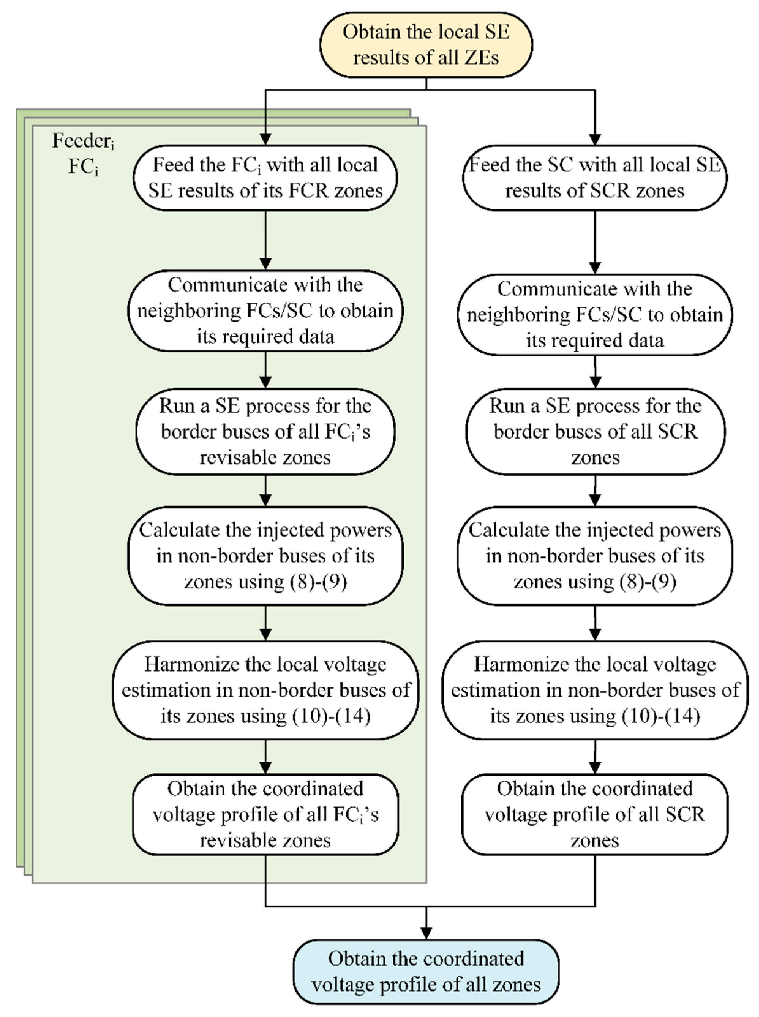
3.4. Coordination of the Local SE Results

Generally, due to the local processing of the network and its measured values, the accuracy of the voltage estimations in the local SE procedure (executed by ZE in the proposed method) is decreased in comparison with the centralized SE approach. In response, for improving the accuracy of the local SE results, coordination phases are considered in the decentralized applications of the SE process. According to the fact that neighboring local networks of the zones’ border buses are eliminated in the local SE process, the voltage estimation accuracy in these buses would be decreased. However, the situation for non-border buses of each zone is completely different. Indeed, as previously mentioned, the border buses of zones are equipped with accurate measuring elements to minimize the information exchange between neighboring zones. In this situation, due to the lack of measuring elements (or utilization of pseudo-measurements) in the non-border buses of zones, the voltage profile of each zone is estimated in a way that the measured values in the border buses are satisfied as much as possible. As a consequence, errors in the voltage estimation of border buses can cause inaccurate voltage estimation in non-border buses. Therefore, revising the voltage estimation of border buses after the execution of the local SE procedure plays an important role in the voltage profile improvement of all zones. In this regard, one of the famous approaches in the literature (we call it “Method 1” in the following sections) is to execute another SE process for the border buses of each zone after exchanging the local SE results of common buses between neighboring zones [7,28,29]. Then, the buses with the most accurate voltage magnitude and phase angle estimations in each zone are detected according to the results of the coordination phase in border buses (one bus for magnitude and one bus for phase angle). Finally, the voltage profile of non-border buses in each zone is shifted according to the differences between the local estimated value and coordinated value for detected buses.
On the other hand, since the procedure for harmonizing the voltage profile of zones’ non-border buses in Method 1 is the easiest approach, not the best one in terms of the results’ accuracy, some new approaches in the literature are proposed [16,17]. In these approaches, after exchanging the local SE results of shared buses between neighboring zones, another local SE process is executed for local networks using the estimated results of the considered zone and neighboring zones as new measurement inputs. However, the role of border buses in improving the voltage profile of zones is missed in these approaches and it seems that the execution of another local SE for local networks is unnecessary. This method for performing coordination is indicated as “Method 2” in the following sections.
In response, this paper attends to revise “Method 1” to improve the accuracy of voltage estimation in non-border buses. For this purpose, all zones in each feeder of the network are divided into two groups: FC’s revisable (FCR) zones and SC’s revisable (SCR) zones. Then, the FCs and SCs attend to coordinate the local voltage estimation of their related ZEs. Indeed, the first group of zones is coordinated by the related FC (there is one FC for each feeder). These zones do not include the substation bus or the buses that are connected to the neighboring substations (by tie-lines). However, the zones that fall into the second group include the aforementioned buses as a part of their border buses and are coordinated by the SC. In Figure 3, Zone 3 is the FCR zone of Feeder 1, and Zones 5 and 6 represent the FCR zones of Feeder 2 in a typical ADN; However, other zones of the network (Zones 1, 2, and 4) fall into the second group of zones (SCR zones).
The main responsibility of a FC/SC is to coordinate the local estimated voltage profile of its FCR/SCR zones with the outputs of ZEs in their neighboring zones using two different steps. The first coordination step of each FC/SC is to execute a SE process for a specific sub-network of the distribution network including the border buses of its related zones and the branches which connect them (as represented in Figure 3). It should be noted that the substation bus is a common bus between the first zone of feeders (which are SCR zones). As a result, the first branch of all feeders together with their end buses should be added to the sub-network of corresponding SCR zones.
The data which are used as a measurement input in the SE process of these coordinators are the local voltage estimations and estimated power flows that are related to the corresponding sub-networks. Therefore, before the execution of the SE process, each FC/SC should communicate with the neighboring FCs/SCs to receive its required data (outputs of their ZEs that are related to the tie-line connected buses). Final outputs of the first coordination step of each FC/SC are used as the final voltage estimation of the border buses of zones.
The second coordination step of each FC/SC is to harmonize the local SE outputs in the non-border buses of the FCR/SCR zones. For this purpose, the values of injected active and reactive powers in the non-border buses of the zones are evaluated using the local voltage estimation (outputs of ZEs) as follows:
P m , i e s t = j Ω m | V Z E m , i | | Y m , i j | | V Z E m , j | cos ( γ i j ) Q m , i e s t = j Ω m | V Z E m , i | | Y m , i j | | V Z E m , j | sin ( γ i j ) ,
where
γ i j = δ Z E m , i δ Z E m , j θ m , i j m Ω F C R , f / Ω S C R , i Ω m , n b .
In the previous equations, P m , i e s t and Q m , i e s t are the estimated injected active and reactive powers in the ith non-border of the mth FCR/SCR zone. Additionally, | V Z E m | and δ Z E m are the local estimated voltage magnitude and phase angle (by mth ZE). Moreover, | Y m , i j | and θ m , i j are the magnitude and phase angle of admittance for the line section between bus i and j in the mth zone. Additionally, Ω F C R , f , Ω S C R , Ω m , and Ω m , n b are sets of the FCR zones for the fth FC, sets of the SCR zones, and the local buses and non-border buses in the mth zone, respectively.
After estimating P m e s t and Q m e s t for the non-border buses of all zones in the substation, their voltages can be harmonized so that their injected powers are equal to these estimated values. For this purpose, the obtained results in the first coordination step of FC/SC (border buses’ voltages) are considered as the fix values. To solve this problem, since injected powers are non-linear functions of voltages’ magnitude and phase angle, the Newton method can be employed. In this situation, the vector of f as a system of 2 × N n b equations (Nnb is the total number of non-border buses in the mth FCR/SCR zone) in 2 × N n b unknowns is used as follows
f ( v m , n b ) = [ Δ P m , 1 Δ P m , N n b Δ P m , n b Δ Q m , 1 Δ Q m , N n b Δ Q m , n b ] = 0
Δ P m , i = P m , i ( v m , n b ) P m , i e s t Δ Q m , i = Q m , i ( v m , n b ) Q m , i e s t i [ 1 , N n b ]
v m , n b = [ | V m , 1 | | V m , N n b | | V m , n b | δ m , 1 δ m , N n b δ m , n b ] T ,
where | V m , n b | and δ m , n b are the vector of voltage magnitude and phase angle in non-border buses of the mth FCR/SCR zone, respectively, and P m and Q m are the calculated injected active and reactive powers of the non-border buses using the voltage vector of these buses ( v m , n b ) in the mth FCR/SCR zone, respectively. In this situation, the Newton method uses the following iterative procedure for solving the problem:
J f ( v m , n b k ) = [ Δ P m , n b | V m , n b | Δ P m , n b δ m , n b Δ Q m , n b | V m , n b | Δ Q m , n b δ m , n b ]
v m , n b k + 1 = v m , n b k + ( J f ( v m , n b k ) ) 1 × f ( v m , n b k ) ,   k = 0 , 1 , ,
where J f is the Jacobian matrix of the vector of f . In addition, the superscript k represents the iteration number in the solving procedure. It should be highlighted that for improving the convergence speed of the Newton method, local voltage estimation of non-border buses is used for the initialization.
The flowchart of the proposed FC/SC algorithm for coordinating the local SE results of the zones in a substation is represented in Figure 4.
As can be traced in Figure 4, the inputs of FCs and SC are obtained after the execution of zonal SEs (by ZEs). Therefore, the duties of SCs and FCs can be performed simultaneously to minimize the total runtime of the proposed method.

4. Test Case and Simulation Results

In this paper, the 77-bus UK generic distribution network [30] is selected as an active test network for evaluating the proposed HDSE algorithm performance in the decentralized implementation of the SE process. As presented in [31], using six tie-lines (dashed lines in Figure 5 and Figure 6), the base network with radial topology can be transformed into an ADN with meshed topology. The parameters of the added tie lines and DGs’ power outputs can be found in [31].
The reference values of all measurements are obtained from the power flow results of the test case simulated in Open DSS software [32]. Then, the real noisy measurements data in all considered network operating conditions are produced by adding measurement errors following normal distribution to the obtained reference values. The assumed parameter for the available measurements in the network (inputs of the SE process) are:
  • Number of generated noisy measurements sets: 10,000;
  • Maximum error of the measurements:
    Synchrophasor measurements: 0.7% for voltage magnitude and 0.7 centiradian (crad) for voltage phase angle.
    Power flow measurements (active and reactive): 3%.
    Pseudo-measurement (DG power outputs and load power consumption): 50%.
The proposed HDSE algorithm was implemented in the MATLAB software, and the accuracy of the proposed method is assessed considering the following factors:
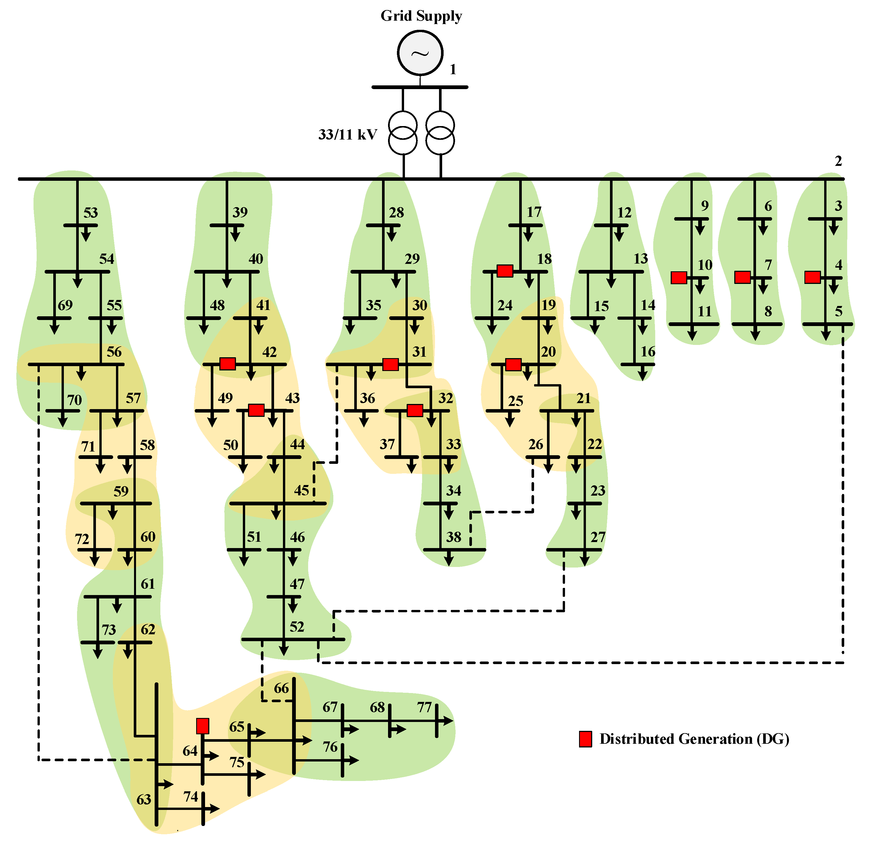
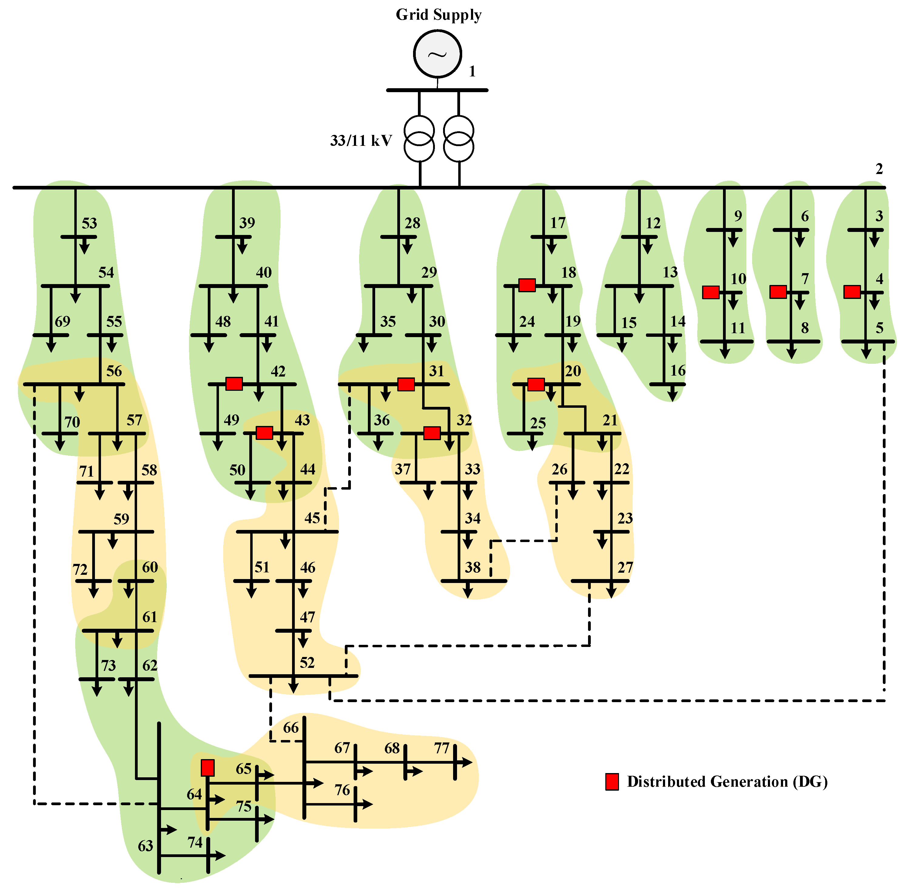
  • Different pre-defined decompositions of the network: Generally, based on the amount of available budget for equipping zones with the local processing units, communication infrastructures, and measurement devices, the number of zones and their sizes (number of internal buses of zones) can be determined in the network. Obviously, the number of zones and their sizes are inversely related to each other, and increasing the number of zones leads to a decrease in their sizes. In this simulation, two predefined network division types are assumed as follow:
    Type 1: According to Figure 5, the network is divided into 18 zones with an average size (number of internal buses) of 6.44 buses.
    Type 2: According to Figure 6, the network is divided into 14 zones with an average size of 7.43 buses.
  • Different operating conditions of the network:
    Network topology (meshed or radial).
    Presence of distributed generations.
  • Different measurement scenarios:
    Case I: Measurement points in the substation and overlapped buses are considered as stated before (in Section 4).
    Case II: Measurement points in Case I plus voltage measurements in the end buses of tie-lines are considered.
To assess the performance of the HDSE method, the estimated voltage profile using the proposed method is compared with the results of local SE (LSE), integrated SE (ISE), and two famous methods in the literature for the coordination phase (Method 1 and Method 2). All comparisons have been made on the same PC (4 core Intel Core i7-4700HQ processor running at 2.4 GHz with 8 GB of RAM) with MATLAB R2018b installed.

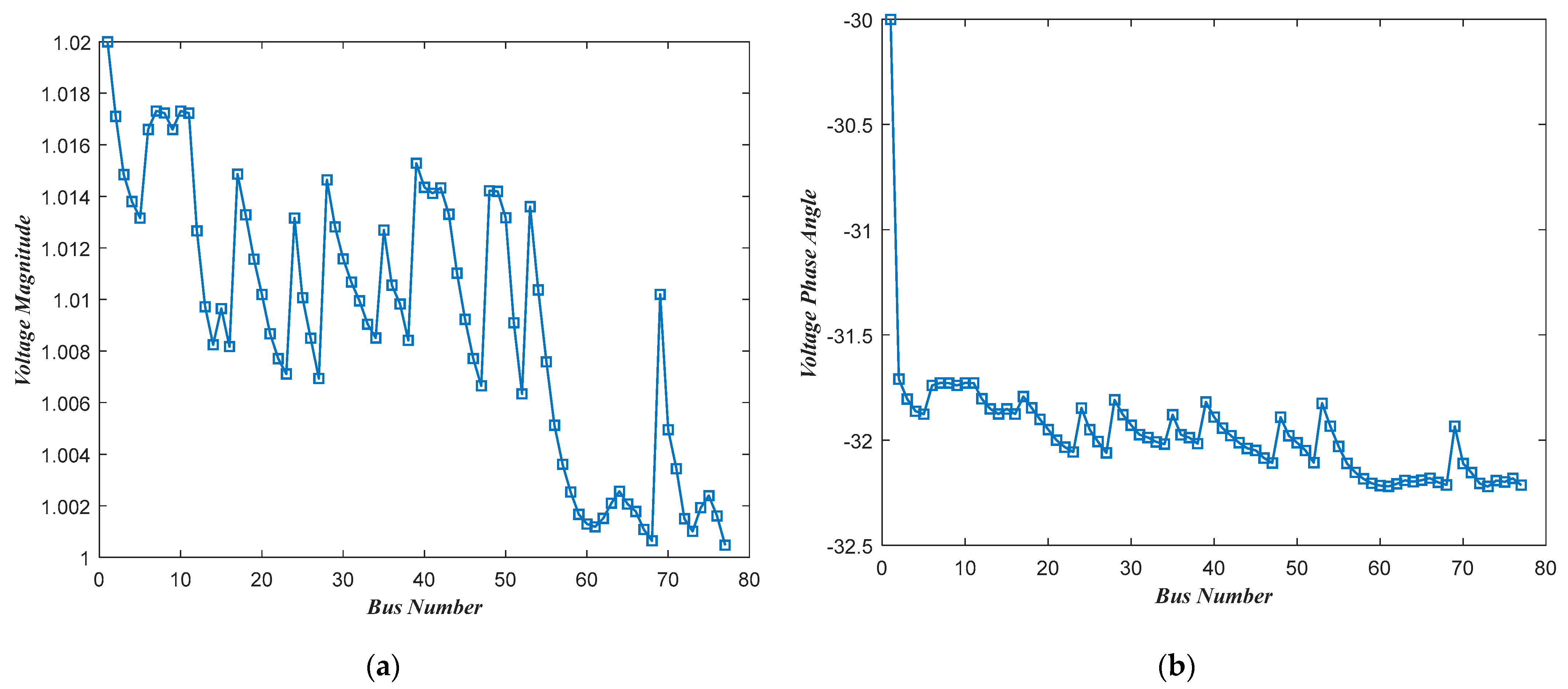
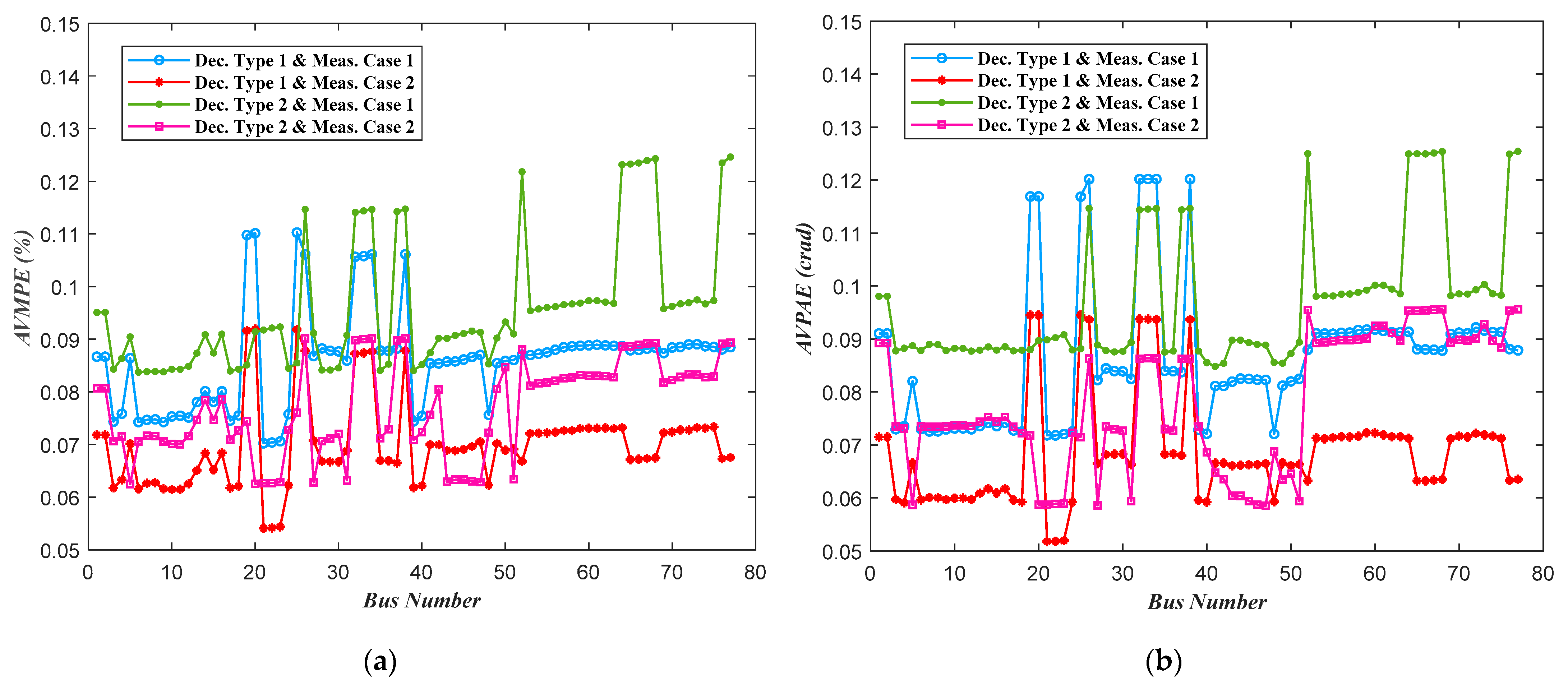
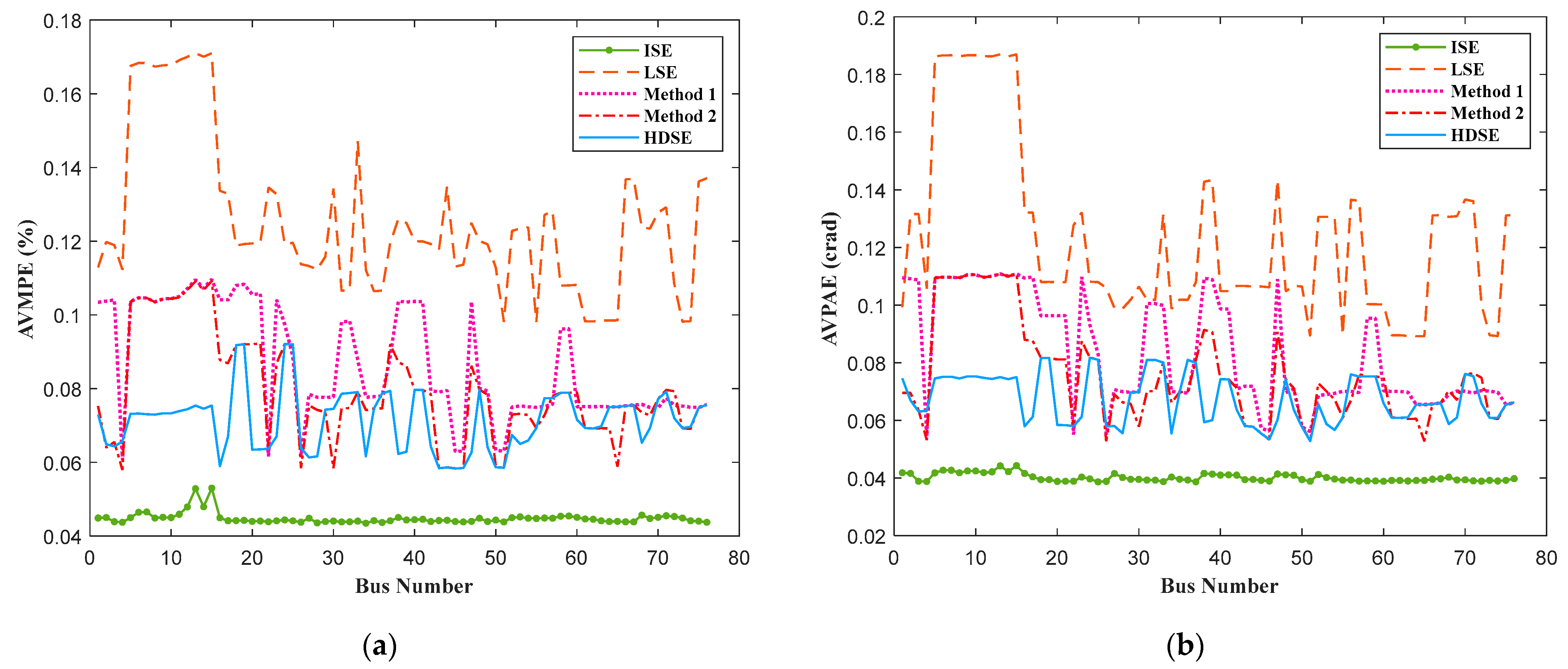
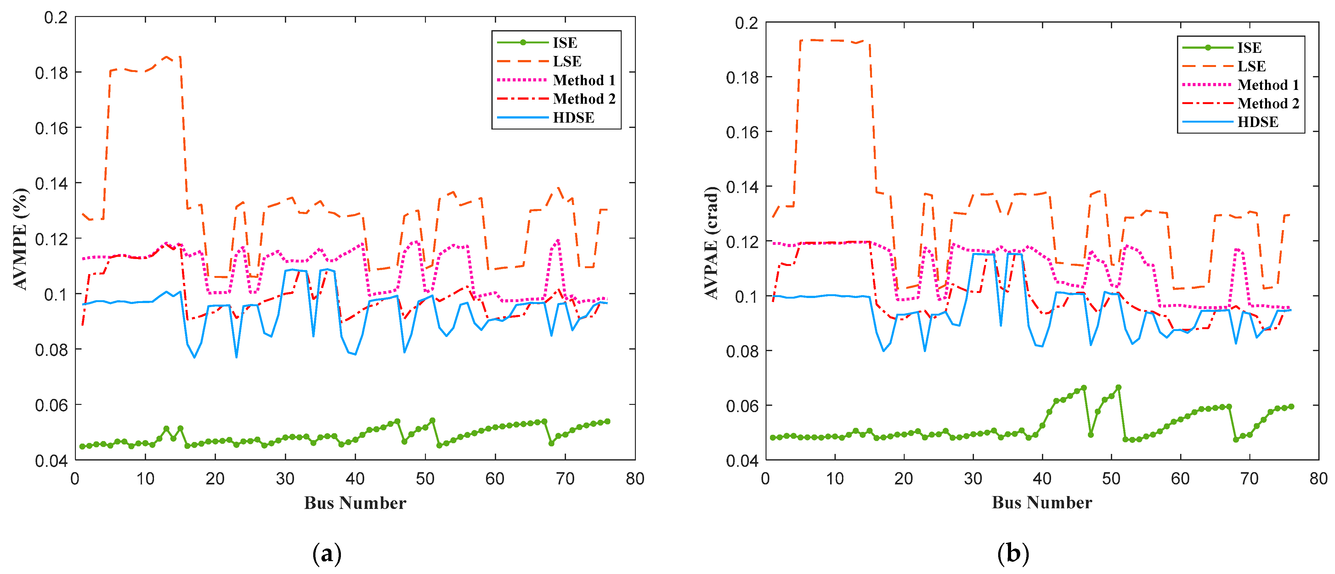
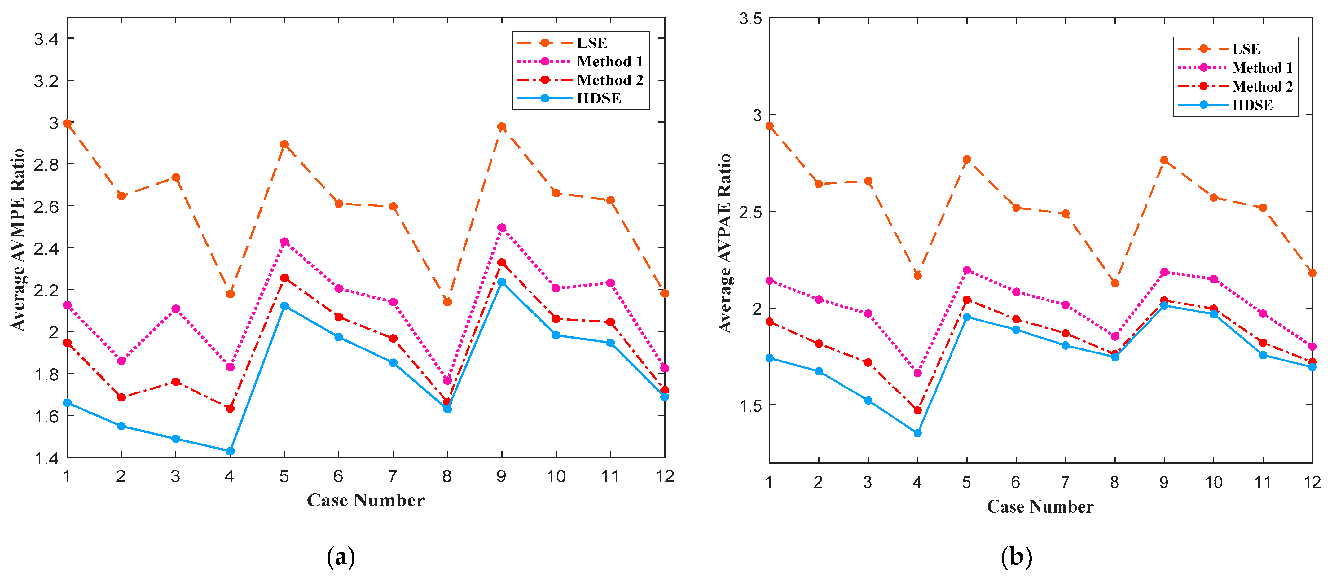
4.1. Accuracy of the Proposed HDSE

To evaluate the estimation accuracy of the proposed HDSE method, as the first step, the average voltage magnitude percentage errors (AVMPE) and average voltage phase angle absolute errors (AVPAE) in all network buses are assessed according to the Monte Carlo simulation approach. For calculating these errors, the power flow results of the test case, i.e., voltage magnitudes and phase angles of all buses, are considered as the true values. The power flow results of the test case with the meshed topology are represented in Figure 7. In addition, the calculated AVMPE and AVPAE values for different measurement scenarios and network decomposition types are presented in Figure 8.
As can be seen in Figure 8, for the SE results related to the same decomposition type, the Case 2 measurement scenario leads to the lower AVMPE and AVPAE values in comparison with Case 1. Given that there are more measurement elements in the Case 2 measurement scenario, this result will be predictable. Moreover, for the SE results relating to the same measurement scenario, due to the direct relationship between the number of zones and the total number of overlapped buses equipped with PMUs in the network, it is expected that considering the type 1 network decomposition method leads to lower estimation error values. According to Figure 8, this superiority exists for most buses of the network with the type 1 decomposition method.
To compare the accuracy of the proposed HDSE method with other decentralized SE procedures in the literature, the AVMPE and AVPAE values for all buses of the network are assessed based on the obtained results from different decentralized SE methods. The values of these errors for two combinations of different network topologies and decomposition methods are represented in Figure 9 and Figure 10.
As can be seen, ISE and LSE methods, respectively, have the lowest and maximum error in both amplitude and phase angle of bus voltages. Indeed, due to the simultaneous processing of all network measured values, the centralized SE method estimates the state of the network more accurately. Additionally, due to the absence of coordination phase in the local SE process, the LSE method has the lowest accuracy among others. Additionally, as expected, on average, Method 1 has less accuracy in coordinating the local SE results between the decentralized implementation approaches of SE.
Besides, as shown in Figure 9 and Figure 10, both of the proposed methods in the literature and the HDSE method have not got any absolute superiority to the others in magnitude and phase angle estimation. However, according to the results, in the case with meshed topology and type 1 decomposition method, the proposed method (HDSE) has better accuracy in comparison with traditional methods, respectively, in 69.5% and 65.8% of the network buses voltage magnitude and phase angle estimation. Additionally, in this case, the average AVMPE and AVPAE of all network buses are 0.0713% and 0.0674 crad for the HDSE method, respectively. These values for Method 1 and Method 2 are 0.0868% and 0.0835 crad and 0.0793% and 0.0757 crad, respectively.
In the case with radial topology and type 2 network splitting approach, in 55.2% and 75% of the network buses, the HDSE method has better accuracy in the AVMPE and AVPAE, respectively. In addition, the average AVMPE and AVPAE for the HDSE approach are 0.0940% and 0.0950 crad, respectively. These values for Method 1 and Method 2 are 0.1084% and 0.1094 crad and 0.0994% and 0.1003 crad, respectively. It should be noted that by eliminating tie-lines and their power flow measurements in radial topology, the average values of AVMPE and AVPAE in meshed topology are lower than those associated with radial topology.
Accuracies of different approaches are also compared in different scenarios including various combinations of network operating conditions, network decomposition method, and measured points according to Table 1. The accuracy comparison is performed in terms of average AVMPE and average AVPAE of all the network buses, which are normalized with their corresponding values in the ISE method. As shown in Figure 11, the proposed HDSE method is more accurate than other decentralized SE approaches in both voltage magnitude and phase angle estimation.

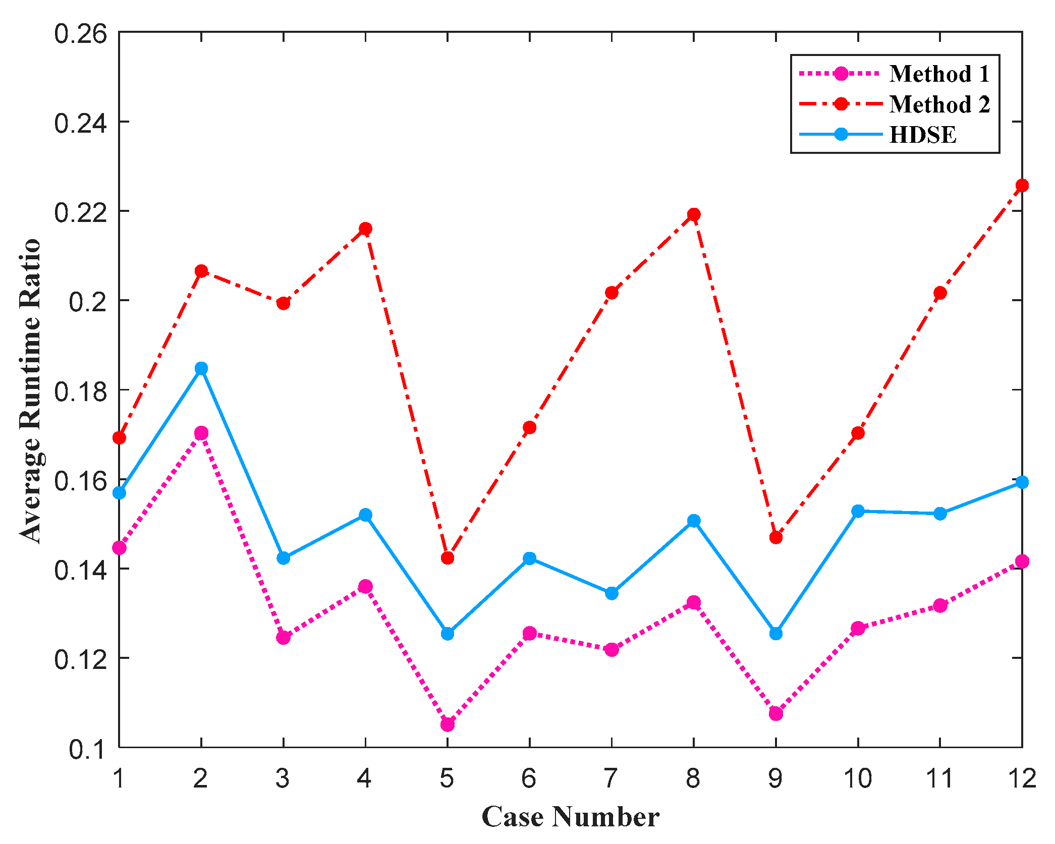
4.2. Runtime of the Proposed HDSE

The other important feature of decentralized SE methods is their abilities in reducing runtime. Therefore, with the following equations, the runtimes of the HDSE (RTHDSE) and traditional methods (RTMethod1 and RTMethod2) are calculated and compared with each other.
R T H D S E = t L S E + max ( t F C , t S C )
R T M e t h o d 1 = t L S E + t C P M 1
R T M e t h o d 2 = t L S E + t C P M 2 ,
where, tLSE, tFC, and tSC are the runtimes of LSE, FCs, and SC, respectively. Moreover, tCPM1 and tCPM2 are the runtimes of the coordination phase in Method 1 and Method 2, respectively.
In Figure 12, the average runtimes of the HDSE and traditional methods, which are normalized with respect to the average runtime of the integrated approach, have been presented.
As can be seen, Method 1 has the lowest average normalized runtime in comparison with Method 2 and the HDSE method in all cases which roots from the straightforward coordination phase applied in Method 1. Besides, in all cases, the proposed HDSE method has better performance in terms of runtime compared to Method 2. Indeed, due to utilizing the distributed processing in the coordination phase of Method 2, the number of considered buses in the SE process of zones with the substation bus or buses which are connected to the neighboring feeders/substations is increased. Owing to this reason, in cases, which a high number of main feeders (like simulated test case) or a high number of tie-lines exist in the network, the runtime of distributed SE approaches will be higher than the proposed HDSE.
Based on the results in the simulated scenarios, Method 1, the HDSE and Method 2 reduce the runtime of the centralized SE by an average of 87%, 85%, and 81%, respectively.

5. Discussion

According to the simulation results, the proposed HDSE method has an appropriate performance in estimating the state of the ADN. As shown in Section 4, the accuracy of the SE results increased with increasing the numbers of measurement elements and network zones. Additionally, based on the accuracy and runtime comparison between different methods of decentralized execution of SE, the proposed method has shown better performance in different operating conditions. Another important point in the performance of the decentralized SE methods is the characteristics of CIs, namely, reliability and latency.
Generally, to estimate the state of the network as best as possible in a decentralized way, all local real-time measured values (for local voltage estimation phase) and all of the required local estimated values in the neighboring zones (for coordination phase) should be transmitted to the related processing unit through communication links (wired or wireless technologies). As previously presented, the latency and reliability of the CIs between sending and receiving units depend on the total number of nodes and the length of communication media that connect them. Therefore, different coordination algorithms applied in the decentralized implementations of the SE process can lead to different overall latencies and reliabilities of CIs.
In the distributed (parallel) SE methods, for coordinating the local SE results of zones, various data from different neighboring zones (which can belong to different feeders or substation) should be transmitted to the database of coordinators. In contrast with the proposed methods in the literature, the coordination phase of the HDSE method is performed using the FCs and SC units. Therefore, all of the local estimated results are first transmitted to the shared database of FCs and SC units in the substation and then the coordination phase is performed. Due to the application of the SE results in other functions of the DMS (like fault management and Volt/Var control), the estimated voltages in all decentralized approaches should be transmitted to the control center. Thus, data transmission from downstream units to upstream units exist in all decentralized SE methods and should not be taken into account in the latency and reliability assessment of the CIs. Therefore, the required data of SC/FCs is easily accessible through the shared database. In this situation, compared with Methods 1 and 2, the CIs in the coordination phase of the proposed HDSE method can be considered as the system with maximum reliability and minimum latency.

6. Conclusions

This paper presents a new hierarchically distributed SE procedure for improving the performance of this important operating study in ADNs. To reach this goal, at first, the network is supposed to be split into some overlapped zones and their local states are calculated by performing parallel SE without any information exchange between neighboring zones. Then, the coordination between obtained local states performs in two different steps utilizing coordinators in the substation and feeders.
To evaluate the performance of the HDSE method, the 77-bus UK generic distribution network is selected as a test ADN and different scenarios were implemented and simulated on this test case. According to the simulated results, it is shown that the proposed HDSE method leads to the SE results with appropriate accuracy. Additionally, in measurement scenarios with a higher number of PMUs (or µPMUs) and decomposition type with a lower size of zones, the accuracy of the SE results was higher than the other scenarios. Besides, based on the comparative study results, the proposed method estimates the network state with more accuracies than the traditional methods (Methods 1 and 2). Moreover, according to the performance analysis, it is shown that the runtime ratio of HDSE to the ISE method was 15% on average. These amounts were 13% and 19% for Method 1 and 2, respectively. Finally, as presented in the discussion section (Section 5), the proposed method improves the characteristics of the CIs, i.e., latency and reliability, in comparison with the distributed SE approaches.

Author Contributions

M.G. developed the model, carried out the simulations, and prepared the original manuscript draft; A.A.T.-F., M.M.-A., M.F.-F., and M.L. reviewed the manuscript and supervised the research. All authors have read and agreed to the published version of the manuscript.

Funding

This research received no external funding.

Institutional Review Board Statement

Not used in our institute.

Informed Consent Statement

Not applicable in this case.

Data Availability Statement

No data reported.

Conflicts of Interest

The authors declare no conflict of interest.

References

  1. Kamrani, F.; Fattaheian-Dehkordi, S.; Gholami, M.; Abbaspour, A.; Fotuhi-Firuzabad, M.; Lehtonen, M. Two-Stage Flexibility-oriented Stochastic Energy Management Strategy for MultiMicrogrids Considering Interaction with Gas-grid. IEEE Trans. Eng. Manag. 2021, unpublished. [Google Scholar]
  2. CIGRE WG C6.11. Development and Operation of Active Distribution Networks; Tech. Rep.; CIGRE: Paris, France, 2011; p. 457. [Google Scholar]
  3. Mladenov, V.; Chobanov, V.; Zafeiropoulos, E.; Vita, V. Characterisation and evaluation of flexibility of electrical power system. In Proceedings of the 10th Electrical Engineering Faculty Conference (BulEF), Sozopol, Bulgaria, 11–14 September 2018. [Google Scholar] [CrossRef]
  4. Vita, V.; Zafiropoulos, E.; Gonos, I.F.; Mladenov, V.; Chobanov, V. Power system studies in the clean energy era: From capacity to flexibility adequacy through research and innovation. In Proceedings of the 21st International Symposium on High Voltage Engineering (ISH 2019), Budapest, Hungary, 26–30 August 2019. [Google Scholar] [CrossRef] [Green Version]
  5. Gholami, M.; Fattaheian-Dehkordi, S.; Mazaheri, H.; Abbaspour-Tehrani-Fard, A. Active Distribution Management System. In Active Electrical Distribution Network: A Smart Approach, 1st ed.; Khan, B., Guerrero, J.M., Padmanaban, S., Alhelou, H.H., Mahela, O.P., Tanwar, S., Eds.; Wiley: Hoboken, NJ, USA, 2021. [Google Scholar]
  6. Dehghanpour, K.; Wang, Z.; Wang, J.; Yuan, Y.; Bu, F. A survey on state estimation techniques and challenges in smart distribution systems. IEEE Trans. Smart Grid 2018, 10, 2312–2322. [Google Scholar] [CrossRef] [Green Version]
  7. Shahidehpour, M.; Wang, Y. Parallel and distributed state estimation. In Communication and Control in Electric Power System; Wiley: Hoboken, NJ, USA, 2003. [Google Scholar] [CrossRef] [Green Version]
  8. Gómez-Expósito, A.; de la Villa Jaén, A.; Gómez-Quiles, C.; Rosseaux, P.; Van Cutsem, T. A taxonomy of multi-area state estimation methods. Electr. Power Syst. Res. 2010, 81, 1060–1069. [Google Scholar] [CrossRef] [Green Version]
  9. Korres, G.N. A distributed multiarea state estimation. IEEE Trans. Power Syst. 2011, 26, 73–84. [Google Scholar] [CrossRef]
  10. Yang, T.; Sun, H.; Bose, A. Transition to a two-level linear state estimator—Part I: Architecture. IEEE Trans. Power Syst. 2011, 26, 46–53. [Google Scholar] [CrossRef]
  11. Yang, T.; Sun, H.; Bose, A. Transition to a two-level linear state estimator—Part II: Algorithm. IEEE Trans. Power Syst. 2011, 26, 54–62. [Google Scholar] [CrossRef]
  12. Gómez-Expósito, A.; de la Villa Jaén, A. Two-level state estimation with local measurement pre-processing. IEEE Trans. Power Syst. 2009, 24, 676–684. [Google Scholar] [CrossRef]
  13. Gómez-Expósito, A.; Abur, A.; de la Villa Jaén, A.; Gómez-Quiles, C. A multilevel state estimation paradigm for smart grids. Proc. IEEE 2011, 99, 952–976. [Google Scholar] [CrossRef]
  14. Nusrat, N.; Irving, M.; Taylor, G. Development of distributed state estimation methods to enable smart distribution management systems. In Proceedings of the 2011 IEEE International Symposium on Industrial Electronics, Gdansk, Poland, 27–30 June 2011; pp. 1691–1696. [Google Scholar] [CrossRef]
  15. Nusrat, N.; Lopatka, P.; Irving, M.R.; Taylor, G.A.; Salvini, S.; Wallom, D.C.H. An overlapping zone-based state estimation method for distribution systems. IEEE Trans. Smart Grid 2015, 6, 2126–2133. [Google Scholar] [CrossRef]
  16. Muscas, C.; Pau, M.; Pegoraro, P.A.; Sulis, S.; Ponci, F.; Monti, A. Multiarea distribution system state estimation. IEEE Trans. Instrum. Meas. 2015, 64, 1140–1148. [Google Scholar] [CrossRef]
  17. Muscas, C.; Pegoraro, P.A.; Sulis, S.; Pau, M.; Ponci, F.; Monti, A. Fast multi-area approach for distribution system state estimation. In Proceedings of the 2016 IEEE International Instrumentation and Measurement Technology Conference, Taipei, Taiwan, 23–26 May 2016; pp. 1–6. [Google Scholar] [CrossRef]
  18. Pau, M.; Ponci, F.; Monti, A.; Sulis, S.; Muscas, C.; Pegoraro, P.A. An efficient and accurate solution for distribution system state estimation with multiarea architecture. IEEE Trans. Instrum. Meas. 2017, 66, 910–919. [Google Scholar] [CrossRef] [Green Version]
  19. IEEE. IEEE Standard for Synchrophasor Measurements for Power Systems, Std. C37.118.1; IEEE: Piscataway, NJ, USA, 2011. [Google Scholar]
  20. IEEE. IEEE Standard for Synchrophasor Data Transfer for Power Systems, Std. C37.117.2; IEEE: Piscataway, NJ, USA, 2011. [Google Scholar]
  21. Abur, A.; Exposito, A.G. Power System State Estimation Theory and Implementation; Marcel Dekker: New York, NY, USA, 2004. [Google Scholar] [CrossRef]
  22. Phadke, A.G.; Thorp, J.S. Synchronized Phasor Measurements and Their Applications; Springer: Berlin/Heidelberg, Germany, 2008. [Google Scholar] [CrossRef]
  23. Gholami, M.; Abaspour-Tehrani-Fard, A.; Moeini-Aghtaie, M. Linear voltage based state estimator for active distribution system including phasor measurement unit (PMU). In Proceedings of the 2018 Electrical Power Distribution Conference (EPDC), Tehran, Iran, 9–10 May 2018. [Google Scholar] [CrossRef]
  24. Gholami, M.; Abaspour, A.; Moeini-Aghtaie, M.; Fotuhi-Firuzabad, M.; Lehtonen, M. Detecting the Location of Short-Circuit Faults in Active Distribution Network Using PMU-Based State Estimation. IEEE Trans. Smart Grid 2020, 11, 1396–1406. [Google Scholar] [CrossRef]
  25. Monticelli, A.; Garcia, A. Reliable bad data processing for real-time state estimation. IEEE Trans. Power Appl. Syst. 1983, 102, 1126–1139. [Google Scholar] [CrossRef]
  26. Magnago, F.H.; Abur, A. A Unified approach to robust meter placement against bad data and branch outages. IEEE Trans. Power Syst. 2000, 15, 945–949. [Google Scholar] [CrossRef]
  27. Gholami, M.; Abbaspour, A.; Fattaheian-Dehkordi, S.; Lehtonen, M.; Moeini-Aghtaie, M.; Fotuhi, M. Optimal allocation of PMUs in active distribution network considering reliability of state estimation results. IET Gener. Transm. Distrib. 2020, 14, 3641–3651. [Google Scholar] [CrossRef]
  28. Zhao, L.; Abur, A. Multi area State Estimation Using Synchronized Phasor Measurements. IEEE Trans. Power Syst. 2005, 20, 611–617. [Google Scholar] [CrossRef]
  29. Conejo, A.J.; de la Torre, S.; Canas, M. An Optimization Approach to Multiarea State Estimation. IEEE Trans. Power Syst. 2007, 22, 213–221. [Google Scholar] [CrossRef]
  30. DTI Centre for Distributed Generation and Sustainable Electrical Energy, United Kingdom Generic Distribution System, Generic HV Underground Network. Available online: http://monaco.eee.strath.ac.uk/ukgds/UnitedKingdomGenericDistributionNetwork(UKGDS) (accessed on 28 March 2015).
  31. Liu, J.; Tang, J.; Ponci, F.; Monti, A.; Muscas, C.; Pegoraro, P.A. Trade-offs in PMU deployment for state estimation in active distribution grids. IEEE Trans. Smart Grid 2012, 3, 915–924. [Google Scholar] [CrossRef]
  32. Dugan, R.C. The Open Distribution System SimulatorTM (OpenDSS); Electric Power Research Institute: Washington, DC, USA, 2013. [Google Scholar]
Figure 1. Shared elements between neighboring zones and their separation method to perform independent local SEs: (a) level of zone overlapping between neighboring zones, (b) boundary of Zone 1 and (c) boundary of Zone 2.
Energies 14 01772 g001
Figure 2. Proposed hierarchically distributed architecture of the state estimation process.
Energies 14 01772 g002
Figure 3. Sub-networks of feeder coordinators (FCs) and substation coordinator (SC) in a typical active distribution network (ADN).
Energies 14 01772 g003
Figure 4. Flowchart of the coordination phase in the proposed Hierarchically Distributed state estimation (HDSE) procedure.
Energies 14 01772 g004
Figure 5. Decomposition of the UK 77-bus distribution network (type 1).
Energies 14 01772 g005
Figure 6. Decomposition of the UK 77-bus distribution network (type 2).
Energies 14 01772 g006
Figure 7. Power flow results of the test case with meshed topology: (a) voltage magnitude and (b) voltage phase angle.
Energies 14 01772 g007
Figure 8. Estimation errors of the HDSE method for the test network with meshed topology: (a) average voltage magnitude percentage errors (AVMPE) and (b) average voltage phase angle absolute errors (AVPAE).
Energies 14 01772 g008
Figure 9. Evaluated errors in the test network with meshed topology, case 2 measurement scenario and type 1 decomposition method: (a) AVMPE and (b) AVPAE.
Energies 14 01772 g009
Figure 10. Evaluated errors in the test network with radial topology, case 2 measurement scenario and type 2 decomposition method: (a) AVMPE and (b) AVPAE.
Energies 14 01772 g010
Figure 11. Error comparison for different decentralized SE methods in different scenarios described in Table 1: (a) normalized average AVMPE and (b) normalized average AVPAE.
Energies 14 01772 g011
Figure 12. Comparison of normalized runtimes for different decentralized SE methods in different scenarios.
Energies 14 01772 g012
Table 1. Information related to the considered scenarios.
CaseNetwork TopologyDG Grid ConnectionNetwork Decomp. TypeMeas. Scenario
1Mesh12
2Mesh11
3Mesh22
4Mesh21
5Radial12
6Radial11
7Radial22
8Radial21
9Radial🗶12
10Radial🗶11
11Radial🗶22
12Radial🗶21
Publisher’s Note: MDPI stays neutral with regard to jurisdictional claims in published maps and institutional affiliations.

