1. Introduction
The development of the underground coal mining industry is boosted by the need to improve the efficiency of the mining process, at the same time, maintaining the required level of safety and protecting the environment. Machines and devices with innovative designs that automate the process of mining are the key elements required to improve the mining process. One of the basic directions of development in the world mining industry is the automation of a longwall unit. Today, manufactured longwall shearers have improved mining efficiency with a face feed speed of almost 10 m/min. This means that the sections of the powered roof support must be moved within a maximum of 9 s for sections that are 1.5 m wide, and 10.5 s for sections with a width of 1.75 m. It is not possible to obtain such performance parameters using traditional, manual control of the powered roof support. These requirements and the fact that the design of a support section is complex means that a hydraulic system needs partial or full automation to achieve large hydraulic fluid flows [
1,
2,
3,
4,
5,
6]. The automation process reduces the total number of operators controlling the support sections and makes it possible to remove them from the immediate vicinity of the support that is being moved. This has a positive effect on safety by removing personnel from the active face.
The procedure developed based on research and analysis includes four stages. These are essential for manufacturers of longwall roof supports and producers of control systems, as it accurately and easily shows what the sequence of design, research, and production work should be. From a scientific point of view, the third stage is the most important one, as the results obtained, either positive or negative, make it possible to analyse whether the assumptions made in Stage 1 coincide with the design made in Stage 2. As a result of the research on prototypes and the acceptance of prototype modifications, documentation is developed, as presented in Stage 4. The procedure takes into account all possible safety requirements and the possibility of effective preparation of automatic control. The nature of the presented concept is open, as it takes into account the possibility of introducing specific conditions in which the seam will be mined, and the selection system used. The procedure can be modified to fit the research and development of automatic control devices and future requirements.
The depth of underground hard coal mining has been constantly increasing in the past years. This, in turn, increases natural hazards such as exogenous fire, seismicity, and methane hazards [
7,
8]. The longwall system in terms of these hazards challenges manufacturers, researchers, and mining companies to ensure an appropriate level of occupational safety. Currently, a considerable involvement of researchers in solving problems related to methane hazards [
8,
9,
10,
11,
12,
13,
14,
15], endogenous fires [
7], and seismicity [
16] can be observed worldwide. Therefore, global coal mining is at the forefront of the desired energy resource alongside oil and gas [
17,
18,
19]. Coal mining in an underground mine is carried out using a longwall system that uses such machines as a shearer that mines the coal, a scraper conveyor for haulage, and a powered roof support for the longwall system. They operate together and form a longwall complex (
Figure 1).
Monitoring the machinery and equipment in the longwall complex and mining and geological conditions largely contributes to the maintenance of sustainable development of mining in the world and improvement of work safety [
20,
21,
22,
23,
24,
25,
26,
27,
28]. Recently, there has been extensive activity in the development of research on the application of new technologies in mining thanks to Industry 4.0 [
29,
30,
31,
32]. The selection of technical parameters of machines and equipment is important due to the arduous conditions in which they will work. It is possible to evaluate correctly selected machines through active monitoring of their operating parameters and analysis of operating conditions [
33,
34,
35,
36,
37,
38,
39]. One of the main sources of hazards causing accidents at work in mining plants is the technical infrastructure and, in particular, machinery and technical equipment. In 2019, the rate of accident and mortality associated with technical hazards caused by machines and equipment was approximately 50% of all events [
40]. To ensure safe use and proper hazard assessment, machine and control equipment designers place the greatest emphasis on structural safety aspects. The related requirements are defined in standards [
41,
42,
43,
44,
45,
46] harmonised with the Machinery Directive [
47]. However, due to technical progress, such standards do not exist for most of the machine control systems currently developed. Therefore, in order to ensure compliance with the essential requirements of the Directive, a package of technical standards on functional safety issues was created; it includes the concept of safety assessment of machinery [
41,
43].
The mining and geological conditions in which the powered roof support system is to be used can be divided into dynamic impacts of the rock mass on the longwall excavation where the roof support system works. This phenomenon is more dangerous than mining and geological conditions in which the rock mass does not tend to tremble. Sudden clamping of the excavation means a static displacement that overloads the longwall complex that is supposed to be supported by the powered roof support. The load that impacts powered roof supports results from the movement of rock masses at a certain speed. The main task of powered longwall supports is to transfer loads resulting from changing mining and geological conditions, allowing for deformation of the longwall excavation to a minimum degree [
48].
The powered roof support is a hydraulic machine powered by high pressure with an oil–water concentrate as an energy carrier. Spragging of the support section of the powered support for the required height of the excavation and its support is conducted by hydraulic legs. They constitute a structural connection between the canopy and floor base. As a result of the impact of the rock mass, the hydraulic legs carry the load depending on the conditions under which the powered support operates. Their protection is ensured by placing a safety valve in the hydraulic system [
49]. It is vital to carry out an economic analysis of the effective protection of the powered roof support together with all machines of the longwall complex. In the past, several studies on the automation of the entire mining process were conducted [
50,
51,
52,
53,
54]. The selection of a safety valve for the hydraulic system of the leg of the powered roof support working in the conditions where tremors often occur is key as it affects the safety of machines and people [
55,
56].
2. Materials and Methods
Coal mining in an underground mine is based on a longwall complex that uses the powered roof support. In most cases, a hydraulic system based on manual controls is used to control the roof support. This is mainly determined by the economic efficiency of the company. It is reasonable to work towards reducing the number of workers near working machines to improve work safety. It is also important to measure the number of failures of machines and equipment carrying out technological processes related to hard coal mining.
The development of longwall complex automation technology in recent years has been directed towards the identification of shearer operation parameters based on the monitoring. A device that plays a crucial role here is a sensor that is applied in various systems designed to monitor the parameters of a longwall complex [
57,
58,
59]. It is intended to improve occupational safety. With the development of intelligent computing technologies, it has become possible to develop intelligent algorithms related to neural networks, fuzzy logic, hybrid methods [
58,
59,
60,
61,
62,
63,
64,
65,
66,
67,
68,
69,
70,
71,
72,
73,
74,
75,
76,
77]. This formed the foundation for the development of an automatic control system for a powered roof support in a longwall complex.
2.1. System Design and Development
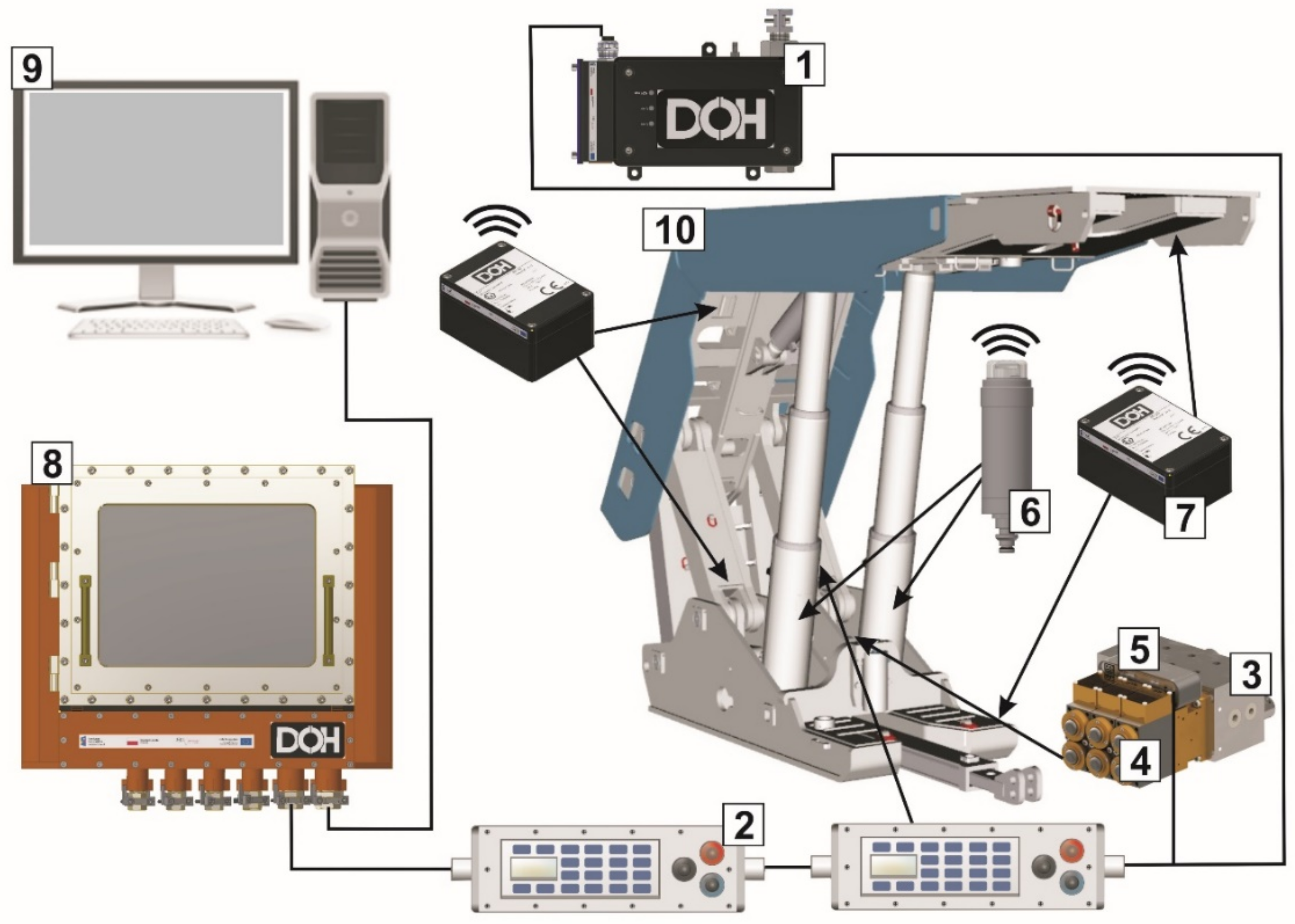
The powered roof support section, with hydraulic legs as its main elements, directly affects the required protection of the excavation. Vital functions are performed by other hydraulic cylinders including advancint the armoured face conveyor and in the powered roof support, such as the conveyor slide or the support of the canopy. Monitoring the pressure in the legs and determining the geometry of the section position in the excavation is an essential factor in the exploitation of longwall complexes. The possibility of automating specific sequences of work of particular elements of the support and controlling their implementation allows limiting the presence of the miners in the excavation. Equally important is the fact that the section of the roof support is guided by the profile of the excavation by means of appropriate cooperation of the section of the roof support with a scraper conveyor. Based on the presented concept, a vision of the system was designed together with a visualisation of the operating parameters, which is shown in
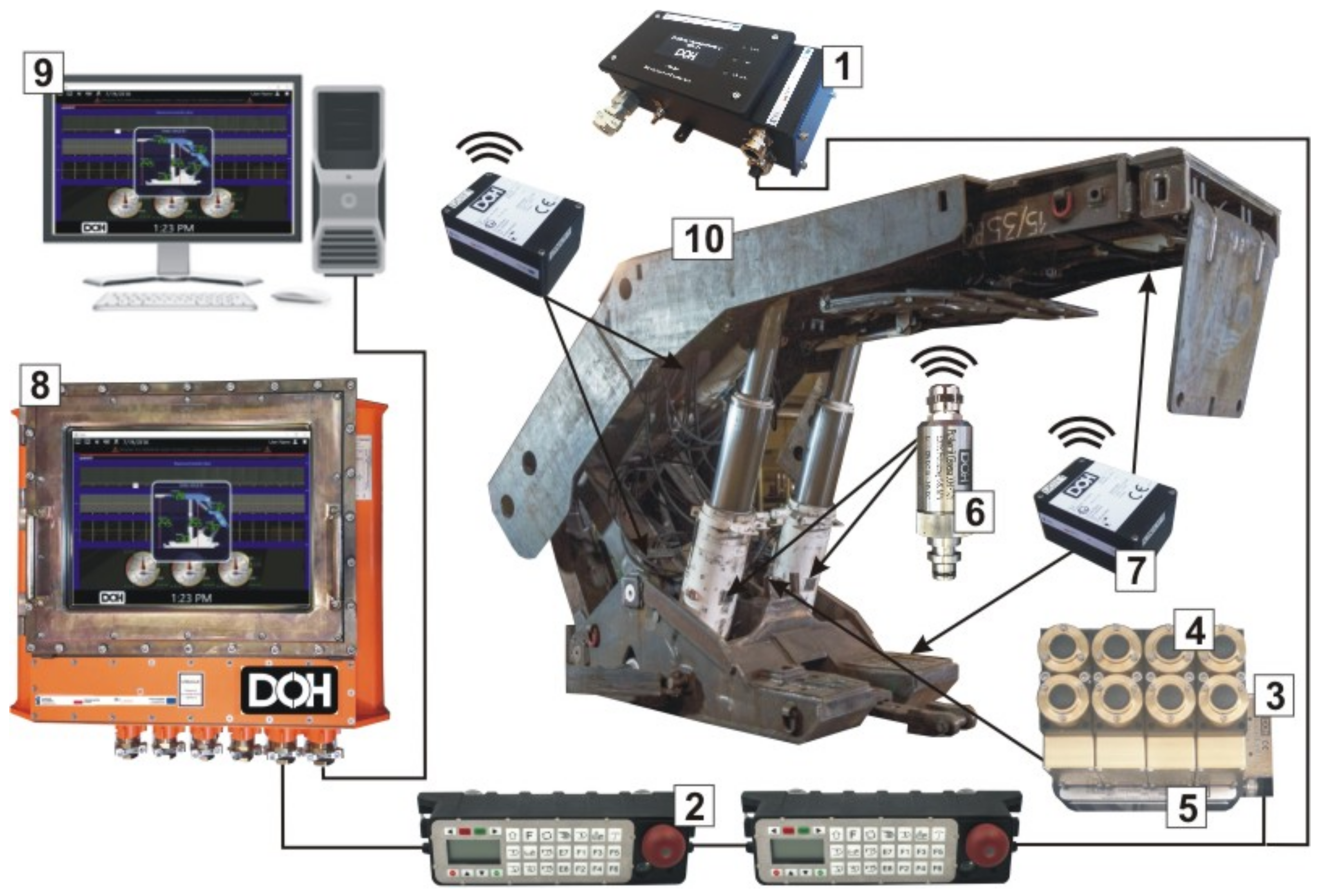
Figure 2. A diagram of the actual control system of the powered system as a test demonstrator is shown in
Figure 3.
2.2. The Requirements for the Design Procedure
The concept of the software and database structure was based on the assumptions of the analysis of the control system operation possibilities. A special criterion is to determine the areas which will constitute a visualisation of the working parameters. The information gathered in the database will be used to report on the production process of coal mining. The concept for the development of computer software architecture is based on the research and operating experience of the authors. Based on the theoretical analyses made, the assumptions of software architecture modules and databases were developed. Due to the gaps and limitations caused by the computing power of a computer operating in an underground mine, the focus was put on collecting relevant information such as pressure measurement in powered roof supports and their position geometry. One of the elements of creating a database is to test whether the proposed structure and data resource correspond to the requirements set at the design stage. The designed software architecture together with the database will constitute the information base of the control system.
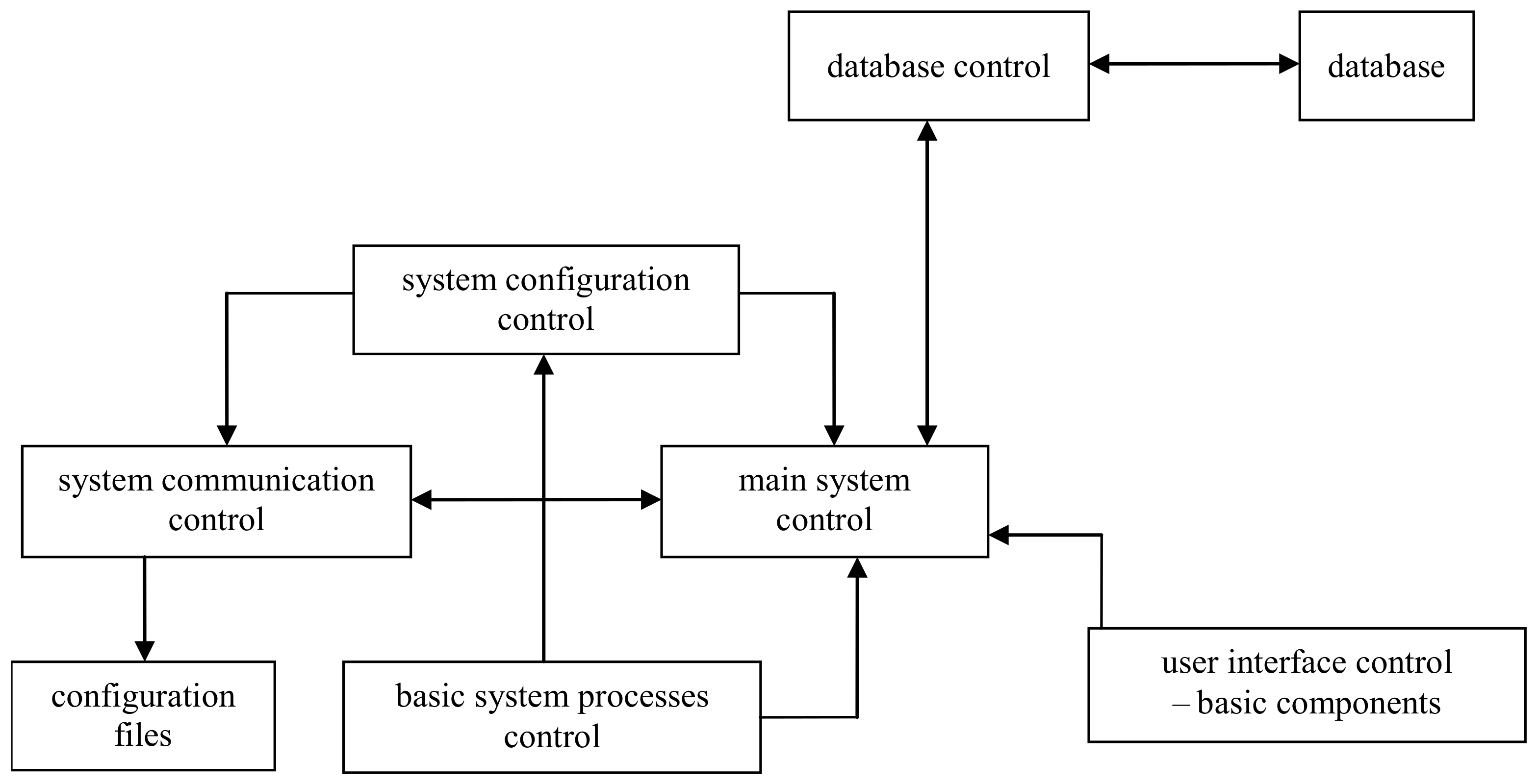
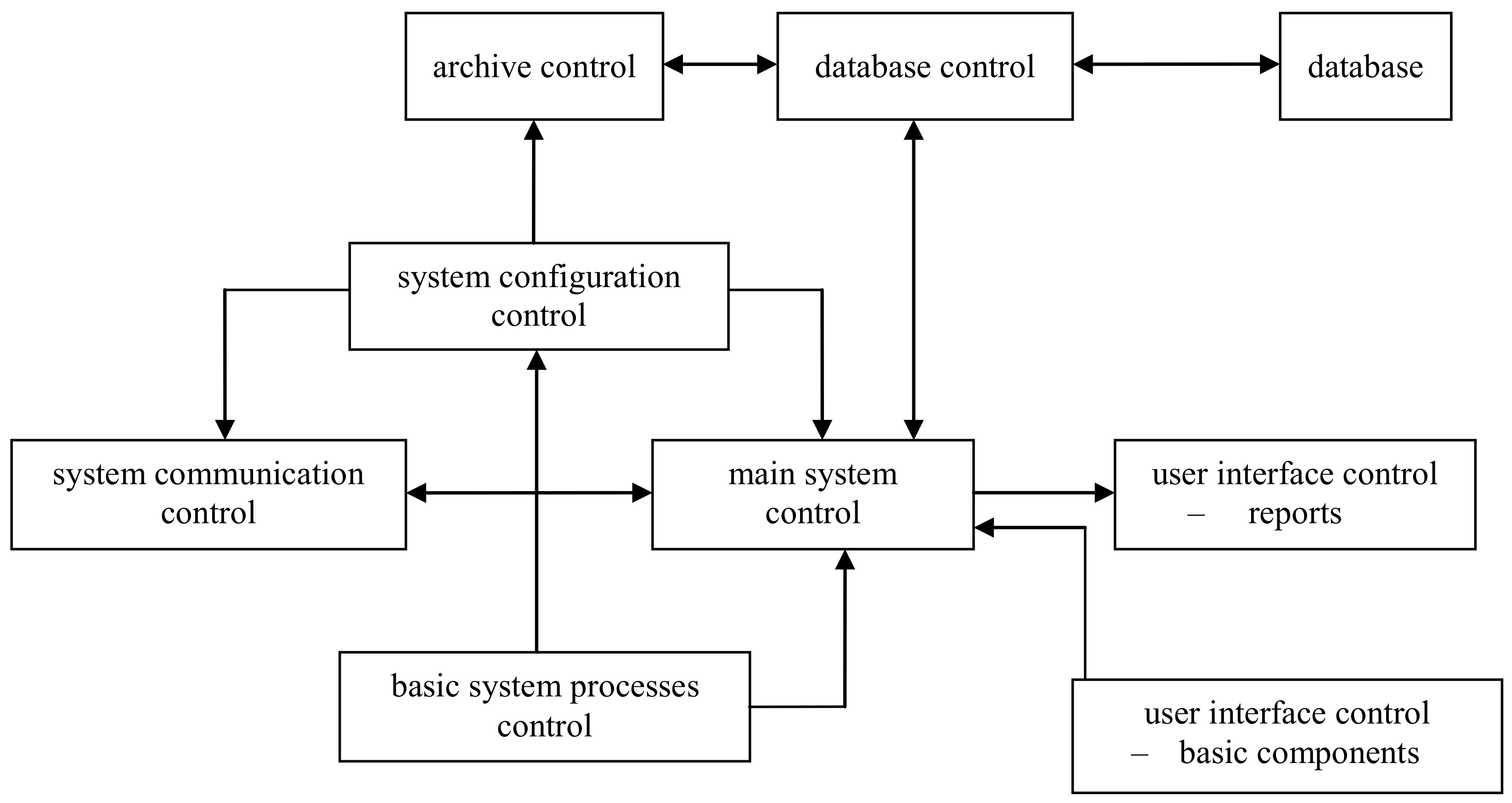
The architecture diagram for the software for the computer that will operate on the surface and one that will operate underground are shown in
Figure 4 and
Figure 5.
3. The Concept of Safety and Hazard Assessment
The electro-hydraulic system designed to control the powered roof support should perform its intended control functions even under damage or disturbance conditions in a predictable manner and with specified reliability. Measures taken to minimise the likelihood of such damage or disturbances and their extent depends on the level of hazard associated with the specific control function.
Research on the evaluation of the reliability of the implemented safety function for the electro-hydraulic control system of the powered roof support is aimed at reducing the risk of hazardous events to an acceptable level. The hazard reduction can be carried out based on standards [
41,
42,
43,
44,
45,
46], to optimally achieve the protection of the system. In the process of designing and constructing the control system, the risks were analysed, and measures were taken to protect the operator from the existing hazards. The hazard assessment is the result of logical steps, allowing for systematic analysis. The system or the machine must be designed and constructed taking into account the results of the hazard assessment. The first step of the assessment is to identify system components (equipment) and later the sources of the hazard for all activities of the operation. The authors considered only those risk factors that have a fundamental impact on the assessment of the effects of a threat when estimating the hazard [
20]. Four levels of hazard were adopted for research based on own experience.
- (1)
Unacceptable—hazard reduction is necessary, otherwise, the system cannot be authorised;
- (2)
Undesirable—hazard is only acceptable if the expenditure involved in reducing it is clearly higher than the effects achieved or if hazard reduction is not achievable;
- (3)
Acceptable—the hazard is only acceptable if the expenditure involved in reducing it is significantly higher than the effects achieved;
- (4)
Negligible—further investment in hazard reduction is not acceptable.
An individual assessment based on good practice and experience was adopted for the risk assessment. This method uses predefined value ranges and descriptive measures such as:
S1—negligible (the risk is very rare, the chance of an event occurring is low, a probability of no more than 10%),
S2—minor (light injuries, mild occupational disease, 11–30% probability),
S3—serious (serious injury to one or more persons or death of one person, probability 31–60%),
S4—severe (many people die, probability 61–80%),
S5—catastrophic (very many deaths and practically total destruction of the system, a probability above 81%).
In general, it must be assumed that the hazard is a combination of the intensity of the occurrence of safety
h and its consequences
S:
The total hazard associated with the use of the system consists of several hazards and therefore, the total hazard can be assumed as follows:
where
hi—the intensity of the
i-th hazard and
Si—the consequences of the
i-th hazard.
The probability of the
i-th hazard can be determined.
Expected impact per unit of time:
Additionally, as a result
The result of the assessment is presented in
Table 1.
The parameter determining the level of hazard is primarily the severity of the damage that may occur as a result of failure to perform the safety function once it has been recalled. The consequences of failure to perform the exemplary control functions of the electro-hydraulic powered roof support are almost always serious for the health and life of those operating the machine and those around it. The analysis of the required performance level (PL) is based on the identification of the tolerable hazard function [
45].
When defining the level of safety assurance PL, we refer to it as the ability to perform safety functions under the expected conditions. There are five discreet levels of safety assurance marked as:
a—indicates the lowest probability of failure,
b—means the average probability of damage,
c—means a good probability of damage,
d—means a high probability of damage,
e—means the highest probability of damage.
Determination of the Safety Integrity Level (SIL) is based on the estimation of the value of hazard and the ability of the control system to reduce hazards [
41]. As already mentioned above, the safety function can be set up in two different ways. The determined safety level of SIL and PL for the tested control system was also compared based on the probability of accidental equipment failure.
Table 1 presents the results of the analysis of the safety function.
Table 1 presents how to assesses the hazard and its reduction and determines the Safety Performance Level PL and the Safety Integrity Level SIL. In the analysis of a given safety function, PL and SIL2 levels were obtained, and the estimated hazard is assumed at S
2. The analysed electro-hydraulic control system performing the safety function is characterised by a safety level not worse than that required.
Research on the Development of the Electro-Hydraulic Control System
The control system together with the mechanical and hydraulic system is crucial and often determines the efficiency of the roof support. Therefore, it is well justified that scientific activity regarding the control system should be boosted. The search for a system that would allow for automatic operation without the need to position workers in the longwall is intensifying. The use of digital data—both for the roof support and the whole complex—shows that the demand for smart control has been continuously increasing.
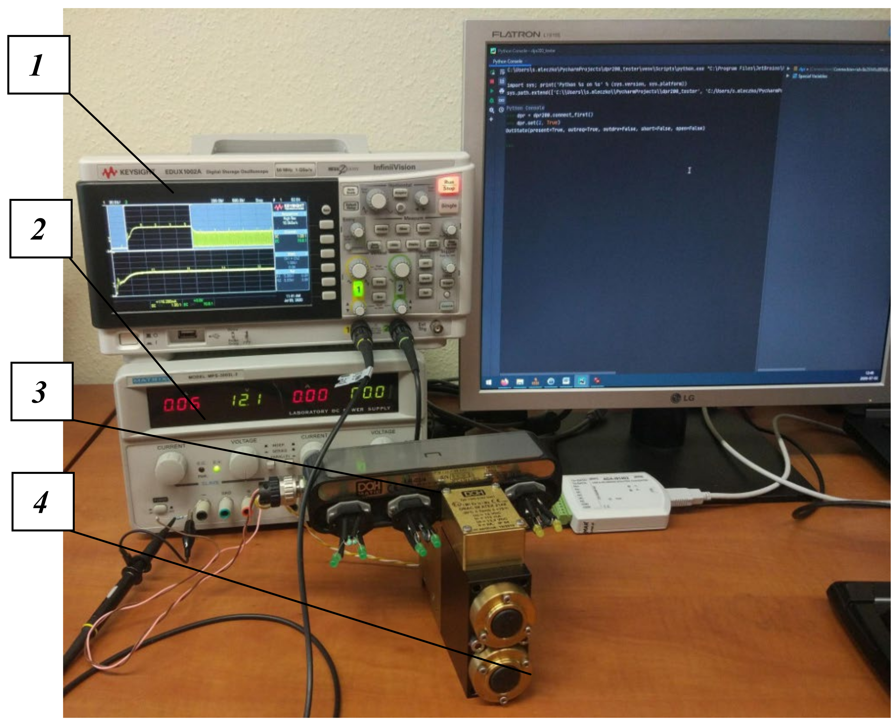
Currently, it is not possible to eliminate the miners from the longwall. This is also not to be expected in the coming years. The main reason is that there are no measures that would precisely specify the mining and geological conditions of each longwall. However, this does not limit the development of control systems, for which the requirements are increasing and will grow. The objective is to focus on works outside the mining area as much as possible. Here, the control systems are fundamental. Research in this area mainly includes work on the development of an electro-hydraulic control system. A testing station was designed with a virtual controller built in. The station is used to define the number of control system parameters (
Figure 6).
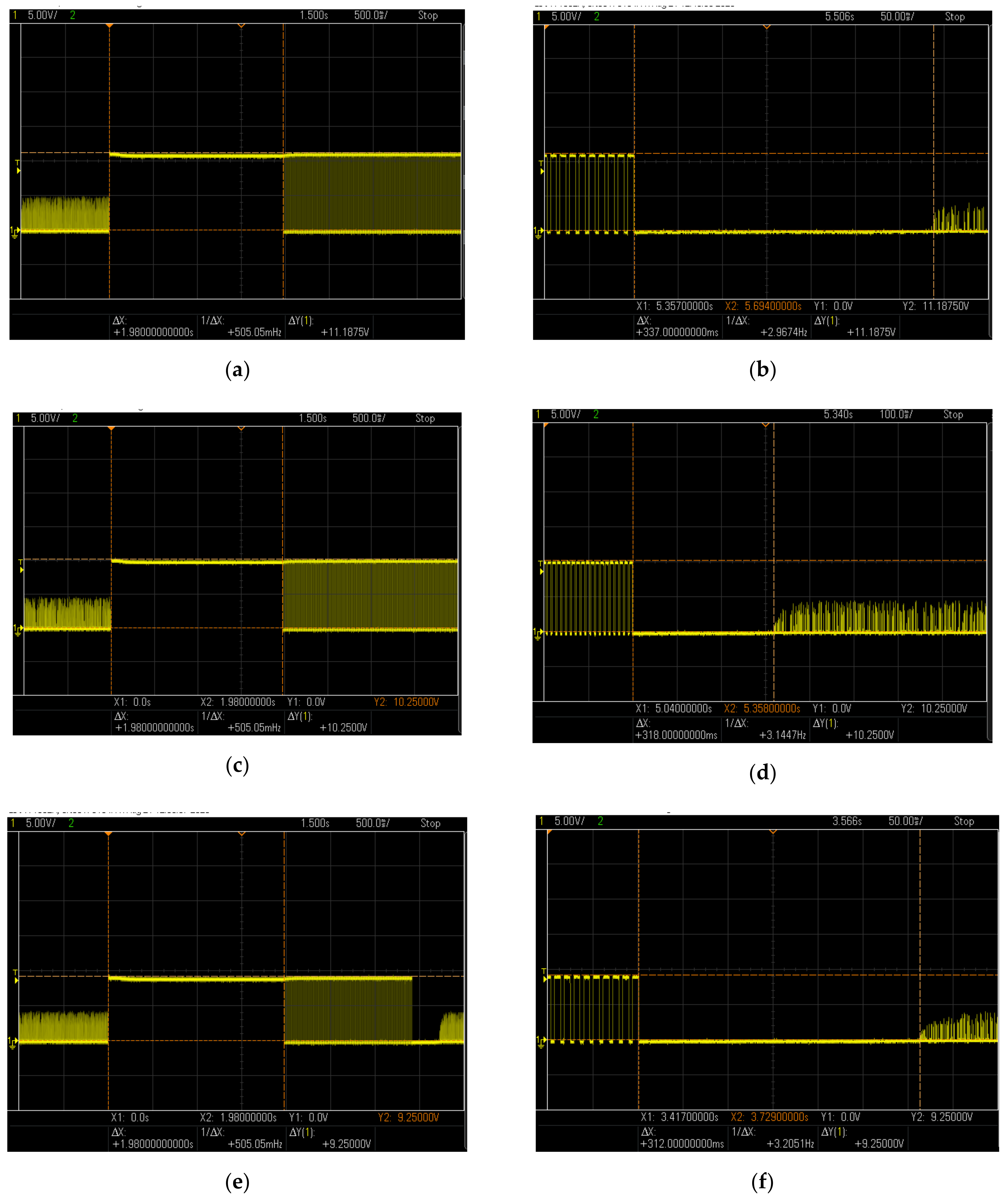
The monitoring scope of the system is wide. It was used to determine the times for implementing the basic functions of the support such as the spreading and withdrawing of sections (extensions/slides of hydraulic legs mounted between floor bases and canopies). It measured the times of switching on the PWM signal and full signal supply for the basic functions of the powered roof support. The operating parameters of the control system obtained for individual phases of the section operation are shown in
Figure 7.
The obtained results clearly indicate that the tested electro-hydraulic system has very low response times. This provides fast and reliable performance of the roof support. Such parameters make it possible to prepare both a comparative and sensitivity analysis of the control system and its components. Next, the results are used to adapt the control parameters to the mining and geological conditions of an individual longwall. It can, therefore, be assumed that virtual testing techniques applied for the systems that are already in use, new ones, or even prototypes can potentially facilitate their improvement. At the same time, the conditions to which these systems will be subject in real conditions are impossible to achieve in laboratory conditions.
4. The Concept of Developing a Procedure as a Basis for the Introduction of an Automatic Control System
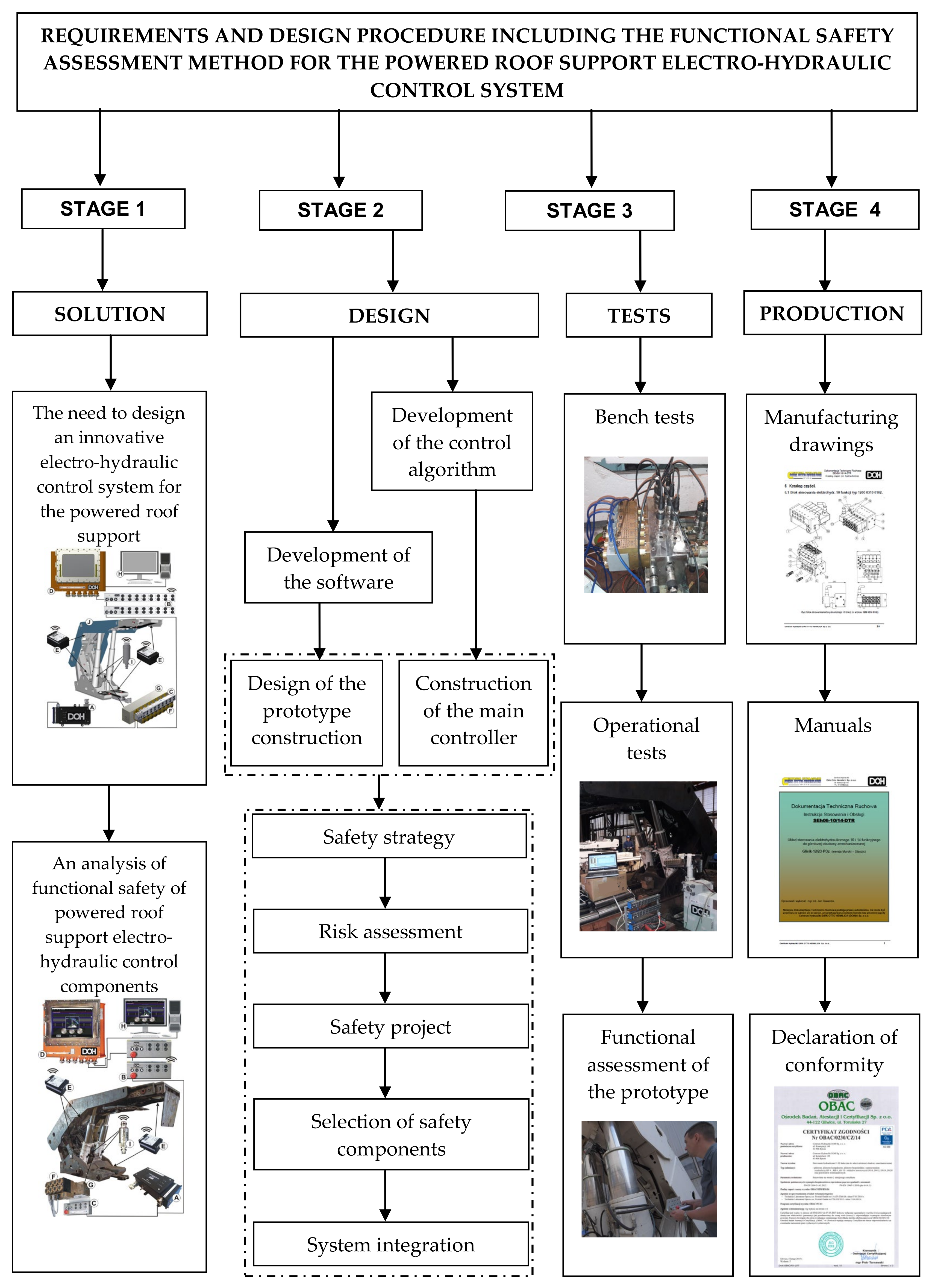
The development of a comprehensive design procedure, together with the procedure for conducting tests and the required safety assessment, is important in terms of adapting the system to the roof support structure and the conditions under which the system will operate. The procedure in
Figure 8 includes four stages. The results should be used by manufacturers of roof supports and control systems, as it presents the order of design, research, and production. The third stage, from a scientific point of view, is the most important one, as the positive or negative results obtained make it possible to analyse whether the assumptions made in Stage 1 coincide with the design in Stage 2. As a result of research into prototypes and the acceptance of prototype amendments. The production documentation is then developed as outlined in Step 4. The authors of the study included all possible points for safety and efficient use.
Analysis of the electro-hydraulic control system together with the visualisation of the operation parameters of the powered roof support in the conditions of adverse effects of the rock mass shows that the construction of the powered roof support must be adapted properly. It is important to prepare the structure of the roof support so the control system and the sensors can be mounted properly to achieve the right operating parameters and ensure the necessary safety level. The highest level of functional safety for the components comprising the control and visualisation system requires the use of all testing methods. In particular, this concerns the safety of the miners.
Identification of potential hazards associated with the emergence of hazards resulting from the operating conditions of the control system is important. The mining and geological conditions in which longwall coal mining is carried out are one of the most dangerous. Step 2 includes a detailed safety assessment, which refers to the hazard assessment of the control system of the powered roof support designed for the operators. The hazard assessment will check whether the level achieved can be considered acceptable based on the possible occurrence of the hazard and the probability of its occurrence. The hazard reduction takes into account the hazard associated with the malfunctioning of the control system and must be designed in such a way that:
—it ensures the safety and prevents emergencies;
—defects in the computer hardware and software of the control system would not lead to dangerous situations;
—they are resistant to the loads resulting from their intended use and to the impact of dangerous situations;
—logic errors do not lead to dangerous situations;
—predictable human errors do not lead to dangerous situations.
Figure 8 presents a guide for engineers who design control systems. The manual is used following its established components, namely, when starting to work on a new system, the concept must be considered first, and then, design, research, and production must be considered. The guide (
Figure 8) intends to organise and reduce engineers’ working time. This procedure consists of four stages. In the first stage, the concept for the designed prototype of the system was taken into account together with the functional safety analysis. The second stage covered design aspects with the development of the control algorithm and software. The third stage includes tests. The research team designed bench and underground tests. The aim of this research is the functional ocean of the designed system. The last stage four is the introduction of the system into serial production. Here, manufacturing drawings, instructions for use, and a declaration of conformity are included.
The nature of the presented concept (
Figure 8) is open, as it takes into account the possibility of introducing specific conditions in which the seam will be mined, and the selection system used. The procedure can be modified to fit the research and development of automatic control devices and future requirements.
The conditions in which the mining roof support operates are random. Consequently, the procedure must be used for every new mining longwall individually. The range of application should be adapted to calculated possible mining and geological conditions of a given area. Identified potential loads and requirements for the powered roof should be treated as a foundation of further research and calculations. Possible structural changes and other systems should be preceded by a thorough assessment of the condition of these conditions.
The procedure itself is open and flexible. This is crucial as this makes it possible to modify it depending on the conditions, requirements, and needs, as well as research capabilities. This applies to both manufacturers and users of the roof support.
The contractors who order a powered roof support should be aware that they must adapt the parameters and features for each longwall. They are responsible for the proper selection of the system that would fit the conditions in a given area. The safety of the miners is the most important. The support is the most expensive machine of the powered roof support complex, and its safe use impacts the economic efficiency of the entire mining operation process.
5. Conclusions
It is important to prepare the roof support in such a way that after it is installed in the longwall and launched, the automatic control systems take over the functions previously performed by the operator. Appropriate selection of the support section for mining conditions, equipping it with a set of sensors and a prepared intelligent control system, can together potentially fulfil expectations. The authors attempt to identify the main problems that need to be carefully considered, complemented by the knowledge gained from the research, and then to define the criteria. Based on the analysis of many tests carried out, the conditions (
Figure 8) to be met for the powered roof support and its components have been clarified, which will allow preparing the structure of the support to meet the requirements necessary in terms of the automatic control system.
Based on the tests and analyses carried out for the resulting prototype of the electro-hydraulic control system, a detailed analysis of the safety function must be carried out before it is put into service as presented in
Section 3 (Results). This analysis takes into account the required level of hazard and determines the level of safety integrity and the level of safety assurance with a probability of dangerous damage per hour. Based on the analysis carried out, this is a satisfactory level. This is of particular importance for the entire longwall complex.
Based on the design and research work on the development of an electro-hydraulic control system for the powered roof support to increase the efficiency of the entire complex, requirements and design procedures were developed together with the procedure for functional safety assessment.
The area of research and analysis in the third stage has provided new knowledge of equipment design. The developed system can have a huge impact on the efficiency of the work of the powered roof support and thus the entire longwall complex. In the future, this may result in a reduction in the number of workers during coal mining. So far, studies and analyses have not included such a comprehensive approach concerning increasing safety. The presented material expands the existing knowledge of control systems and visualisation of work parameters of the powered roof support and will be an important element in the process of effective use of machines and equipment in the longwall complex.
Author Contributions
Conceptualisation, D.S. and S.Z.; methodology, D.S. and S.S.; validation, D.S., S.Z., S.V., M.L., and M.C.; formal analysis, D.S., S.Z. and S.S.; investigation, D.S.; resources, D.S.; data curation, D.S. and S.Z.; writing of the original draft preparation, D.S.; writing of review and editing, D.S. and S.S.; visualisation, S.S.; supervision, D.S.; project administration, D.S. and S.Z.; funding acquisition, D.S. and S.Z. All authors have read and agreed to the published version of the manuscript.
Funding
The work was carried out within the project ‘‘Innovative electro-hydraulic control system for powered roof support’’ No. POIR.01.01.01-00-1129/15. The Operational Programme Smart Growth 2014–2020 carried out by the National Centre for Research and Development.
Institutional Review Board Statement
Not applicable.
Informed Consent Statement
Not applicable.
Data Availability Statement
Not applicable.
Conflicts of Interest
The authors declare no conflict of interest.
References
- Fink, A.; Beikirch, H. MineLoc—Personnel Tracking System for Longwall Coal Mining Sites. IFAC PapersOnLine 2015, 48, 215–221. [Google Scholar] [CrossRef]
- Si, L.; Wang, Z.; Liu, X.; Tan, C.; Liu, Z.; Xu, J. Identification of Shearer Cutting Patterns Using Vibration Signals Based on a Least Squares Support Vector Machine with an Improved Fruit Fly Optimization Algorithm. Sensors 2016, 16, 90. [Google Scholar] [CrossRef] [Green Version]
- Si, L.; Wang, Z.B.; Tan, C.; Liu, X.H. A novel approach for coal seam terrain prediction through information fusion of improved D-S evidence theory and neutral network. Measurement 2014, 54, 140–151. [Google Scholar] [CrossRef]
- Janik, M.; Kuska, J.; Świeczak, P.; Wojtas, M.; Fitowski, K. Zastosowanie nowoczesnych rozwiązań do zasilania sekcji obudowy zmechanizowanych w kompleksie ścianowym w kopalni,,Ziemowit”, ze szczególnym uwzględnieniem sterowań elektrohydraulicznych i wizualizacji parametrów pracy urządzeń. Nap. Sterow. 2011, 13, 104–108. [Google Scholar]
- Kasprusz, A.; Mikuła, S.; Wojtas, M. Sterowanie elektrohydrauliczne DOH-matic do automatyzacji pracy obudowy zmechanizowanej. Wiadomości Górnicze 2013, 5, 275–282. [Google Scholar]
- Peng, S.S.; Du, F.; Cheng, J.; Li, Y. Automation in U.S. longwall coal mining: A state-of-the art review. Int. J. Min. Sci. Technol. 2019, 29, 151–159. [Google Scholar]
- Sobik, L.; Brodny, J.; Buyalich, G.; Strelnikov, P. Analysis of methane hazard in longwall working equipped with a powered longwall complex. E3S Web Conf. 2020, 174, 01011. [Google Scholar] [CrossRef]
- Tutak, M.; Brodny, J. Predicting Methane Concentration in Longwall Regions Using Artificial Neural Networks. Int. J. Environ. Res. Public Health 2019, 16, 1406. [Google Scholar] [CrossRef] [Green Version]
- Tutak, M. The Influence of the Permeability of the Fractures Zone Around the Heading on the Concentration and Distribution of Methane. Sustainability 2020, 12, 16. [Google Scholar] [CrossRef] [Green Version]
- Tutak, M.; Brodny, J. The Impact of the Strength of Roof Rocks on the Extent of the Zone with a High Risk of Spontaneous Coal Combustion for Fully Powered Longwalls Ventilated with the Y-Type System—A Case Study. Appl. Sci. 2019, 9, 5315. [Google Scholar]
- Tutak, M.; Brodny, J. Forecasting Methane Emissions from Hard Coal Mines Including the Methane Drainage Process. Energies 2019, 12, 3840. [Google Scholar] [CrossRef] [Green Version]
- Tutak, M.; Brodny, J. Analysis of the Impact of Auxiliary Ventilation Equipment on the Distribution and Concentration of Methane in the Tailgate. Energies 2018, 11, 3076. [Google Scholar]
- Brodny, J.; Tutak, M. Analyzing Similarities between the European Union Countries in Terms of the Structure and Volume of Energy Production from Renewable Energy Sources. Energies 2020, 13, 913. [Google Scholar] [CrossRef] [Green Version]
- Brodny, J.; Tutak, M. Analysing the Utilisation Effectiveness of Mining Machines Using Independent Data Acquisition Systems: A Case Study. Energies 2019, 12, 2505. [Google Scholar] [CrossRef] [Green Version]
- Brodny, J.; Tutak, M. Exposure to Harmful Dusts on Fully Powered Longwall Coal Mines in Poland. Int. J. Environ. Res. Public Health 2018, 15, 1846. [Google Scholar] [CrossRef] [Green Version]
- Brodny, J. Tests of friction joints in mining yielding supports under dynamic load. Arch. Min. Sci. 2011, 56, 303–318. [Google Scholar]
- BP Statistical Review of Word Energy 2019/68th edition. Available online: https://www.bp.com (accessed on 10 May 2020).
- International Energy Agency: Coal Information 2019: Overview. Available online: https://www.iea.org (accessed on 22 May 2020).
- Raport: Górnictwo Węgla Kamiennego w Polsce 2018; Instytut Gospodarki Surowcami Mineralnymi i Energią PAN: Kraków, Poland, 2019; Available online: https://www.min-pan.krakow.pl (accessed on 23 May 2020).
- Białoń, A.; Pawlik, M. Problemy bezpieczeństwa i ryzyka na przykładzie urządzeń sterowania ruchem kolejowym. Probl. Kolejnictwa 2014, 163, 25–41. [Google Scholar]
- Strawiński, T. Projektowanie funkcji bezpieczeństwa z wykorzystaniem podsystemu transmisji danych bezpieczeństwa. Nap. Sterow. 2014, 10, 118–122. [Google Scholar]
- Yuan, Y.; Tu, S.; Zhang, X.; Li, B. Dynamic Effect and Control of Key Strata Break of Immediate Roof in Full Mechanized Mining with Large Mining Height. Shock Vib. 2015, 2015, 651818. [Google Scholar]
- Lu, S.; Liu, S.; Wan, Z.; Cheng, J.; Yang, Z.; Shi, P. Dynamic Damage Mechanism of Coal Wall in Deep Longwall Face. Adv. Civ. Eng. 2019, 2019, 3105017. [Google Scholar]
- Fan, G.; Zhang, D.; Wang, X. Mechanism of Roof Shock in Longwall Coal Mining under Surface Gully. Shock Vib. 2015, 2015, 803071. [Google Scholar] [CrossRef] [Green Version]
- Bai, Q.; Tu, S. A General Review on Longwall Mining-Induced Fractures in Near-Face Regions. Geofluids 2019, 2019, 3089292. [Google Scholar] [CrossRef] [Green Version]
- Zhai, J.; Liu, D.; Li, G.; Wang, F. Floor Failure Evolution Mechanism for a Fully Mechanized Longwall Mining Face above a Confined Aquifer. Adv. Civ. Eng. 2019, 2019, 8036928. [Google Scholar] [CrossRef]
- He, J.; Dou, L.M.; Cai, W.; Lei Li, Z.; Ding, Y.L. In Situ Test Study of Characteristics of Coal Mining Dynamic Load. Shock Vib. 2015, 2015, 121053. [Google Scholar] [CrossRef] [Green Version]
- Xiao, Z.; Liu, J.; Gu, S.; Liu, M.; Zhao, F.; Wang, Y.; Ou, C.; Zhen, M. A Control Method of Rock Burst for Dynamic Roadway Floor in Deep Mining Mine. Shock Vib. 2019, 2019, 7938491. [Google Scholar] [CrossRef] [Green Version]
- Szrek, J.; Wodecki, J.; Błażej, R.; Zimroz, R. An Inspection Robot for Belt Conveyor Maintenance in Underground Mine—Infrared Thermography for Overheated Idlers Detection. Appl. Sci. 2020, 10, 4984. [Google Scholar]
- Kozłowski, T.; Wodecki, J.; Zimroz, R.; Błażej, R.; Hardygóra, M. A Diagnostics of Conveyor Belt Splices. Appl. Sci. 2020, 10, 6259. [Google Scholar] [CrossRef]
- Schmidt, S.; Zimroz, R.; Chaari, F.; Heyns, P.S.; Haddar, M. A Simple Condition Monitoring Method for Gearboxes Operating in Impulsive Environments. Sensors 2020, 20, 2115. [Google Scholar]
- Hebda-Sobkowicz, J.; Zimroz, R.; Wyłomańska, A. Selection of the Informative Frequency Band in a Bearing Fault Diagnosis in the Presence of Non-Gaussian Noise—Comparison of Recently Developed Methods. Appl. Sci. 2020, 10, 2657. [Google Scholar] [CrossRef] [Green Version]
- Tian, Q.; Guo, W. Reconfiguration of manufacturing supply chains considering outsourcing decisions and supply chain risks. J. Manuf. Syst. 2019, 52, 217–226. [Google Scholar]
- Tuptuk, N.; Hailes, S. Security of smart manufacturing systems. J. Manuf. Syst. 2018, 47, 93–106. [Google Scholar] [CrossRef]
- Panfilova, O.P.; Velikanov, V.S.; Usov, I.G.; Matsko, E.Y.; Kutlubaev, I.M. Calculation of Life on Functional Parts in the Structure of Mining Machines. J. Min. Sci. 2018, 54, 218–225. [Google Scholar] [CrossRef]
- Golushko, S.K.; Cheido, G.P.; Shakirov, R.A.; Shakirov, S.R. Multi-Functional Mine Shaft Alarm System. J. Manuf. Syst. 2018, 54, 173–179. [Google Scholar] [CrossRef]
- Lukichev, S.V.; Nagovitsyn, O.V. Modeling Objects and Processes within a Mining Technology as a Framework for a System Approach to Solve Mining Problems. J. Manuf. Syst. 2018, 54, 1041–1049. [Google Scholar] [CrossRef]
- Kushal, K.S.; Nanda, M.; Jayanthi, J. Architecture Level Safety Analyses for Safety-Critical Systems. Int. J. Aerosp. Eng. 2017, 2017, 6143727. [Google Scholar] [CrossRef] [Green Version]
- Wang, C.; Tu, S. Selection of an Appropriate Mechanized Mining Technical Process for Thin Coal Seam Mining. Math. Probl. Eng. 2015, 2015, 893232. [Google Scholar] [CrossRef] [Green Version]
- Raport: Ocena Stany Bezpieczeństwa Pracy, Ratownictwa Górniczego Oraz Bezpieczeństwa Powszechnego w Związku z Działalnością Górniczo-geologiczną w 2019 Roku. Wyższy Urząd Górnicz. Katowice. 2019. Available online: https://www.wug.gov.pl (accessed on 20 May 2020).
- PN-EN 62061:2008P+A1:2013–6E Safety of Machinery—Functional Safety of Safety-related Electrical, Electronic and Programmable Electronic Control Systems; Polski Komitet Normalizacyjny: Warszawa, Poland, 2005.
- PN-EN 61784–1:2011E Industrial Communication Networks—Profiles—Part 1: Field Buses Profiles; Polski Komitet Normalizacyjny: Warszawa, Poland, 2011.
- PN-EN 61508 Functional Safety of Electrical/Electronic/Programmable Electronic Safety Related Systems; NSAI Standard: Dublin, Ireland, 2010.
- PN-EN 61784-1:2011E Industrial Communication Networks—Profiles—Part 3: Functional Safety Fieldbuses—General Rules and Profile Definitions; Polski Komitet Normalizacyjny: Warszawa, Poland, 2011.
- PN-EN ISO 13849-1:2008 Safety of Machinery. Safety Related Parts of Control Systems. Part 1: General Principles for Design; Polski Komitet Normalizacyjny: Warszawa, Poland, 2008.
- PN-EN 62061:2008/A2:2016 Safety of Machinery. Functional Safety of Safety-related Electrical, Electronic and Programmable Electronic Control Systems; Polski Komitet Normalizacyjny: Warszawa, Poland, 2016.
- Directive 2006/42/EC: Machinery (Amending Directive 95/16/EC). Available online: https://eur-lex.europa.eu/legal-content/PL/LSU/?uri=CELEX:32006L0042 (accessed on 20 May 2020).
- Szurgacz, D.; Brodny, J. Adapting the Powered Roof Support to Diverse Mining and Geological Conditions. Energies 2020, 13, 405. [Google Scholar]
- Buyalich, G.; Byakov, M.; Buyalich, K.; Shtenin, E. Development of Powered Support Hydraulic Legs with Improved Performance. E3S Web Conf. 2019, 105, 03025. [Google Scholar] [CrossRef]
- Holm, M.; Beitler, S.; Arndt, T.; Mozar, A.; Junker, M.; Bohn, C. Concept of Shield-Data-Based Horizon Control for Longwall Coal Mining Automation. In Proceedings of the 16th IFAC Symposium on Automation in Mining Mineral Processing, San Diego, CA, USA, 25–28 August 2013; pp. 98–103. [Google Scholar]
- Ghose, A.K. Technology Vision 2050 for Sustainable Mining. In Proceedings of the 6th International Conference on Mining Science and Technology; Procedia Earth and Planetary Science: Amsterdam, The Netherlands, 2009; Volume 1, pp. 2–6. [Google Scholar]
- Yuesen, Y.; Peng, D.; Yajun, X.; Liming, P.; Xiaojie, W. Research on Electro-hydraulic Control System for Hydraulic Support at Coal Mine. In Proceedings of the 6th International Conference on Mining Science and Technology; Procedia Earth and Planetary Science: Amsterdam, The Netherlands, 2009; Volume 1, pp. 1549–1553. [Google Scholar]
- Xiang-en, C.; Lei, W. Research of Automation Integrated Monitoring System for the Fully Mechanized Coal Face. In Proceedings of the Second International Conference on Mining Engineering and Metallurgical Technology; Procedia Earth and Planetary Science: Amsterdam, The Netherlands, 2011; Volume 1, pp. 171–176. [Google Scholar]
- Szurgacz, D. Electrohydraulic control systems for powered roof supports in hazardous conditions of mining tremors. J. Sustain. Min. 2015, 14, 157–163. [Google Scholar] [CrossRef] [Green Version]
- Stoiński, K.; Mika, M. Dynamics of Hydraulic Leg of Powered Longwall Support. J. Min. Sci. 2003, 39, 72–77. [Google Scholar] [CrossRef]
- Gil, J.; Kołodziej, M.; Szurgacz, D.; Stoiński, K. Introduction of standardization of powered roof supports to increase production efficiency of Polska Grupa Górnicza, S.A. Min. Inf. Autom. Electr. Eng. 2019, 56, 33–38. [Google Scholar] [CrossRef]
- Bessinger, S.L.; Neison, M.G. Remnant roof coal thickness measurement with passive gamma ray instruments in coal mine. IEEE Trans. Ind. Appl. 1993, 29, 562–565. [Google Scholar] [CrossRef]
- Chufo, R.L.; Johnson, W.J. A radar coal thickness sensor. IEEE Trans. Ind. Appl. 1993, 29, 834–840. [Google Scholar] [CrossRef]
- Markham, J.R.; Solomon, P.R.; Best, P.E. An FT-IR based instrument for measuring spectral emittance of material at high temperature. Rev. Sci. Instrum. 1990, 61, 3700–3708. [Google Scholar] [CrossRef]
- Aydin, I.; Karakose, M.; Akin, E. A multi-objective artificial immune algorithm for parameter optimization in support vector machine. Appl. Soft Comput. 2011, 11, 120–129. [Google Scholar] [CrossRef]
- Ma, D.Y.; Liang, D.Y.; Zhao, X.S.; Guan, R.C.; Shi, X.H. Multi-BP expert system for fault diagnosis of power system. Eng. Appl. Artif. Intell. 2013, 26, 937–944. [Google Scholar] [CrossRef]
- Seera, M.; Lim, C.P. Online motor fault detection and diagnosis using a hybrid FMM-CART model. IEEE Trans. Neural Netw. Learn. Syst. 2014, 25, 806–812. [Google Scholar] [CrossRef]
- Bangalore, P.; Tjernberg, L.B. An artificial neural network approach for early fault detection of gearbox bearings. IEEE Trans. Smart Grid 2015, 6, 980–987. [Google Scholar]
- Wang, T.; Chen, J.; Zhou, Y.; Snoussi, H. Online least squares one-class support vector machines-based abnormal visual event detection. Sensors 2013, 13, 17130–17155. [Google Scholar] [CrossRef] [Green Version]
- Heng, A.; Zhang, S.; Tan, A.C.C.; Mathew, J. Rotating machinery prognostics: State of the art, challenges and opportunities. Mech. Syst. Signal Process. 2009, 23, 724–739. [Google Scholar] [CrossRef]
- Winston, D.P.; Saravanan, M. Single parameter fault identification technique for DC motor through wavelet analysis and fuzzy logic. J. Electr. Eng. Technol. 2013, 8, 1049–1055. [Google Scholar] [CrossRef] [Green Version]
- Li, B.; Li, D.Y.; Zhang, Z.J.; Yang, S.M.; Wang, F. Slope stability analysis based on quantum-behaved particle swarm optimization and least squares support vector machine. Appl. Math. Model. 2015, 39, 5253–5264. [Google Scholar] [CrossRef]
- El-Baz, A.H. Hybrid intelligent system-based rough set and ensemble classifier for breast cancer diagnosis. Neural. Comput. Appl. 2015, 26, 437–446. [Google Scholar] [CrossRef]
- Cervantes, J.; Li, X.O.; Yu, W. Imbalanced data classification via support vector machines and genetic algorithms. Connect. Sci. 2014, 26, 335–348. [Google Scholar] [CrossRef]
- Li, K.; Chen, P.; Wang, S.M. An intelligent diagnosis method for rotating machinery using least squares mapping and a fuzzy neural network. Sensors 2012, 12, 5919–5939. [Google Scholar] [CrossRef] [PubMed] [Green Version]
- Ayrulu-Erdem, B.; Barshan, B. Leg motion classification with artificial neural networks using wavelet-based features of gyroscope signals. Sensors 2011, 11, 1721–1723. [Google Scholar] [CrossRef] [PubMed] [Green Version]
- Zhang, X.L.; Chen, W.; Wang, B.J.; Chen, X.F. Intelligent fault diagnosis of rotating machinery using support vector machine with ant colony algorithm for synchronous feature selection and parameter optimization. Neurocomputing 2015, 167, 260–279. [Google Scholar] [CrossRef]
- Harish, N.; Mandal, S.; Rao, S.; Patil, S.G. Particle Swarm Optimization based support vector machine for damage level prediction of non-reshaped berm breakwater. Appl. Soft Comput. 2015, 27, 313–321. [Google Scholar] [CrossRef]
- Silva, D.A.; Silva, J.P.; Neto, A.R.R. Novel approaches using evolutionary computation for sparse least square support vector machines. Neurocomputing 2015, 168, 908–916. [Google Scholar] [CrossRef]
- Mani, G.; Jerome, J. Intuitionistic fuzzy expert system based fault diagnosis using dissolved gas analysis for power transformer. J. Electr. Eng. Technol. 2014, 9, 2058–2064. [Google Scholar] [CrossRef] [Green Version]
- Ji, J.; Zhang, C.S.; Kodikara, J.; Yang, S. Prediction of stress concentration factor of corrosion pits on buried pipes by least squares support vector machine. Eng. Fail. Anal. 2015, 55, 131–138. [Google Scholar] [CrossRef]
- Elbisy, M.S. Sea wave parameters prediction by support vector machine using a genetic algorithm. J. Coast. Res. 2015, 31, 892–899. [Google Scholar] [CrossRef]
Figure 1.
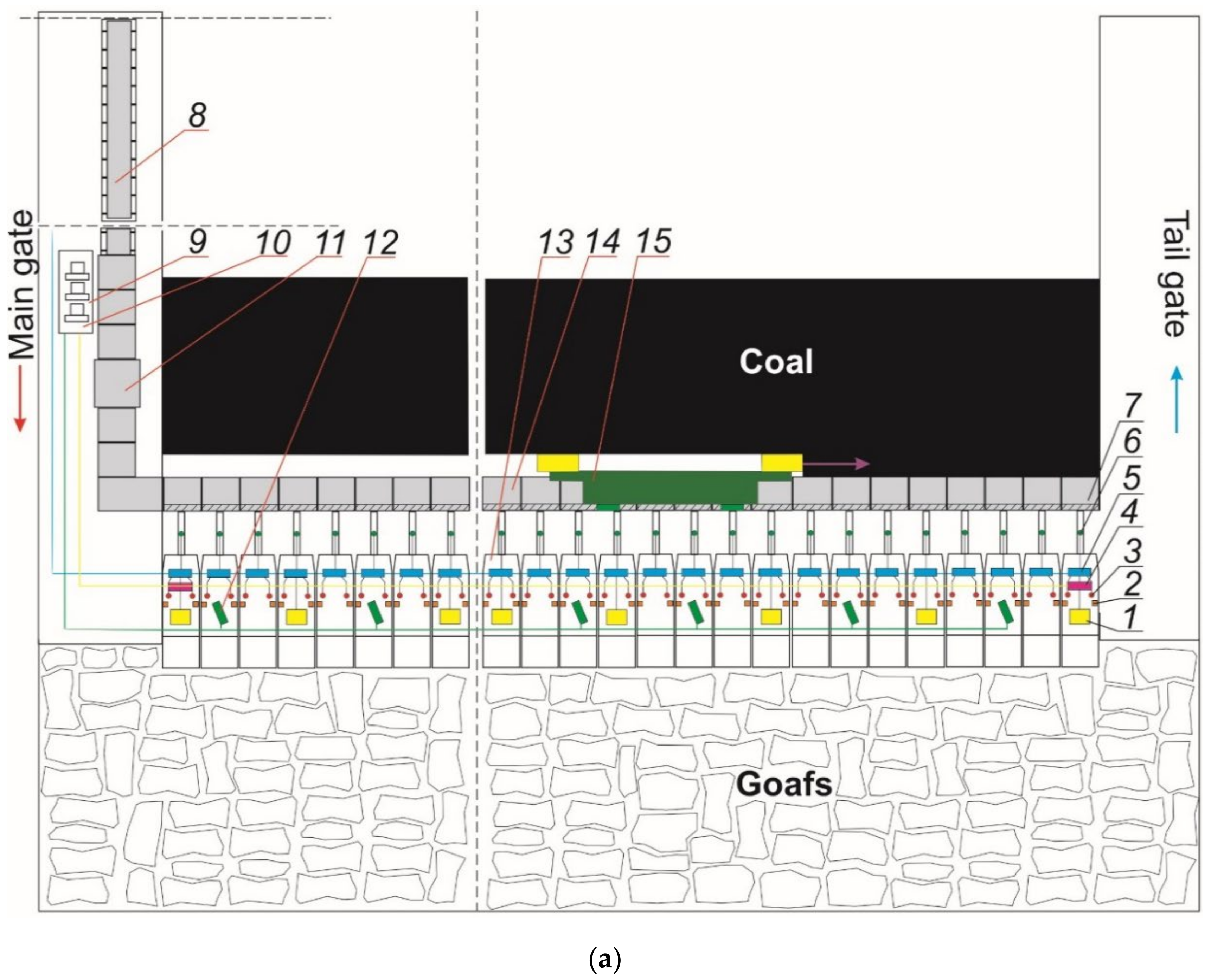
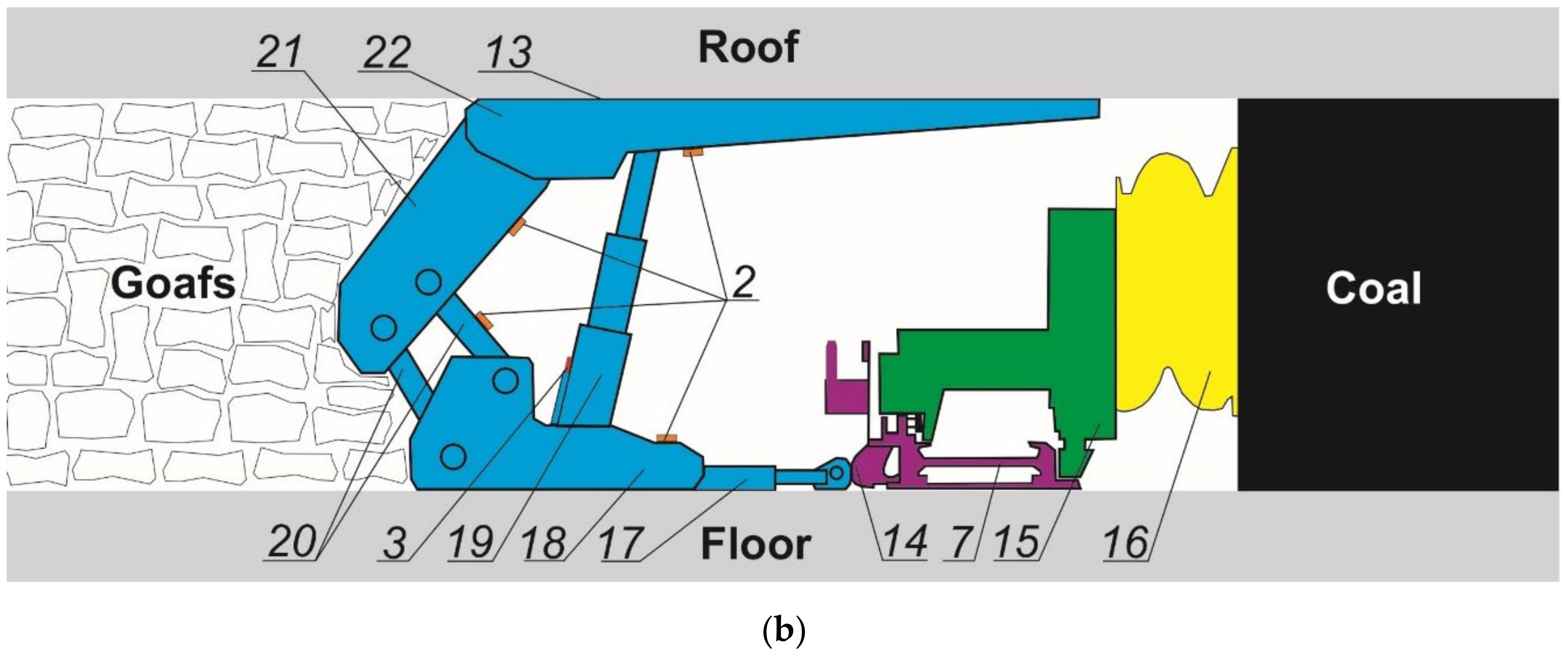
Arrangement of machines and equipment in a longwall complex: (a) cross-section of the longwall and (b) longitudinal section of the longwall, where 1—power supply, 2—inclinometer, 3—pressure sensor, 4—central controller, 5—controller with an executive block, 6—route sensor, 7—longwall scraper conveyor, 8—belt conveyor, 9—shearer control station with closed circuit television, Closed Circuit Television (CCTV) monitors and monitoring of operating parameters of the powered roof support, 10—scraper conveyor, 11—crusher, 12—CCTV camera, 13—powered roof support, 14—sliding system connection with a scraper conveyor, 15—shearer, 16—cutting unit, 17—sliding system, 18—floor base, 19—hydraulic leg, 20—lemniscate system, 21—shear support, and 22—roof.
Figure 1.
Arrangement of machines and equipment in a longwall complex: (a) cross-section of the longwall and (b) longitudinal section of the longwall, where 1—power supply, 2—inclinometer, 3—pressure sensor, 4—central controller, 5—controller with an executive block, 6—route sensor, 7—longwall scraper conveyor, 8—belt conveyor, 9—shearer control station with closed circuit television, Closed Circuit Television (CCTV) monitors and monitoring of operating parameters of the powered roof support, 10—scraper conveyor, 11—crusher, 12—CCTV camera, 13—powered roof support, 14—sliding system connection with a scraper conveyor, 15—shearer, 16—cutting unit, 17—sliding system, 18—floor base, 19—hydraulic leg, 20—lemniscate system, 21—shear support, and 22—roof.
Figure 2.
The concept of the devices that are part of the system; 1—intrinsically safe power supply, 2—controller, 3—electro-hydraulic executive block with control inserts, 4—solenoid valve, 5—control bar, 6–pressure sensor, 7—inclinometer, 8—underground computer, 9—surface computer, and 10—powered roof support section.
Figure 3.
Prototype devices that are part of the system; 1—intrinsically safe power supply, 2—controller, 3—electro-hydraulic executive block with control inserts, 4—solenoid valve, 5—control bar, 6—pressure sensor, 7—inclinometer, 8—underground computer, 9—surface computer, and 10—powered roof support section.
Figure 4.
Design of the underground computer together with the database.
Figure 4.
Design of the underground computer together with the database.
Figure 5.
Design of the surface computer together with the database.
Figure 5.
Design of the surface computer together with the database.
Figure 6.
Test monitoring equipment, where 1—oscilloscope, 2—laboratory power supply, 3—controller module, and 4—solenoid valve.
Figure 6.
Test monitoring equipment, where 1—oscilloscope, 2—laboratory power supply, 3—controller module, and 4—solenoid valve.
Figure 7.
Switch-on time and delay of the Pulse Width Modulation (PWM) and full PWM signal for the function of sliding up and down the legs: (a) supply voltage of 12 V for switching on time ∆X = 1.98 s, (b) supply voltage of 12 V for delay time. (c) Supply voltage of 11 V for switching on time ∆X = 1.98 s, (d) supply voltage of 11 V for delay time, (e) supply voltage of 10 V for start-up time ∆X = 1.98 s, and (f) supply voltage of 10 V for delay time.
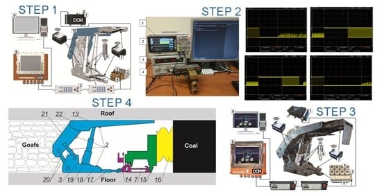
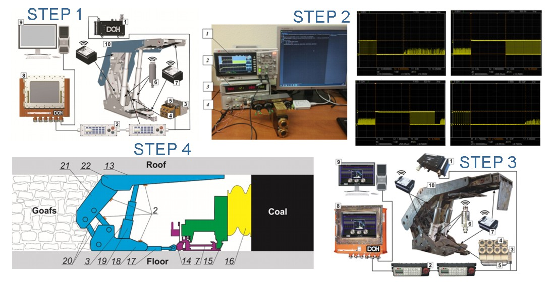
Figure 8.
The procedure together with the procedure for testing and evaluation for the introduction of an electro-hydraulic control system and a visualisation system for underground mine operation.
Figure 8.
The procedure together with the procedure for testing and evaluation for the introduction of an electro-hydraulic control system and a visualisation system for underground mine operation.
Table 1.
The result of the analysis designed to determine the level of the safety function.
Table 1.
The result of the analysis designed to determine the level of the safety function.
| Safety Integrity Level (SIL) | Probability of Dangerous Damage per Hour | Safety Performance Level (PL) | Hazard Assessment Method R |
|---|
| N/A | ≥10−5 to <10−4 | a | S1 |
| SIL 1 | ≥3 × 10⁻⁶ to <10−5 | b | S2 |
| SIL 1 | ≥10−6 to <3 × 10⁻⁶ | c | S3 |
| SIL 2 | ≥10−7 to <10−6 | d | S4 |
| SIL 3 | ≥10−8 to <10−7 | e | S5 |
| Publisher’s Note: MDPI stays neutral with regard to jurisdictional claims in published maps and institutional affiliations. |
© 2021 by the authors. Licensee MDPI, Basel, Switzerland. This article is an open access article distributed under the terms and conditions of the Creative Commons Attribution (CC BY) license (http://creativecommons.org/licenses/by/4.0/).


 ,
, 

_Spearing.png)


