
Combined NOx and NH3 Slip Reduction in a Stoker Boiler Equipped with the Hybrid SNCR + SCR System FJBS+


Abstract
:1. Introduction
- Lower maximum flue gas temperature
- Significant fluctuations of flue gas temperature in the combustion chamber
- Greater flame diffusion in the combustion chamber
- Different flue gas flow profile.
- (1)
- to examine the parameters of a novel SNCR installation called FJBS (Furnace Jet Boiler System) applied to a stoker boiler for the full range of boiler load: 12–30 MWth, which corresponds to 33–103% of the nominal load.
- (2)
- to investigate the effectiveness of a novel, hybrid FJBS+ installation (a combination of FJBS with a catalyst) applied to a stoker boiler, including a comparison of brand new and regenerated plate type TiO2-WO3-V2O5 catalyst,
- (3)
- to determine the fate of NH3 in combustion by-products (flue gas and fly ash) during the hybrid FJBS+ process,
- (4)
- to test an innovative method of ammonium removal from fly ash by high-temperature desorption on boilers’ grate.
2. Materials and Methods
3. Results and Discussion
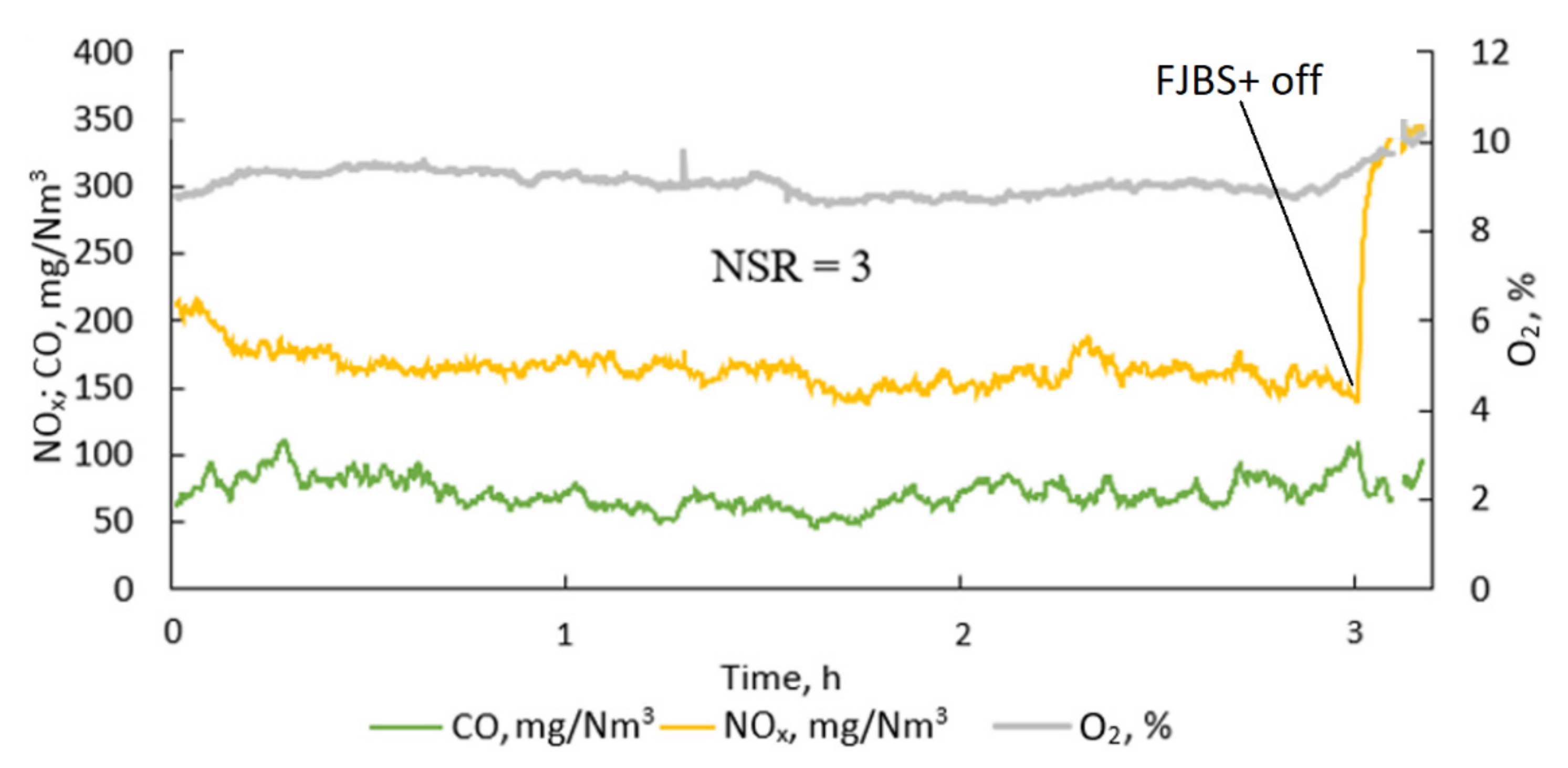
3.1. Selective Non-Catalytic Reduction FJBS
3.2. Hybrid SNCR + SCR System FJBS+
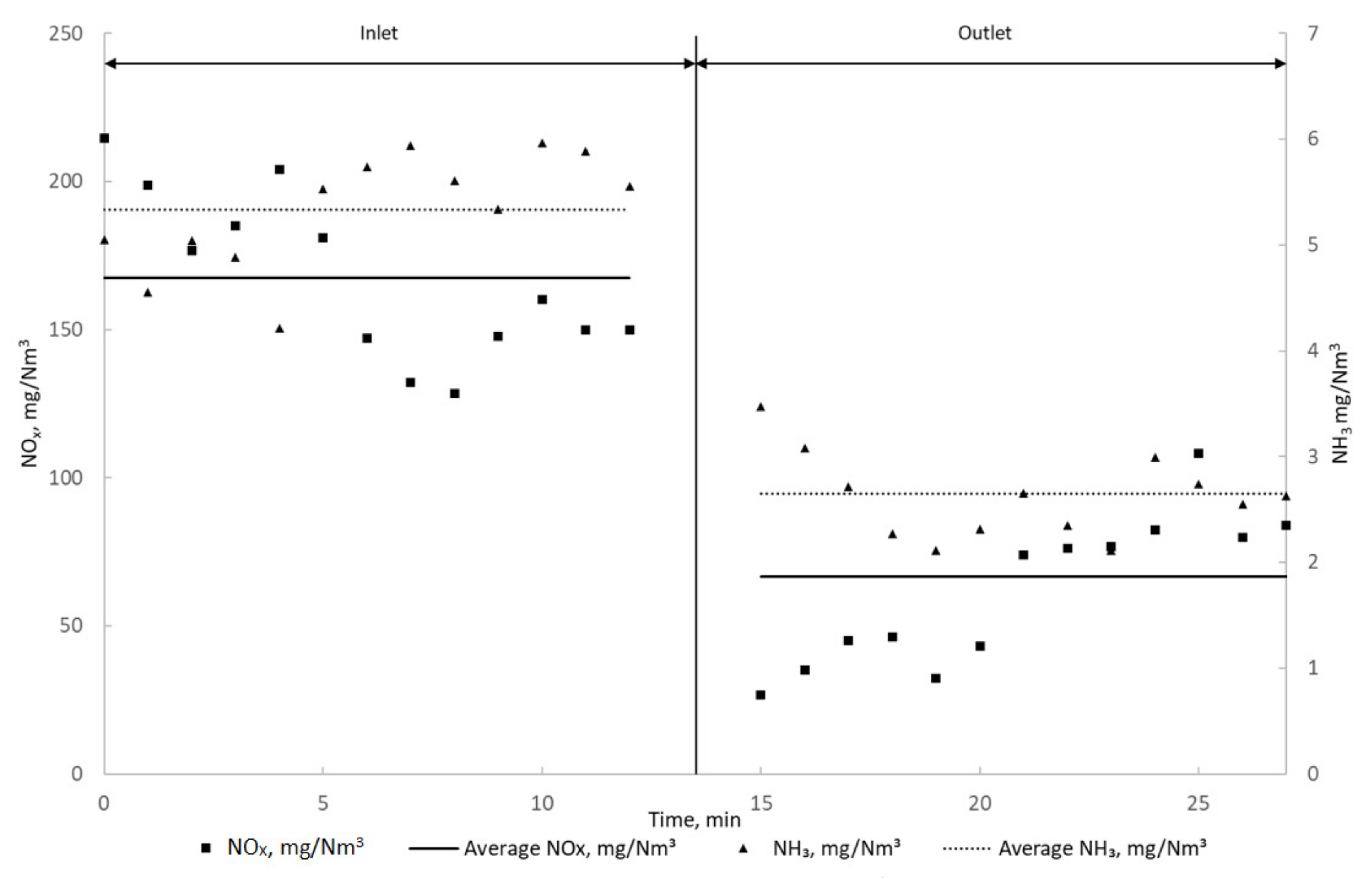
3.2.1. FJBS+ Part I: Low/Medium Boiler Load
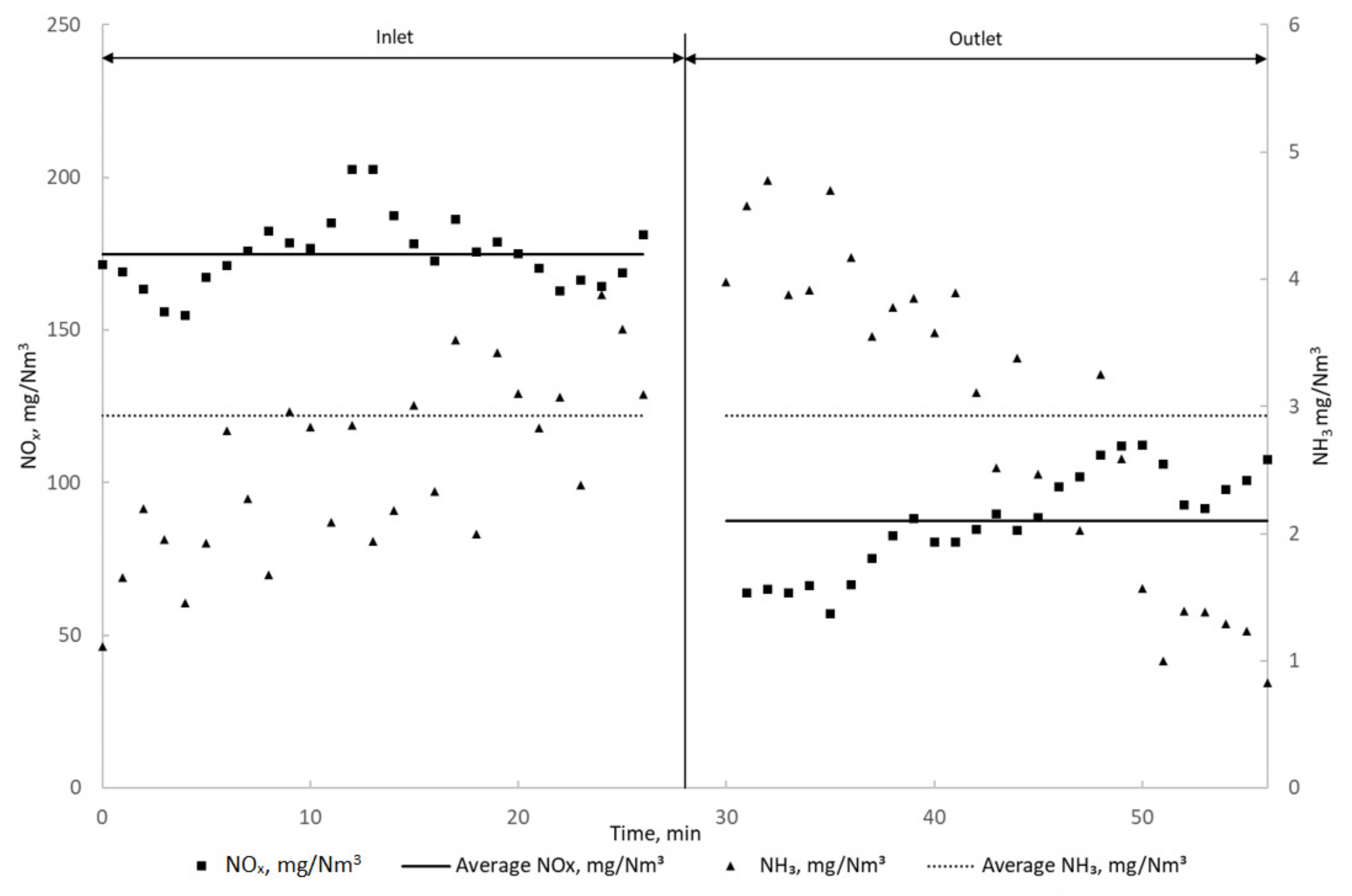
3.2.2. FJBS+ Part II: High Boiler Load
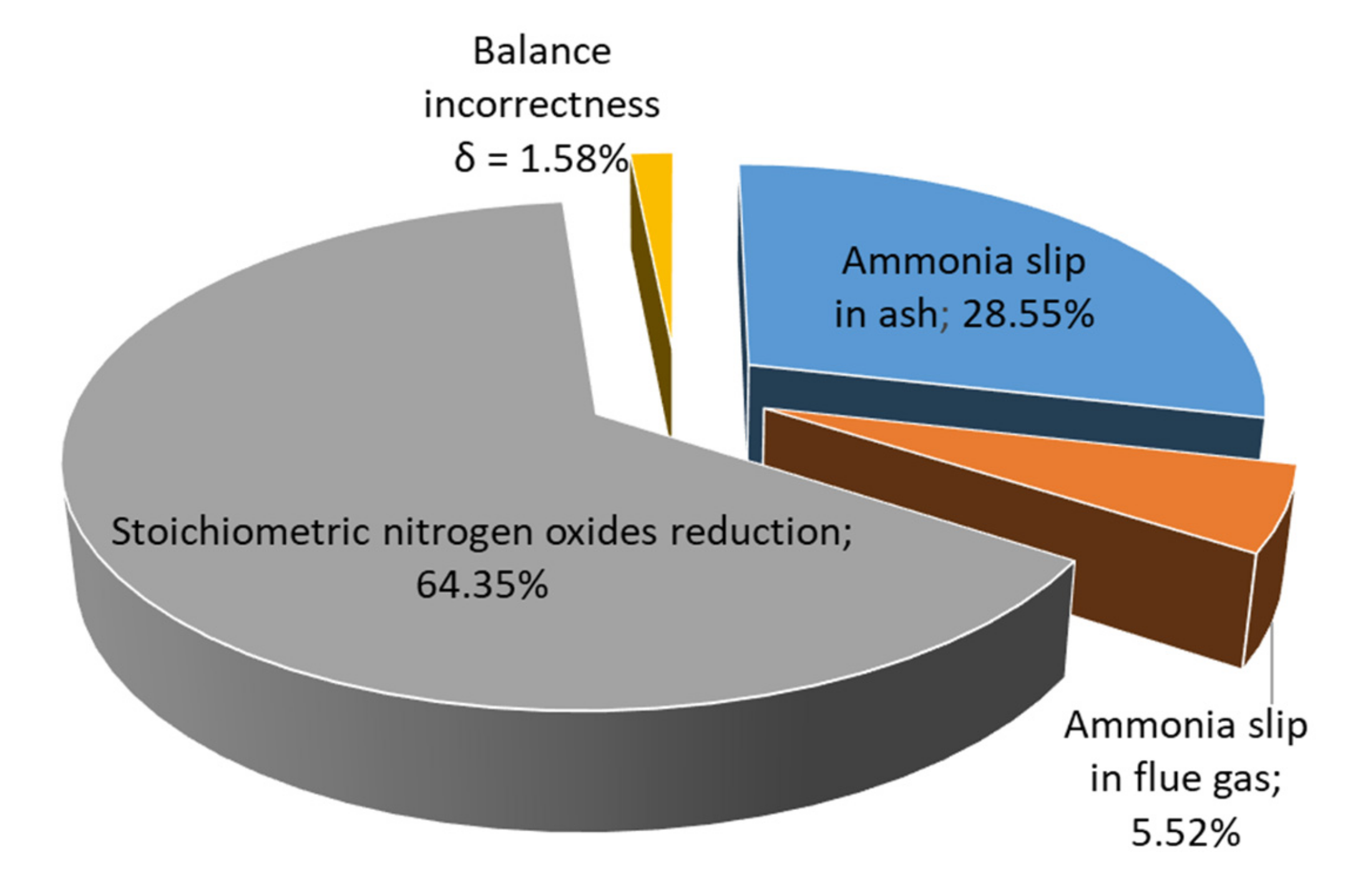
3.3. The Fate of NH3 in Combustion By-Products
3.4. Reduction of Ammonia in Fly Ash
4. Conclusions
Author Contributions
Funding
Institutional Review Board Statement
Informed Consent Statement
Data Availability Statement
Conflicts of Interest
References
- Busca, G.; Lietti, L.; Ramis, G.; Berti, F. Chemical and mechanistic aspects of the selective catalytic reduction of NO by ammonia over oxide catalysts: A Review. Appl. Catal. B Environ. 1998, 18, 1–36. [Google Scholar] [CrossRef]
- Bendrich, M.; Scheuer, A.; Hayes, R.E.; Votsmeier, M. Unified mechanistic model for standard SCR, Fast SCR, and NO2 SCR over a copper chabazite catalyst. Appl. Catal. B Environ. 2018, 222, 76–87. [Google Scholar] [CrossRef]
- Rosenberg, H.S.; Curran, L.M.; Slack, A.V.; Ando, J.; Oxley, J.H. Post combustion methods for control of NOx emissions. Prog. Energy Combust. Sci. 1980, 6, 287–302. [Google Scholar] [CrossRef]
- Muzio, L.J.; Quartucy, G.C.; Cichanowiczy, J.E. Overview and status of post-combustion NOx control: SNCR, SCR and hybrid technologies. Int. J. Environ. Poll. 2002, 17, 4. [Google Scholar] [CrossRef]
- Rota, R.; Antos, D.; Zanoelo, É.F.; Morbidelli, M. Experimental and modeling analysis of the NOxOUT process. Chem. Eng. Sci. 2002, 57, 27–38. [Google Scholar] [CrossRef]
- Daood, S.S.; Javed, M.T.; Gibbs, B.M.; Nimmo, W. NOx control in coal combustion by combining biomass Co-firing, oxygen enrichment and SNCR. Fuel 2013, 105, 283–292. [Google Scholar] [CrossRef]
- Lee, S.J.; Yun, J.G.; Lee, H.M.; Kim, J.Y.; Yun, J.H.; Hong, J.G. Dependence of N2O/NO decomposition and formation on temperature and residence time in thermal reactor. Energies 2021, 14, 1153. [Google Scholar] [CrossRef]
- Li, J.; Chang, H.; Ma, L.; Hao, J.; Yang, R.T. Low-temperature selective catalytic reduction of NOx with NH3 over metal oxide and zeolite catalysts—A Review. Catal. Today 2011, 175, 147–156. [Google Scholar] [CrossRef]
- Forzatti, P. Present status and perspectives in De-NOx SCR catalysis. Appl. Catal. A Gen. 2001, 222, 221–236. [Google Scholar] [CrossRef]
- Van Caneghem, J.; de Greef, J.; Block, C.; Vandecasteele, C. NOx reduction in waste incinerators by Selective Catalytic Reduction (SCR) Instead of Selective Non Catalytic Reduction (SNCR) compared from a life cycle perspective: A case study. J. Clean. Prod. 2016, 112, 4452–4460. [Google Scholar] [CrossRef]
- Gohlke, O.; Weber, T.; Seguin, P.; Laborel, Y. A New Process for NOx reduction in combustion systems for the generation of energy from waste. Waste Manag. 2010, 30, 1348–1354. [Google Scholar] [CrossRef]
- Lai, J.-K.; Wachs, I.E. A Perspective on the Selective Catalytic Reduction (SCR) of NO with NH3 by Supported V2O5WO3TiO2 Catalysts. ACS Catal. 2018, 8, 6537–6551. [Google Scholar] [CrossRef]
- Keobel, M.; Elsener, M.; Marti, T. NOx-Reduction in Diesel Exhaust Gas with Urea and Selective Catalytic Reduction. Comb. Sci. Technol. 1996, 121, 85–102. [Google Scholar] [CrossRef]
- Boningari, T.; Koirala, R.; Smirniotis, P.G. Low-temperature catalytic reduction of NO by NH3 over vanadia-based nanoparticles prepared by flame-assisted spray pyrolysis: Influence of various supports. Appl. Catal. B Environ. 2013, 140–141, 289–298. [Google Scholar] [CrossRef]
- Więckowski, Ł.; Krawczyk, P.; Badyda, K. Numerical investigation of temperature distribution in the furnace of a coal fired grate boiler in part load conditions. J. Power Technol. 2018, 97, 359–365. [Google Scholar]
- Krawczyk, P. Experimental investigation of N2O formation in selective non-catalytic NOx reduction processes performed in stoker boiler. Pol. J. Chem. Technol. 2016, 18, 104–109. [Google Scholar] [CrossRef] [Green Version]
- Krawczyk, P. The Designing Method of NOx Reduction Installation for Coal Stocker-Fired Boilers Using SNCR Technology; Oficyna Wydawnicza Politechniki Warszawskiej: Warsaw, Poland, 2019. (In Polish) [Google Scholar]
- Wejkowski, R.; Kalisz, S.; Tymoszuk, M.; Ciukaj, S.; Maj, I. Full-scale investigation of dry sorbent injection for NOx emission control and mercury retention. Energies 2021, 14, 7787. [Google Scholar] [CrossRef]
- Hjuler, K.; Dam-Johansen, K. Mechanism and kinetics of the reaction between sulfur dioxide and ammonia in flue gas. Ind. Eng. Chem. Res. 1992, 31, 2110–2118. [Google Scholar] [CrossRef]
- Bai, H.; Biswas, P.; Keener, T.C. Particle formation by ammonia-sulfur dioxide reactions at trace water conditions. Ind. Eng. Chem. Res. 1992, 31, 88–94. [Google Scholar] [CrossRef]
- Muzio, L.; Bogseth, S.; Himes, R.; Chien, Y.-C.; Dunn-Rankin, D. Ammonium bisulfate formation and reduced load SCR operation. Fuel 2017, 206, 180–189. [Google Scholar] [CrossRef]
- Flagiello, D.; di Natale, F.; Erto, A.; Lancia, A. Wet Oxidation Scrubbing (WOS) for flue-gas desulphurization using sodium chlorite seawater solutions. Fuel 2020, 277, 118055. [Google Scholar] [CrossRef]
- Flagiello, D.; di Natale, F.; Lancia, A.; Salo, K. Effect of seawater alkalinity on the performances of a marine diesel engine desulphurization scrubber. Chem. Eng. Trans. 2021, 86, 505–510. [Google Scholar]
- Poullikkas, A. Review of design, operating, and financial considerations in flue gas desulfurization systems. Energy Technol. Pol. 2015, 2, 92–103. [Google Scholar] [CrossRef]
- Flagiello, D.; Esposito, M.; di Natale, F.; Salo, K. A novel approach to reduce the environmental footprint of maritime shipping. J. Mar. Sci. Appl. 2021, 20, 229–247. [Google Scholar] [CrossRef]
- Peng, Y.; Li, J.; Si, W.; Luo, J.; Dai, Q.; Luo, X.; Liu, X.; Hao, J. Insight into deactivation of commercial SCR catalyst by arsenic: An Experiment and DFT Study. Environ. Sci. Technol. 2014, 48, 13895–13900. [Google Scholar] [CrossRef] [PubMed]
- Jiang, Y.; Gao, X.; Zhang, Y.; Wu, W.; Song, H.; Luo, Z.; Cen, K. Effects of PbCl2 on selective catalytic reduction of NO with NH3 over vanadia-based catalysts. J. Hazard. Mater. 2014, 274, 270–278. [Google Scholar] [CrossRef]
- Zheng, Y.; Jensen, A.D.; Johnsson, J.E. Laboratory investigation of selective catalytic reduction catalysts: Deactivation by potassium compounds and catalyst regeneration. Ind. Eng. Chem. Res. 2004, 43, 941–947. [Google Scholar] [CrossRef]
- Guo, Y.; Xu, X.; Gao, H.; Zheng, Y.; Luo, L.; Zhu, T. Ca-Poisoning effect on V2O5-WO3/TiO2 and V2O5-WO3-CeO2/TiO2 catalysts with different vanadium loading. Catalysts 2021, 11, 445. [Google Scholar] [CrossRef]
- Tang, F.; Xu, B.; Shi, H.; Qiu, J.; Fan, Y. The poisoning effect of Na+ and Ca2+ Ions Doped on the V2O5/TiO2 catalysts for selective catalytic reduction of NO by NH3. Appl. Catal. B Environ. 2010, 94, 71–76. [Google Scholar] [CrossRef]
- Li, X.; Li, J.; Peng, Y.; Si, W.; He, X.; Hao, J. Regeneration of commercial SCR catalysts: Probing the existing forms of arsenic oxide. Environ. Sci. Technol. 2015, 49, 9971–9978. [Google Scholar] [CrossRef]
- Lange, F. Infrared-spectroscopic investigations of selective catalytic reduction catalysts poisoned with arsenic oxide. Appl. Catal. B Environ. 1996, 8, 245–265. [Google Scholar] [CrossRef]
- Peng, Y.; Li, J.; Si, W.; Luo, J.; Wang, Y.; Fu, J.; Li, X.; Crittenden, J.; Hao, J. Deactivation and regeneration of a commercial SCR catalyst: Comparison with alkali metals and arsenic. Appl. Catal. B Environ. 2015, 168–169, 195–202. [Google Scholar] [CrossRef]
- Kröcher, O.; Elsener, M. Chemical deactivation of V2O5/WO3–TiO2 SCR catalysts by additives and impurities from fuels, lubrication oils, and urea solution. Appl. Catal. B Environ. 2008, 77, 215–227. [Google Scholar] [CrossRef]
- Khodayari, R.; Odenbrand, C.U.I. Regeneration of commercial TiO2-V2O5-WO3 SCR catalysts used in bio fuel plants. Appl. Catal. B Environ. 2001, 30, 87–99. [Google Scholar] [CrossRef]
- Shi, Y.; Zhang, P.; Fang, T.; Gao, E.; Xi, F.; Shou, T.; Tao, M.; Wu, S.; Bernards, M.T.; He, Y.; et al. In situ regeneration of commercial NH3-SCR catalysts with high-temperature water vapor. Catal. Commun. 2018, 116, 57–61. [Google Scholar] [CrossRef]
- Yu, Y.; Meng, X.; Chen, J.; Yin, L.; Qiu, T.; He, C. Deactivation mechanism and feasible regeneration approaches for the used commercial NH3-SCR Catalysts. Environ. Technol. 2016, 37, 828–836. [Google Scholar] [CrossRef]
- Chyliński, F.; Goljan, A.; Michalik, A. Fly ash with ammonia: Properties and emission of ammonia from cement composites. Materials 2021, 14, 707. [Google Scholar] [CrossRef] [PubMed]
- Michalik, A.; Babińska, J.; Chyliński, F.; Piekarczuk, A. Ammonia in fly ashes from flue gas denitrification process and its impact on the properties of cement composites. Buildings 2019, 9, 225. [Google Scholar] [CrossRef] [Green Version]
- Bittner, J.; Gasiorowski, S.; Hrach, F. Removing Ammonia from Fly Ash. Presented at the International Ash Utilization Symposium, Lexington, KY, USA, 22–24 October 2001. Paper #15. [Google Scholar]
- Mazur, M.; Janda, T.; Żukowski, W. Chemical and thermal methods for removing ammonia from fly ashes. Czasopismo Techniczne 2017, 6, 31–50. [Google Scholar] [CrossRef]
- Conn, R.; Sarubac, N.; Levy, E. Removing ammonia from fly ash. Lehigh Energy Update 2001, 19, 1–2. Available online: https://www.lehigh.edu/~inenr/leu/leu_28.pdf (accessed on 30 September 2021).
- Carbon Burn-Out Process. Available online: https://Flyash.Com/Products-and-Technologies/Carbon-Burn-out/ (accessed on 30 September 2021).
- Gąsiorowski, S.; Hrach, F. Method for Removing Ammonia from Ammonia Contaminated Fly Ash. U.S. Patent No. 6,077,494, 20 June 2000. [Google Scholar]
- O’Connor, D. Ammonia Removal from Fly Ash: Process Review, Headwaters Ammonia Slip Mitigation (ASMTM) Technology; EPRI: Palo Alto, CA, USA, 2005. [Google Scholar]
- Wang, H.; Ban, H.; Golden, D.; Ladwig, K. Ammonia release characteristic from coal combustion fly ash. Fuel Chem. Div. Preprints 2002, 47, 836–838. [Google Scholar]
- Kastner, J.R.; Miller, J.; Kolar, P.; Das, K.C. Catalytic ozonation of ammonia using biomass char and wood fly ash. Chemosphere 2009, 75, 739–744. [Google Scholar] [CrossRef] [PubMed]
- Shrestha, S.; Harold, M.P.; Kamasamudram, K.; Kumar, A.; Olsson, L.; Leistner, K. Selective oxidation of ammonia to nitrogen on Bi-Functional Cu–SSZ-13 and Pt/Al2O3 monolith catalyst. Catal. Today 2016, 267, 130–144. [Google Scholar] [CrossRef]
- Chmielarz, L.; Węgrzyn, A.; Wojciechowska, M.; Witkowski, S.; Michalik, M. Selective Catalytic Oxidation (SCO) of ammonia to nitrogen over hydrotalcite originated Mg–Cu–Fe Mixed Metal Oxides. Catal. Lett. 2011, 141, 1345–1354. [Google Scholar] [CrossRef] [Green Version]
- Garbacz, P.; Wejkowski, R. Numerical research on the SNCR method in a grate boiler equipped with the innovative FJBS system. Energy 2020, 207, 118240. [Google Scholar] [CrossRef]
- Hernik, B. Numerical calculations of the WR-40 boiler with a furnace jet boiler system. Energy 2015, 92, 54–66. [Google Scholar] [CrossRef]


| Boiler Load MWth | NOx Emission without FJBS mg NOx/Nm3 at 6% O2 | NOx Emission with FJBS mg NOx/Nm3 at 6% O2 | NOx Reduction % |
|---|---|---|---|
| >14.5 | 320 | 168 | 48% |
| 14.5–27 | 340 | 169 | 50% |
| 29.5 | 375 | 174 | 53% |
| Boiler Load MWth | NOx Emission Inlet of New Catalyst CN mg NOx/Nm3 | NOx Emission Outlet of New Catalyst CN mg NOx/Nm3 | NOx Conversion on New Catalyst CN % | NOx Emission Inlet of Regenerated Catalyst CR mg NOx/Nm3 | NOx Emission Outlet of Regenerated Catalyst CR mg NOx/Nm3 | NOx Conversion on Regenerated Catalyst CR % |
|---|---|---|---|---|---|---|
| 12.5 | 185 | 82 | 55 | 130 | 67 | 48 |
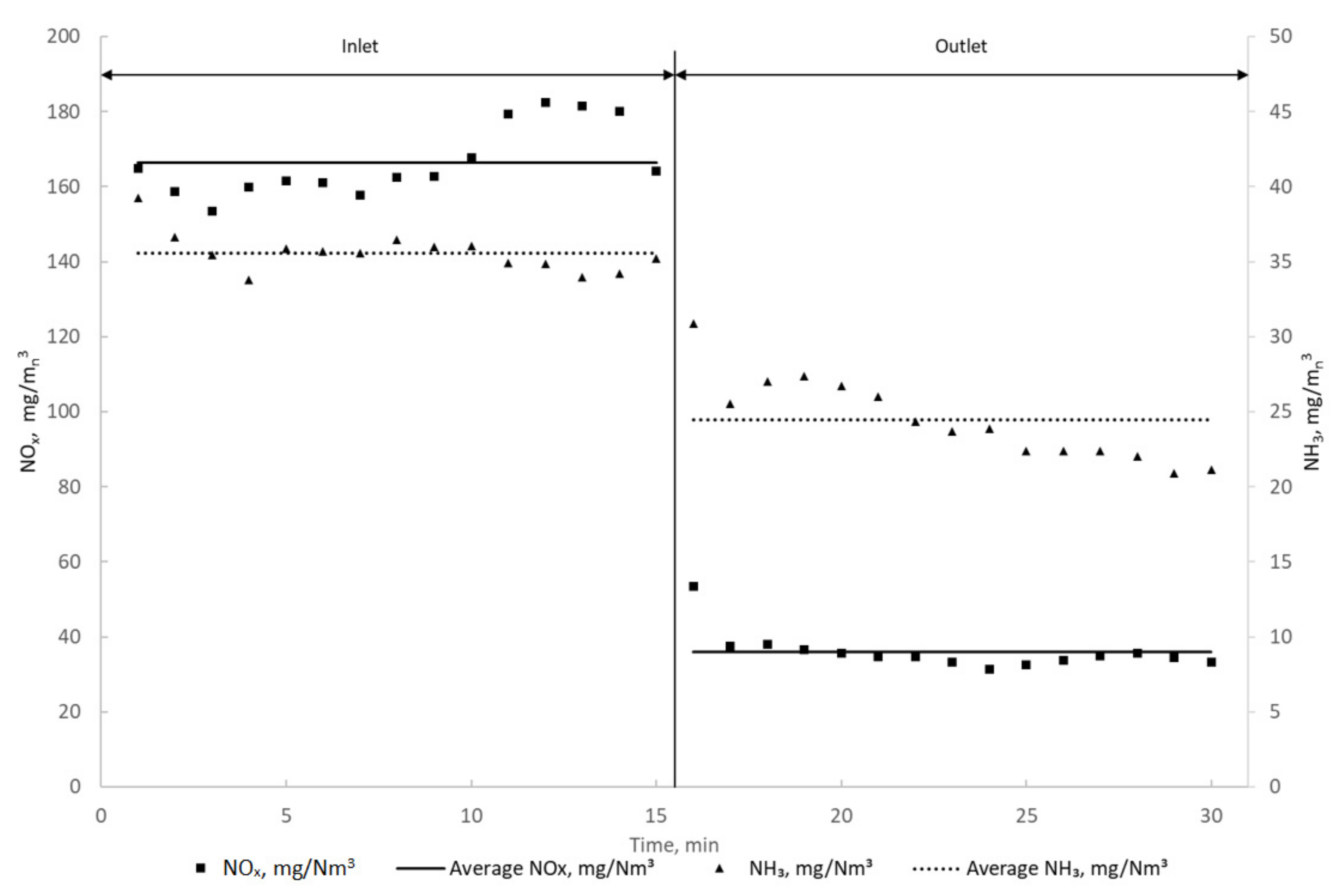
| 18.5 | 167 | 34 | 80 | 124 | 53 | 57 |
| Boiler Load MWth | NOx Emission at the Inlet of New Catalyst CN mg NOx/Nm3 | NOx Emission at the Outlet of New Catalyst CN mg NOx/Nm3 | NOx Conversion on New Catalyst CN % | NOx Emission at the Inlet of Regenerated Catalyst CR mg NOx/Nm3 | NOx Emission at the Outlet of Regenerated Catalyst CR mg NOx/Nm3 | NOx Conversion on Regenerated Catalyst CR % |
|---|---|---|---|---|---|---|
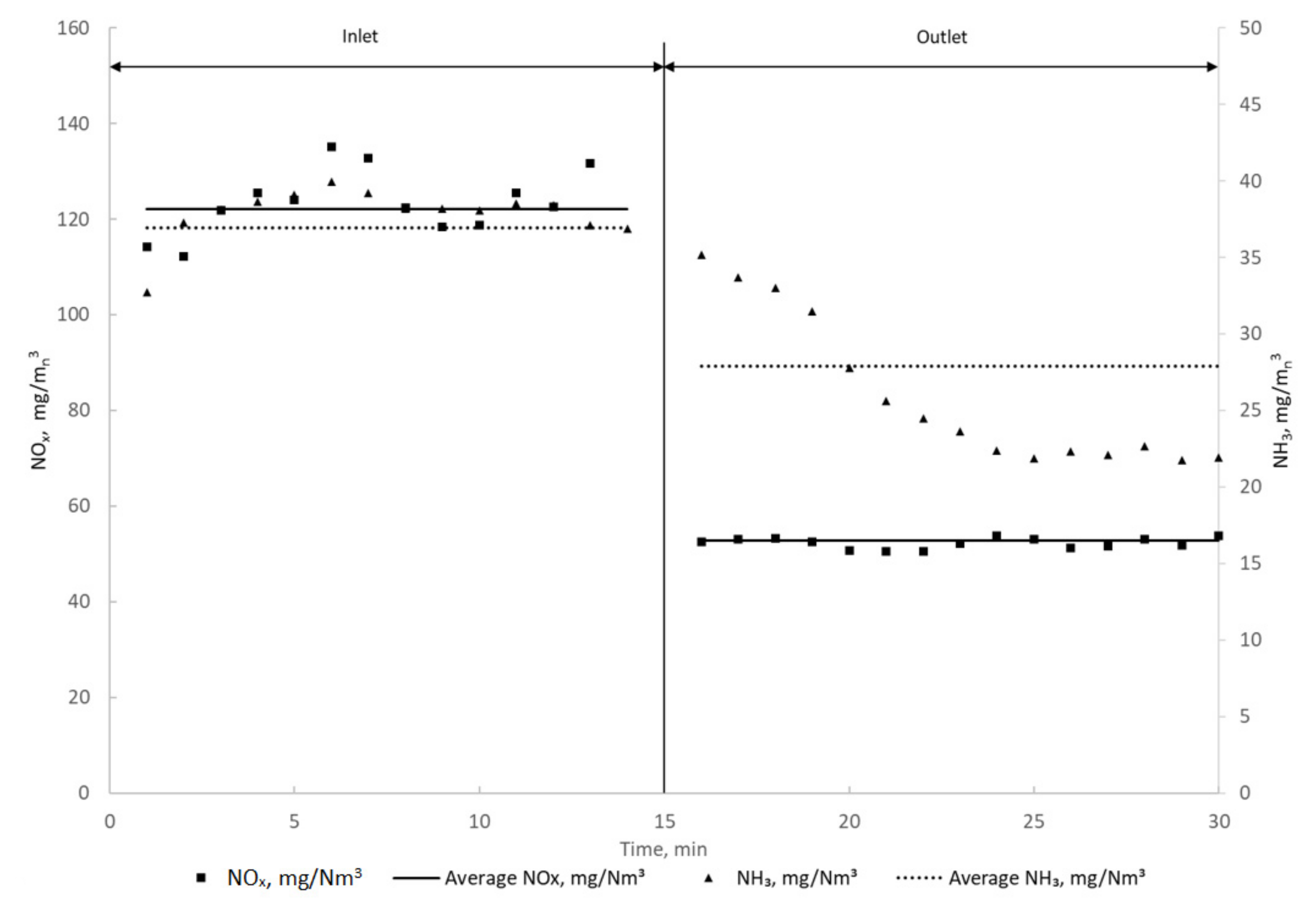
| 28 | 170 | 63 | 63 | 185 | 93 | 50 |
| Parameter | Symbol | Value | Unit |
|---|---|---|---|
| Urea solution volumetric flow | 24 | l/h | |
| Solution density | ρ | 1132 | kg/m3 |
| Urea concentration in solution | 40 | % | |
| Urea dose | 0.003019 | kg/s |
| Parameter | Symbol | Value | Unit |
|---|---|---|---|
| Ammonia in fly ash (ash output) | |||
| Fly ash mass flow | 0.194 | kg/s | |
| Ammonia content in fly ash | 2517 | mg/kg | |
| Ammonia stream in ash | 0.0004883 | kg/s | |
| Urea stream equivalent | 0.0008617 | kg/s | |
| Ammonia in flue gas (slip) | |||
| Flue gas volume flow | 10.5 | m3n/s | |
| Flue gas ammonia content | 9 | mg/m3n | |
| Ammonia stream in flue gas | 0.0000945 | kg/s | |
| Urea stream equivalent | 0.0001668 | kg/s | |
| NOx reduction | |||
| Avg. NOx concentration in flue gas without reduction | 310 | mg/mn3 | |
| Avg. NOx concentration in flue gas with the reduction system | 125 | mg/mn3 | |
| Avg. NOx reduction | 185 | mg/mn3 | |
| Urea stream for NOx reduction | 0.0019425 | kg/s | |
| Name | Symbol | Value | Unit | |
|---|---|---|---|---|
| Input | Urea dose | 0.003019 | kg/s | |
| 100 | % | |||
| Output | Ammonia in fly ash | 0.000862 | kg/s | |
| 28.55 | % | |||
| Ammonia in flue gas | 0.0001668 | kg/s | ||
| 5.52 | % | |||
| NOx reduction | 0.001943 | kg/s | ||
| 64.35 | % | |||
| Output total | 0.002971 | kg/s | ||
| 89.20 | % | |||
| Balance incorrectness δ | 1.58 | % | ||
| Parameter | Initial NH3 Content in Fly Ash mg/kg | NH3 Content after Laboratory Desorption mg/kg | NH3 Content after Full-Scale Desorption mg/kg | |
|---|---|---|---|---|
| Sample Number | ||||
| 1 | 479 | <6.1 | 7.3 | |
| 2 | 1326 | <6.1 | 32.3 | |
| 3 | 3796 | <6.1 | <6.1 | |
Publisher’s Note: MDPI stays neutral with regard to jurisdictional claims in published maps and institutional affiliations. |
© 2021 by the authors. Licensee MDPI, Basel, Switzerland. This article is an open access article distributed under the terms and conditions of the Creative Commons Attribution (CC BY) license (https://creativecommons.org/licenses/by/4.0/).
Share and Cite
Wejkowski, R.; Kalisz, S.; Garbacz, P.; Maj, I. Combined NOx and NH3 Slip Reduction in a Stoker Boiler Equipped with the Hybrid SNCR + SCR System FJBS+. Energies 2021, 14, 8599. https://doi.org/10.3390/en14248599
Wejkowski R, Kalisz S, Garbacz P, Maj I. Combined NOx and NH3 Slip Reduction in a Stoker Boiler Equipped with the Hybrid SNCR + SCR System FJBS+. Energies. 2021; 14(24):8599. https://doi.org/10.3390/en14248599
Chicago/Turabian StyleWejkowski, Robert, Sylwester Kalisz, Przemysław Garbacz, and Izabella Maj. 2021. "Combined NOx and NH3 Slip Reduction in a Stoker Boiler Equipped with the Hybrid SNCR + SCR System FJBS+" Energies 14, no. 24: 8599. https://doi.org/10.3390/en14248599