Review

A Review on Power Electronics Technologies for Power Quality Improvement

1
Centro ALGORITMI, University of Minho, 4800-058 Guimaraes, Portugal
2
Department of Electronics and Communications, Rio de Janeiro State University, Rio de Janeiro 20550-900, RJ, Brazil
*
Author to whom correspondence should be addressed.
Energies 2021, 14(24), 8585; https://doi.org/10.3390/en14248585
Submission received: 30 July 2021 / Revised: 7 December 2021 / Accepted: 8 December 2021 / Published: 20 December 2021
(This article belongs to the Special Issue Active Power Filters and Power Quality)

Abstract

:
Nowadays, new challenges arise relating to the compensation of power quality problems, where the introduction of innovative solutions based on power electronics is of paramount importance. The evolution from conventional electrical power grids to smart grids requires the use of a large number of power electronics converters, indispensable for the integration of key technologies, such as renewable energies, electric mobility and energy storage systems, which adds importance to power quality issues. Addressing these topics, this paper presents an extensive review on power electronics technologies applied to power quality improvement, highlighting, and explaining the main phenomena associated with the occurrence of power quality problems in smart grids, their cause and effects for different activity sectors, and the main power electronics topologies for each technological solution. More specifically, the paper presents a review and classification of the main power quality problems and the respective context with the standards, a review of power quality problems related to the power production from renewables, the contextualization with solid-state transformers, electric mobility and electrical railway systems, a review of power electronics solutions to compensate the main power quality problems, as well as power electronics solutions to guarantee high levels of power quality. Relevant experimental results and exemplificative developed power electronics prototypes are also presented throughout the paper.

1. Introduction

Aiming to modernize the traditional power systems, smart grids are emerging, supported by power electronics and digital technologies, as the next-generation of power systems with the objective of satisfying a set of relevant growing concerns, while ensuring environmentally-friendly principles. Evidently, the pathway targeting such a reality is complex and, among others, the key concerns are related to flexibility among systems, efficiency in the production and consumption, distributed generation (DG) and energy storage, reliability of power electronics, smart metering systems, power management, smart homes and cities, communication infrastructures, battery charging systems for more electric mobility, microgrids, controllable electrical appliances, and embracing all of these topics the power quality, both from the power grid and the final-user perspectives [1]. Additionally, in this context, cities are changing toward smart cities and their concepts, and concerning the evaluation of technologies, cost-benefit analysis and societal impacts are presented in [2]. Additionally, a survey about the fundamental management systems in terms of the request for advanced metering infrastructures for future grids is presented in [3]. Globally, considering that the new technologies require more and more power electronics systems, new opportunities for power management are also emerging, where the intercommunication between all of them reinforces the major role of information and communication technologies. However, the widespread use of power electronics converters leads, inevitably, to issues associated with power quality. In fact, power quality is recognized as a standout among the greatest indispensable issues for the successful implementation of smart grids, despite power quality being a well-known concern presented in the conventional power grids. This new importance of power quality is due to several factors, including the increasing use of electrical appliances, mainly in the industrial sector, and the electrical appliances with nonlinear behavior in the residential sector. The essential concerns of power quality are associated with additional costs, losses in product quality, and malfunctioning of electrical appliances, both in terms of premature fails and total failure. Consequently, power quality can represent an enormous harmful effect regarding several sectors, mainly industrial, commercial, and residential, each one presenting different requirements from a power quality perspective. Moreover, e.g., within the industrial sector, particular attributes in terms of power quality can be identified, forcing the adoption of specific solutions to mitigate power quality problems. Aligned with this perspective, the implementation of these solutions reflects additional costs. Regarding the residential sector, in principle, the conventional electrical appliances tend not to be harmfully affected due to power quality issues, i.e., they depend less on the power quality offered by the power grid during its normal operation. Nevertheless, by considering the sophisticated advances of technologies for new and emerging electrical appliances, presenting new functionalities (e.g., IoT technologies and communications), it is predictable that they can be more susceptible to power quality problems soon.
A review of power quality issues is presented in [4], including techniques used to reduce power quality disturbances, harmonization of protection approaches, and the importance of considering power quality concerns during the design stage. The assessment of new power quality indices that occurs during transient disturbances is investigated in [5], which are based on the time-frequency distribution of a transient disturbance. The importance of power quality as an educational subject is also relevant, as introduced in [6] The predictable and potential adverse consequences of power quality, due to the introduction of smart technologies, are presented in [7], including perspectives of microgrids and demand-side management. The application of a novel custom power device for real-time reactive power compensation and improvement of the power grid voltage is presented in [8]. An engagement of electromagnetic compatibility and power quality issues is presented in [9], also considering the interoperability of electrical appliances in power grids. The use of a smart electrical appliance as a contribution to reducing power quality problems is presented in [10], specifically, four-quadrant equipment dedicated to supporting ancillary services of the power grid, in addition to its major functions of voltage and frequency regulation, is investigated. An overview of control strategies dedicated to improving power quality in hybrid microgrids is introduced in [11], including different types of power quality issues and key technologies of power electronics in terms of converters. Some novel methods for investigating harmonics contextualized with forthcoming grid applications are presented in [12] with the perspective to diminish vast amounts of harmonic data.
As above-mentioned, power quality is an area that covers many topics, and, specifically, the aim and contribution of this paper are to present a comprehensive review of power electronics technologies targeting the improvement of power quality in different scenarios of application. Covered in this paper are power quality phenomena related to different electrical systems and appliances and solutions to overcome power quality problems are presented. Therefore, this paper offers an intensive review, with 367 references, covering the collection and precise description of the main technologies that require power electronics systems and the respective influence on power quality, as well as the contextualization of solutions based on power electronics systems to enhance power quality. More specifically, the main contributions of this paper are summarized as follows: (a) Review and classification of the main power quality problems and the respective context with the standards; (b) Review of power quality problems related to the power production from renewables, the contextualization with solid-state transformers, electric mobility and electrical railway systems; (c) Review of power electronics solutions to compensate the main power quality problems, as well as power electronics solutions to guarantee high levels of power quality; (d) Exemplificative experimental results of solutions to improve power quality.
The rest of the paper is organized as follows. Section 2 presents the main power quality phenomena. Section 3 presents the power quality problems related to power production from renewable energy sources (RES). Section 4 presents the contribution of the solid-state transformer (SST) for mitigating power quality issues, including all the technologies that are associated. Section 5 presents power quality problems that can occur due to the integration of electric mobility, specifically associated with on-board and off-board battery chargers (both single-phase and three-phase). Section 6 shows the power electronics solutions based on shunt and series active power filters (APF), unified power quality conditioners (UPQC), as well as uninterruptible power supplies (UPS), to compensate for power quality problems of voltage and current. Section 7 presents the power electronics solutions that can be adopted to diminish the effects of power quality deterioration caused by the electric railway systems. Section 8 presents power electronics solutions based on power factor correction (PFC) topologies and innovative variable speed drives as a contribution to mitigating power quality problems. Section 9 presents an overview of future research trends, and, finally, Section 10 presents the main conclusions.

2. Power Quality Phenomena

Power quality phenomena include several definitions, ranges, and criteria, which should be defined by equipment manufacturers, international code agencies, electric power grid operators, and consumers. The cost of poor power quality can be related to extra energy consumption and to hidden expenses such as power interruption due to false protection, data losses, and equipment damage. The total costs of poor power quality are high. The annual cost is estimated to be between USD 119–188 billion in U.S companies and EUR 150 billion in the European industry [13]. From here, the main objective of power quality norms is to regulate the quality of electrical energy, which must respond to the needs of a determined electrical system. Accordingly, various power quality definitions were suggested by different organizations. For example, the norm of electromagnetic compatibility EN61000-4-30: testing and measurement techniques—power quality measurement methods, and EN-50160 standard: voltage characteristics in public distribution systems [14]. On the other hand, non-linear loads are widely used in industries today and drain currents from the power grid with a high total harmonic distortion (THD), which causes a certain power quality deterioration. These special loads connected to the three-phase ac power grid at high-voltage (HV) or medium-voltage (MV) levels also have their own power quality norms. As an example, in the electrified railway applications, the norm of supply voltages of traction systems is EN 50163 [15].
AC power quality problems remain present in many electrical installations, such as problems of low power factor, system unbalances, transient phenomena, causing problems related to energy efficiency and connectors oversizing. All these problems represent losses, both in terms of money and energy. In addition, power quality deterioration may interrupt the execution of processes, reducing the equipment’s life span [16]. The differences between the ac power quality phenomena and the dc ones arise from the constant voltage in the dc power grid and the alternating voltage in the ac power grid. Hence, it is possible to say that dc power quality phenomena will not have the same severity and occurrence level as the ac ones. The effect of power electronic converters on the power quality of dc power grids is crucial since these power converters are indispensable for dc transmission and distributed generation systems. The next items present some of the power quality phenomena and the indices to assess the severity of a given power quality problem. Figure 1 presents waveforms of different types of power quality problems.

2.1. System Unbalance

The three-phase ac power grid is considered balanced if the three-phase voltage and current waveforms are sinusoidal and have an equal amplitude with a 120° phase shift between consecutive phases. However, if these conditions are not met, the system is called unbalanced. The main causes of system unbalance are the connection of high single-phase loads (e.g., electrified railways) to the three-phase ac power grid and transmission lines without transposition. The main effects of system unbalance are the increase in losses and temperature in electric motors [17]. In addition, the unbalance leads to creating symmetrical components, specifically, negative sequence components (NSC) and zero sequence components (ZSC). The NSC may harm the generators linked to the power grid. This is because NSC may produce negative components of current which induce a double-frequency current in the rotor parts and field windings. These double-frequency currents may cause high temperatures in a very short period. During the normal operation, it is possible for the supply voltages to vary from their effective values [18]. The standard EN-50160 defines that under normal conditions during each weekly period, 95% of the average effective values of 10 min must be in the range Un ± 10%, where Un is the nominal root mean square (RMS) value. There is a limit for NSC of 2% in respect to positive sequence components [19]. On the other hand, the three-phase currents unbalance may result in three-phase voltage unbalance. By another meaning, the NSC of currents produces NSC of voltages as well. As a result, a single-phase load is normally causing the NSC of currents, if they are not compensated, they may cause power perturbation, as well as increase the power consumption costs [20].

2.2. Voltage Sags

Voltage sags in ac power grids can be defined as a temporary decrease in the RMS supply voltage to a value between 90% and 10% of the declared value of RMS voltage for a period longer than one fundamental cycle. For voltage sags in dc power grids, the Vdc value substitutes the ac RMS value. After the voltage sag took place, the voltage should be restored in a short period of time. Based on the EN-50160 standard, a duration of voltage sag may present a time-period between 10 ms to 1 min. Voltage sags in ac power grids are events that can be caused by starting of electric motors, short circuits in neighboring facilities, and energizing of transformers. The main problems associated with voltage sags are the variation in torque and speed of the electric motors, disturbance, and interruption in the operation of sensitive equipment, such as microprocessors and protection devices. Voltage sags in the dc power grid may appear at the high-voltage dc-bus due to the fast switching of the power converters [21]. The value of voltage sag is defined as the difference between the RMS ac voltage/dc voltage obtained during the voltage sag and the nominal value of RMS ac voltage/dc voltage [22].

2.3. Voltage Fluctuations (Flickers)

It is hard to define the direct reason behind the low-frequency ac voltage fluctuations, where this issue did not get enough interest from researchers. AC voltage fluctuations can be caused by lightning, starting of large high-power motors, disconnecting of heavy loads, and arc welding machines. There are some types of ac voltage fluctuations that, due to their characteristics, can cause frequent variations in the luminous intensity of fluorescent lamps, a phenomenon usually known as flicker. The flickering in light sources has been problematic since the beginning of power distribution systems, and with the increase in installed power and industrial customers, the phenomenon of voltage flickering has grown rapidly. In addition, this power quality problem can also result in failure or incorrect operation of sensitive electronic equipment and shorten its life span. To assess this phenomenon, there are different metrics used [20]. The norm EN-50160 refers to the standards defined by the International Electrotechnical Committee (IEC) to measure this phenomenon in the public distribution system. The norm IEC 61000-3-3 refers to the limitation of voltage fluctuations in public low-voltage systems and at phase current/phase voltage equal to or less than 16 A/250 V [23]. To evaluate the severity of this phenomenon, the standards EN-50160 and IEC 61000-3-3 define short-term flicker severity, where flickers are measured over a period of ten minutes, and long-term severity is normally calculated from a sequence of twelve short-term severity measurements over two-hour intervals [20]. The flicker severity uses flicker indices from direct measurement of this phenomenon, then the values of long-term flickers are compared with the permissible flicker levels given in the aforementioned standards.
On the other hand, and regarding the dc power grids, dc voltage fluctuations may appear on the dc-bus of the dc power grids due to a large load power change and high-power consumption, e.g., dc distribution generation grids. The greater the power capacity of the dc power grid compared to the load power consumption, the greater the dc voltage fluctuations in the dc-bus will be caused. The dc voltage fluctuations are a root cause for protection equipment malfunctioning, such as dc circuit breakers, and may affect the converter control stability [24].

2.4. Transient Overvoltages and Inrush Currents

Transient overvoltage is a fast phenomenon, which can be oscillatory, or non-oscillatory, with a rise time that can be less than 1 μs up to a few ms. The magnitude of this phenomenon, as well as its energy and duration, are related to the events that originate them. The main causes of transient overvoltage are lightning strikes, the operation of fuses, energizing capacitors, etc. On the other hand, the consequences of this phenomenon may lead to damage or stoppage of sensitive equipment, flickering of lighting and screens. The effect may be a gradual, accumulative effect that may cause hardware failure in the equipment [25].
In ac power grids, inrush currents are normally caused due to energizing a transformer or an induction motor or can be due to a pre-charge circuit. On the other side, in dc power grids where power electronic converters are commonly used, power filters are usually placed at the connection point with the dc-bus. The capacitance of these power filters may draw high inrush current. General characteristics and the value of the inrush current are highly influenced by the total circuit impedance. For instance, the high filter capacitance or the insertion of a high number of batteries integrated into a dc-distributed generation system will cause a high inrush current [26].

2.5. Harmonics and Interharmonics

Voltage harmonics are multiple spectral components that have the double, third, fourth, etc., the fundamental frequency of a voltage waveform. In addition, there are other components, not integer multiples of the fundamental frequency, called inter-harmonics. Among the most critical are the 3rd order harmonic contents that have three-times the fundamental frequency value. The 3rd order harmonic contents are generated when single-phase non-linear loads are under operation (e.g., rectifiers and variable speed drives). Harmonic contents are considered as one of the main origins for power quality deterioration in industrial applications. Harmonics suppression could be carried out either by installing passive filters at the load side or by using APF that are more expensive and more effective for the purpose of harmonics cancellation [27], as demonstrated in the next sections. To measure the harmonic distortion, the THD is a metric that is used to quantify the distortion of a given voltage or current waveform. According to the standard EN-50160 under normal operating conditions, for each period of one week, 95% of the obtained average voltage values during 10 min for each harmonic voltage should not exceed the values given in Table 1. The THD (including the harmonics up to the 40th order) must not exceed 8% at MV or HV levels, and 4% at the extra-high-voltage (EHV) level [20].
As in the case of voltages, an analysis of the currents that circulate in each electrical system can also be performed, thus measuring their distortion. The measurement methods used in the case of this phenomenon are generally the same as those used for voltages. Although the standard EN-50160 does not mention limits for the current harmonics that the loads produce, there is a set of standards that limit the emission of these harmonics, such as the IEEE 519 [28] which states the harmonics distortion rules for the design of electrical systems, the IEC 61000-3-2 [29] which defines the harmonics limitation for equipment that draws phase current less than 16 A, and the IEC 61000-3-12 which describes the harmonics limitation for equipment that draws phase current more than 16 A and less than 75 A [30]. Harmonics limits according to IEEE 519 standard are presented in Table 2. For more information on harmonic limits according to IEC 61000-3-2 and IEC 61000-3-12, refer to [29,30], respectively.
Under normal operating conditions, current and voltage harmonics do not generally exceed the limits stated by the standard. However, with harmonic resonance conditions presented in the power grid, voltage and/or current harmonics can get significantly stronger. Two types of harmonic resonance may occur: 1—Series resonance appears when the circuit impedance is getting the lowest at certain frequencies, leading to excessive heating of power transmission lines and high-power losses due to current amplification; 2—Parallel resonance appears when the circuit impedance is getting the highest at certain frequencies, resulting in excessive voltage excursion and protection equipment malfunctioning. This power quality phenomenon was recently analyzed in AC electrified railways due to the distributed LC circuits along the overhead catenary line, which may result in series or parallel resonance at some frequencies. More details can be found in [32].
Interharmonics are defined as “A frequency component that is not an integer multiple of the fundamental frequency at which the power grid is operating (e.g., 50 Hz or 60 Hz) [20]. In power electronics applications, interharmonics are normally generated when there is asynchronous switching of power converters with the power system frequency. The interharmonics may pass through the dc-bus of the power converter from one ac system to another. On the other hand, when saturation occurs in transformers or induction motors, interharmonics can be introduced to the power grid and can increase during the start-up period. For instance, the traction system power supplies that experience a sudden load change may introduce interharmonics to the power grid. In addition, the arcing loads, e.g., welding machines and arc furnaces can also introduce interharmonics to the power grid. The main effects of interharmonics on the power grid are identical to those of harmonics, such as additional power losses and heating to the system, overloading of some system components, and electromagnetic interference with telecommunications signals. However, some of the effects are exceptional to interharmonics due to their non-periodic nature, such as light flicker and power-line communications. More details can be found in [33].
DC power grids do not experience harmonic currents or voltages as the ac power grids. This is theoretically true since the fundamental frequency of dc power gids is 0 Hz, and multiple frequencies of that frequency components do not exist. However, in a practical scenario, harmonics may appear in the dc power grids. For instance, in high-voltage dc power systems (HVDC), the dc bus between multiple power electronic converters ac/dc–dc/ac, may suffer from current harmonics and circulating currents due to the nonlinearity of various power electronic converters that make part of the HVDC system. These current harmonics may overload and damage the dc transmission lines and induce electromagnetic interference on equipment near the transmission lines. More details about harmonics in dc power grids can be found in [34].

2.6. Frequency Variation of the AC Supply Voltage

Frequency variation of the ac supply voltage is a phenomenon that is mainly related to the difference between energy consumption and energy production. It can influence the functioning of electric motors connected to the electrical power grid and may cause problems in transformers and other electrical equipment. In the electrical power grid where the nominal frequency value is equal to 50 Hz, according to standard EN-50160, under normal operating conditions, the average value of the fundamental frequency measured in 10 s intervals must be [20]: In the case of networks with synchronous connection to interconnected networks: from 49.5 Hz to 50.5 Hz (50 Hz ± 1%) for 99.5% of the year; In the case of networks without synchronous connection to interconnected networks: from 49 Hz to 51 Hz (50 Hz ± 2%) for 99.5% of the year.

2.7. Low Power Factor

This is a common power quality phenomenon that results in higher reactive power exchange between the loads and the three-phase ac power grid. It occurs when the sinusoidal voltage and current of a corresponding phase have different phase angles (phase shift between the voltage and the current). In the case of non-linear loads, currents are no longer sinusoidal, then the displacement power factor can be calculated using only the fundamental component of voltages and currents. The displacement power factor is normally used to estimate the reactive power amount of the electrical system. A low displacement power factor signifies a large amount of reactive power. This power is exchanged between the power grid and the loads, and it should be reduced as much as possible. It is well-known that the higher the reactive power flow, the higher the voltage drop across the power transmission lines [35]. This power quality problem can be compensated by using capacitor banks or power converters to provide reactive power, where most of the loads that originate from this problem are of the inductive type. Consequently, the power factor of an installation is the result of a phase shift between the voltage and the current consumed by the loads and reflects the relationship between the active power and the apparent power of the installation. The power factor may have a value between 0 and 1, and the higher the power factor value, the smaller the phase shift between the voltage and the current. Accordingly, the ideal condition is when the power factor is unitary in which the current is in phase with the voltage [36].

3. Power Quality Problems Related to Renewable Energy Sources

There is a common sense that in the close future RES will replace the conventional energy generation through fossil fuels, converging to a new concept of power grids supplied by DG systems. Nevertheless, there are still some bottlenecks that should be overcome, e.g., intermittent energy production. Thus, currently, there are efforts for developing several technologies involving energy storage systems (ESS), e.g., reliable power electronics devices, processing and communication systems with lower latency.
Electrical energy became an indispensable resource for modern human life. With the worldwide population increase and technological progress, it is foreseeable an intensification of electrical energy consumption. Therefore, the traditional electricity generation from fossil fuels is no longer feasible, as these resources are increasingly scarce. Furthermore, the extraction, transport, refining and use of fossil fuels cause enormous negative environmental effects, namely, air, water and soil pollution, as well as the emission of carbon dioxide and other greenhouse gases. It is estimated that 25% of the greenhouse emissions are produced by electricity generation [37]. To respond to electricity demand and minimize environmental problems, RES emerges as an alternative solution. Among those available, wind and solar energies are growing rapidly, particularly in the last few years [37]. The added value of these RES leads to an increasing investment in some regions of the world, namely in Europe, which passed the share of electricity generation based on RES from 20.1% in the year 2005 to 34.2% in the year 2015 [37]. In terms of wind power, as an example, in 2019, a total of 60.4 GW was installed, increasing the global total wind power capacity to 651 GW [38]. China and the US were responsible for more than 60% of the onshore wind power additions performed during this year, with Europe being in the lead in terms of offshore wind power, accounting for about 59% of the total offshore additions [38]. In terms of solar photovoltaics (PV), the global capacity additions in 2019 were 114.9 GW, China being the biggest contributor with 30.1 GW additions during this year, followed by the United States with 13.3 GW, and by Japan with 7.7 GW. A total of 629 GW cumulative capacity of solar PV was achieved at the end of 2019 throughout the world [39].
Despite the environmental advantages, due to its intermittent nature, the increase in the wind and solar PV installed power causes problems of stability, safety, and power quality in the power grid [40]. However, it is possible to reduce or completely mitigate the problem of intermittent production from RES using ESS. There are different ESS technologies available, and the choice for a specific application depends on several characteristics, such as the storage capacity, maximum power, response time, cycle efficiency, operating temperature, weight, volume and cost. The main indicators usually used to compare the ESS technologies are the specific energy and specific power [41]. In this context, there is a discussion in a sequence of how the combination of RES with power electronics converters and ESS, conceiving in hybrid generation systems, may lead to a feasible solution contributing to mitigate the intermittency of energy production and, furthermore, being capable of mitigating most of the power quality problems.

3.1. Hybrid PV-ESS Systems for Improving Power Quality and Grid Reliability

A hybrid PV-ESS system, such as the one illustrated in Figure 2, was considered an exemplificative case. The energy production is managed between a PV string with an ESS, represented by a battery. The grid connection of these energy sources occurs through power electronics converters. Basically, it was considered a unidirectional dc–dc converter (dc–dc 1), a bidirectional dc–dc converter (dc–dc 2) and a dc–ac converter. An auxiliary ESS element, represented by a battery, must be considered due to the inherent intermittency of such a system. Based on the hybrid PV-ESS system, it is possible to compensate for most of the power quality problems and, furthermore, improve the grid reliability [42]. Moreover, as described in [42], such a system can be operated in standalone mode, which enables providing energy to critical loads during grid-side short-circuits or even during maintenance on the power grid. Such effects can be better noted in distribution grids, particularly, in the weak ones, as in the rural grids for instance. Another possibility of using this system is for microgrids, supplying off-grid loads, or even for charging plug-in electric vehicles (EV) [43].
Specifically considering the power-quality improvements, it can be mentioned the active filtering of the distorted and unbalanced currents, power factor correction, dynamic ac-voltage regulation, and active damping. All these power quality features are better discussed in the section involving the APF.
As illustrated in Figure 2, three different possibilities were considered. When the PV string produces its maximum energy, an amount necessary for supplying (entirely) the load is transferred, and the remaining one is used for charging the battery. Attention must be paid in case of when the battery is totally charged. With no energy transfer to the battery, it flows entirely to the power grid. Therefore, the grid current decreases since the hybrid system supplies the load. Thus, the load voltage (vL) increases, consequently. Thus, depending on how much energy is produced by the hybrid system, the grid current (iG) may become in counter-phase to vL in such a way that an over voltage may occur. If the PV string is not able to produce the minimum energy necessary for supplying the load such that it is complemented through the battery. It may occur when the irradiance is below its rated value, or even due to partial shading effect for instance. With the discharging battery being slower, such a configuration may supply the load for a longer time period, which depends on the battery’s autonomy. If there is no produced energy by the PV string with the load being supplied by the battery. Consequently, the time period for supplying the load decreases.
For improving the PV system, research was carried out on different issues. One of them is focused on reducing the power losses of the power switches. It may be reached through silicon carbide (SiC) technology. For instance, in [44], a SiC (MOSFETs and diodes) three-level neutral point converter (3L-NPC) as the power converter connected with the power grid was proposed. The 3L-NPC was developed by employing wide-band gap semiconductor power devices. As described in [45], the SiC MOSFET may push up the maximum junction temperature and breakdown-voltage levels over the conventional power MOSFET based on Si technology. Another advantage is the SiC material operates at higher temperature levels for a longer time period in comparison to the traditional Si MOSFET. These features led the SiC MOSFET to work at high temperatures and at higher frequencies as well.
Another approach for improving the PV-system performance consists of removing the MPPT converter. Indeed, in [46,47], the PV string was directly connected to the dc-link of the dc-ac inverter. Basically, the amplitude of the dc-link voltage is dynamically modified, while the PV-string is not generating its maximum energy. In [48], a topology was introduced, denominated as an active NPC inverter. Such topology allows the interface of an ESS to be directly connected to the dc-link voltage, also eliminating the MPPT converter. Nevertheless, the proposed topology comprehends two power switches, including small-size passive elements, for enabling the bidirectional energy flow. Furthermore, it was assumed that the battery voltage is always lower than the dc-link voltage. The proposed topology was included in the dc-link of a 3L-NPC converter.
Regarding the ESS, it was considered a battery in this study as an example. However, one must note that hybrid PV-ESS systems may comprehend other ESS, as supercapacitors [49]. As described in [49], supercapacitors have attracted attention due to their unique features such as high-electrical stability, high power density and high charge and discharge rate. Another advantage is its durability. As indicated in [50], the number of repeatable charges and discharges cycles are, usually, up to 1,000,000. Another possibility is to consider ESS by the EV batteries connected in a vehicle-to-system configuration [51]. Such an approach may lead to several EVs being connected to the system, improving the grid reliability.
In sequence, Table 3 summarizes the overall features of conventional PV systems and hybrid PV-ESS systems relatively to power quality improvement. One may note that both configurations can compensate for all the described power-quality problems in Table 3. The (+) signal indicates the strength of mitigating each of those problems.
According to the National Renewable Energy Laboratory (NREL), nowadays most solar PV panels available in the market have an efficiency between 15% and 20% [52]. On the other hand, it is possible to find solar PV panel costs of $0.8 per watt. Thus, throughout technology advances, particularly those derived from silicon carbide materials, in the near future it is reasonable to accept the idea of solar PV panels presenting even higher efficiency and lower cost, which will make the use of PV technology for electrical energy production even more attractive.
Thus, through this brief explanation, one may note the viability to widespread the introduced system, allowing to improve the power quality issues, alleviating the power grid, particularly the weak ones. Furthermore, it converges to the new power-grid concept, known as the DG, with the generation plants located closer to the customers in an integrated and coordinated way.
An example of a multifunctional microinverter with integrated ESS for PV applications for the household sector is presented in [53]. The authors demonstrate through computer simulations and experimental results the versatility of the microinverter operating in four different modes: During the operation in mode 1, all the energy produced by the PV modules is used to feed the home loads (this mode is activated when the home loads power is greater than the PV production power). In mode 2, all the energy produced by the PV modules flows to the ESS (this mode is activated when there are no home loads working). In mode 3, part of the PV-produced power feeds the home loads and the surplus flows to the ESS (this mode is activated when the PV-produced power is greater than home loads power). In mode 4 the energy stored in the ESS is used to feed the home loads (this mode is activated during the night, where there is no PV production).

3.2. Wind Generation

To produce electricity from the wind, it is necessary a conversion system, usually known as a wind turbine. The wind passing through the blades of the wind turbine causes a rotation movement that is applied to an electric generator to produce electricity. The production of electricity by wind depends on several factors, namely the wind speed (vw), swept area of the rotor blades (A), air density (ρ), electric generator efficiency (ηe), mechanical components efficiency (ηm), and power coefficient (Cp) [54]. The maximum theoretical value of Cp, known as the Betz limit, is around 59%, but in practice, this value does not exceed 50% [55]. Equation (1) defines the available electric power from a wind turbine.
P a v a i l a b l e = η e   η m   1 2 ρ   A   v w 3   C P
As it is possible to understand from (1), the electric power varies with the cube of the wind speed, and so, small variations on this variable imply high variations in the produced power [56]. This way the major concerning in terms of power quality relies on the intermittency of the wind that causes variations in the power available causing frequency and voltages fluctuations, voltage sags, voltage swells, flicker, or even in more severe cases, affecting the power system stability [57]. A study in quantifying the intermittency in the power sector is presented in [58]. To mitigate this phenomenon, it is possible to combine the production from wind turbines with other energy sources that can be easily and rapidly adjusted in terms of power production, such as hydroelectric plants. Hydroelectric power is the most suitable source for meeting both base-load and peak demand. It can run continuously for long periods and be throttled back or expanded relatively quickly to meet demand as it arises [59]. Other interesting solutions consist of the combination of wind power production with ESS. In [60], a study of combining wind power production and pumped hydro ESS for securing a reliable RES is presented. In [61], a new ESS connection scheme in wind generators to smooth the output power is presented. In the proposed system the ESS is connected to the dc-link of the permanent magnet synchronous generator by means of a dc–dc converter instead of being connected to the power grid by means of a three-phase ac–dc converter. The idea is to reduce the power losses in the converters.
In [62], the design and implementation of a STATCOM with ESS and a control scheme for reactive power compensation, voltage regulation and transient stability enhancement for wind turbines equipped with fixed-speed induction generators in large and interconnected power systems is presented. In [63], a coordinated control of a wind turbine and an ESS to reduce the power fluctuation when wind speed variation increases are presented. The authors propose changing the operation of the wind turbine to a de-loaded manner according to the wind speed variation and ESS capacity. In terms of micro wind turbines, it is also important that the power electronics converters used to interface the generator with the power grid work with balanced currents with low harmonic distortion. In [64], the development of the power electronics converters to interface a variable speed micro wind turbine with the power grid is presented. Figure 3 shows the converter topology, the developed prototype and the setup used in the laboratory to emulate the wind turbine. The converter is constituted by a three-phase bridge diode rectifier at the input side, followed by a boost converter to step-up the input voltage and implement the maximum power point tracking (MPPT) algorithm. The connection to the power grid is implemented by a three-phase inverter. The main objective is that the converter work with balanced and low harmonic distorted currents from the power grid side.
Figure 4 shows the experimental results obtained, in the laboratory, with the developed converter prototype. As it is possible to see, with a rotation speed of 350 rpm the converter injects almost 1 kW in the power grid, with a unitary power factor and a THD in the power grid currents inferior to 3%. By increasing the rotation speed to 477 rpm the power injected increases to almost 1650 W and the total harmonic distortion decreases to 2.2%, maintaining the unitary power factor.

4. Power Quality in Solid-State Transformers

This section introduces a review of power electronics related to the mitigation of power quality problems resulting from the collaborative integration of several systems in the context of the smart grid, such as RES, ESS, EVs and other controllable electronic loads. In addition to the associated power quality problems, the integration of these systems establishes new challenges in terms of controllability, converter topologies and control algorithms. Under the circumstances, the SST is presented as a suitable contribution to interface the RES, ESS, EVs and other ac and dc controllable electronic loads into smart grids, guaranteeing high-levels of power quality for the grid and loads side, allowing the efficient and flexible energy management as are required in the smart grid paradigm.

4.1. SST vs. Traditional Low-Frequency Transformers

In the last decades, emerging technologies and technological advances in the power electronics field made the SST one of the crucial elements for the interface with future smart grids, where the replacement of conventional transformers by SSTs is considered of great importance. Such as a conventional low-frequency transformer, the SST allows the ac–ac interface with galvanic isolation, which is guaranteed by a high-frequency transformer. The fact that the SST is made up of power electronics converters allows additional functionalities, which result in features/advantages compared to the conventional transformer. For this reason, the SST is also named in the literature as a solid-state power electronics transformer [65]. From these features can be mentioned the regulation of the output voltage independently of the input voltage (e.g., harmonic distortion, flicker, sag or swell) [66], the power quality mitigation in both primary and secondary sides, reactive power compensation [67], sinusoidal current consumption and power factor correction independently of the harmonic currents on the load’s side [68].
Unlike passive transformers, SSTs can interconnect asynchronous networks, interface dc and ac port(s), compensate and isolate disturbances from the power grid to the load, or vice versa [69]. Moreover, through advanced control algorithms, other operations can be feasible, such as the operation as a UPQC [70], the operation as an APF, or joint operation with other power systems, such as, with a STATCOM [71,72]. As it is based on power electronics converters with fully controllable semiconductors, the SST can easily and instantaneously interrupt the energy flows in case of fault events, thus discarding the conventional and slow circuit breakers [73]. Supported by these assumptions, the strengthen of robustness, flexibility and reliability in the SST applications is guaranteed. In addition to performing the same functions as the conventional transformer, the SST is able to perform auxiliary services, such as the simultaneous connection of dc and ac equipment, being able to operate with a focus on controllability and on the functionalities of smart grids, as well as contribute to improving the power quality of the power grid [74].
Regarding its physical characteristics, for the same power density, the SST represents a less bulky, lighter and more efficient solution when compared to a traditional transformer [75]. In a smart grid, efficient and flexible energy management is a task in which multiple constraints must be considered. If the monitoring of equipment is seen as fundamental, e.g., by measuring the values of voltage, current, power factor, harmonic content, it is also important that the equipment be able to communicate with each other in a bidirectional way and according to appropriate control algorithms [69]. Bearing this in mind, the application of an adequate control algorithm allows the SST to operate with a focus on energy controllability and on energy management. These ancillary services, combined with communication functions, make the SST a smart transformer [76]. Thus, in addition to being able to function as a smart power meter, the SST is able to operate dynamically, alternating between various operation modes depending on the power grid conditions [77].
Concerning the converter topologies, the SST can appear with several different configurations depending on the application for which it is intended. All of these configurations are basically categorized into single-stage, two-stage, and three-stage [78]. However, the three-stage SST topology is the most widely adopted approach since this configuration allows to reach the generality of the abovementioned features [79]. The three-stage SST topology is presented in Figure 5, which is composed of: an ac–dc converter; an isolated dc–dc converter, composed by a high-frequency transformer; and, finally, a dc–ac converter. From a smart grid perspective, the SST can assume a strategic role, allowing the integration of RES, ESS, EV, making it possible to implement the strategies of demand-side management, since the SST is designed to perform a rapid regulation according to the operation of the loads and, simultaneously, contribute to the power quality improvement.

4.2. SST for Power Quality Improvement in Electric Distribution Systems and Hybrid Grids

According to the Massachusetts Institute Technology (MIT), the SST was classified as one emergent technology that has acquired growing importance in distribution grids. In general, the conventional systems that integrate the power grid use individual power converters, often unidirectional, representing expensive and low-efficiency solutions that limit the reliable and sustainable access to electrical energy. These power electronics converters are connected to the power grid, where the conversion of voltage levels is carried out by means of conventional low-frequency transformers [80].
Concerning power quality, the SST is addressed in [81] as a solution to electrical distribution system applications, where a three-phase four-wire SST prototype is tested and validated under-voltage disturbance conditions to verify its power quality control abilities. Voltage variations caused by the heavy loads’ disconnection from the distribution systems can contribute to the malfunction of sensitive loads. To overcome this problem, the authors of [82] proposed an SST based on the three-stage topology to reduce the load consumption avoiding load disconnection. Additionally, in [83], a three-stage SST topology is approached as a solution to improve the power quality in electric distribution systems. In addition to functionalities such as voltage sag and swell compensation, as well as power factor correction, other features such as short circuit protection and the ability to operate in islanded mode are highlighted. Through the interconnection of RES and ESS, an isolated power grid can be created when the connection to the main power grid is lost.
Using a matrix converter on the secondary side of the SST, the conventional three-stage SST topology can be reduced to one conversion stage. Consequently, the number of components decreases. Nevertheless, one must note that the SST remains capable of mitigating power quality problems on the grid-side, such as voltage sags and swells, flicker effect and low power factor [84]. A three-phase multilevel converter based on a three-stage SST with three independent phase modules controlled separately is presented in [85] for smooth operation during unbalanced load conditions. In [86], an SST to switch from three-phase operation mode to two-phase operation mode is proposed, ensuring continuous power supply in two healthy phases and reducing the outage area during single-phase to ground faults, and with this, balancing the power losses reduction in the neutral conductor and voltage oscillation suppression in the dc-link during the two-phase operation mode. In [87], a parallel operation model of SSTs was proposed, not only to improve the grid reliability but also to compensate for the reactive power. According to the author of [88], the parallel combination of SSTs can effectively increase the efficiency of distribution systems. In [89], the exchange of a conventional power transformer in a multi-feeder power distribution system for an SST was studied and the SST capability to improve voltage quality in MV was explored.
Since most electrical loads, used every day, operate in dc, several studies indicate that the replacement of ac lines by dc lines may result in a significant reduction in investments due to the lower number of these transformers in distribution systems [90]. According to [91], hybrid distribution systems provide more flexibility and controllability in terms of active and reactive power flow management when compared to conventional ac distribution systems. In addition, hybrid distribution systems allow to circumvent some problems such as harmonics, unbalances, synchronization, and reactive power flows [92]. Hereupon, in [93,94,95], the SST appears as a viable solution to create hybrid grids for distribution systems. In [96], a three-phase SST applied to distribution systems was studied, where the MV ac to low-voltage (LV) dc conversion stage is realized as an input-series output parallel configuration of converter cells. Thus, the series-interleaved operation of the cascaded converter cell’s input stages allows to generate a multilevel ac voltage on the SST’s MV side, which reduces the requiring filtering effort to maintain limits on THD of the power grid currents.

4.3. SST and Renewable Energy Sources

In the last years, the complexity of the electric grid has been continuously growing with the increase in small production units for self-consumption. Many local energy consumers, encouraged by tax incentives and promotional policies, are becoming not only consumers but also electricity producers (prosumers), requiring bidirectional power flow to the power grid distribution systems. At a time when distributed power generation systems have become increasingly recurrent [97], the use of power electronics interfaces for integrating RES in electric distribution systems has gained more and more importance, supporting the interest in moving to a more robust and intelligent power grid. However, with the DG, new challenges will appear, namely, those associated with power quality problems. In the literature, several works relating to the mitigation of power quality problems in DG systems that integrate renewable energy sources can be found. Causes of power quality violations were identified, and solutions to reduce the negative impact of DG on the power quality of microgrids were proposed in [98]. In [99], a UPQC architecture is presented for applications aimed at the integration of photovoltaic modules and energy storage systems in low voltage DG, where the focus is to maximize the active energy transfer. In [100], hybrid power filters were used to improve power quality in DG systems.
The SST was identified as an innovative solution capable of providing voltage levels that are adjustable and compatible with a power grid voltage, regardless of the voltage produced by RES. For this purpose, a Dual Active Bridge (DAB) converter for the dc–dc stage of an SST was considered, according to the authors of [101], as the main key for integrating PV panels with the power grid. In [102], a modular converter based on an SST for PV power plants was detailed. In [103], an energy router based on a three-stage SST with a dual active bridge topology was proposed for designing power supply systems for non-railway consumers of the railroads, ensuring reliable integration of distributed generation plants operating with the use of RES. According to the authors, compared with a conventional transformer, the use of the energy router allows limiting short-circuit currents and reducing the consequent voltage sag value.
In wind applications, the interface between the wind generator and the power grid is guaranteed by a conventional low-frequency transformer. Face to disadvantages of this transformer (e.g., large weight and size, environmental issues regarding oil used in it, etc.) the authors of [104,105] studied the use of SSTs in wind applications, instead of conventional transformers, for reactive power compensation, power factor correction and for smooth voltage level conversion, where the different SST topologies and their work capabilities were analyzed. In [106], a scaled-down SST prototype was developed to incorporate the STATCOM and power transformer functionalities in the wind generation system architecture, being investigated some features, such as the maximizing active power transfer and voltage conversion functionalities. For this application, a modular HV, high power three-phase SST topology composed of three single-phase building blocks was presented. Each building block is composed of three single-phase SST topologies (Figure 6) connected to form a cascade multilevel converter on the HV side.

4.4. SST and Energy Storage Systems

The electrical energy production from RES and its integration in distribution systems has been growing at a dizzying pace in the last several years. In [107], a flywheel ESS was interfaced with distribution systems by an SST, with the excess wind energy stored in the flywheel and then restored during the energy-shortage periods. This combination of the flywheel ESS and SST allows for improving transient stability, increasing the bidirectional power transfer capability and provides a better response with the random variation of wind power and with power grid demand change.
In [108], the integration of a battery ESS into the SST was seen as an asset for better energy management and consequent increase in the power supply stability. Thus, the authors presented an SST topology example composed of two dc–ac modular multilevel converters (to the HV and LV sides) with half-bridge submodules, with the battery ESS being connected to the LV side. For this application, problems, and solutions under short-circuit faults in the dc-link side were discussed. In [109], the authors proposed a system composed of an SST with a bidirectional dc–dc converter and a battery to improve the reliability of the residential power supply. The combination of the SST and battery can be used to supply the power demanded by residential loads during an event of voltage sag and momentary interruptions of the power grid voltage. For this purpose, a bidirectional dc–dc converter was connected to the LV dc-link of the conventional SST topology for battery charging/discharging (Figure 7). In addition, on the secondary side, a multiport converter was used, ensuring two different ac output voltages. During the normal operation, the power grid provides electric power to the loads through the SST and the battery is charged with constant voltage. When an anomaly occurs in the main power grid side, the loads are supplied by the battery, being the dc-link voltage regulated by the converter that interfaces with the batteries.
In [110], an SST was used as an energy router that utilizes ESS e to reduce the power consumption of the power grid. The proposed solution enables a dc microgrid and uses the predictive PV and load forecasting to optimize charging/discharging of the ESS and, consequently, provide an optimal dc-link reference voltage. In [111], an energy router based on an SST was also addressed, however, for household applications. In this case, the energy router topology involves a PV power generation system, a battery interface, and a supercapacitor interface, making feasible a hybrid ESS, where a current-fed triple active bridge converter allows the isolated interface with both ESS. For the PV panels interface, a boost converter was used and connected to the dc-link of the SST from the power grid side. According to an energy management strategy, the energy from the panels can be stored in the ESS or injected into the power grid through a single-phase full bridge bidirectional converter.

4.5. SST and Electric Mobility

Concerning the new mobility paradigm, EVs are expected to operate dynamically as energy consumer systems, ESS and energy suppliers, also resulting in this area, a complex challenge to distribution systems not only in terms of energy management [112] and integration [113] but also in terms of power quality of the power grid [114], due to the different types of EVs [115]. From this point of view, several contributions and works based on SST have emerged in the literature to address some of the power quality problems resulting from the integration of EVs in the power distribution systems. In [116], an SST for a multi-port charging station infrastructure was proposed. Various issues, such as the increase in the power demand due to excessive load proportionated by the inclusion of EVs in large amounts on the power grid, as well as the high-power stress on the utility grid, were considered during the development of the proposed system. For this reason, RES is integrated on this proposed SST to relieve the power grid in excessive power stress situations. In terms of power electronics, the authors proposed a three-stage SST topology, which consists of three-phase passive rectifiers followed by a boost converter and a half-bridge inverter along with a high-frequency transformer (Figure 8). With this topology, the power factor correction can be realized by adjusting the input impedance value of the boost converter to absorb the sinusoidal current from the power grid.
In [117], an SST-based EV charging station was considered to connect EVs without affecting the power quality of the power grid. For such, and differently of the topology presented above, an active rectifier was used for the first stage of the three-stage SST topology. The active rectifier uses a modular multilevel cascaded full-bridge topology to divide the power grid HV between modules and to reduce the dv/dt problem, with some functionalities such as reactive power compensation, low current THD and bidirectional power flow. For the second stage of the SST topology, a dual active bridge was used to produce a low dc-link voltage. This converter allows the creation of a dc-link with regulated voltage to which EVs can be connected, as well as to connect power converters to integrate RES, namely, solar PV panels.
In the electric mobility field, the SST is not limited to EVs, also deserving a special interest in the railway’s area. In [118,119], the SST was identified as an emerging technology that aims to replace the traditional onboard transformer of locomotives, having acquired the name of Solid-State Traction Transformer (SSTT) and power electronic traction transformer. In addition to providing less weight and volume than a conventional system for the same power, the SSTT will be able to provide new features such as [120]: the ability to provide a regulated dc-link voltage regardless of the line voltage variations; enable the bidirectionality of energy in order to allow energy regeneration, in braking situations, for the line supply; greater reliability; contribute to the reduction of noise and vibrations; allow the capability of reconfiguration in case of failure. In addition to these functionalities, the SSTT also guarantees a better power quality, such as power factor, harmonics and transient performances and other additional resources, such as voltage sag, swell and flicker compensation, fault current limitation, multi-voltage interface and fault isolation [121]. In [122], several SST topologies applied to the locomotive traction systems were presented, as well as their advantages and disadvantages.

5. Power Quality in Electric Mobility

Throughout this section a review concerning power electronics for electric mobility concentrating on on-board and off-board EV battery charging systems and related power quality issues is presented.
The pertinent and constant interest of the scientific community in the development of innovative technologies directly related to electric mobility has been the target of strong investment in terms of vehicle electrification [123], including hybrid and fuel–cell vehicles [124]. Therefore, with the encouraging change in the transport paradigm, the main companies in the automotive sector already have commercially available several models of EVs but, since the EVs are designed to interface with the power grid for charging purposes, the impact of this new load is a matter of utmost importance.
From the power grid point of view, in addition to the unpredictability associated with the EV integration and power needs for the charging purposes, the main concern is related to the power quality. Notwithstanding the perspective of power quality, the EV can be seen as an asset for power grids, yielding a set of innovative features in terms of controllability, enriching the flexibility to assign management strategies, such as frequency regulation [125], active power operation [126], or other methods [127]. Besides the grid-to-vehicle (G2V) and vehicle-to-grid (V2G) modes, other emerging operation modes are being debated as innovative paradigms for a captivating EV incorporation into power grids [128], including an industrial perspective [129]. More specifically, with the EVs introduction in the power grids, it is essential to control the currents at the point of connection to the power grids so that they are sinusoidal and in phase with the voltages. Knowing that the economic losses resulting from these power quality problems are quite high, currently, there are rules that govern the consumption and supply of electricity [130].
As aforementioned, the impact of the EV charging on the power grid is a matter of extreme importance, where power quality problems and peak demand are directly related to the operating power of the EV battery charging and increase with the charging rate [131]. This is even more critical considering the necessary EV battery charging stations, where the impact of power quality problems cannot be neglected (mainly, the high THD value of currents, low power factor, and current unbalances), becoming a foremost concern for power companies [132].
The introduction of new EV battery charging stations in specific areas can result in the necessity of installing new power transformers aiming to support complete demand scenarios of EV battery charging, otherwise overheating issues can occur, reducing the transformer’s lifetime [133]. More specifically in terms of power transformers, in [134], a study is presented showing that the EV battery charging during the night has adverse consequences.
The influence of a high or a low penetration of EVs and the reflected effects on the power grid in terms of overloaded is investigated in [135]. However, it is important to note that not all power grids necessarily have to be remodeled, e.g., as shown in [136]. A study showing the pros and the cons of the lifetime of power distribution transformers due to the EV battery charging is presented in [137]. In the same way, in [138], the need to reinforce the power grid to support the global integration of EVs is shown, especially due to the peak load periods. Therefore, the power system components installed near the end-user are generally more affected in terms of power quality due to the EV battery charging processes [139].
Due to the influence of the EV integration, several studies indicate that the voltages will be highly affected even considering a low percentage of EVs integration and slow charging approaches. It is obvious that the THD of the current consumed by the EV battery charging systems is directly dependent on the power electronics involved in the design of the EV charger.
As demonstrated in the study presented in [140], the commercially available EVs operate with a current THD varying between 7% to 99%. Regarding the standards in terms of battery charging requirements, it must be highlighted the contribution from organizations as the Society of Automotive Engineers (SAE), IEC, Institute of Electrical and Electronics Engineers (IEEE), and Infrastructure Working Council (IWC) [141].
With the objective of minimizing the negative effects of the EV introduction, two approaches can be adopted: (i) Design charging structures in terms of power electronics converters for consuming balanced currents with low THD at the same time that operates with unitary power factor, independently of the operating power; (ii) Implement passive or APF together with the EV charging structure to eliminate, or at least mitigate, the aforementioned problems from the power grid point of view [142].
Regarding the EV battery charging systems, they can be distinguished as on-board or off-board and as conductive or non-conductive (wireless power transfer). Evidently, the structures based on wireless power transfer are more convenient from the user point of view, but from the power quality point of view, the problems are also present since a converter is necessary to interface the power grid. It is important to highlight that it is an innovative technology, which is facing new technological developments to be more advanced and competitive compared with the traditional conductive structures, as demonstrated in this overview [143], or in this review [144].

5.1. Power Electronics Topologies for EV Battery Charging Systems

The EV battery charging systems are distinguished in two groups: on-board and off-board. On-board EV chargers are more flexible in terms of operation modes since the EV can be plugged-in into different places, but the operating power is limited to a few kW. On the contrary, off-board EV chargers are confined to the place where they are installed, but the operating power is higher, reaching hundreds of kWs.
Numerous topologies of power electronics converters can be used, however, it is obvious that not all of them are the most suitable, especially about the interface with the power grid, where the aspects of power quality must be safeguarded. With the objective of preventing power quality problems, the most relevant power electronics converters ensure the operation with sinusoidal currents and with high power factor for off-board chargers [145], and independently of the topology [146]. More specifically, several topologies of power electronics converters can be considered satisfying the aforementioned requisites, including the converters based on multilevel and interleaved structures, topologies with or without galvanic isolation, as well as converters based on current-source and voltage-source configurations, e.g., an overview of topologies [147], an on-board multilevel converter [148], non-isolated topologies [149], and a comparison between current-source and voltage-source converters [150].
A broad review of the conventional and the forthcoming on-board EV chargers is introduced in [151], both considering integrated and non-integrated configurations, as well as power operation in unidirectional and bidirectional mode. A review is also presented in [152] but in the perspective of challenges and upcoming tendencies about power and industrial electronics. Specifically, for off-board fast EV chargers, an overview is introduced in [153], approaching details about the design considerations using traditional power electronics converters. An innovative structure regarding the application of on-board EV chargers is presented in [154], by using few components (four switching devices and four diodes) and guaranteeing the operation with multilevel voltages and a sinusoidal current and high-power factor.
A bridgeless interleaved structure is presented in [155], which allows the operation in bidirectional mode, but it operates with a double voltage characteristic. A three-level structure is proposed in [156], where the main advantage is the reduced number of semiconductors, specifically, it only requires a single switch to guarantee a sinusoidal current and high-power factor, but it only permits the unidirectional power operation. An innovative onboard EV charger with high-density and high-efficiency is proposed in [157], which is composed of SiC devices and by customary power converters. Additionally, based on SiC devices, a power module is projected for EV applications as shown in [158].
In the perspective of the front-end power stage, which is the main relevant power stage regarding the power quality on the power grid, several topologies can be adopted. The main unidirectional topology is based on the PFC topology as shown in Figure 9a, which operates with sinusoidal current and high-power factor. However, considering the EV operation framed with smart grids, the bidirectional power operation in G2V/V2G modes is seen as an important feature, therefore, the full-bridge converter, as shown in Figure 9b, is also the most used topology.
From the perspective of off-board EV battery charging systems, several topologies can also be considered. A common topology is the bidirectional three-phase full-bridge topology, as shown in Figure 9c. On the other hand, with the objective of reducing the maximum current in each semiconductor, interleaved structures are the most convenient option. Figure 9d shows a three-phase full-bridge interleaved topology. Table 4 presents a comparison of the main power electronics topologies applied as front-end power stage of on-board and off-board EV battery charging systems.

5.2. Onboard EV Battery Charging Systems

As previously mentioned, on-board EV battery charging systems are the most used since they are incorporated in the EVs and play a fundamental role in the point of view of power quality, considering that the EVs are randomly connected within the power grid and, for this reason, the power quality problems are also random in the perspective of the power grid. Despite this, considering the G2V and V2G modes, EVs are recognized as an asset in terms of power management. Additionally, the EV charger can also be conceived to support the improvement of power quality, such as, by compensating low power factor and harmonics currents.
This innovative challenge is further important since the costs associated with power quality problems are substantial. In a broader perspective, the EV can be controlled, wherever it is connected to the power grid, as a shunt APF, introducing a new degree of complexity. The option to control the EV for producing reactive power is investigated in [159] and [160], respectively for single-phase and three-phase chargers, however, the option to compensate harmonic currents is not contemplated in such studies. On the other hand, the possibility of controlling the EV also for producing current harmonics is investigated in [161], but only during the G2V mode. Experimental validation of controlling an EV charging in four quadrants, but without the option of compensating harmonic currents, is investigated in [162]. The possibility of using an onboard EV charger to exchange reactive power and to compensate harmonic currents is presented in a very broad way and with experimental validation in [163]. Moreover, as presented these modes can be considered either during G2V and V2G modes or independently of these modes.
In Figure 10a is presented a developed on-board EV battery charging system is presented, which has as its main feature the possibility to operate as a shunt APF for the electrical installation where the EV is plugged. Experimental validation was carried out considering the EV integrated into a smart home, therefore, the on-board EV battery charging system can operate as a shunt APF for compensating the harmonic currents and low power factor caused by the non-linear electrical appliances. Figure 10b shows experimental results in G2V mode. Figure 10c shows experimental results during the G2V mode and compensating harmonic currents of the home. Finally, is Figure 10d shows experimental results only compensating harmonic current of the home.

5.3. Off-Board EV Battery Charging Systems

Similar to the on-board EV battery charging systems, also the off-board one can be controlled to accomplish with the possibility of combining reactive and harmonic currents compensation. An example is investigated in [164], where peripheral EV equipment is a prerequisite to ensure operation in such operating modes. In [165], an EV charger capable of operating as a shunt power filter is presented, and in [166], a dedicated off-board EV charger that, in addition to the charging operation, can also be controlled to perform the compensation of harmonic currents is presented.
Despite the off-board EV chargers presenting the drawback associated with the limitation to the place where it is installed, other opportunities are identified since the off-board EV charger can produce reactive power or harmonic compensation to the electrical installation where it is installed, independently of the presence of any EV. The possibility of using an off-board EV charger to exchange reactive power with the power grid and to compensate harmonic current is presented with experimental validation in [167].
In Figure 11a, a developed off-board EV battery charging system is presented, which has as the main feature the possibility to produce reactive power for the power grid. Experimental validation was carried out. Figure 11b shows experimental results in charging mode, while Figure 11 presents experimental results during charging mode with the production of reactive power.

6. Power Electronics for Active Power Filters and Uninterruptible Power Supplies

This section presents power quality solutions based on APF and UPSs. APF are power quality compensators based on power electronics and they can be of the shunt type or series type. The shunt active power filter (ShAPF) is connected in parallel with the power grid, compensating problems in terms of currents and reactive power, whereas the series active power filter (SeAPF) is connected in series with the power grid, hence compensating power quality problems in terms of voltages. Furthermore, the association of both SeAPF and ShAPF gives rise to the UPQC, which is also studied in this section and, naturally, can compensate the same power quality problems of the SeAPF and ShAPF combined, i.e., in terms of voltages and currents. This section also presents power quality solutions based on UPSs, where three main types are considered: offline, line-interactive and online, where each of these types may compensate different levels of power quality problems.

6.1. Shunt Active Power Filters

The ShAPF is an APF whose connection is performed in parallel with the power grid and downstream the loads that create the power quality problems to be compensated. Hence, the ShAPF is a piece of equipment able to compensate power quality problems related to currents, namely harmonic currents, reactive power and, in the case of three-phase power grids, unbalanced currents. The operation principle of a ShAPF is to measure the downstream currents, i.e., the load currents, and absorb currents with a given waveform whose summation with the load currents, i.e., the total grid currents (upstream the ShAPF) would result in sinusoidal, balanced currents and in phase with the respective phase-to-neutral power grid voltages, represented in Figure 12. Hence, the ShAPF can be regarded as a current sink/source from the power grid point of view.
The principle of harmonic currents cancellation used in ShAPFs was first proposed in 1971 and was based on the principle of magnetic flux compensation in a transformer core [168]. In 1976, Gyugyi and Strycula presented the concept of a ShAPF using PWM converters, designated as active ac power filter, but its practical implementation was limited to the compensation of fundamental reactive power since this ShAPF was based on a line-commutated converter comprised by thyristors [169]. In 1984, Akagi, Kanazawa and Nabae presented a ShAPF not only capable of compensating fundamental reactive power but also harmonic currents, being comprised by a three-phase three-leg ac–dc converter based on bipolar junction transistors operating with PWM, and thus making practicable the works of Gyugyi and Strycula [170]. Since their appearance, ShAPFs have been an extensive research topic, with several topologies being proposed, based on voltage source or current source converters, for single-phase or three-phase (three-wire or four-wire) power systems and based on different ac–dc converter topologies [171]. These different classification groups are analyzed in the following subsections.

6.1.1. ShAPFs Based on Voltage Source/Current Source Converters

As happens with any ac–dc or dc–ac converter topology, a ShAPF can be based on either a voltage source converter or a current source converter, depending on the ESS used in the dc-link. Voltage source converters use capacitors in the dc-link, thus making the converter operate as a voltage source, with the dc-link having a fixed polarity voltage and the current being able to circulate in both directions (Figure 13a). On the other hand, current source converters use inductors in the dc-link, thus making the converter operate as a current source, with the dc-link having a fixed direction current and the voltage being able to take both polarities (Figure 13b). Because of this characteristic, current source converters need to be comprised of power semiconductors with a reverse voltage blocking capability, whereby switching power semiconductors can be used to replace the conventional ones used in voltage source converters (e.g., IGBT and MOSFET), or diodes can be connected in series with the conventional switching power semiconductors.
Regarding their application in ShAPFs, the performance of voltage source and current source converters is studied in [172,173] where each approach has its own benefits and drawbacks. For instance, voltage source ShAPFs present a higher switching ripple in their output currents, as well as lower efficiency when operating at light load conditions. On the other hand, current source ShAPFs need to use a heavy and bulky dc-link inductor, as well as a clamping circuit to protect the power semiconductors from overvoltages.

6.1.2. ShAPFs for Three-Phase Systems

Three-phase systems can be comprised of either three or four wires, depending on the absence or presence of the neutral wire, respectively. Accordingly, three-phase ShAPFs can be also based on three-wire or four-wire topologies, with the latter being capable of compensating neutral currents in addition to the other power quality problems previously referred to (harmonic currents, reactive power, and unbalanced currents). Although the first ShAPFs to appear in the literature were of the three-phase three-wire type, such as the topology represented in Figure 14a. Four-wire configurations have gained attention in three-phase systems due to the connection of single-phase loads in these systems [174]. Three-phase four-wire ShAPFs can be either comprised of three legs or four legs, with the former having a split dc-link [175], whose midpoint is connected to the neutral wire (Figure 14b) [176], and the latter having a common dc-link and an extra semiconductor leg [177], whose midpoint is connected to the neutral wire (Figure 14c) [178]. Although the referred publications concern voltage source topologies, current source SAPFs can also be applied to three and four-wire systems, as analyzed in [179,180].

6.1.3. ShAPFs for Single-Phase Systems

ShAPFs were originally developed for three-phase systems since power quality problems such as current harmonics and reactive power were more prominent and economically hazardous in industrial installations. However, the growing use of nonlinear loads in domestic installations gave rise to the development of single-phase ShAPFs [181]. Although most publications regarding single-phase ShAPFs consider the use of full-bridge converters, single-phase ShAPFs based on the half-bridge topology were also proposed, as can be seen in [182,183], as well as based on a two-quadrant topology [184]. Figure 15 shows the structure of single-phase ShAPFs based on half-bridge (Figure 15a) and full-bridge (Figure 15b) topologies. Similar to three-phase ShAPFs, in the literature, single-phase topologies based on current source topologies can also be found, as can be seen in [185,186]. The main drawback of these topologies is related to the lower dc-link ripple frequency in single-phase systems, which demands an even larger dc-link inductor when compared to three-phase topologies. In [187], a single-phase current source ShAPF topology that allows for the reducing of the inductance value of the dc-link inductor while maintaining a low ripple in the dc-link current is presented.

6.1.4. ShAPFs Based on Multilevel Topologies

The previously referred ShAPF topologies are based on half-bridge and full-bridge converters, which can produce only two voltage levels per converter leg. On the other hand, multilevel converters can produce three or more voltage levels per converter leg. This type of converters can be used to reduce the voltage stress in the power semiconductors, as well as to improve the waveform quality of the ac-side current, and they can be applied either to single-phase or three-phase topologies.
The first occurrence of a multilevel converter in the literature dates to 1981, namely a three-phase three-leg NPC ac–dc converter [188]. This converter is inherently a four-wire topology, since the dc-link midpoint, as well as each diode leg midpoint, is connected to the neutral, hence the converter designation. The schematic of this topology can be seen in Figure 16a. In [189], the performance of this converter operating as ShAPF in both three-wire and four-wire systems is studied, and in [190], a version of this converter with four legs instead of three is presented, with the midpoint of the fourth leg being connected to the neutral. In this topology, the dc-link is still split, but its midpoint and the diode leg midpoints are connected to each other but not connected to the neutral.
The NPC topology can be also applied to single-phase ShAPFs, with the most traditional approach being the three-level half-bridge NPC, comprised by a single semiconductor leg whose midpoint is connected to the power grid phase, and with the midpoint of the split dc-link being connected to the neutral [191]. This converter can produce three voltage levels, such as the conventional full-bridge ac–dc converter, but its power semiconductors must withstand only half the voltage for the same dc-link voltage. It should be referred that the number of levels can be increased by increasing the number of power semiconductors (both switches and diodes) and dc-link capacitors connected in series.
An alternative to the half-bridge NPC topology is the full-bridge NPC, where the converter is comprised of two semiconductor legs, whose midpoints are connected to phase and neutral [192]. Such as the three-phase four-leg NPC, the midpoints of the diode legs and of the split dc-link are connected between each other but are not connected to the neutral. This full-bridge NPC topology can produce five voltage levels, but this number can be increased in the same way as in the half-bridge NPC, i.e., by increasing the number of switches, diodes, and dc-link capacitors connected in series. On the other hand, the full-bridge NPC topology can be simplified without losing any number of voltage levels, namely by using an NPC structure in one of the legs and a simple half-bridge leg in the other. This converter is commonly designed as asymmetric NPC, being also able to produce five voltage levels, and its operation as ShAPF is proposed in [193].
Another popular family of multilevel converters is the flying capacitor topology. These topologies are similar to the NPC, mainly differing in the use of capacitors instead of diodes, as can be seen in Figure 16b. Due to this fact, the flying capacitor topologies are also termed “capacitor clamped”. The variants of the flying capacitor topology obey a similar structure as the NPC variants, with single-phase flying capacitor ShAPF being proposed in [194], based on a half-bridge configuration and, in [195], based on a full-bridge configuration. Such as NPC topologies, the half-bridge variant produces three voltage levels, while the full-bridge variant produces five voltage levels. However, the full-bridge flying capacitor topology does not need a split dc-link, conversely to its NPC counterpart. Regarding three-phase systems, in [196], a ShAPF based on a three-leg flying capacitor topology is presented, and in [197], a similar structure but with four legs instead of three is presented. Non-conventional multilevel converters based on the NPC and flying capacitor topologies applied to ShAPF are proposed in [198,199].
The third family of classical multilevel converters is the cascaded multilevel topology. This topology is based on the series connection of conventional full-bridge converters, in which the number of voltage levels can be increased with the number of converter cells. Conversely to the NPC and flying capacitor topologies, the cascaded multilevel topology uses isolated dc sources and, due to its constitution, it is also termed as cascaded H-bridge topology. Similar to the multilevel topologies previously shown, the original version of the cascaded multilevel topology was applied to a three-phase converter. In [200], a three-phase five-level cascaded multilevel ShAPF is presented, in which each phase is comprised of two full-bridge converter cells, and in [201] an eleven-level structure, in which each phase is comprised of five full-bridge converter cells is presented. Regarding single-phase ShAPF based on the cascaded multilevel topology, in [202,203], five-level and nine-level topologies are presented, respectively.

6.1.5. Hybrid ShAPF

ShAPF can also be employed in conjunction with passive filters to reduce its power rating. This combination gave rise to the concept of hybrid APF, in which the passive filters are tuned for compensating the most prominent current harmonic orders (e.g., 5th and 7th), whereby the ShAPF only needs to compensate higher-order harmonic currents. Hybrid ShAPF can be either parallel hybrid or series hybrid, depending on the connection between the active and the passive filters. The series connection, as represented in Figure 17a, allows reducing the voltage rating of the ShAPF, namely the dc-link voltage, while the parallel connection, represented in Figure 17b, allows reducing the current rating of the ShAPF.
In the literature, the series connection is the most used in hybrid ShAPF, as supported by [204,205]. The referred publications concern three-phase three-wire systems; however, in the literature, the application of hybrid ShAPF to three-phase four-wire systems can also be found, such as in [206,207], and single-phase systems, such as [208,209]. In [210], a concept termed “smart impedance” applied to hybrid ShAPF that discards the tuning of the passive filters is proposed, where the tuning is performed electronically, i.e., by the ShAPF, being able to behave as a different equivalent impedance for each harmonic frequency. In [211], the parallel operation of hybrid ShAPF, both sharing the same dc-link and operating with different switching frequencies is proposed. Moreover, hybrid ShAPF can also be used to damp harmonic resonances in power systems, as proposed in [212].
Table 5 compares the functionalities of the different types of shunt active power filters (ShAPF) referred to in this section.

6.2. Series Active Power Filters

Series APF (SeAPF) work as voltage sources connected in series with the electrical power grid and they can compensate for some problems related to the voltages, namely harmonics, notches, sags, swells, and flicker [213]. Three-phase SeAPF can also compensate voltage unbalances [214] or even the reactive power [215]. The SeAPF acts identically to a controlled voltage source, producing a voltage that is added to the power grid voltage to obtain the desired load voltage. For example, to compensate voltage harmonics, the SeAPF produces a voltage in phase opposition to the harmonic content of the power grid voltage, making the resulting load voltage sinusoidal [216]. Although there are other topologies, a SeAPF is usually made up of a voltage source inverter (VSI) with a capacitor in the dc-link [217] and is connected in series with the electrical power grid throughout coupling transformers [218]. Figure 18 shows a simplified schematic of a three-phase SeAPF based on a VSI converter.
If the dc-link of the converter contains energy sources, the compensation capabilities of the SeAPF are extended, allowing the compensation of steady-state power grid undervoltages or overvoltages [219]. A possible solution to extend the compensation capabilities of the SeAPF is the use of bidirectional converters, connected in a back-to-back disposition to maintain the dc-link voltage regulated [220]. Figure 19 presents the simplified schematic SeAPF with extended compensation capabilities.
The main advantage of this more advanced topology resides in the possibility of exchanging energy with the power grid throughout the bidirectional ac–dc converter that feeds the SeAPF dc-link, allowing the compensation of steady-state power grid undervoltages or overvoltages. For example, to compensate for an undervoltage, and neglect other possible power quality problems, the SeAPF produces a voltage with the same frequency and phase angle of the power grid voltage to obtain a load voltage with nominal amplitude. In this case, the SeAPF injects energy into the power grid to compensate for the undervoltage (the active power produced by the SeAPF can be determined by the average value of the product of the SeAPF voltage by the load current). In this way, and neglecting the losses, the bidirectional ac–dc converter needs to absorb the same amount of active power as produced by the SeAPF to maintain the dc-link voltage regulated. That is, the energy injected by the SeAPF is absorbed by the bidirectional ac–dc converter, making the system neutral in terms of active power exchanged with the power grid. However, despite its advantages, this enhanced topology requires an additional power converter, increasing the cost of the SeAPF.

6.2.1. Hybrid Series Active Power Filters

The capability of the SeAPF in compensating power quality problems related to the power grid voltages, making the load voltages sinusoidal and balanced, is very interesting, but, even so, the spread of this equipment in real applications has not been substantial. The combination of the SeAPF with shunt passive filters presents a set of advantages that makes the SeAPF more appellative. This configuration is usually referred to in the literature as Hybrid Series APF (HySeAPF) [221].
Figure 20 presents the simplified schematic of a three-phase hybrid series APF. The combination of the SeAPF with passive filters connected from the load side presents a set of advantages to the hybrid configuration when compared to the two solutions implemented in an isolated way. The passive filters work well when submitted to sinusoidal voltages, but their effectivity can be severely affected by the voltage harmonics, resulting in higher currents flowing through the filter elements, causing the passive filters to overload and even causing resonances between the filter and the power grid [222]. With the HySeAPF configuration, as the SeAPF connects between the power grid and the passive filters, it can dampen or prevent possible resonance problems [223]. On the other hand, the passive filters compensate the harmonic currents and the power factor, making the currents circulating through the SeAPF more sinusoidal and with reduced amplitude. In this way, the Volt-Ampere rating of the HySeAPF power converter is reduced when compared with the conventional SeAPF. Another advantage of the HySeAPF topology is the reduction of harmonic currents circulating through the coupling transformer that causes additional losses and stress to these components [224].

6.2.2. Transformerless Series Active Power Filters

The SeAPF connected in series with the electric grid through transformers may have its performance compromised. Such an aspect occurs since transformers are not designed to deal with distorted voltages and currents. To overcome the problems of the low-frequency transformers used in the conventional topology of SeAPFs, some topologies referred to as Transformerless Series APF (TlSeAPF) were investigated and proposed in the literature [225]. In [226], a TlSeAPF constituted by three independent H-bridge with a voltage source at the dc-link is presented. Figure 21 presents the experimental results achieved with the TlSeAPF prototype in a laboratory environment. As it is possible to see, despite the power grid voltages being distorted, the load voltages are sinusoidal, evidencing the capability of the TlSeAPF to compensate for the harmonics present in the power grid voltages.
With respect to single-phase topologies of TlSeAPF, in [227], a topology and control algorithm to a single-phase SeAPF that connects in series with the power grid without coupling transformers is proposed. This topology also avoids the use of an external power supply by applying an algorithm to efficiently regulate the voltage in the dc-link capacitor (Figure 22).
Despite the poor recognition in industrial applications of the SeAPF in relation to other solutions to compensate for power quality problems, this equipment has some interesting characteristics, especially in its hybrid version, when combined with passive filters, and so, it is important to continue the investigation, development, and dissemination of this type of power quality conditioner. Table 6 presents a comparison of the compensation characteristics of the main SeAPF.

6.3. Unified Power Quality Conditioner

The UPQC results from a combination of the SeAPF and the ShAPF sharing the same dc-link. This integration allows a better performance of both APF operating in a complementary way [228]. When the UPQC was conceived, the ShAPF was considered as a current-controlled voltage source, producing the compensating current (iF), with the SeAPF as a voltage-controlled voltage source, producing the compensating voltage (vF). The main idea is the ShAPF compensating the distorted and unbalanced components of the load current, iL, including power-factor compensation and dc-link voltage regulation. On the other hand, the SeAPF is responsible for compensating the distorted and unbalanced components of the load voltage. The SeAPF also provides active damping [229] and compensates transient voltage oscillations (voltage sags/swells). As an illustration, Figure 23 shows the idea of both active filters compensating harmonic components from the load current (iL) and the grid voltage (vS). Moreover, to the UPQC topology, it is common to reference the ShAPF as the shunt converter and the SeAPF as the series converter.
A simplified diagram of the UPQC is presented in Figure 24, where the SeAPF is located upstream of the ShAPF. The compensating voltage of the SeAPF, vFx for x = a, b, c, is determined by control algorithms presenting iSx and vSx as inputs. To the ShAPF, the compensating current (iFx) is calculated based on the load current (iLx) and the dc-link voltage (vDC). It is important to comment that the fundamental components of vFx and iFx are synchronized with the fundamental positive-sequence component of vSx. It can be carried out through a phase-locked loop (PLL) [230], whose output signals are used in the control algorithms of both converters. Furthermore, it is usual for the modulation techniques of both active filters to include iFx and vFx in their feedback loops.
It can also be noted the presence of power transformers connecting SeAPF with the power grid since they provide galvanic isolation and allow to reduce the dc-link voltage. Nevertheless, it is important to keep in mind that conventional transformers were not designed to deal with high-frequency voltages and currents. Thus, small passive filters, indicated in Figure 24 as ZSx and ZPx, are used to mitigate the flow of these high-frequency components.
Another drawback of using power transformers is their voltage drop. This aspect is more evident in the load voltage (vLx), whose amplitude is decreased due to the voltage drop on the series transformer. There are some alternatives to overcome it. One of them is including vLx as an input of the series-converter controller, with the SeAPF being entirely responsible for keeping vLx regulated. In a first view, it should not be a problem since it is similar to compensating transient voltage oscillations. Nevertheless, such a strategy presents some limitations. To compensate for transient voltage oscillations, the series converter is forced to produce a fundamental voltage in phase with iSx, resulting in an energy flow from the series converter to the power grid. Consequently, the dc-link voltage decreases, with the ShAPF being forced to produce a fundamental component for keeping the dc-link voltage regulated. The production of such a current increases iSx and, consequently, the voltage drop in the series transformer also increases.
This circulating power between the series and shunt APF is one of the main UPQC constraints for compensating transient voltage oscillations. An alternative to mitigate it is considering the capability of both APF to produce reactive power, in a coordinated way, for compensating transient voltage oscillations. This coordination is necessary since both APF produce the controlled reactive power based on the same variable, which is the amplitude of the load voltage [231].
Figure 25 shows the compensation characteristics of a three-phase four-wire UPQC in steady-state operation [232]. As is possible to see in Figure 25a the source voltages, vSx for x = A, B, C, N, present a deformation well visible near the maximum and minimum values and the load currents, iLx, are highly distorted and unbalanced resulting in a high neutral current, not only due to the load unbalancing but also to the zero sequence harmonics in the phase currents. As visible in Figure 25b the UPQC makes the load voltages, vLx, sinusoidal and the power grid currents, iSx, sinusoidal, balanced and in phase with voltages. The current in the neutral conductor is practically eliminated by the UPQC.
In the literature, one may note some modifications to the UPQC topology. For example, a UPQC topology integrated with shunt passive filters, where the ShAPF is located upstream of the SeAPF, was introduced in [233]. Through such a combination the SeAPF provides active damping to improve the performance of the shunt passive filters, and the ShAPF is responsible to keep the dc-link voltage regulated. Another approach is the one introduced in [234], known as the iUPQC (inverted UPQC), where the series converter acts as a current-controlled voltage source and the shunt converter as a voltage-controlled voltage source.
Although the compensation results are similar to those obtained with the conventional UPQC, the control algorithms are different, which may confer some advantages of the iUPQC over the UPQC. In the iUPQC topology, the shunt converter is controlled to produce a balanced three-phase voltage system with desired amplitude to feed the loads. The series converter is controlled to transfer the active power required to feed the loads from the power grid through sinusoidal currents in phase with the voltages. This strategy allows to feed the loads with constant amplitude balanced sinusoidal voltages and obtain balanced sinusoidal currents from the power grid side as in the conventional UPQC [235]. However, as the reference voltages to the shunt converter are sinusoidal and remain invariant, the response to transient events such as voltage sags and swells is better, because the converter reference remains unchanged during these transients. The series converter also always works with sinusoidal references and needs to increase or decrease the amplitude to maintain the active power required by the loads and keep the dc-link voltage regulated [236]. Furthermore, in LV applications, the shunt converter can be connected to the power grid without coupling transformers, and the series transformers are used with a current-controlled converter attenuating inherent problems at the transformers when submitted to high-frequency voltages and currents [237].
Furthermore, there are other approaches to eliminate the series and shunt transformers. One of the proposals consisted of three single-phase UPQCs in a three-phase circuit, enabling the elimination of the series power transformer [238]. Nevertheless, the shunt transformers remained in the circuit. This proposal is limited since it is possible to compensate for unbalanced voltages or currents [239]. To overcome this problem, a topology consisting of a single-phase full-bridge series converter linked to a three-phase shunt converter was proposed in [240]. However, one may note that the proposed topology in [240] connected with a three-phase four-wire circuit was composed of 36 power switches.
Another possibility to overcome the low frequency series and shunt power transformers is recurring to high frequency isolated bidirectional converters to connect the series and shunt converters dc-links, enabling the energy transfer between both converters as required to the UPQC operation [241]. The isolated bidirectional converters can be implemented using high-frequency transformers, which allows for reducing the size, weight, and cost of equipment. As the series and shunt converters of the UPQC connect to the power grid without transformers it is also expected a better performance of the UPQC in compensating the power quality problems and a higher efficiency since the non-linearity and losses of the low-frequency transformers are removed from the system [242]. The increase in the efficiency is most noticeable when the circulating power between the series and shunt converters is small, leading to low power loss in the isolated bidirectional dc–dc converters [243].
Since in the conventional UPQC the series converter is controlled as a controlled voltage source and the shunt converter is controlled as a current source, it can be advantageous to use a hybrid UPQC topology [244], composed by a voltage source inverter in the series converter and current source inverter in the shunt converter. To allow the energy exchange between the series and shunt converter is used a high-frequency isolated bidirectional current-source to voltage-source converters. The main advantages of the hybrid UPQC became from the easiness of control of the series and shunt power converters, allowing the open-loop voltage control of the series converter and open-loop current control of the shunt converter leading to high bandwidth and inherently stable architecture conferring to the UPQC superior performance compensation characteristics. A slightly different version of the UPQC is presented in [245], named as transformerless universal power quality conditioner (TlUnPQC). The TlUnPQC comprises of shunt and series APF without a common dc-link, which reduces the compensation capabilities when compared to the UPQC.
Instead of the UPQC being considered for distribution power grids, based on LV levels, there are some proposals for its use in MV levels, with the conventional three-phase full-bridge converter replaced by multilevel converters. Due to the UPQC being based on a back-to-back topology, the internal dc-link voltages of both multilevel converters can be easily regulated considering their redundancy states to produce the controlled voltages and currents [246]. Table 7 presents a comparison of the compensation characteristics of the main SeAPF.

6.4. Uninterruptible Power Supply

A UPS is a power electronics-based equipment whose function is to assure a continuous power supply to a specific load or set of loads. There are several types of UPS regarding the connection to the power grid and to the loads, but, in general terms, a UPS is a piece of equipment able to compensate for power outages. Additionally, some UPS are also able to compensate for power quality problems such as voltage sags, voltage swells, overvoltages, undervoltages, flicker, harmonic voltages, and, in the case of three-phase power grids, unbalanced voltages [247]. Depending on the type of UPS, some of them can also compensate for the same power quality problems that a ShAPF, a SeAPF or a UPQC can compensate for [248].
Regarding their physical constitution, UPS can be classified as static, rotary or hybrid. While static UPS are based on power electronics converters, rotary (or dynamic) UPS are based on rotating elements, such as electrical machines and/or flywheels. Naturally, hybrid UPS contain elements of both static and rotary types [249]. However, since the scope of this paper is related to power electronics, only static UPS are presented in this review. Independently of the UPS type regarding its physical constitution, ESS are indispensable, which are mostly based on batteries.
UPSs can also be classified according to their connection to the power grid and to the loads. This classification is related to the protection level and functionalities that a given UPS is capable of [249]. In this sense, UPS can be classified as offline, line-interactive or online [250]. Each of these types, as well as their functionalities and protection level offered to the loads, are described in detail afterward.

6.4.1. Offline Uninterruptible Power Supply

The offline UPS is the simplest UPS type, also termed as line-preferred UPS or passive standby UPS. In this approach, the UPS is connected in parallel to the power grid, as well as the loads, i.e., the loads are fed directly from the power grid, hence the line-preferred designation. Thus, the offline UPS does not provide voltage conditioning to the loads, being classified as “voltage and frequency dependent” by the IEC 62040-3 standard [251]. A static switch is placed upstream of the UPS so that in case of a power outage (backup mode) the loads can be disconnected from the upstream power grid, being supplied with the power delivered by the UPS.
An offline UPS is typically comprised of two power converters, namely an ac–dc converter to charge the batteries from the power grid and a dc–ac converter to supply the loads, as shown in Figure 26. Both converters share the same dc-link, in which the batteries are connected. In this structure, the ac–dc converter only operates in normal mode, while the dc–ac converter only operates in backup mode. Alternatively, an offline UPS can be comprised by an ac–dc converter, interfacing the power grid with a dc-link, and a dc–dc converter, interfacing the same dc-link with the batteries, with both converters being bidirectional. In normal mode, the ac–dc converter provides power to the dc-link, so that the dc–dc converter can control the battery charging. In backup mode, the dc–dc converter discharges the batteries, providing power to the dc-link, so that the ac–dc converter operates as a dc–ac converter to supply the loads.
Independently of its topology, an offline UPS has the disadvantage of not allowing a seamless transition from normal mode to backup mode, which is mostly due to the power outage detection time and the inertia of the mechanical transfer switch.
Research efforts concerning offline UPS are not properly recent in the literature. For instance, in [252] an offline UPS with zero transfer time using integrated magnetics, i.e., using a three-port transformer to interface the power grid, the UPS output and the loads were proposed. Besides the null transfer time, this proposal also provides short-circuit protection.
In [253], an offline UPS based on a bidirectional cycloconverter using a high-frequency transformer is proposed. During normal mode, the cycloconverter is controlled to charge the batteries, i.e., with the power flowing from the power grid to the batteries, while in backup mode it is used to regulate the voltage supplied to the loads. In [254], an offline UPS using only five fully-controlled power semiconductors with their respective antiparallel diodes, which include both the inverter and battery charger is proposed.
An offline UPS based on a high-frequency transformer and a bidirectional dc–dc converter is proposed in [255], in which the dc–dc converter is a blend of the dual active bridge and dual half-bridge converters, i.e., one side of the converter is comprised by a full-bridge topology and the other by a half-bridge topology.

6.4.2. Line-Interactive Uninterruptible Power Supply

The line-interactive UPS combines some characteristics of offline and online UPS. This type of UPS can provide voltage regulation to the loads during normal operation of the power grid; hence it is classified by the IEC 62040-3 standard as “voltage independent” [251]. Similar to the offline UPS, the line-interactive UPS contains a static switch placed upstream so that, in case of a power outage (backup mode) the loads can be disconnected from the upstream power grid, being supplied with the power delivered by the UPS.
One common type of line-interactive UPS was proposed in 1994, presenting a similar constitution to that of an offline UPS except for an extra inductor connected in series between the upstream power grid and the point of common coupling for the UPS and the loads [256], as it can be seen in Figure 27. To perform voltage regulation to the loads, the ac–dc converter produces or consumes reactive power in case of undervoltage or overvoltage, respectively, with the inductor withstanding the voltage difference between the power grid and the loads. Additionally, active power can be also drawn from the power grid to charge the batteries. In backup mode, this UPS behaves similarly to an offline UPS, with the static switch being opened to disconnect the UPS and the loads from the upstream power grid and the bidirectional ac–dc converter operating as a dc–ac converter, using the energy stored in the batteries to feed the loads with sinusoidal voltage.
A type of line-interactive UPS that is capable of compensating power quality problems both in terms of voltage and current is the delta conversion line-interactive UPS (Figure 28). This type of UPS was proposed in 1996 and its power grid interface is comprised of two bidirectional ac–dc power converters instead of only one [257]. One of the converters is connected in parallel to the power grid, also called the main converter, while the other is connected in series with the power grid (generally via low-frequency transformers), being called delta converter, with both converters sharing the same dc-link. Due to its constitution, this type of UPS is also termed as series-parallel line-interactive UPS.
As it can be seen, its constitution is very similar to that of a UPQC, whereby this UPS is capable of compensating power quality problems in terms of voltage (sags, swells, undervoltages, overvoltages, notches, harmonics) and in terms of current (power factor, harmonics, unbalances), in addition to its primordial function of compensating power outages. Moreover, the series (or delta) converter does not need to be rated for the same power as the parallel (or main) converter, being typically rated for 20% of the UPS output power [257]. In this UPS, the parallel converter controls the voltage supplied to the loads, while the series converter guarantees a sinusoidal power grid current, simultaneously controlling the battery charging and providing or absorbing the voltage difference between the power grid and the loads in case of undervoltage or overvoltage, respectively.
Another advantage of this UPS is that it allows a seamless transition from normal to backup mode since the parallel converter is continuously regulating the voltage of the loads. Therefore, the delta conversion line-interactive UPS has similar features to those of an online UPS without suffering from the same lack of efficiency since the full load power does not flow through both power converters. However, as the loads are not completely disconnected from the power grid, this type of UPS is not capable of frequency regulation, as happens with any line-interactive UPS, being classified by “voltage independent” by the IEC 62040-3 standard [251].
In [258], a single-phase delta conversion UPS based on push–pull converters, with galvanic isolation being accomplished both in the series and parallel converters, allowing to use a low voltage battery and thus reducing the cost of the overall system is proposed. In [259], a single-phase line-interactive UPS with a similar structure to that of an offline UPS, i.e., comprising a rectifier and battery charger and bidirectional dc–dc and dc–ac converters for interfacing the power grid and the loads is proposed. Although the authors define the proposed UPS as offline, it is capable of voltage regulation, therefore having the performance of a line-interactive UPS.
In [260], the application of a line-interactive UPS for three-phase microgrids, being able to operate both in grid-connected and islanded modes is presented, and in [261], a single-phase line-interactive UPS whose main ESS is based on fuel cells, using a bidirectional isolated three-port dc–dc converter to interface both fuel cells and ultracapacitors with the dc-link of the grid interfacing dc–ac converter is presented. A delta conversion UPS for three-phase four-wire systems, based on three-phase four-leg ac–dc converters, is presented in [262].
Regarding transformerless topologies, in [263], a single-phase line-interactive UPS, using a bidirectional switch operating at line frequency in order to mitigate the ground leakage current is presented, and in [264], a single-phase delta conversion UPS, neither using transformers nor a dedicated dc–dc converter to perform battery charging is proposed.

6.4.3. Online Uninterruptible Power Supply

The online UPS is the UPS type that offers the highest protection level to the loads. This type is also termed as double-conversion UPS or inverter-preferred UPS since it is connected in series between the power grid and the loads. Consequently, the UPS always supplies the loads, independently of the operation mode being normal or backup. This is an advantage in the way that allows a seamless transition from normal mode to backup mode, i.e., when a power outage occurs, the load voltages do not suffer any change or transition, since the voltage is being already produced by the UPS. Besides, the online UPS provides voltage conditioning to the loads, since it can regulate the amplitude, frequency, and phase angle of the produced voltage. Thus, online UPSs are classified as “voltage and frequency independent” by the IEC 62040-3 standard [251].
An online UPS is constituted by at least two power converters, namely an ac–dc converter to interface the upstream power grid and a dc–ac converter to interface the downstream loads, as depicted in Figure 29. Both converters share the same dc-link, in which the batteries are connected. Alternatively, a bidirectional dc–dc converter can be placed between the dc-link and the batteries to control the battery charging or discharging. Furthermore, there is also a static switch that is normally open, either in normal and backup modes and is only used for maintenance purposes of the UPS. Despite its functional advantages, the online UPS suffers from lower efficiency than the mentioned types, since both the ac–dc and dc–ac converters operate continuously, regardless of the operation mode being normal or backup, and both need to handle the full operating power in each instance.
In [265], a single-phase transformerless online UPS using a low voltage battery (24 V), which is based on a bridgeless boost PFC converter, a nonconventional bidirectional dc–dc converter using a coupled inductor and a full-bridge dc–ac converter is proposed. Concerning online UPS using alternative ESS, such a system based on fuel cells is presented in [266], and a system based on the combination of batteries and ultracapacitors is reported in [267]. Besides ESS, RES can also be applied to UPS systems, being proposed in [268], an online UPS with a PV solar module endowed with a maximum power point tracking converter (a boost dc–dc converter), connected to the dc-link of the ac–dc and dc–ac converters that comprise the UPS.
In [269], an online UPS capable of providing emergency power to two types of loads, namely voltage-frequency independent loads and voltage-frequency dependent loads is proposed. In [270], an online UPS for three-phase four-wire systems, being used a three-phase four-leg dc–ac converter is presented. Regarding multilevel converter topologies applied to online UPS, in [271], a cascaded structure of boost dc–dc converters interfacing the dc-link of a full-bridge dc–ac converter for single-phase systems, being able to produce seven voltage levels is presented; however, two step-down grid-frequency transformers are needed to supply the inputs of the boost dc–dc converters.
An online UPS for three-phase four-wire systems is proposed in [272] using an NPC topology both for the front-end ac–dc and back-end dc–ac converters, with the batteries being connected in the dc-link of both converters. A similar system is proposed in [273] but with an additional dc–dc converter to interface the batteries with the dc-link, namely a bidirectional three-level buck-boost dc–dc converter. A family of three-phase online UPS with galvanic isolation being achieved with high-frequency transformers is presented in [274], and the parallel operation of dc–ac converters in online UPS is studied in several publications, such as in [275], while in [276], a dc-link protection scheme for parallel-connected online UPSs is presented and in [277] a regeneration protection scheme due to unequal power distribution among parallel-connected online UPSs is presented. Table 8 summarizes the functionalities of each UPS type referred to in this section.

7. Power Quality in Railway Systems

These days, most of the high-speed electrified railways are operating by using an ac power supply, which offers better performance under long-distance power transmission. However, as the importance of railway transportation mode is increasing due to more passengers and higher mobility requirements, flexible and efficient railway systems are always under demand [278]. In Europe, ac traction power systems are mainly categorized according to the voltage and frequency parameters (15 kV, 16.7 Hz) or (1 × 25 kV or 2 × 25 kV, 50 Hz). In all cases, railway operators have always a total interest to run the electrified trains at the lowest cost possible. In this context, power quality improvement at the three-phase ac power grid has drawn more attention in the last decades, especially after the strong evolution in the power electronics converters and the semiconductors industry [18]. Electrified railways may suffer from abrupt changes in active and reactive powers. In addition, the rapid evolution in the use of variable-speed drives rises the generation of harmonic contents. Subsequently, several solutions based on power electronics converters were presented to improve power quality in the electrified railway, e.g., the flexible ac transmission systems (FACTS).
It is worthy to mention, power quality improvement in the single-phase electric traction grid was not under attention by researchers since the electrical traction load has a poor power quality by nature [19]. Consequently, most of the power quality studies in ac railway electrification only consider the power quality improvement of the three-phase ac power grid. The common power quality problems in high-speed electrified railway systems are: three-phase current imbalance, harmonic voltages, harmonic currents, reactive power and voltage fluctuations. Taking into account the existing opportunities in the railway industry, not only in the development process of the electric train itself but also in the power quality improvement of electrified railways, there will be a strong investment in technological development for electrified railway systems [19]. Therefore, this item grants an overview of the FACTS devices that can be employed to improve power quality in electrified railway systems, targeting to reduce the operating costs of the electrified trains and to increase the power capacity of the electric traction grid. Table 9 summarizes review papers in the literature that address power quality improvement in railway systems using power electronics technologies.

7.1. Static VAr Compensator (SVC)

The principal functionality of a static VAr compensator (SVC) is the ability to dynamically adjust reactive power, overcoming voltage unbalance between phases, and solving the problem of poor power factors. The SVC measures the actual voltage at the overhead catenary line, determines the difference to a voltage reference value and provides reactive power independence of the voltage difference. Normally, SVC consists of a thyristor-controlled reactor (TCR), passive filter circuit, and thyristor-switched capacitor (TSC). TCR provides an inductive reactive power, while TSC provides a capacitive reactive power without generating extra harmonics in the transmission lines [279]. Moreover, the TSC topology is useful to reduce the total SVC losses, where the TSC results in reducing the overall SVC size. On the other hand, the TCR generates transients and harmonic currents at firing angles above 90°. Therefore, these harmonics need to be filtered by using a tuned passive filter circuit [281]. In electrified railway applications and since the train is a huge non-linear load, the number of TSC units must be higher than the number of TCR branches. On the other side, and to avoid the undesirable transient response of the TSC when it has back-to-back thyristor, a small inductance should be connected in series with each capacitor to reduce the high rate of current [288]. Figure 30 presents the SVC in 1ac or 2ac electrical traction systems.
Siemens Energy offers an SVC PLUS voltage-source converter technology based on the modular multilevel converter (MMC). The new design guarantees a high degree of scalability and reliability, taking advantage of the MMC features. A large number of series-connected submodules in the MMC gives the flexibility and the quick response to synthesize an ideal waveform for the purpose of power quality improvement. Hence, no passive filter circuit is required. The new SVC PLUS offers a direct connection to the load busbar without a step-down transformer [289].
Consequently, SVC devices are well known as an economical solution for power quality improvement. The SVC structure involves several reactive components, which can have controlled impedance by thyristor switching devices. In addition, the SVC dynamic performance is satisfactory in more flexible power systems (e.g., near giant power plants) which can be technically sufficient and economically effective. It can be a good alternative to the conventional mechanically switched reactors and capacitors [281]. However, it has a poor dynamic performance when a huge non-linear load (e.g., electric train) is under operation, and the system occupies a large physical area compared to other FACTS devices [282].

7.2. Static Synchronous Compensator (STATCOM)

STATCOM can be branded as an evolution of the SVC that combines fully commutated switches instead of thyristors [279]. The basic principle of the STATCOM is to connect a three-phase voltage-source converter with the three-phase ac power grid through inductors, as shown in Figure 31. Specific traction transformers (e.g., V/V, Scott and LeBlanc connections) can mitigate the current imbalance problem but only to some extent or in specific operating conditions (when the load sections are equally loaded) [290]. However, if the traction substation is equipped with a STATCOM device, which is capable of completely compensating all the reactive power of the traction substation and balancing the three-phase currents, only active power is drawn from the three-phase ac power grid with a unitary power factor. By another meaning, a STATCOM device can be dynamically controlled to regulate the phase-angle and the amplitude of the ac side currents. This is possible by managing a certain amount of active and reactive power. Accordingly, this device can follow the fast-dynamic changes of traction loads [291].
Since the STATCOM is connected in parallel at the primary side of the traction transformer (V/V, Scott, etc.), it cannot regulate the catenary voltage and is not sized for that purpose. Additionally, and due to the parallel connection of STATCOM, the eventual malfunctioning does not perturb the substation operation. In such a case, the STATCOM is simply disconnected, and the compensation does not occur [292]. On the other hand, the STATCOM device has constant nominal power and good overloading capability. However, if the traction substation is supplying a power above the nominal one, an incomplete compensation mode may occur [290]. Normally, a STATCOM device consists of one or more three-phase converters, the output inductor, and the dc-link capacitor. In the case of more than one three-phase power converters, they generally operate in parallel to achieve a higher redundancy, sharing the power and improving the ac current ripples. The capacitance of the dc-link is dimensioned to obtain small voltage ripples without distorting the output waveforms. On the other hand, the inductance of the output inductor should be enough to limit the harmonic currents generated by the converter switching [293]. STATCOM based on MMC is a viable solution for the power range in electrified railway applications due to the high-power capability, modularity, redundancy and good fault tolerance of the MMC [294].
A STATCOM device, combining full-commutated switches (IGBT), has been branded by ABB as an SVC Light. According to the manufacturer, SVC Light is equipped with extreme requirements on fast response due to pulse width modulation (PWM) controlled power switches, getting switching frequencies up to 2 kHz. The high-speed train in France (in French: train à grande vitesse) TGV is an example where the SVC light is installed to ensure good power quality [295].

7.3. Static Frequency Converter

The main task of the static frequency converter (SFC) is the coupling between the three-phase ac power grid and the single-phase traction power grid, converting the three-phase ac voltage to a single-phase voltage and vice versa. In addition, the catenary voltage and frequency should be independent of the three-phase ac voltage on the primary side [283]. The SFC’s original application in the European railway sector was the replacement of the rotary converters to obtain 16.7 Hz in central Europe (Germany and Austria). Consequently, the SFC enables a frequency and voltage control (in phase and magnitude) of the overhead catenary line, where power can be transmitted in both directions [284]. The active power is usually supplied from the three-phase ac power grid into the single-phase traction power grid, dominated by the power consumption of the traction loads. On the other hand, regenerative braking energy of the trains can be transmitted back into the three-phase ac power grid [285]. Figure 32 shows the SFC system in electrified railways applications.
SFC is normally connected to all three-phases of the power grid and operates with a symmetrical load dissimilar to a transformer (V/V or Scott), which can only be connected to two-phases and therefore produces an unbalanced load condition. The symmetrical energy consumption allows improved power quality of the three-phase ac power grid, without NSCs of currents, lower harmonics distortion, and a minor possibility of creating transient phenomena, such as voltage fluctuation and frequency variation. Moreover, in a conventional traction substation with a transformer, the reactive power must be supplied by the three-phase ac power grid. However, the SFC can provide the reactive power necessary to the passive equipment in the traction system (transformers, inductors, etc.). Therefore, the SFC maintains a unitary power factor from the three-phase ac power grid [296] Due to the dc-link between the SFC back-to-back converters, the harmonic contents produced by the traction loads cannot influence the power quality of the three-phase ac power grid [297]. It is worthy to mention that, one of the main SFC advantages is the reduction of neutral sections along the catenary line, enabling an operation without neutral sections in the traction substation where the SFC is installed. However, between the traction substations themselves, neutral sections are still necessary for security reasons. On the other side, the main disadvantage of the SFC is the limited overloading capability since all the power of traction loads should be transmitted by the SFC (not only a portion of the power as in the STATCOM and the SVC), then the SFC can provide a limited short-circuit current compared to a conventional transformer substation [283]. The reduced short-circuit current brings the importance of fast protection against overvoltages and short circuit currents to protect the SFC. In addition, the use of an SFC based on conventional two-level back-to-back converters results in a lower switching frequency of the SFC, then, a higher number of harmonics may affect the power quality of the three-phase ac power grid. In this case, passive power filters are necessary to compensate for the harmonic current contents produced due to the low switching frequency of the SFC switching devices. This entails extra costs of the SFC. However, the SFC can be based on MMC, which provides additional redundancy and higher equivalent switching frequency [298].

7.4. Rail Power Conditioner

This item presents a rail power conditioner system (RPC) that is normally installed at the single-phase traction power grid for power quality improvement. Contrary to the STATCOM device that is normally installed at the three-phase ac power grid, the RPC is normally connected at the single-phase traction power grid through step-down coupling transformers, as shown in Figure 33. The RPC consists of two back-to-back converters that can be full-bridge converters with eight power switches [298], or as a single three-phase converter with six power switches [299], or as half-bridge converters with only four power switches [300]. The RPC system can compensate for harmonics and reactive power. It also shifts half of the active power difference between the load sections. This amount of active power is transferred by the RPC from the load section with a higher loading power to the one with a lower loading power [301]. The reactive power is only exchanged between the RPC and the locomotives and no reactive power is exchanged with the three-phase ac power grid. Consequently, the unitary power factor can be obtained at the three-phase ac power grid [302]. In this solution, the harmonics are compensated at the catenary line and the transformers work with sinusoidal currents.
Since the load power is mainly provided by the three-phase ac power grid through a V/V or a Scott power transformer, unlike the SFC, the RPC cannot perform a frequency conversion but, on the other hand, the load sections can be overloaded as an advantage of the RPC partial contribution in the load power delivery [303]. If the power cannot be exchanged between the load sections due to the substation equipment configuration, the RPC operates in SVC mode. For instance, if the catenary line voltage at the same substation corresponds to one line-to-line voltage, the RPC in this case operates as an SVC to compensate only reactive power [304]. The explanation in [286] shows different operation modes for the RPC. This makes the RPC a flexible solution to be applied in electrified railways. The converter can operate in RPC mode, reactive power compensation mode (SVC mode), catenary voltage regulator mode and as an interface converter mode between two-substations in the double-side feeding.
The first implemented application of a 60 kV 20 MVA RPC for the Tohoku Shinkansen railway in Japan was in 2004 [305]. The system, at that time, was based on multilevel converters and a Scott power transformer. Another completed project was in March 2009, where gate-commutated thyristors were installed in four substations of the Tokaido Shinkansen in Japan: the Shimizu substation, Shin-Kikugawa substation, Shin-Biwajima substation, and Ritto substation. More details about that project can be found in [306]. Photos of RPC devices in the Shin-Numakunai substation, besides some technical aspects, can be found in [307]. Due to the MMC advantages, RPC topologies based on MMC are nowadays the ones under interest by researchers. For instance, the two step-down coupling power transformers can be avoided [308]. It is important to know that when using a V/V power transformer, the RPC with six power switches (based on a three-phase converter) has the same power ratings as the full-bridge back-to-back converter with eight power switches. The previous explanation is only true in V/V traction systems. It is noteworthy to mention that using a hybrid RPC system significantly reduces the RPC power ratings. The hybrid RPC is based on the combination between active power filters and passive components, such as, capacitors and inductors. Additionally, it is possible to use a modular RPC system based on parallel-connected RPCs. In this way, the compensation current injected by the modular RPC system is divided between several parallel-connected RPCs [287]. For more details, a comprehensive review of the RPC and its operation modes are presented in [286].
On the other hand, it is possible that only one phase is directly connected to the traction power grid, as shown in Figure 34 This new topology is called Co-phase RPC (Co-RPC). The main advantage of using this new topology over the conventional RPC system is the lower number of neutral sections required along the overhead catenary line. In this case, and as was the case of SFC, it is possible to remove the neutral sections in the same traction substation but the ones between the traction substations should remain for safety and security reasons. Consequently, using the Co-RPC allows for reducing the total number of neutral sections by half. This permits to reach a higher train speed since trains may lose power and velocity when they pass through the neutral sections [309]. Accordingly, the Co-RPC system is more appropriate for supplying the high-speed railway than other FACTS devices. The first co-phase RPC was used in China, namely, in the Meishan traction substation in 2010 [310].

7.5. Comparison between FACTS Devices for Power Quality Improvement in Electrified Railway Applications

In summary, the SVC is a well-known technology, but it requires very large passive components due to the low switching frequency of the power switching devices. STATCOM is normally installed at the three-phase ac power grid and should sustain a high blocking voltage, increasing the size and the total costs of this solution. The SFC is the most effective technique when a frequency conversion is needed (from 50 Hz to 16.7 Hz). It also offers the best performance in terms of power quality improvement in electrified railways. However, the total cost of this technology is higher than the other FACTS since it should handle all the active power of the loads. The RPC is a very well-known technology in the East of Asia. It is the correct option when three-phase to two-phase transformers are used to interface between the three-phase ac power grid and the traction power grid (e.g., V/V transformer, Scott transformer, etc.). Unlike the STATCOM, RPC is normally installed at the two-phases of the traction power grid (MV level). This allows the RPC to operate in different modes, such as the SVC mode, catenary voltage regulator mode, and as an interface converter for active power transmission between two traction substations [305]. The RPC power ratings can be higher than the STATCOM at the same conditions since the RPC does not only compensate reactive power and harmonics but partially supply active power directly to the load. Hence, the Co-RPC is a new technology that helps to reduce the RPC power ratings and reduce the number of neutral sections along the overhead catenary line. In that regard, Table 10 presents a comparison between the FACTS devices for power quality improvement in electrified railway applications.

8. Power Quality in Electrical Appliances

The electrical power grid is, as a rule, the energy source that powers most of the electrical appliances, making the ac–dc conversion present in a wide variety of applications, such as switch-mode power supplies, battery charging systems, adjustable speed drives, electronic ballasts, and other domestic appliances [311]. Conventionally, this power conversion stage is developed using diodes and/or thyristors to provide the unidirectional or bidirectional power flow in a controlled or uncontrolled manner. The most used ac–dc topology is the diode full-bridge rectifier, identified in the literature as a Graetz bridge [312]. This is due to its simplicity of construction and the low cost of the used semiconductors, as well as the fact that it is a rectifier without the need to be controlled. However, the diode full-bridge rectifiers consume currents with a high THD, causing voltage waveform distortion and, consequently, a low power factor on the power grid side. Besides, the IEC 61000-3-2 standard imposes strict requirements for harmonic contents in the input current of the power electronics converters [29].
To mitigate the power quality problems associated with the use of line commutated rectifiers, passive and hybrid power filters [313], active power filters [314], multi-pulse rectifiers [315], and hybrid multi-pulse rectifiers [316], were used. Nevertheless, the emergence of fully controllable semiconductors has enabled the implementation of several power electronics solutions in the power quality field, which allow responding to these problems. Examples of this are the SeAPF and ShAPF (Section 6.1 and Section 6.2), and the UPQC (Section 6.3), which introduce, into the system, compensation currents and/or voltages previously calculated to mitigate power quality problems. Another solution made possible by the evolution of power electronics to reduce harmonic distortion is the use of improved power quality converters [317], which include PFC converters [318].
The PFC converters integrate fully controllable power semiconductors, which allow changing actively the input current waveform to reduce its harmonic distortion and, thus, contribute to the power factor improvement [319]. The conventional PFC converter topologies are composed of a diode full-bridge rectifier followed by a dc–dc converter (Figure 35a), which can take on different configurations, such as boost, buck, buck-boost, etc., [312]. However, the PFC converter topologies are not limited to just these configurations, being found several studies in the literature that present bridgeless PFC converters [320]. The totem-pole bridgeless PFC converter is the most representative one [321], is presented in [322,323], where the emerging of semiconductors, such as GaN devices, are the key element in this topology. The GaN characteristics, such as low on-resistance, fast switching speed, and, especially, the zero reverse recovery loss, turn possible the totem-pole topology with over 99% conversion efficiency. Other single-phase PFC converter topologies were reviewed in [324,325].
A review of single-phase PFC converters is presented in [319], and in [326] three-phase PFC rectifier topologies are derived from known single-phase PFC rectifier systems and passive three-phase diode rectifiers. Additionally, [327] presents a comparative evaluation of the selected boost-type and buck-type PFC rectifier systems. PFC converters can be further classified into two fundamental categories: unidirectional and bidirectional topologies. The VIENNA rectifier is an example of unidirectional PFCs converters and can be found in [328]. The bidirectional PFC converters are also named active front-end converters and active rectifiers because, in addition to allowing sinusoidal currents and keeping the power factor close to the unit, they also allow power regeneration to the power grid, i.e., they can operate as rectifier or inverter [329]. Additionally, due to this reason, they are named PWM regenerative rectifiers [330]. These converters are presented in a wide variety of applications, e.g., for power quality mitigation in distributed networks [331], variable speed drives [332], charging stations [333], EV battery chargers with V2G and vehicle-to-home (V2H) modes [334], UPSs [335], and other applications whose bidirectional power flow is the main requirement. Below, power electronics converter topologies used in different common electrical appliances, in order to improve power quality, are presented.

8.1. Motor Drives

Motor drives are equipment based on power electronics, used to control the rotation speed and the torque of the electric machines. Motor drives can be found in several industrial applications (e.g., pumps, fans, conveyor belts), as well as in domestic appliances (e.g., washing machines, fans, air conditioning) for different machine types (e.g., PMSM drives [336], induction motor drives [337], and BLDC drives [338]).
Based on motor types, the motor drives can be classified into two main categories [339]: ac drives and dc drives. For ac electric machine applications, several works can be found in the literature where the application of active front-end converters in adjustable speed drives (ASDs) (Figure 36), also known as variable speed drives (VSDs), are considered of great importance, not only from the point of view of the power quality on the power grid side [340] but mainly due to the fact that they can operate in four quadrants, making it possible to regenerate the kinetic energy of the electric machine during braking situations [341]. However, as they are fully controlled, they allow the delivery of regulated voltage, via the dc-link, to the inverter [342].
In [343], the authors presented two topologies of ASDs based on an active front-end to fed switched-reluctance motor drives with regenerative braking capability to the power grid. One of the presented topologies has an active front-end to ensure a regulated dc-voltage to the motor drive without neglecting the power quality problems upstream of the ASD, while the other presented topology makes use of a conventional ASD with diode full-bridge converter with an active front-end connected in parallel on the dc-link, which aims to operate as a ShAPF and allow energy regeneration to the power grid. Despite active front-end advantages, according to the authors of [344], its cost is the main drawback to the proliferation of these converters in the ASD market. From this point of view, methods based on electronic inductors to replace traditional passive filters are potential solutions to improve the current THD and the power factor regardless of the load profile [345]. In [346], a dc–dc converter based on a half-dc-bus-voltage rated power converter topology was inserted, between the rectifier stage and the inverter stage of a conventional ASD (i.e., a motor drive system with a diode full-bridge rectifier), to control the rectifier current to be constant, which allows for reducing the THD of the rectifier input current.
Regarding the dc motor drive systems, in [347], a PFC in bridgeless configuration feeds a brushless dc motor drive, which is proposed for low-power household appliances. In this application, the motor drive is powered by a PFC-built bridgeless Landsman converter. Other topologies of bridgeless PFC converters for brushless DC motors based on the PFC bridgeless isolated cuk converter and on the PFC bridgeless buck-boost converter can be seen, respectively, in [348,349].
Most PFC converters are non-isolated [350] and operate in continuous current mode, as is the case of the flyback converter proposed in [351]. Based on this statement, the authors of [352] propose a motor drive for a brushless DC motor ceiling fan powered by an inverter connected to a PFC converter with galvanic isolation capability. The motor drive interfaces with the power grid through a diode full-bridge converter followed by a single switch boost-Luo PFC converter, which results from the combination of the Boost and Luo converters. As main benefits, the authors highlight the reduced number of the power converters used, the better power quality and low cost when compared with solutions with two-stage converters, the isolated input and output and low electromagnetic interference.

8.2. Electric Lighting

In the last several years, technological developments in the electric lighting field have been gaining notoriety, providing equipment with longer service life, greater efficiency and that are more environmentally friendly, as is the case of the light-emitting diode (LED) technology. In view of these advantages and since providing a fast response and a wide color gamut, the LEDs are replacing conventional lamps (e.g., fluorescent lamps and incandescent lamps) [353].
Due to the strict requirements imposed that limit the introduction of harmonic content in the power grid, the application of solutions, in LED drivers, to increase the power factor is necessary. Thus, single-stage LED drivers with high power factor capability and more efficiency were studied lately. Solutions based on ZETA [354], SEPIC [355] and Flyback [356] PFC topologies, are the most suitable converters. In [355], the authors proposed a modified SEPIC LED driver (Figure 37a) that allows the lower voltage stress operation, enabling the use of lower voltage rated semiconductors compared to other buck-boost derived topologies, keeping an equivalent performance when compared with the conventional boost topology. In [357], a single-stage flyback PFC converter is proposed for flicker elimination. Additionally, in [358], a PFC topology based on the flyback converter is presented. This proposed configuration allows for driving multistring led through the synchronous buck converters, which are connected downstream of a flyback converter which is powered by a 300 W bridgeless boost PFC converter, designed based on the discontinuous inductor current mode (Figure 37b). Conventionally, after a bridge converter, a PFC converter is needed, for what the use of the bridgeless boost PFC converter allows to improve the efficiency since the diode bridge converter is avoided. Other bridgeless PFC converter topologies for LED drivers application based on the CLCL resonant converter and on the LLC resonant converter can be seen, respectively, in [359,360].
Electrolytic capacitors of high capacitance and high-power density are commonly used in LED drivers. However, face to other components the electrolytic capacitors are bulky and present a low lifetime, limiting the power density and the lifetime of LED drivers. For these reasons, more and more converter topologies without electrolytic capacitors have appeared in the literature, such as [361] for flicker-free ac–dc LED driver applications and [362] for ripple cancelation in high-power LED drivers. In [363], an electrolytic capacitor-less LED driver topology with PFC capability is presented and shown in Figure 37c. In this topology, the front-end inductor and the driver inductor are purposefully coupled, causing the transfer of some power directly to the LED load without being processed twice. This allows a lower value of the dc-link capacitor (C2) and higher efficiency of the solution. Other electrolytic capacitor-less LED driver topologies with PFC capability based on the bidirectional buck/boost converter and on the forward flyback converter can be seen, respectively, in [364,365].

9. Future Research

This section presents information about future research trends regarding power electronics technologies, used for different applications addressed in this paper, such as renewable energy sources, solid-state transformers, electric mobility, railway systems, active power filters and UPS, as well as their relation to power quality aspects.
With respect to renewable energies, wind and solar, a very large growth is expected, namely in photovoltaic technology. In terms of power electronics for renewable energy interfaces, future research trends related to the increase in efficiency, the integration of local energy storage and the improvement of power grid support functionalities [366].
The technology associated with solid-state transformers (SST) has been studied for many years, but it is not yet mature enough to be widely used, considering its exigency in terms of design, control and hardware. Despite its advantages in terms of controllability and the auxiliary services it can offer, the SST is, nowadays, a significantly less efficient solution when compared to a conventional low-frequency transformer, and more expensive too, due to the use of electronic devices [96]. In part, the efficiency problem results from the power losses of the conventional power semiconductors devices used (MOSFETs, IGBTs). New power semiconductor technologies, such as SiC (Silicon Carbide) and GaN (Gallium Nitride), will make it possible to overcome the efficiency problem through lower switching losses and increased operating frequency [367]. In addition, SST is less robust and is incompatible with the widely used infrastructures of the electrical power distribution systems.
Although the SST technology is not yet fully matured, in future electrical power systems, which are becoming increasingly decentralized, the use of renewable energy sources will require better management of the energy flow between sources and loads [368]. The ability to function as an energy router and to allow the operation of auxiliary services, already identified in Section 4 of this paper, underlying the importance of SST in future smart grids, in applications that seek to address improved energy management mechanisms and the mitigation of power quality problems.
In terms of future research for EV battery charging systems, the focus is aligned with the increasing of the charging power (on-board, but more specifically for off-board chargers that can reach hundreds of kW), without neglecting power quality issues of the electrical power grid, as well as new topologies of power converters (including multilevel and interleaved topologies) with new technologies of switching devices (such as SiC and GaN).
Regarding power electronics technologies for power quality compensation, as are the cases of the shunt active power filter (ShAPF) and the series active power filter (SeAPF), they were investigated and developed due to the widespread utilization of nonlinear loads in the electrical power systems, which gave rise to power quality problems, such as harmonic currents (which, in turn, led to harmonic voltages), current unbalance, and high values of neutral current (mainly caused by zero-sequence harmonics). Future trends suggest that, in the future, the loads will be mainly electronic, and will include power factor correction (PFC) circuits, which make the consumed currents almost sinusoidal and in phase with the voltages, solving the power quality problems associated with current harmonics and reactive power. In this sense, the utilization of ShAPF is expected to be less important, since, in theory, there will be fewer power quality problems related to power factor compensation. In terms of voltage, the SeAPF is also likely to become less important in the future due to the expected growth in the utilization of the SST, which guarantees voltage regulation to the loads connected to the power system. Consequently, if the ShAPF and the SeAPF will lose importance in the future, probably the UPQC will also suffer the same fate. Moreover, if the SST is combined with ESS, it can incorporate UPS functionalities, and therefore, in the future, the need to use dedicated UPS can also be reduced.
Regarding power quality in electrified railways, current research on electric railway supply systems is taking advantage of the modern multilevel power converters in terms of scalability and modularity, or using new power switching devices with Silicon Carbide (SiC) technology that allows the converter to operate at lower losses and higher power capability [369]. Future research direction is focusing on the static frequency converter (SFC) based on modular multilevel converters (MMC). This system can provide better power quality improvement at the three-phase power grid, due to the combination of MMC advantages (higher equivalent switching frequency and better redundancy) and SFC advantages (balanced three-phase currents and unitary power factor). It is worthy to mention that multilevel converters can be integrated with any of the solutions presented in Section 7 of this paper, (“Power Quality in Railway Systems”), and this can be considered as a quantum leap for the electric railway power converters industry. However, the high cost of MMC and SiC power devices are still a basic weak point for implementing that type of solution, which has led to remain it as a theoretical concept for the time being [286]. An example of a reduced-scale laboratory prototype of a rail power conditioner (RPC) based on MMC can be found in [370].
The solutions presented in Section 7 have not only a superb performance with regard to power quality but also a great potential to be integrated with future smart grids networks and renewable energy resources [280]. This is an important topic to be considered as a future research direction of power converters for electric railway supply systems. For instance, the integration between railway power supply systems and ESS is essential for better utilization of energy, thereby enabling the recovery of regenerative braking energy from electric locomotives.

10. Conclusions

Smart grids are increasingly demanding the use of power electronics converters for the integration of key technologies, such as renewable energy sources (RES), energy storage systems (ESS), electric mobility and railway systems. Consequently, power quality is gaining a new preponderance, both in terms of the development of innovative power electronics solutions to preserve power quality and in terms of improved solutions to compensate for power quality problems. In this context, this paper presented an extensive review of power electronics technologies applied to power quality improvement.
The main power quality phenomena were presented considering different activity sectors. Regarding RES, it was demonstrated that the combination of power electronics converters and ESS, in a hybrid configuration, may lead to a feasible solution to mitigate the problems related to the intermittent energy production, also providing the capability to extract maximum energy from the RES. Furthermore, it is also important to comment on the capability of power electronics converters for compensating for power quality problems through several ways, which is a necessary condition to have a reliable power grid.
Regarding the utilization of power transformers in a smart grid context, it is recognized that conventional transformers are fundamental elements of power grids, however, as concerns about power quality increase, solid-state transformers (SST) appear as a promising solution for mitigating the problems adjacent to conventional transformers. The fact that the SST is based on power electronics converters, makes it a versatile element, being able to be applied in several application areas, appearing as an adequate contribution to interface RES, ESS and electric mobility, which makes it an essential element in the future paradigm of smart grids, guaranteeing high-levels of power quality both for the power grid and load sides.
Concerning electric mobility, in the paper a comprehensive review of power electronics topologies was presented, both for on-board and off-board EV charging systems, with a specific focus on the power converter used to interface with the power grid, since this converter is responsible for ensuring the operation with high levels of power quality. The importance of power electronics to guarantee electric mobility integration into smart grids through innovative operations modes was demonstrated. Specifically, an example of an on-board EV charger and an example of an off-board EV charger were presented, and, for both cases, key experimental results regarding innovative operation modes, aligned with the perspective of preserving the power quality on the power grid side were included.
Regarding power electronics equipment for compensating power quality problems, the main solutions were analyzed in this paper, namely, the shunt active power filter (ShAPF), which compensates power quality problems related to currents, the series active power filter (SeAPF), which compensates power quality problems related to voltages, and the unified power quality conditioner (UPQC), which is a combination of the ShAPF and SeAPF, and hence, compensate power quality problems related both to currents and voltages. Furthermore, the uninterruptible power supply (UPS) was also presented in this paper, consisting of equipment capable of compensating the utmost power quality problem, which is the interruption of the power supply. Moreover, depending on its type, the UPS is also able of performing the same compensation features that can be ensured by the SeAPF, the ShAPF, or even the UPQC.
Taking into consideration the present opportunities in the railway sector, several power electronics converters were highlighted, including their advantages, disadvantages, and future opportunities. These power electronics converters are becoming fundamental devices to overcome the power quality deterioration in electrified railway systems, and they can be installed at the three-phase high-voltage power grid or at the medium-voltage traction power grid, bringing flexibility and higher reliability to the three-phase power grid.
Concerning electrical appliances connected to the power grid, the importance of designing systems to operate with the sinusoidal current was analyzed. However, many appliances have power electronics converters that draw a non-linear current waveform, resulting in increased harmonic levels in the power grid. To reduce the harmful effects caused by the introduction of non-linear electrical appliances into the power grid, improved power quality converters were presented for different application areas, such as motor drive systems and electric lighting systems.
Taking into account the trend of using new technologies integrated into smart grids, the importance of power electronics to improve power quality was outlined throughout this paper.

Author Contributions

J.L.A., M.T., J.G.O.P., L.F.C.M., L.M., T.J.C.S. and V.M.: writing—original draft preparation, literature review, analysis and evaluation. J.L.A., M.T., J.G.O.P., L.F.C.M., L.M., T.J.C.S. and V.M.: conceptualization, methodology, and writing—review and editing. All authors have read and agreed to the published version of the manuscript.

Funding

This work has been supported by FCT—Fundação para a Ciência e Tecnologia within the R&D Units Project Scope: UIDB/00319/2020. This work has been supported by the FCT Project DAIPESEV PTDC/EEI-EEE/30382/2017 and by the FCT Project newERA4GRIDs PTDC/EEI-EEE/30283/2017.

Informed Consent Statement

Not applicable.

Data Availability Statement

Not applicable.

Conflicts of Interest

The authors declare no conflict of interest.

References

  1. Heirman, D. What makes Smart Grid—Smart—And who is in the “game”? IEEE Electromagn. Compat. Mag. 2012, 1, 95–99. [Google Scholar] [CrossRef]
  2. Masera, M.; Bompard, E.F.; Profumo, F.; Hadjsaid, N. Smart (Electricity) Grids for Smart Cities: Assessing Roles and Societal Impacts. Proc. IEEE 2018, 106, 613–625. [Google Scholar] [CrossRef]
  3. Ghosal, A.; Conti, M. Key Management Systems for Smart Grid Advanced Metering Infrastructure: A Survey. IEEE Commun. Surv. Tutor. 2019, 21, 2831–2848. [Google Scholar] [CrossRef] [Green Version]
  4. Kazibwe, W.E.; Ringlee, R.J.; Woodzell, G.W.; Sendaula, H.M. Power Quality: A Review. IEEE Comput. Appl. Power 1990, 3, 39–42. [Google Scholar] [CrossRef]
  5. Shin, Y.-J.; Powers, E.J.; Grady, M.; Arapostathis, A. Power Quality Indices for Transient Disturbances. IEEE Trans. Power Deliv. 2016, 21, 253–261. [Google Scholar] [CrossRef]
  6. Browne, T.; Heydt, G. Power Quality as an Educational Opportunity. IEEE Trans. Power Syst. 2008, 23, 814–815. [Google Scholar] [CrossRef]
  7. Bollen, M.H.J.; Das, R.; Djokic, S.; Ciufo, P.; Meyer, J.; Rönnberg, S.; Zavodam, F. Power Quality Concerns in Implementing Smart Distribution-Grid Applications. IEEE Trans. Smart Grid 2017, 8, 391–399. [Google Scholar] [CrossRef] [Green Version]
  8. Moghbel, M.; Masoum, M.A.S.; Fereidouni, A.; Deilami, S. Optimal Sizing, Siting and Operation of Custom Power Devices with STATCOM and APLC Functions for Real-Time Reactive Power and Network Voltage Quality Control of Smart Grid. IEEE Trans. Smart Grid 2017, 9, 5564–5575. [Google Scholar] [CrossRef]
  9. Keebler, P.F. Meshing Power Quality and Electromagnetic Compatibility for Tomorrow’s Smart Grid. IEEE Electromagn. Compat. Mag. 2012, 1, 100–103. [Google Scholar] [CrossRef]
  10. Yan, S.; Tan, S.; Lee, C.; Chaudhuri, B.; Hui, S. Use of Smart Loads for Power Quality Improvement. IEEE J. Emerg. Sel. Top. Power Electron. 2017, 5, 504–512. [Google Scholar] [CrossRef]
  11. Nejabatkhah, F.; Li, Y.W.; Tian, H. Power Quality Control of Smart Hybrid AC/DC Microgrids: An Overview. IEEE Access 2019, 7, 52295–52318. [Google Scholar] [CrossRef]
  12. Elphick, S.; Gosbell, V.; Smith, V.; Perera, S.; Ciufo, P.; Drury, G. Methods for Harmonic Analysis and Reporting in Future Grid Applications. IEEE Trans. Power Deliv. 2016, 32, 989–995. [Google Scholar] [CrossRef]
  13. Beleiu, H.G.; Beleiu, I.N.; Pavel, S.G.; Darab, C.P. Management of Power Quality Issues from an Economic Point of View. Sustainability 2018, 10, 2326. [Google Scholar] [CrossRef] [Green Version]
  14. Nikolic, A.; Naumovic-Vukovic, D.; Skundric, S.; Kovacevic, D.; Milenkovic, V. Methods for Power Quality Analysis According to EN 50160. In Proceedings of the 9th International Conference on Electrical Power Quality and Utilization, Barcelona, Spain, 9–11 October 2007; pp. 1–6. [Google Scholar]
  15. European Norm. Railway Applications-Supply Voltages of Traction Systems, European Standard-EN 50163; European Committee for Electrotechnical Standardization (CENELEC): Brussel, Belgium, 2004 November; Available online: https://standards.globalspec.com/std/14256323/EN%2050163 (accessed on 9 December 2021).
  16. Rudnick, H.; Dixon, J.; Moran, L. Delivering clean and pure power. IEEE Power Energy Mag. 2003, 1, 32–40. [Google Scholar] [CrossRef]
  17. Chen, S.-L.; Li, R.-J.; Hsi, P.-H. Traction System Unbalance Problem—Analysis Methodologies. IEEE Trans. Power Deliv. 2004, 19, 1877–1883. [Google Scholar] [CrossRef]
  18. He, Z.; Zheng, Z.; Hu, H. Power quality in high-speed railway systems. Int. J. Rail Transp. 2016, 4, 71–97. [Google Scholar] [CrossRef] [Green Version]
  19. Gazafrudi, S.M.M.; Langeroudi, A.T.; Fuchs, E.F.; Al-Haddad, K. Power Quality Issues in Railway Electrification: A Comprehensive Perspective. IEEE Trans. Ind. Electron. 2015, 62, 3081–3090. [Google Scholar] [CrossRef]
  20. European Norm. Voltage Characteristics of Electricity Supplied by Public Distribution Systems-EN 50160. European Committee for Electrotechnical Standardization (CENELEC): Brussel, Belgium, 2010 July; Available online: https://standards.globalspec.com/std/13493775/EN%2050160 (accessed on 9 December 2021).
  21. Rigogiannis, N.; Voglitsis, D.; Jappe, T.; Papanikolaou, N. Voltage Transients Mitigation in the DC Distribution Network of More/All Electric Aircrafts. Energies 2020, 13, 4123. [Google Scholar] [CrossRef]
  22. Herath, H.M.S.C.; Gosbell, V.J.; Perera, S. Power Quality (PQ) Survey Reporting: Discrete Disturbance Limits. IEEE Trans. Power Deliv. 2005, 20, 851–858. [Google Scholar] [CrossRef]
  23. IEC 61000-3-3: Limits-Section 3: Limitation of Voltage Changes, Voltage Fluctuations and Flicker in Public Low Voltage Supply Systems, for Equipment with Rated Current. 2002. Available online: https://standards.globalspec.com/std/14220810/cei-en-61000-3-3 (accessed on 11 November 2021).
  24. Choi, S.-J.; Lim, S.-H. Fluctuation Suppression of DC-Link Voltage Using Control of Converters Connected with DC Distributed Generation. Energies 2020, 13, 5832. [Google Scholar] [CrossRef]
  25. Heydt, G.T. Electric power quality: A tutorial introduction. IEEE Comput. Appl. Power 1998, 11, 15–19. [Google Scholar] [CrossRef]
  26. Christian, F.; Holger, W.; Friedrich, K.; Erlich, I. Enhanced Fault Ride-Through Method for Wind Farms Connected to the Grid Through VSC-Based HVDC Transmission. IEEE Trans. Power Syst. 2009, 24, 1537–1546. [Google Scholar]
  27. Jan, D.; Angelo, B. Power Quality Application Guide, Harmonics: Neutral Sizing in Harmonic Rich Installations; Leonardo Power Quality Initiative Project; Copper Development Association: Hemel Hempstead, UK, 2003; pp. 1–12. [Google Scholar]
  28. Duffey, C.K.; Stratford, R.P. Update of harmonic standard IEEE-519: IEEE Recommended Practices and Requirements for Harmonic Control in Electric Power Systems. IEEE Trans. Ind. Appl. 1989, 25, 1025–1034. [Google Scholar] [CrossRef]
  29. Electromagnetic Compatibility (EMC). Part 3-2: Limits–-Limits for Harmonic Current Emissions (Equipment Current ≤ 16 A Per Phase); Int Std IEC 61000-3-2; IEC: Geneva, Switzerland, 2009; Available online: https://standards.globalspec.com/std/14302638/iec-61000-3-2 (accessed on 9 December 2021).
  30. Electromagnetic Compatibility (EMC). Part 3-12: Limits-Limits for Harmonic Currents Produced by Equipment Connected to Public Low-Voltage Systems with Input Current > 16 A and ≤ 75 A per Phase; Int Std IEC 61000-3-12. IEC: Geneva, Switzerland, 2012. Available online: https://standards.globalspec.com/std/14395075/61000-3-12 (accessed on 9 December 2021).
  31. Das, J.C. Harmonic Distortion Limits According to Standards. In Power System Harmonics and Passive Filter Designs; IEEE: Piscataway, NJ, USA, 2015; pp. 427–451. [Google Scholar] [CrossRef]
  32. Tanta, M.; Barros, L.A.M.; Pinto, J.G.; Martins, A.P.; Afonso, J.L. Modular Multilevel Converter in Electrified Railway Systems: Applications of Rail Static Frequency Converters and Rail Power Conditioners. In Proceedings of the International Young Engineers Forum (YEF-ECE), Costa da Caparica, Portugal, 3 July 2020; pp. 55–60. [Google Scholar]
  33. Lin, H.-C. Sources, Effects, and Modelling of Interharmonics. Math. Probl. Eng. 2014, 2014, 730362. [Google Scholar] [CrossRef]
  34. Whaite, S.; Grainger, B.; Kwasinski, A. Power Quality in DC Power Distribution Systems and Microgrids. Energies 2015, 8, 4378–4399. [Google Scholar] [CrossRef] [Green Version]
  35. Morais, V.A.; Afonso, J.L.; Carvalho, A.S.; Martins, A.P. New Reactive Power Compensation Strategies for Railway Infrastructure Capacity Increasing. Energies 2020, 13, 4379. [Google Scholar] [CrossRef]
  36. Heger, C.A.; Sen, P.K.; Morroni, A. Power factor correction—A fresh look into today’s electrical systems. In Proceedings of the 2012 IEEE-IAS/PCA 54th Cement Industry Technical Conference, San Antonio, TX, USA, 14–17 May 2012; pp. 1–13. [Google Scholar]
  37. World Energy Resources|2016. Available online: https://www.worldenergy.org/wp-content/uploads/2016/10/World-Energy-Resources-Full-report-2016.10.03.pdf (accessed on 13 March 2021).
  38. Global Wind Report. Available online: https://iea-pvps.org/wp-content/uploads/2020/04/IEA_PVPS_Snapshot_2020.pdf (accessed on 13 March 2021).
  39. Global Photovoltaic Market 2020. Available online: http://www.indianwindpower.com/pdf/GWEC_Global_Wind_2016_Report.pdf (accessed on 13 March 2021).
  40. Vazquez, S.; Lukic, S.; Galvan, E.; Franquelo, L.G.; Carrasco, J.M. Energy Storage Systems for Transport and Grid Applications. IEEE Trans. Ind. Electron. 2010, 57, 3881–3895. [Google Scholar] [CrossRef] [Green Version]
  41. Miller, N.; Manz, D.; Roedel, J.; Marken, P.; Kronbeck, E. Utility scale Battery Energy Storage Systems. In Proceedings of the IEEE PES General Meeting, Minneapolis, MN, USA, 25–29 July 2010; pp. 1–7. [Google Scholar] [CrossRef]
  42. Subramaniam, U.; Vavilapalli, S.; Padmanaban, S.; Blaabjerg, F.; Holm-Nielsen, J.B.; Almakhles, D. A Hybrid PV-Battery System for ON-Grid and OFF-Grid Applications—Controller-In-Loop Simulation Validation. Energies 2020, 13, 755. [Google Scholar] [CrossRef] [Green Version]
  43. Arif, S.M.; Lie, T.T.; Seet, B.C.; Ahsan, S.M.; Khan, H.A. Plug-In Electric Bus Depot Charging with PV and ESS and Their Impact on LV Feeder. Energies 2020, 13, 2139. [Google Scholar] [CrossRef]
  44. Ahmed, M.H.; Wang, M.; Hassan, M.A.S.; Ullah, I. Power Loss Model and Efficiency Analysis of Three-Phase Inverter Based on SiC MOSFETs for PV Applications. IEEE Access 2019, 7, 75768–75781. [Google Scholar] [CrossRef]
  45. Zhao, B.; Song, Q.; Liu, W. Experimental Comparison of Isolated Bidirectional DC–DC Converters Based on All-Si and All-SiC Power Devices for Next-Generation Power Conversion Application. IEEE Trans. Ind. Electron. 2014, 61, 1389–1393. [Google Scholar] [CrossRef]
  46. Shi, Y.; Li, H.; Wang, L.; Zhang, Y. Intercell Transformer (ICT) Design Optimization and Interphase Crosstalk Mitigation of a 100-kW SiC Filter-Less Grid-Connected PV String Inverter. IEEE Open J. Power Electron. 2020, 1, 51–63. [Google Scholar] [CrossRef]
  47. Monteiro, L.F.C.; Freitas, C.M.; Bellar, M.D. Improvements on the Incremental Conductance MPPT Method Applied to a PV String with Single-Phase to Three-Phase Converter for Rural Grid Applications. Adv. Electr. Comput. Eng. 2019, 19, 63–70. [Google Scholar] [CrossRef]
  48. Teston, S.; Vilerá, K.; Mezaroba, M.; Rech, C. Control System Development for the Three-Ports ANPC Converter. Energies 2020, 13, 3967. [Google Scholar] [CrossRef]
  49. Kim, M.-S.; Kim, D.-H.; Jeong, D.-K.; Kim, J.-M.; Kim, H.-J. Soft Start-Up Control Strategy for Dual Active Bridge Converter with a Supercapacitor. Energies 2020, 13, 4083. [Google Scholar] [CrossRef]
  50. Chauhan, H.; Singh, M.K.; Hashmi, S.A.; Deka, S. Synthesis of surfactant-free SnS nanorods by a solvothermal route with better electrochemical properties towards supercapacitor applications. RSC Adv. 2015, 5, 17228–17235. [Google Scholar] [CrossRef]
  51. Traube, J.; Lu, F.; Maksimovic, D.; Mossoba, J.; Kromer, M.; Faill, P.; Katz, S.; Borowy, B.S.; Nichols, S.; Casey, L. Mitigation of Solar Irradiance Intermittency in Photovoltaic Power Systems with Integrated Electric-Vehicle Charging Functionality. IEEE Trans. Power Electron. 2013, 28, 3058–3067. [Google Scholar] [CrossRef]
  52. Feldman, D.; Ramasamy, V.; Fu, R.; Ramdas, A.; Desai, J.; Margolis, R. US Solar Photovoltaic System and Energy Storage Cost Benchmark: Q1 2020; No. NREL/TP-6A20-77324; National Renewable Energy Lab (NREL): Golden, CO, USA, 2021. [Google Scholar]
  53. Barros, L.A.M.; Tanta, M.; Sousa, T.J.C.; Afonso, J.L.; Pinto, J.G. New Multifunctional Isolated Microinverter with Integrated Energy Storage System for PV Applications. Energies 2020, 13, 4016. [Google Scholar] [CrossRef]
  54. Wind Power Plants. Available online: https://library.e.abb.com/public/92faf0c1913f5651c1257937002f88e8/1SDC007112G0201.pdf (accessed on 23 March 2021).
  55. Eriksson, S.; Bernhoff, H.; Leijon, M. Evaluation of different turbine concepts for wind power. Renew. Sustain. Energy Rev. 2008, 12, 1419–1434. [Google Scholar] [CrossRef]
  56. Xia, Q.; Wang, Z.; Liu, F.; Li, Y.; Peng, Y.; Xu, Z. Study on power quality issues of wind farm. In Proceedings of the 36th Chinese Control Conference, Dalian, China, 26–28 July 2017; pp. 10490–10494. [Google Scholar]
  57. Ezhiljenekkha, G.; MarsalineBeno, M. Review of Power Quality Issues in Solar and Wind Energy. Mater. Today Proc. 2020, 24, 2137–2143. [Google Scholar] [CrossRef]
  58. Suchet, D.; Jeantet, A.; Elghozi, T.; Jehl, Z. Defining and Quantifying Intermittency in the Power Sector. Energies 2020, 13, 3366. [Google Scholar] [CrossRef]
  59. Farris, A. The Wind Power Intermittency Problem. Available online: http://www.energybc.ca/intermittency.html (accessed on 15 March 2021).
  60. Coburn, A.; Walsh, E.; Solan, P.J.; McDonnell, K. Combining Wind and Pumped Hydro Energy Storage for Renewable Energy Generation in Ireland. J. Wind. Energy 2014, 2014, 1–6. [Google Scholar] [CrossRef] [Green Version]
  61. Nakatani, M.; Muyeen, S.M.; Takahashi, R.; Tamura, J.; Sugimasa, M.; Komura, A.; Futami, M.; Ichinose, M.; Ide, K. New ESS Connection Scheme in Wind Generator Output Smoothing Control. In Proceedings of the New ESS Connection Scheme in Wind Generator Output Smoothing Control, Incheon, Korea, 10–13 October 2010; pp. 616–621. [Google Scholar]
  62. Hossain, M.J.; Pota, H.R.; Mahmud, M.A. Decentralized STATCOM/ESS Control for Wind Generators. In Smart Power Grids; Ali, K., Muhammad, M., Eds.; Springer: Berlin/Heidelberg, Germany, 2012; pp. 401–437. [Google Scholar]
  63. Kim, C.; Muljadi, E.; Chung, C.C. Coordinated Control of Wind Turbine and Energy Storage System for Reducing Wind. Energies 2017, 11, 52. [Google Scholar] [CrossRef] [Green Version]
  64. Vasco, R. Development of Power Electronic Converters for a Micro Wind System Interconnected with the Power Grid. Master’s Dissertation, University of Minho, Guimarães, Portugal, 2013. [Google Scholar]
  65. Liserre, M.; Buticchi, G.; Andresen, M.; De Carne, G.; Costa, L.F.; Zou, Z. The Smart Transformer: Impact on the Electric Grid and Technology Challenges. IEEE Ind. Electron. Mag. 2016, 10, 46–58. [Google Scholar] [CrossRef] [Green Version]
  66. She, X.; Huang, A.Q.; Burgos, R. Review of Solid-State Transformer Technologies and Their Application in Power Distribution Systems. IEEE J. Emerg. Sel. Top. Power Electron. 2013, 1, 186–198. [Google Scholar] [CrossRef]
  67. Adabi, E.; Martinez-Velasco, J. Solid state transformer technologies and applications: A bibliographical survey. AIMS Energy 2018, 6, 291–338. [Google Scholar] [CrossRef]
  68. Krishnamoorthy, H.; Enjeti, P.; Sandoval, J.J. Solid State Transformer for Grid Inter-face of High Power Multi-Pulse Rectifiers. IEEE Trans. Ind. Appl. 2017, 54, 5504–5511. [Google Scholar] [CrossRef]
  69. Shamshuddin, M.; Rojas, F.; Cardenas, R.; Pereda, J.; Diaz, M.; Kennel, R. Solid State Transformers: Concepts, Classification, and Control. Energies 2020, 13, 2319. [Google Scholar] [CrossRef]
  70. Sabahi, M.; Goharrizi, A.; Hosseini, S.; Sharifian, M.; Gharehpetian, G.B. Flexible Power Electronic Transformer. IEEE Trans. Power Electron. 2010, 25, 2159–2169. [Google Scholar] [CrossRef]
  71. Bala, S.; Das, D.; Aeloiza, E.; Maitra, A.; Rajagopalan, S. Hybrid distribution transformer: Concept development and field demonstration. In Proceedings of the 2012 IEEE Energy Conversion Congress and Exposition (ECCE), Raleigh, NC, USA, 15–20 September 2012; pp. 4061–4068. [Google Scholar] [CrossRef]
  72. Satyamsetti, V.; Michealides, A.; Hadjiantonis, A. Forecasting on solid state transformer applications. In Proceedings of the 2017 International Conference on Intelligent Sustainable Systems (ICISS), Palladam, India, 7–8 December 2017; pp. 330–335. [Google Scholar]
  73. Sundaramoorthy, R.; Ganesan, U. Power Quality Improvement in Modified Solid State Transformer System Using Statcom. J. Adv. Trends Comput. Sci. Eng. 2016, 5, 16686–16691. [Google Scholar] [CrossRef]
  74. Wen, H.; Yang, R. Power management of Solid-State Transformer in microgrids. In Proceedings of the IEEE PES Asia-Pacific Power and Energy Engineering Conference (APPEEC), Xi’an, China, 25–28 October 2016; pp. 1399–1404. [Google Scholar]
  75. Ko, Y.; Chub, A.; Costa, L.; Andresen, M.; Liserre, M. Smart transformer universal operation. In Proceedings of the 2018 IEEE Applied Power Electronics Conference and Exposition (APEC), San Antonio, TX, USA, 4–8 March 2018; pp. 1609–1616. [Google Scholar]
  76. Costa, L.F.; De Carne, G.; Buticchi, G.; Liserre, M. The Smart Transformer: A solid-state transformer tailored to provide ancillary services to the distribution grid. IEEE Power Electron. Mag. 2017, 4, 56–67. [Google Scholar] [CrossRef] [Green Version]
  77. Vaca-Urbano, F.; Alvarez-Alvarado, M.S.; Recalde, A.A.; Moncayo-Rea, F. Solid-State Transformer for Energy Efficiency Enhancement. Energy Effic. Smart Grids 2019. [Google Scholar] [CrossRef] [Green Version]
  78. Bignucolo, F.; Bertoluzzo, M.; Fontana, C. Applications of the solid state transformer concept in the electrical power system. In Proceedings of the 2015 AEIT International Annual Conference (AEIT), Naples, Italy, 14–16 October 2015; pp. 1–6. [Google Scholar]
  79. Zhu, Q.; Wang, L.; Huang, A.Q.; Booth, K.; Zhang, L. 7.2-kV Single-Stage Solid-State Transformer Based on the Current-Fed Series Resonant Converter and 15-kV SiC mosfets. IEEE Trans. Power Electron. 2019, 34, 1099–1112. [Google Scholar] [CrossRef]
  80. Londero, R.; Mello, A.; Silva, G. Comparison between conventional and solid state transformers in smart distribution grids. In Proceedings of the 2019 IEEE PES Innovative Smart Grid Technologies Conference-Latin America (ISGT Latin America), Gramado, Brazil, 15–18 September 2019; pp. 1–6. [Google Scholar]
  81. Wang, J.; Gu, B.; Duan, Q.; Ma, C.; Ji, B.; You, J. Control strategy of solid state power electronic transformer under voltage disturbance conditions. In Proceedings of the IECON 2015-41st Annual Conference of the IEEE Industrial Electronics Society, Yokohama, Japan, 9–12 November 2015; pp. 003081–003085. [Google Scholar]
  82. De Carne, G.; Buticchi, G.; Liserre, M.; Vournas, C. Load Control Using Sensitivity Identification by Means of Smart Transformer. IEEE Trans. Smart Grid 2018, 9, 2606–2615. [Google Scholar] [CrossRef] [Green Version]
  83. Saju, N.; Jegathesan, V.; Aiswarya, K. Solid State Transformers: An Emerging Trend in Power Quality Improvement. J. Eng. Res. Technol. 2020, 13, 900–908. [Google Scholar]
  84. Banaei, M.; Salary, E. Mitigation of voltage sag, swell and power factor correction using solid-state transformer based matrix converter in output stage. Alex. Eng. J. 2014, 53, 563–572. [Google Scholar] [CrossRef] [Green Version]
  85. Venkat, J.; Shukla, A.; Kulkarni, S. Operation of a three phase solid state-Transformer under unbalanced load conditions. In Proceedings of the IEEE International Conference on Power Electronics, Drives and Energy Systems (PEDES), Mumbai, India, 16–19 December 2014; pp. 1–6. [Google Scholar]
  86. Zhu, R.; Liserre, M. Continuous Operation of Smart Transformer-fed Distribution Grid with Single-phase Faults. In Proceedings of the IEEE ECCE Energy Conversion Congress and Exposition, Portland, OR, USA, 23–27 September 2018; pp. 458–464. [Google Scholar]
  87. Shi, J.; Yang, W.; Xue, F.; Qiao, W.; Yang, T.; Wang, J. Reactive Power Optimization of Active Distribution Network under Parallel Condition of Solid-State Transformer and On-Load Tap Changer. In Proceedings of the International Conference on Electrical Machines and Systems (ICEMS), Harbin, China, 11–14 August 2019; pp. 1–6. [Google Scholar]
  88. Xiao, J.; Li, H.; Luo, F. Analysis of the increase of distribution network efficiency in parallel operation of the main transformers in high-voltage substations. In Proceedings of the International Conference on Sustainable Power Generation and Supply, Nanjing, China, 6–7 April 2009; pp. 1–4. [Google Scholar]
  89. Hrishikesan, V.; Kumar, C.; Liserre, M. Voltage quality improvement in smart transformer integrated distribution grid. In Proceedings of the IEEE IECON Annual Conference of the Industrial Electronics Society, Beijing, China, 29 October–1 November 2017; pp. 5386–5391. [Google Scholar]
  90. Sanduleac, M.; Martins, J.; Ciornei, I.; Albu, M.; Toma, L.; Pires, V.; Hadjidemetriou, L.; Sauba, R. Resilient and Immune by Design Microgrids Using Solid State Transformers. Energies 2018, 11, 3377. [Google Scholar] [CrossRef] [Green Version]
  91. Feng, W.; Le Tuan, A.; Tjernberg, L.B.; Mannikoff, A.; Bergman, A. A New Approach for Benefit Evaluation of Multiterminal VSC–HVDC Using A Proposed Mixed AC/DC Optimal Power Flow. IEEE Trans. Power Deliv. 2014, 29, 432–443. [Google Scholar] [CrossRef]
  92. Dragičević, T.; Lu, X.; Vasquez, J.; Guerrero, J. DC Microgrids—Part II: A Review of Power Architectures, Applications, and Standardization Issues. IEEE Trans. Power Electron. 2016, 31, 3528–3549. [Google Scholar] [CrossRef] [Green Version]
  93. Agrawal, A.; Nalamati, C.; Gupta, R. Hybrid DC–AC Zonal Microgrid Enabled by Solid-State Transformer and Centralized ESD Integration. IEEE Trans. Ind. Electron. 2019, 66, 9097–9107. [Google Scholar] [CrossRef]
  94. Zhao, W.; Zheng, J.; Zheng, Z.; Han, Z. Equivalent Modeling of Power Electronic Transformer in AC-DC hybrid system. In Proceedings of the IEEE Innovative Smart Grid Technologies-Asia (ISGT Asia), Chengdu, China, 21–24 May 2019; pp. 2644–2649. [Google Scholar]
  95. Yang, Y.; Pei, W.; Zhang, S.; Ye, H.; Wan, Y.; Qi, X. Architecture Design and Evaluation of Hybrid AC/DC Power Grids Based on Power Electronic Transformer. In Proceedings of the IEEE Innovative Smart Grid Technologies-Asia (ISGT Asia), Chengdu, China, 21–24 May 2019; pp. 2196–2200. [Google Scholar]
  96. Huber, J.; Kolar, J. Applicability of Solid-State Transformers in Today’s and Future Distribution Grids. IEEE Trans. Smart Grid 2019, 10, 317–326. [Google Scholar] [CrossRef]
  97. Sosnina, E.; Shalukho, A.; Kryukov, E.; Erdili, N.; Ivanov, A. Modeling of Stand-alone Power Supply System with Distributed Generation Sources. In Proceedings of the 2019 16th International Conference on the European Energy Market (EEM), Ljubljana, Slovenia, 18–20 September 2019; pp. 1–5. [Google Scholar]
  98. Shalukho, A.; Lipuzhin, I.; Voroshilov, A. Power Quality in Microgrids with Distributed Generation. In Proceedings of the International Ural Conference on Electrical Power Engineering (UralCon), Chelyabinsk, Russia, 1–3 October 2019; pp. 54–58. [Google Scholar]
  99. Wang, J.; Wu, H.; Sun, K.; Zhang, L. A High Efficiency Quasi-Single-Stage Unified Power Quality Conditioner Integrating Distributed Generation. In Proceedings of the IEEE International Symposium on Power Electronics for Distributed Generation Systems (PEDG), Xi’an, China, 3–6 June 2019; pp. 1099–1104. [Google Scholar]
  100. Temerbaev, S.; Dovgun, V.P. Improvement of power quality in distributed generation systems using hybrid power filters. In Proceedings of the International Conference on Harmonics and Quality of Power (ICHQP), Bucharest, Romania, 25–28 May 2014; pp. 694–698. [Google Scholar]
  101. George, K. Solid-State Transformers for Interfacing Solar Panels to the Power Grid: An Optimum Design Methodology of a High Frequency Transformer for dc-dc Converter Applications. Univ. Ark. Undergrad. Res. J. 2016, 20, 5. [Google Scholar]
  102. Foureaux, N.; Adolpho, L.; Silva, S.; Brito, J.; Filho, B. Application of solid-state transformers in utility scale solar power plants. In Proceedings of the IEEE Photovoltaic Specialist Conference (PVSC), Denver, CO, USA, 8–13 June 2014; pp. 3695–3700. [Google Scholar]
  103. Bulatov, Y.; Kryukov, A.; Arsentiev, G. Use of Power Routers and Renewable Energy Resources in Smart Power Supply Systems. In Proceedings of the International Ural Conference on Green Energy (UralCon), Chelyabinsk, Russia, 4–6 October 2018; pp. 143–148. [Google Scholar]
  104. Autkar, K.; Dhamse, S. Solid State Transformer for Doubly Fed Induction Generator Based Wind Energy Conversion System: A Review. In Proceedings of the International Conference on Computation of Power, Energy, Information and Communication (ICCPEIC), Chennai, India, 28–19 March 2018; pp. 129–134. [Google Scholar]
  105. Gao, R.; Husain, I.; Wang, F.; Huang, A. Solid-state transformer interfaced PMSG wind energy conversion system. In Proceedings of the IEEE Applied Power Electronics Conference and Exposition (APEC), Charlotte, NC, USA, 15–19 March 2015; pp. 1310–1317. [Google Scholar]
  106. She, X.; Wang, F.; Burgos, R.; Huang, A. Solid state transformer interfaced wind energy system with integrated active power transfer, reactive power compensation and voltage conversion functions. In Proceedings of the IEEE ECCE Energy Conversion Congress and Exposition, Raleigh, NC, USA, 15–20 September 2012; pp. 3140–3147. [Google Scholar]
  107. Gadelrab, R.; Hamad, M.; Abdel-Khalik, A.; El Zawawi, A. Wind farms-fed HVDC system power profile enhancement using solid state transformer based flywheel energy storage system. J. Energy Storage 2015, 4, 145–155. [Google Scholar] [CrossRef]
  108. Wang, R.; Zhang, B.; Zhao, S.; Liang, L.; Chen, Y. Design of an IGBT-series-based Solid-State Circuit Breaker for Battery Energy Storage System Terminal in Solid-State Transformer. In Proceedings of the IEEE IECON Annual Conference of the Industrial Electronics Society, Lisbon, Portugal, 14–17 October 2019; pp. 6677–6682. [Google Scholar]
  109. Zeng, J.; Zhang, B.; Mao, C.; Li, Y.; Fan, S. Modelling of SST/BES and its application to power quality improvement. Int. J. Adv. Mechatron. Syst. 2011, 3, 198. [Google Scholar] [CrossRef]
  110. Hambridge, S.; Huang, A.; Yu, R. Solid State Transformer (SST) as an energy router: Economic dispatch based energy routing strategy. In Proceedings of the IEEE ECCE Energy Conversion Congress and Exposition, Montreal, QC, Canada, 20–24 September 2015; pp. 2355–2360. [Google Scholar]
  111. Wang, K.; Liu, X.; Zhao, L.; Zhou, Y.; Xu, D. Research on Structure and Energy Management Strategy of Household Energy Router Based on Hybrid Energy Storage. In Proceedings of the IEEE Power & Energy Society Innovative Smart Grid Technologies Conference (ISGT), Washington, DC, USA, 18–21 February 2019; pp. 1–5. [Google Scholar]
  112. Liao, Y.; Lu, C. Dispatch of EV Charging Station Energy Resources for Sustainable Mobility. IEEE Trans. Transp. Electrif. 2015, 1, 86–93. [Google Scholar] [CrossRef]
  113. Lopes, J.A.P.; Soares, F.J.; Almeida, P. Integration of Electric Vehicles in the Electric Power System. Proc. IEEE 2011, 99, 168–183. [Google Scholar] [CrossRef] [Green Version]
  114. Galiveeti, H.R.; Goswami, A.; Choudhury, N. Impact of plug-in electric vehicles and distributed generation on reliability of distribution systems. Eng. Sci. Technol. Int. J. 2018, 21, 50–59. [Google Scholar] [CrossRef]
  115. Salama, H.; Said, S.M.; Vokony, I.; Hartmann, B. Impact of Different Plug-in Electric Vehicle Categories on Distribution Systems. In Proceedings of the 2019 7th International Istanbul Smart Grids and Cities Congress and Fair (ICSG), Istanbul, Turkey, 25–26 April 2019; pp. 109–113. [Google Scholar]
  116. Atkar, D.; Chaturvedi, P.; Suryawanshi, H.M.; Nachankar, P.; Yadeo, D.; Krishna, S. Solid State Transformer for Electric Vehicle Charging Infrastructure. In Proceedings of the 2020 IEEE International Conference on Power Electronics, Smart Grid and Renewable Energy (PESGRE2020), Cochin, India, 2–4 January 2020; pp. 1–6. [Google Scholar]
  117. Eshkevari, A.L.; Mosallanejad, A.; Sepasian, M. In-depth study of the application of solid-state transformer in design of high-power electric vehicle charging stations. IET Electr. Syst. Transp. 2020, 10, 310–319. [Google Scholar] [CrossRef]
  118. Feng, J.; Shang, J.; Zhang, Z.; Liu, H.; Huang, Z. Solid-state transformer-based new traction drive system and control. Front. Mech. Eng. 2017, 13, 411–426. [Google Scholar] [CrossRef]
  119. Farnesi, S.; Marchesoni, M.; Passalacqua, M.; Vaccaro, L. Solid-State Transformers in Locomotives Fed through AC Lines: A Review and Future Developments. Energies 2019, 12, 4711. [Google Scholar] [CrossRef] [Green Version]
  120. Dujic, D.; Zhao, C.; Mester, A.; Steinke, J.; Weiss, M.; Lewdeni-Schmid, S.; Chaudhuri, T.; Stefanutti, P. Power Electronic Traction Transformer-Low Voltage Prototype. IEEE Trans. Power Electron. 2013, 28, 5522–5534. [Google Scholar] [CrossRef]
  121. Farnesi, S.; Marchesoni, M.; Vaccaro, L. Advances in locomotive Power Electronic systems directly fed through AC lines. In Proceedings of the 2016 International Symposium on Power Electronics, Electrical Drives, Automation and Motion (SPEEDAM), Capri, Italy, 22–24 June 2016; pp. 657–664. [Google Scholar]
  122. Feng, J.; Chu, W.Q.; Zhang, Z.; Zhu, Z.Q. Power Electronic Transformer-Based Railway Traction Systems: Challenges and Opportunities. IEEE J. Emerg. Sel. Top. Power Electron. 2017, 5, 1237–1253. [Google Scholar] [CrossRef]
  123. Boulanger, A.G.; Chu, A.C.; Maxx, S.; Waltz, D.L. Vehicle Electrification: Status and Issues. Proc. IEEE 2011, 99, 1116–1138. [Google Scholar] [CrossRef] [Green Version]
  124. Chan, C.C.; Bouscayrol, A.; Chen, K. Electric, Hybrid, and Fuel-Cell Vehicles: Architectures and Modeling. IEEE Trans. Veh. Technol. 2009, 59, 589–598. [Google Scholar] [CrossRef]
  125. Lam, A.Y.S.; Leung, K.-C.; Li, V.O.K. Capacity Estimation for Vehicle-to-Grid Frequency Regulation Services with Smart Charging Mechanism. IEEE Trans. Smart Grid 2016, 7, 156–166. [Google Scholar] [CrossRef] [Green Version]
  126. Leou, R.-C. Optimal Charging/Discharging Control for Electric Vehicles Considering Power System Constraints and Operation Costs. IEEE Trans. Power Syst. 2016, 31, 1854–1860. [Google Scholar] [CrossRef]
  127. Monteiro, V.; Carmo, J.P.; Pinto, J.G.; Afonso, J.L. A Flexible Infrastructure for Dynamic Power Control of Electric Vehicle Battery Chargers. IEEE Trans. Veh. Technol. 2016, 65, 4535–4547. [Google Scholar] [CrossRef] [Green Version]
  128. Xu, N.Z.; Chung, C.Y. Reliability Evaluation of Distribution Systems Including Vehicle-to-Home and Vehicle-to-Grid. IEEE Trans. Power Syst. 2016, 31, 759–768. [Google Scholar] [CrossRef]
  129. Arata, M.; Kurihara, Y.; Misu, D.; Matsubara, M. EV and HEV motor development in TOSHIBA. International Power Electronics Conference (IPEC-Hiroshima 2014—ECCE ASIA). In Proceedings of the International Power Electronics Conference (IPEC-Hiroshima 2014—ECCE ASIA), Hiroshima, Japan, 18–21 May 2014; pp. 1874–1879. [Google Scholar] [CrossRef]
  130. Muhlethaler, J.; Uemura, H.; Kolar, J. Optimal Design of EMI Filters for Single-Phase Boost PFC Circuits. In Proceedings of the IECON 2012-38th Annual Conference on IEEE Industrial Electronics Society, Montreal, QC, Canada, 25–28 October 2012; pp. 632–638. [Google Scholar]
  131. Tiano, F.A.; Rizzo, G.; Marra, D. Design and Optimization of a Charging Station for Electric Vehicles based on Compressed Air Energy Storage. IFAC-PapersOnLine 2018, 51, 230–235. [Google Scholar] [CrossRef]
  132. Jiang, C.; Torquato, R.; Salles, D.; Xu, W. Method to Assess the Power-Quality Impact of Plug-in Electric Vehicles. IEEE Trans. Power Deliv. 2014, 29, 958–965. [Google Scholar] [CrossRef]
  133. Hutchinson, S.; Baran, M.; Lukic, S. Power supply for an electric vehicle charging system for a large parking deck. In Proceedings of the IEEE Industry Applications Society Annual Meeting, Houston, TX, USA, 4–8 October 2019; pp. 1–4. [Google Scholar]
  134. Blumsack, S.; Samaras, C.; Hines, P. Long-term electric system investments to support plug-in hybrid electric vehicles. In Proceedings of the IEEE Power and Energy Society General Meeting, Pittsburgh, PA, USA, 20–24 July 2008; pp. 1–6. [Google Scholar]
  135. Papadopoulos, P.; Skarvelis-Kazakos, S.; Grau, I.; Awad, B.; Cipcigan, L.; Jenkins, N. Impact of residential charging of electric vehicles on distribution networks, a probabilistic approach. In Proceedings of the 45th International UPEC International Universities Power Engineering Conference, Cardiff, UK, 31 August–3 September 2010; pp. 1–5. [Google Scholar]
  136. Hajimiragha, A.; Canizares, C.A.; Fowler, M.; Elkamel, A. Optimal Transition to Plug-In Hybrid Electric Vehicles in Ontario, Canada, Considering the Electricity-Grid Limitations. IEEE Trans. Ind. Electron. 2010, 57, 690–701. [Google Scholar] [CrossRef]
  137. Farmer, C.; Hines, P.; Dowds, J.; Blumsack, S. Modeling the impact of increasing PHEV loads on the distribution infrastructure. In Proceedings of the 2010 43rd Hawaii international conference on System Sciences, Honolulu, HI, USA, 5–8 January 2010; pp. 1–10. [Google Scholar]
  138. Teng, J.; Liao, S.; Wen, C. Design of a Fully Decentralized Controlled Electric Vehicle Charger for Mitigating Charging Impact on Power Grids. IEEE Trans. Ind. Appl. 2017, 53, 1497–1505. [Google Scholar] [CrossRef]
  139. Veldman, E.; Gibescu, M.; Postma, A. Unlocking the hidden potential of electricity distribution grids. In Proceedings of the CIRED 2009-20th International Conference and Exhibition on Electricity Distribution-Part 1, Prague, Czech Republic, 8–11 June 2009; pp. 1–4. [Google Scholar]
  140. Staats, P. The Harmonic Impact of Electric Vehicle Battery Charging; The University of Texas at Austin: Austin, TX, USA, 1997. [Google Scholar]
  141. Can, B.; Ayan, O.; Silsupur, M.; Turkay, B.E. Harmonic Effects of Electric Vehicles on Low Voltage Distribution Transformers and Power Grid. In Proceedings of the International Symposium on Multidisciplinary Studies and Innovative Technologies, Ankara, Turkey, 19–21 October 2018; pp. 1–6. [Google Scholar]
  142. Khalid, M.R.; Alam, M.S.; Sarwar, A.; Asghar, M.J. A Comprehensive review on electric vehicles charging infrastructures and their impacts on power-quality of the utility grid. eTransportation 2019, 1, 100006. [Google Scholar] [CrossRef]
  143. Zhang, S.; Pang, H.; Georgiadis, A.; Cecati, C. Wireless Power Transfer–An Overview. IEEE Trans. Ind. Electron. 2019, 66, 1044–1058. [Google Scholar] [CrossRef]
  144. Machura, P.; Li, Q. A critical review on wireless charging for electric vehicles. Renew. Sustain. Energy Rev. 2019, 104, 209–234. [Google Scholar] [CrossRef] [Green Version]
  145. Monteiro, V.; Ferreira, J.C.; Melendez, A.A.N.; Couto, C.; Afonso, J.L. Experimental Validation of a Novel Architecture Based on a Dual-Stage Converter for Off-Board Fast Battery Chargers of Electric Vehicles. IEEE Trans. Veh. Technol. 2017, 67, 1000–1011. [Google Scholar] [CrossRef] [Green Version]
  146. Monteiro, V.; Exposto, B.; Pinto, J.; Sepúlveda, M.; Nogueiras Meléndez, A.; Afonso, J. Three-phase three-level current-source converter for EVs fast battery charging systems. In Proceedings of the IEEE International Conference on Industrial Technology (ICIT), Seville, Spain, 17–19 March 2015; pp. 1401–1406. [Google Scholar] [CrossRef] [Green Version]
  147. Leon, J.I.; Vazquez, S.; Franquelo, L.G. Multilevel Converters: Control and Modulation Techniques for Their Operation and Industrial Applications. Proc. IEEE 2017, 105, 2066–2081. [Google Scholar] [CrossRef]
  148. Leite, R.; Afonso, L.; Monteiro, V. A Novel Multilevel Bidirectional Topology for On-Board EV Battery Chargers in Smart Grids. Energies 2018, 11, 3453. [Google Scholar] [CrossRef] [Green Version]
  149. Du, Y.; Zhou, X.; Bai, S.; Lukic, S.; Huang, A. Review of non-isolated bi-directional DC-DC converters for plug-in hybrid electric vehicle charge station application at municipal parking decks. In Proceedings of the 2010 Twenty-Fifth Annual IEEE Applied Power Electronics Conference and Exposition (APEC), Palm Springs, CA, USA, 21–25 February 2010; pp. 1145–1151. [Google Scholar]
  150. Monteiro, V.; Pinto, J.G.; Exposto, B.; Afonso, J.L. Comprehensive comparison of a current-source and a voltage-source converter for three-phase EV fast battery chargers. In Proceedings of the 2015 9th International Conference on Compatibility and Power Electronics (CPE), Costa da Caparica, Portugal, 24–26 June 2015; pp. 173–178. [Google Scholar]
  151. Khaligh, A.; D’Antonio, M. Global Trends in High-Power On-Board Chargers for Electric Vehicles. IEEE Trans. Veh. Technol. 2019, 68, 3306–3324. [Google Scholar] [CrossRef]
  152. Williamson, S.S.; Rathore, A.K.; Musavi, F. Industrial Electronics for Electric Transportation: Current State-of-the-Art and Future Challenges. IEEE Trans. Ind. Electron. 2015, 62, 3021–3032. [Google Scholar] [CrossRef]
  153. Tu, H.; Feng, H.; Srdic, S.; Lukic, S. Extreme Fast Charging of Electric Vehicles: A Technology Overview. IEEE Trans. Transp. Electrif. 2019, 5, 861–878. [Google Scholar] [CrossRef]
  154. Monteiro, V.; Pinto, J.; Sousa, T.; Meléndez, A.; Afonso, J. A novel single-phase five-level active rectifier for on-board EV battery chargers. In Proceedings of the 2017 IEEE 26th International Symposium on Industrial Electronics (ISIE), Edinburgh, UK, 19–21 June 2017; Volume 4, pp. 582–587. [Google Scholar]
  155. Monteiro, V.; Exposto, B.; Pinto, J.G.O.; Fernandes, J.C.A.; Monteiro, L.F.C.; Afonso, J.L. A novel architecture of a bidirectional bridgeless interleaved converter for EV battery chargers. In Proceedings of the 2015 IEEE 24th International Symposium on Industrial Electronics (ISIE), Buzios, Brazil, 3–5 June 2015; pp. 204–209. [Google Scholar]
  156. Monteiro, V.; Melendez, A.A.N.; Couto, C.; Afonso, J.L. Model predictive current control of a proposed single-switch three-level active rectifier applied to EV battery chargers. In Proceedings of the IECON 2016—42nd Annual Conference of the IEEE Industrial Electronics Society, Florence, Italy, 23–26 October 2016; pp. 1365–1370. [Google Scholar]
  157. Whitaker, B.; Barkley, A.; Cole, Z.; Passmore, B.; Martin, D.; McNutt, T.R.; Lostetter, A.B.; Lee, J.S.; Shiozaki, K. A High-Density, High-Efficiency, Isolated On-Board Vehicle Battery Charger Utilizing Silicon Carbide Power Devices. IEEE Trans. Power Electron. 2013, 29, 2606–2617. [Google Scholar] [CrossRef]
  158. Mouawad, B.; Espina, J.; Li, J.; Empringham, L.; Johnson, C. Novel Silicon Carbide Integrated Power Module for EV application. In Proceedings of the 2018 1st Workshop on Wide Bandgap Power Devices and Applications in Asia (WiPDA Asia), Xi’an, China, 16–18 May 2018; pp. 176–180. [Google Scholar]
  159. Kisacikoglu, M.C.; Kesler, M.; Tolbert, L. Single-Phase On-Board Bidirectional PEV Charger for V2G Reactive Power Operation. IEEE Trans. Smart Grid 2015, 6, 767–775. [Google Scholar] [CrossRef]
  160. Buja, G.; Bertoluzzo, M.; Fontana, C. Reactive Power Compensation Capabilities of V2G-Enabled Electric Vehicles. IEEE Trans. Power Electron. 2017, 32, 9447–9459. [Google Scholar] [CrossRef]
  161. Monteiro, V.; Pinto, J.G.; Afonso, J.L. Operation Modes for the Electric Vehicle in Smart Grids and Smart Homes: Present and Proposed Modes. IEEE Trans. Veh. Technol. 2016, 65, 1007–1020. [Google Scholar] [CrossRef] [Green Version]
  162. Boynuegri, A.; Uzunoglu, M.; Erdinc, O.; Gokalp, E. A new perspective in grid connection of electric vehicles: Different operating modes for elimination of energy quality problems. Appl. Energy 2014, 132, 435–451. [Google Scholar] [CrossRef]
  163. Monteiro, V.; Pinto, J.; Afonso, J.L. Improved vehicle-for-grid (iV4G) mode: Novel operation mode for EVs battery chargers in smart grids. Int. J. Electr. Power Energy Syst. 2019, 110, 579–587. [Google Scholar] [CrossRef]
  164. Rodrigues, M.; Souza, I.; Ferreira, A.; Barbosa, P.; Braga, H. Integrated bidirectional single-phase vehicle-to-grid interface with active power filter capability. In Proceedings of the 2013 Brazilian Power Electronics Conference, Gramado, Brazil, 27–31 October 2013; pp. 993–1000. [Google Scholar]
  165. Rauchfuß, L.; Foulquier, J.; Werner, R. Charging Station as an Active Filter for Harmonics Compensation of Smart Grid. In Proceedings of the 2014 16th International Conference on Harmonics and Quality of Power (ICHQP), Bucharest, Romania, 25–28 May 2014; pp. 181–184. [Google Scholar]
  166. Han, H.; Zhang, C.; Lv, Z.; Huang, D. Power Control Strategy of Electric Vehicle for Active Distribution Network. In Proceedings of the IECON 2017-43rd Annual Conference of the IEEE Industrial Electronics Society, Beijing, China, 29 October–1 November 2017; pp. 3907–3911. [Google Scholar]
  167. Lenka, R.; Panda, A.; Dash, A.; Venkataramana, N.; Tiwary, N. Reactive Power Compensation using Vehicle-to-Grid enabled Bidirectional Off-Board EV Battery Charger. In Proceedings of the International Conference on Power Electronics and Energy, Bhubaneswar, India, 2–3 January 2021; pp. 1–6. [Google Scholar] [CrossRef]
  168. Sasaki, H.; Machida, T. A New Method to Eliminate AC Harmonic Currents by Magnetic Flux Compensation-Considerations on Basic Design. IEEE Trans. Power Appar. Syst. 1971, PAS-90, 2009–2019. [Google Scholar] [CrossRef]
  169. Gyugyi, L.; Strycula, E. Active AC Power Filters. In Proceedings of the IEEE/IAS Annual Meeting, Orlando, FL, USA, 31 October 1976; pp. 529–535. [Google Scholar]
  170. Akagi, H.; Kanazawa, Y.; Nabae, A. Instantaneous Reactive Power Compensators Comprising Switching Devices without Energy Storage Components. IEEE Trans. Ind. Appl. 1984, IA-20, 625–630. [Google Scholar] [CrossRef]
  171. Singh, B.; Al-Haddad, K.; Chandra, A. A review of active filters for power quality improvement. IEEE Trans. Ind. Electron. 1999, 46, 960–971. [Google Scholar] [CrossRef] [Green Version]
  172. Routimo, M.; Salo, M.; Tuusa, H. Comparison of Voltage-Source and Current-Source Shunt Active Power Filters. IEEE Trans. Power Electron. 2007, 22, 636–643. [Google Scholar] [CrossRef]
  173. Pinto, J.; Exposto, B.; Monteiro, V.; Monteiro, L.; Couto, C.; Afonso, J. Comparison of current-source and voltage-source Shunt Active Power Filters for harmonic compensation and reactive power control. In Proceedings of the IECON 2012—38th Annual Conference on IEEE Industrial Electronics Society, Montreal, QC, Canada, 25–28 October 2012; pp. 5161–5166. [Google Scholar] [CrossRef] [Green Version]
  174. Fabricio, E.; Junior, S.C.; Jacobina, C.; Correa, M. Analysis of Main Topologies of Shunt Active Power Filters Applied to Four-Wire Systems. IEEE Trans. Power Electron. 2018, 33, 2100–2112. [Google Scholar] [CrossRef]
  175. Verdelho, P.; Marques, G. Four-wire current-regulated PWM voltage converter. IEEE Trans. Ind. Electron. 1998, 45, 761–770. [Google Scholar] [CrossRef]
  176. Escobar, G.; Valdez, A.; Olguin, R.; Montejano, M. A Model-Based Controller for A Three-Phase Four-Wire Shunt Active Filter With Compensation of the Neutral Line Current. IEEE Trans. Power Electron. 2007, 22, 2261–2270. [Google Scholar] [CrossRef]
  177. Kanjiya, P.; Khadkikar, V.; Zeineldin, H.H. Optimal Control of Shunt Active Power Filter to Meet IEEE Std. 519 Current Harmonic Constraints Under Nonideal Supply Condition. IEEE Trans. Ind. Electron. 2015, 62, 724–734. [Google Scholar] [CrossRef]
  178. Jiao, S.; Potti, K.R.R.; Rajashekara, K.; Pramanick, S.K. A Novel DROGI-Based Detection Scheme for Power Quality Improvement Using Four-Leg Converter Under Unbalanced Loads. IEEE Trans. Ind. Appl. 2019, 56, 815–825. [Google Scholar] [CrossRef]
  179. Terciyanli, A.; Avci, T.; Yilmaz, I.; Ermis, C.; Kose, K.N.; Acik, A.; Kalaycioglu, A.S.; Akkaya, Y.; Cadirci, I.; Ermis, M. A Current Source Converter-Based Active Power Filter for Mitigation of Harmonics at the Interface of Distribution and Transmission Systems. IEEE Trans. Ind. Appl. 2012, 48, 1374–1386. [Google Scholar] [CrossRef]
  180. Sun, Y.; Liu, Y.; Su, M.; Han, H.; Li, X.; Li, X. Topology and Control of a Split-Capacitor Four-Wire Current Source Inverter with Leakage Current Suppression Capability. IEEE Trans. Power Electron. 2018, 33, 10803–10814. [Google Scholar] [CrossRef]
  181. Jou, H. New single-phase active power filter. IEE Proc.-Electr. Power Appl. 1995, 141, 129. [Google Scholar] [CrossRef]
  182. Lu, W.; Yeh, S.; Hwang, J.; Hsieh, H. Development of a single-phase half-bridge active power filter with the function of uninterruptible power supplies. IEE Proc.-Electr. Power Appl. 2000, 147, 313–319. [Google Scholar] [CrossRef]
  183. Costa-Castelló, R.; Grino, R.; Parpal, R.C.; Fossas, E. High-Performance Control of a Single-Phase Shunt Active Filter. IEEE Trans. Control. Syst. Technol. 2009, 17, 1318–1329. [Google Scholar] [CrossRef]
  184. Pini, S.H.; Barbi, I. A Single-Phase High-Power-Factor Rectifier, Based on a Two-Quadrant Shunt Active Filter. IEEE Trans. Power Electron. 2011, 26, 3131–3143. [Google Scholar] [CrossRef]
  185. El Shatshat, R.; Salama, M.; Kazerani, M. Artificial Intelligent Controller for Current Source Converter-Based Modular Active Power Filters. IEEE Trans. Power Deliv. 2004, 19, 1314–1320. [Google Scholar] [CrossRef]
  186. Wang, Q.; Cheng, M.; Jiang, Y. Harmonics Suppression for Critical Loads Using Electric Springs with Current-Source Inverters. IEEE J. Emerg. Sel. Top. Power Electron. 2016, 4, 1362–1369. [Google Scholar] [CrossRef]
  187. Oliveira, C.F.; Barros, L.A.M.; Afonso, J.L.; Pinto, J.G.; Exposto, B.; Monteiro, V. A Novel Single-Phase Shunt Active Power Filter Based on a Current-Source Converter with Reduced Dc-Link. In International Conference on Sustainable Energy for Smart Cities; Lecture Notes of the Institute for Computer Sciences, Social Informatics and Telecommunications Engineering; Springer: Cham, Switzerland, 2020; Volume 315, pp. 269–280. [Google Scholar]
  188. Nabae, A.; Takahashi, I.; Akagi, H. A New Neutral-Point-Clamped PWM Inverter. IEEE Trans. Ind. Appl. 1981, IA-17, 518–523. [Google Scholar] [CrossRef]
  189. Vodyakho, O.; Mi, C. Three-Level Inverter-Based Shunt Active Power Filter in Three-Phase Three-Wire and Four-Wire Systems. IEEE Trans. Power Electron. 2009, 24, 1350–1363. [Google Scholar] [CrossRef]
  190. Rao, P.; Nakka, J. Three-Phase Four-Leg Four-Wire Topology in High Power Factor Converter addressing the problem of unbalanced source currents. In Proceedings of the IEEE Power India International Conference (PIICON), Kurukshetra, India, 10–12 December 2018; pp. 1–6. [Google Scholar]
  191. Lin, B.; Hung, T. Development of a single-phase half-bridge neutral point clamped converter and its applications. In Proceedings of the IEEE International Symposium on Circuits and Systems, Phoenix-Scottsdale, AZ, USA, 26–29 May 2002; Volume 3, pp. III-835–III-838. [Google Scholar]
  192. Martinez, P.; Escobar, G.; Sosa, J.; Vazquez, G.; Valdez, A.; Juarez, M. A model-based controller for a single-phase active filter using a full bridge NPC. In Proceedings of the IECON 2014—40th Annual Conference of the IEEE Industrial Electronics Society, Dallas, TX, USA, 29 October–1 November 2014; pp. 5150–5156. [Google Scholar]
  193. Pinto, J.G.O.; Macedo, R.; Monteiro, V.; Barros, L.; Sousa, T.; Afonso, J.L. Single-Phase Shunt Active Power Filter Based on a 5-Level Converter Topology. Energies 2018, 11, 1019. [Google Scholar] [CrossRef] [Green Version]
  194. Lin, B.; Hung, T.; Huang, C. Bi-directional single-phase half-bridge rectifier for power quality compensation. IEE Proc.-Electr. Power Appl. 2003, 150, 397–406. [Google Scholar] [CrossRef]
  195. Lin, B.-R.; Hou, Y.-L. Single-phase integrated power quality compensator based on capacitor-clamped configuration. IEEE Trans. Ind. Electron. 2002, 49, 173–185. [Google Scholar] [CrossRef]
  196. Liang, Y.; Nwankpa, C. A power-line conditioner based on flying-capacitor multilevel voltage-source converter with phase-shift SPWM. IEEE Trans. Ind. Appl. 2000, 36, 965–971. [Google Scholar] [CrossRef]
  197. Sedlak, M.; Stynski, S.; Kazmierkowski, M.; Malinowski, M. Control of three-level four-leg flying capacitor converter with active filtering function for RES. In Proceedings of the 2013 Eighth International Conference and Exhibition on Ecological Vehicles and Renewable Energies (EVER), Monte Carlo, Monaco, 20–27 March 2013; pp. 1–7. [Google Scholar]
  198. Lin, B.; Yang, T. Three-level voltage-source inverter for shunt active filter. IEE Proc.-Electr. Power Appl. 2004, 151, 744–751. [Google Scholar] [CrossRef]
  199. Zeng, F.; Tan, G.; Wang, J.; Ji, Y. Novel single-phase five-level voltage-source inverter for the shunt active power filter. IET Power Electron. 2010, 3, 480–489. [Google Scholar] [CrossRef]
  200. Huang, H.; Li, E.; Wang, H. Three-Level Equilibrium Strategy of DC Voltage Balance Control for H-Bridge Cascaded Active Power Filter. IEEE Access 2019, 7, 28847–28854. [Google Scholar] [CrossRef]
  201. Peng, F.; McKeever, J.; Adams, D. A power line conditioner using cascade multilevel inverters for distribution systems. IEEE Trans. Ind. Appl. 1998, 34, 1293–1298. [Google Scholar] [CrossRef]
  202. Valdez-Fernandez, A.; Martinez-Rodriguez, P.; Escobar, G.; Limones-Pozos, C.; Sosa, J. A Model-Based Controller for the Cascade H-Bridge Multilevel Converter Used as a Shunt Active Filter. IEEE Trans. Ind. Electron. 2012, 60, 5019–5028. [Google Scholar] [CrossRef]
  203. Kumar, B.; Chandramouli, A. Modeling and simulation of nine-level cascaded H-bridge inverter based shunt active power filter for single-phase distribution system. In Proceedings of the International Conference on Inventive Computing and Informatics (ICICI), Coimbatore, India, 23–24 November 2017; pp. 675–680. [Google Scholar]
  204. Inzunza, R.; Akagi, H. A 6.6-kV Transformerless Shunt Hybrid Active Filter for Installation on a Power Distribution System. IEEE Trans. Power Electron. 2005, 20, 893–900. [Google Scholar] [CrossRef]
  205. Corasaniti, V.; Barbieri, M.; Arnera, P.; Valla, M. Hybrid Power Filter to Enhance Power Quality in a Medium-Voltage Distribution Network. IEEE Trans. Ind. Electron. 2009, 56, 2885–2893. [Google Scholar] [CrossRef] [Green Version]
  206. Salmerón, P.; Litrán, S. A Control Strategy for Hybrid Power Filter to Compensate Four-Wires Three-Phase Systems. IEEE Trans. Power Electron. 2010, 25, 1923–1931. [Google Scholar] [CrossRef]
  207. Lam, C.; Choi, W.; Wong, M.; Han, Y. Adaptive DC-Link Voltage-Controlled Hybrid Active Power Filters for Reactive Power Compensation. IEEE Trans. Power Electron. 2012, 27, 1758–1772. [Google Scholar] [CrossRef]
  208. Yang, H.; Ren, S. A Practical Series-Shunt Hybrid Active Power Filter Based on Fundamental Magnetic Potential Self-Balance. IEEE Trans. Power Deliv. 2008, 23, 2089–2096. [Google Scholar] [CrossRef]
  209. Javadi, A.; Hamadi, A.; Woodward, L.; Al-Haddad, K. Experimental Investigation on a Hybrid Series Active Power Compensator to Improve Power Quality of Typical Households. IEEE Trans. Ind. Electron. 2016, 63, 4849–4859. [Google Scholar] [CrossRef]
  210. Gonzatti, R.; Ferreira, S.; da Silva, C.; Pereira, R.; Borges da Silva, L.; Lambert-Torres, G. Smart Impedance: A New Way to Look at Hybrid Filters. IEEE Trans. Smart Grid 2015, 7, 837–846. [Google Scholar] [CrossRef]
  211. Bhattacharya, A.; Chakraborty, C.; Bhattacharya, S. Parallel-Connected Shunt Hybrid Active Power Filters Operating at Different Switching Frequencies for Improved Performance. IEEE Trans. Ind. Electron. 2011, 59, 4007–4019. [Google Scholar] [CrossRef]
  212. Fujita, H.; Yamasaki, T.; Akagi, H. A hybrid active filter for damping of harmonic resonance in industrial power systems. IEEE Trans. Power Electron. 2000, 15, 215–222. [Google Scholar] [CrossRef] [Green Version]
  213. Torre, J.L.; Barros, L.A.M.; Afonso, J.L.; Pinto, J.G. Development of a Proposed Single-Phase Series Active Power Filter without External Power Sources. In Proceedings of the 2019 International Conference on Smart Energy Systems and Technologies, Porto, Portugal, 9–11 September 2019; pp. 1–6. [Google Scholar]
  214. Chaudhari, M.A.; Chandraprakash. Three-Phase Series Active Power Filter as Power Quality Conditioner. In Proceedings of the 2012 IEEE International Conference on Power Electronics, Drives and Energy Systems, Bengaluru, India, 16–19 December 2012; pp. 1–6. [Google Scholar]
  215. Kim, Y.; Kim, J.-S.; Ko, S. Three-phase three-wire series active power filter, which compensates for harmonics and reactive power. IEE Proc.-Electr. Power Appl. 2004, 151, 276–282. [Google Scholar] [CrossRef]
  216. George, S.; Agarwal, V. A DSP-Based Control Algorithm for Series Active Filter for Optimized Compensation Under Nonsinusoidal and Unbalanced Voltage Conditions. IEEE Trans. Power Deliv. 2007, 22, 302–310. [Google Scholar] [CrossRef] [Green Version]
  217. Dixon, J.; Venegas, G.; Moran, L. A Series Active Power Filter Based on a Sinusoidal Current Controlled Voltage Source Inverter. IEEE Ind. Electron. 1997, 44, 612–620. [Google Scholar] [CrossRef] [Green Version]
  218. Salim, C. Five-Level Series Active Power Filter Performances Based on Modified Instantaneous Reactive Power Theory for Harmonic Voltage Disturbances Compensation. In Proceedings of the 2017 5th International Conference on Electrical Engineering–Boumerdes, Boumerdes, Algeria, 29–31 October 2017; pp. 1–4. [Google Scholar]
  219. Moghassemi, A.; Padmanaban, S. Dynamic Voltage Restorer (DVR): A Comprehensive Review of Topologies, Power Converters, Control Methods, and Modified Configurations. Energies 2020, 13, 4152. [Google Scholar] [CrossRef]
  220. Meena, A.; Islam, S.; Anand, S.; Sonawane, Y.; Tungare, S. Design and control of single-phase dynamic voltage restorer. Sadhana 2017, 42, 1363–1375. [Google Scholar] [CrossRef]
  221. Nakade, V.; Patil, S. Implementation of Power Quality Enhancement Using Hybrid Series Active Filter. In Proceedings of the 2019 International Conference on Communication and Electronics Systems, Coimbatore, India, 17–19 July 2019; pp. 238–241. [Google Scholar]
  222. Pinto, J.G.; Pregitzer, R.; Monteiro, L.F.C.; Couto, C.; Afonso, J.L. A Combined Series Active Filter and Passive Filters for Harmonics, Unbalances and Flicker Compensation. In Proceedings of the 2007 International Conference on Power Engineering, Energy and Electrical Drives, Setubal, Portugal, 12–14 April 2007; pp. 54–59. [Google Scholar]
  223. Zhang, L.; Meng, C.; Shi, J.; Xue, W.; Hong, Y. A Damped Harmonic Composite Control Algorithm on Transformerless Shunt Hybrid Active Power Filter. In Proceedings of the 2014 International Conference on Information Science, Electronics and Electrical Engineering, Sapporo, Japan, 26–28 April 2014; pp. 569–573. [Google Scholar]
  224. Song, W.; Fang, J.; Jiang, Z.; Staines, M.; Badcock, R. AC Loss Effect of High-Order Harmonic Currents in a Single-Phase 6.5 MVA HTS Traction Transformer. IEEE Trans. Appl. Supercond. 2019, 29, 1–5. [Google Scholar] [CrossRef]
  225. Javadi, A.; Fortin Blanchette, H.; Al-Haddad, K. A Novel Transformerless Hybrid Series Active Filter. In Proceedings of the 38th Annual Conference on IEEE Industrial Electronics Society, Montreal, QC, Canada, 25–28 October 2012; pp. 5312–5317. [Google Scholar]
  226. Pinto, J.G.; Carneiro, H.; Exposto, B.; Couto, C.; Afonso, J.L. Transformerless Series Active Power Filter to Compensate Voltage Disturbances. In Proceedings of the 14th European Conference on Power Electronics and Applications, Birmingham, UK, 30 August–1 September 2011; pp. 1–6. [Google Scholar]
  227. Teixeira, N.F.; Pinto, J.G.O.; Freitas, M.J.S.; Afonso, J.L. New Control Algorithm for Single-Phase Series Active Power Filter. Electr. Power Compon. Syst. 2015, 43, 1752–1760. [Google Scholar] [CrossRef] [Green Version]
  228. Monteiro, L.F.C.; Aredes, M.; Moor Neto, J.A. A Control Strategy for Unified Power Quality Conditioner. In Proceedings of the 2003 IEEE International Symposium on Industrial Electronics, Rio de Janeiro, Brazil, 9–11 June 2003; pp. 391–396. [Google Scholar]
  229. Rastogi, M.; Mohan, N.; Edris, A.-A. Filtering of Harmonic Currents and Damping of Resonances in Power Systems with a Hybrid-Active Filter. In Proceedings of the 1995 IEEE Applied Power Electronics Conference and Exposition, Dallas, TX, USA, 5–9 March 1995; pp. 607–612. [Google Scholar]
  230. Kesler, M.; Ozdemir, E. Synchronous-Reference-Frame-Based Control Method for UPQC Under Unbalanced and Distorted Load Conditions. IEEE Trans. Ind. Electron. 2011, 58, 3967–3975. [Google Scholar] [CrossRef]
  231. Khadkikar, V.; Chandra, A. A New Control Philosophy for a Unified Power Quality Conditioner (UPQC) to Coordinate Load-Reactive Power Demand Between Shunt and Series Inverters. IEEE Trans. Power Deliv. 2008, 23, 2522–2534. [Google Scholar] [CrossRef]
  232. Pinto, J.G.; Couto, C.; Afonso, J.L. Analysis of the Features of a UPQC to Improve Power Quality in Smart Grids. In Technological Innovation for the Internet of Things, 1st ed.; Camarinha-Matos, L.M., Tomic, S., Graça, P., Eds.; Springer: Berlin/Heidelberg, Germany, 2013. [Google Scholar]
  233. Fujita, H.; Akagi, H. The unified power quality conditioner: The integration of series- and shunt-active filters. IEEE Trans. Power Electron. 1998, 13, 315–322. [Google Scholar] [CrossRef] [Green Version]
  234. Millnitz dos Santos, R.J.; da Cunha, J.C.; Mezaroba, M. A Simplified Control Technique for a Dual Unified Power Quality Conditioner. IEEE Trans. Ind. Electron. 2014, 61, 5851–5860. [Google Scholar] [CrossRef]
  235. Aredes, M.; Fernandes, R.M. A Dual Topology of Unified Power Quality Conditioner: The iUPQC. In Proceedings of the 2009 13th European Conference on Power Electronics and Applications, Barcelona, Spain, 8–10 September 2009; pp. 1–10. [Google Scholar]
  236. França, B.W.; Aredes, M. Comparisons between the UPQC and Its Dual Topology (iUPQC) in Dynamic Response and Steady-State. In Proceedings of the 37th Annual Conference of the IEEE Industrial Electronics Society, Melbourne, Australia, 7–10 November 2011; pp. 1232–1237. [Google Scholar]
  237. Stangler, E.V.; Neves, F.A.S.; Bradaschia, F.; Mezaroba, M.; Zimann, F.J.; Batschauer, A.L. Implementation of a iUPQC Control Scheme for Ensuring an Improved Compensation Performance. In Proceedings of the IEEE 15th Brazilian Power Electronics Conference and 5th IEEE Southern Power Electronics Conference, Santos, Barzil, 1–4 December 2019; pp. 1–7. [Google Scholar]
  238. Monteiro, L.; Aredes, M.; Pinto, J.G.; Exposto, B.; Afonso, J. Control algorithms based on the active and non-active currents for a UPQC without series transformers. IET Power Electron. 2016, 9, 1985–1994. [Google Scholar] [CrossRef] [Green Version]
  239. Monteiro, L.; Exposto, B.; Pinto, G.; Monteiro, V.; Aredes, M.; Afonso, J.L. Experimental Evaluation of a Control System Based on a Dual-DSP Architecture for a Unified Power Quality Conditioner. Energies 2019, 12, 1694. [Google Scholar] [CrossRef] [Green Version]
  240. Monteiro, L.F.C.; Pinto, J.G.; Afonso, J.L.; Bellar, M.D. A Three-Phase Four-Wire Unified Power Quality Conditioner without Series Transformers. In Proceedings of the 38th Annual Conference on IEEE Industrial Electronics Society, Montreal, QC, Canada, 25–28 October 2012; pp. 168–173. [Google Scholar]
  241. Tongzhen, W.; Jin, Z. Topology and Control Strategy of UPQC Based on High Frequency Isolation DC/DC Converter. In Proceedings of the 9th IEEE Conference on Industrial Electronics and Applications, Hangzhou, China, 9–11 June 2014; pp. 167–172. [Google Scholar]
  242. Cunha, M.; Jacobina, C.; Felinto, A. Three-Phase Unified Power Quality Conditioner Based on H-Bridge and High-Frequency Link. In Proceedings of the 2020 IEEE Energy Conversion Congress and Exposition, Detroit, MI, USA, 11–15 October 2020; pp. 2307–2313. [Google Scholar]
  243. Felinto, A.S.; Jacobina, C.B. Unified Power Quality Conditioner with Shared Legs and High-Frequency Transformer. In Proceedings of the 2020 IEEE Energy Conversion Congress and Exposition, Detroit, MI, USA, 11–15 October 2020; pp. 1589–1596. [Google Scholar]
  244. Exposto, B.; Pinto, J.G.; Afonso, J.L. Unified Power Quality Conditioner and its Operating Method PT110235, Patent Application in Portugal. (In Portuguese). Available online: http://servicosonline.inpi.pt/pesquisas/GetFasciculo?bole_ano=2019&bole_nume=024&proc_moda=01&proc_nume=110231 (accessed on 16 March 2021).
  245. Venkatraman, K.; Moorthi, S.; Selvan, M.P. Modelling and Control of Transformer-less Universal Power Quality Conditioner (TUnPQC): An Effective Solution for Power Quality Enhancement in Distribution System. J. Control Autom. Electr. Syst. 2016, 28, 123–134. [Google Scholar] [CrossRef]
  246. Monteiro, L.F.C.; Aredes, M.; Couto, C.; Afonso, J.L. Control algorithms for a unified power quality conditioner based on three-level converters. Int. Trans. Electr. Energy Syst. 2015, 25, 2394–2411. [Google Scholar] [CrossRef]
  247. Edwards, C. No interruptions [power supplies]. Eng. Technol. 2015, 10, 46–50. [Google Scholar] [CrossRef]
  248. Abaray, S.; Beaver, S.; Nguyen, C. How Reliable Is Your Uninterruptible Power System? Eliminating Single Points of Failure. IEEE Ind. Appl. Mag. 2019, 25, 59–65. [Google Scholar] [CrossRef]
  249. Emadi, A.; Nasiri, A.; Bekiarov, S. Uninterruptible Power Supplies and Active Filters; CRC Press: Boca Raton, FL, USA, 2014. [Google Scholar] [CrossRef]
  250. Karve, S. Three of a kind [UPS topologies, IEC standard]. IEE Rev. 2000, 46, 27–31. [Google Scholar] [CrossRef]
  251. Solter, W. A new international UPS classification by IEC 62040-3. In Proceedings of the 24th Annual International Telecommunications Energy Conference, Montreal, QC, Canada, 29 September–3 October 2002; pp. 541–545. [Google Scholar]
  252. Martinez, S.; Castro, M.; Antoranz, R.; Aldana, F. Off-line uninterruptible power supply with zero transfer time using integrated magnetics. IEEE Trans. Ind. Electron. 1989, 36, 441–445. [Google Scholar] [CrossRef]
  253. Aoki, T.; Yotsumoto, K.; Muroyama, S.; Kenmochi, Y. A new uninterruptible power supply with a bidirectional cycloconverter. In Proceedings of the 12th International Conference on Telecommunications Energy, Orlando, FL, USA, 22–25 October 1990; pp. 424–429. [Google Scholar]
  254. Hamed, S.; Al-Shiboul, Y. Off-line ups system with optimum utilization of power elements. In Proceedings of the International Conference on Opportunities and Advances in International Power Generation, Durham, UK, 18–20 March 1996; pp. 150–153. [Google Scholar] [CrossRef]
  255. Morrison, R.; Egan, M. A new power-factor-corrected single-transformer UPS design. IEEE Trans. Ind. Appl. 2000, 36, 171–179. [Google Scholar] [CrossRef]
  256. Bouwknegt, K. The Line-Interactive Concept, an Optimal Approach to UPS. In Proceedings of the TELESCON ‘94-he First International Telecommunications Energy Special Conference, Berlin, Germany, 11–15 April 1994; pp. 357–359. [Google Scholar]
  257. Rathmann, S.; Warner, H. New generation UPS technology, the delta conversion principle. In Proceedings of the IAS ‘96. Conference Record of the 1996 IEEE Industry Applications Conference Thirty-First IAS Annual Meeting, San Diego, CA, USA, 6–10 October 1996; pp. 2389–2395. [Google Scholar]
  258. Kwon, B.; Choi, J.; Kim, T. Improved single-phase line-interactive UPS. IEEE Trans. Ind. Electron. 2001, 48, 804–811. [Google Scholar] [CrossRef]
  259. Tsai, M.T.; Liu, C.H. Design and implementation of a cost-effective quasi line-interactive UPS with novel topology. IEEE Trans. Power Electron. 2003, 18, 1002–1011. [Google Scholar] [CrossRef]
  260. Abusara, M.; Guerrero, M.; Sharkh, S. Line-Interactive UPS for Microgrids. IEEE Trans. Ind. Electron. 2014, 61, 1292–1300. [Google Scholar] [CrossRef] [Green Version]
  261. Tao, H.; Duarte, J.; Hendrix, M. Line-Interactive UPS Using a Fuel Cell as the Primary Source. IEEE Trans. Ind. Electron. 2008, 55, 3012–3021. [Google Scholar] [CrossRef]
  262. Modesto, R.; Oliveira da Silva, S.; de Oliveira Júnior, A. Power quality improvement using a dual unified power quality conditioner/uninterruptible power supply in three-phase four-wire systems. IET Power Electron. 2015, 8, 1595–1605. [Google Scholar] [CrossRef]
  263. Choi, W.; Yang, M. Transformerless Line-Interactive UPS with Low Ground Leakage Current. IEEE Trans. Ind. Electron. 2018, 65, 9468–9477. [Google Scholar] [CrossRef]
  264. Santos, W.; de Moura Fernandes, E.; da Silva, E.; Jacobina, C.; Oliveira, A.; Santos, P. Transformerless Single-Phase Universal Active Filter With UPS Features and Reduced Number of Electronic Power Switches. IEEE Trans. Power Electron. 2016, 31, 4111–4120. [Google Scholar] [CrossRef]
  265. Aamir, M.; Mekhilef, S. An Online Transformerless Uninterruptible Power Supply (UPS) System with a Smaller Battery Bank for Low-Power Applications. IEEE Trans. Power Electron. 2017, 32, 233–247. [Google Scholar] [CrossRef]
  266. Zhang, W.; Xu, D.; Li, X.; Xie, R.; Li, H.; Dong, D.; Sun, C.; Chen, M. Seamless Transfer Control Strategy for Fuel Cell Uninterruptible Power Supply System. IEEE Trans. Power Electron. 2013, 28, 717–729. [Google Scholar] [CrossRef]
  267. Lahyani, A.; Venet, P.; Guermazi, A.; Troudi, A. Battery/Supercapacitors Combination in Uninterruptible Power Supply (UPS). IEEE Trans. Power Electron. 2013, 28, 1509–1522. [Google Scholar] [CrossRef]
  268. Lu, J.; Savaghebi, M.; Golestan, S.; Vasquez, J.; Guerrero, J.; Marzabal, A. Multimode Operation for On-Line Uninterruptible Power Supply System. IEEE J. Emerg. Sel. Top. Power Electron. 2019, 7, 1181–1196. [Google Scholar] [CrossRef] [Green Version]
  269. Kim, S.; Kwon, M.; Choi, S. Operation and Control Strategy of a New Hybrid ESS-UPS System. IEEE Trans. Power Electron. 2018, 33, 4746–4755. [Google Scholar] [CrossRef]
  270. Pichan, M.; Rastegar, H. Sliding-Mode Control of Four-Leg Inverter with Fixed Switching Frequency for Uninterruptible Power Supply Applications. IEEE Trans. Ind. Electron. 2017, 64, 6805–6814. [Google Scholar] [CrossRef]
  271. Uthirasamy, R.; Ragupathy, U.S.; Chinnaiyan, V.K. Structure of boost DC-link cascaded multilevel inverter for uninterrupted power supply applications. IET Power Electron. 2015, 8, 2085–2096. [Google Scholar] [CrossRef]
  272. Tsai, M.; Shen, Y.; Zhou, J.; Cheng, P. A Forced Commutation Method of the Solid-State Transfer Switch in the Uninterrupted Power Supply Applications. IEEE Trans. Ind. Appl. 2020, 56, 1609–1617. [Google Scholar] [CrossRef]
  273. Caseiro, L.; Mendes, A.; Cruz, S. Cooperative and Dynamically Weighted Model Predictive Control of a 3-Level Uninterruptible Power Supply with Improved Performance and Dynamic Response. IEEE Trans. Ind. Electron. 2020, 67, 4934–4945. [Google Scholar] [CrossRef]
  274. Branco, C.; Torrico-Bascope, R.; Cruz, C.; Lima, F. Proposal of Three-Phase High-Frequency Transformer Isolation UPS Topologies for Distributed Generation Applications. IEEE Trans. Ind. Electron. 2013, 60, 1520–1531. [Google Scholar] [CrossRef]
  275. Zhang, C.; Guerrero, J.; Vasquez, J.; Coelho, E. Control Architecture for Parallel Inverter in Uninterruptible Power Systems. IEEE Trans. Power Electron. 2015, 31, 5176–5188. [Google Scholar] [CrossRef] [Green Version]
  276. Lu, J.; Savaghebi, M.; Guan, Y.; Golestan, S.; Vasquez, J.C.; Guerrero, J.; Marzabal, A. DC-Link Protection and Control in Modular Uninterruptible Power Supply. IEEE Trans. Ind. Electron. 2018, 65, 3942–3953. [Google Scholar] [CrossRef] [Green Version]
  277. Lu, J.; Guerrero, J.M.; Savaghebi, M.; Ghias, A.M.Y.M.; Guan, Y.; Hou, X.; Vasquez, J.C. An Effective Solution for Regeneration Protection in Uninterruptible Power Supply. IEEE Trans. Ind. Appl. 2019, 55, 3055–3065. [Google Scholar] [CrossRef]
  278. Barros, L.A.M.; Tanta, M.; Martins, A.P.; Afonso, J.L.; Pinto, J.G. Opportunities and Challenges of Power Electronics Systems in Future Railway Electrification. In Proceedings of the 2020 IEEE 14th International Conference on Compatibility, Power Electronics and Power Engineering (CPE-POWERENG), Setubal, Portugal, 530-537 July 2020; pp. 530–537. [Google Scholar]
  279. Serrano-Jiménez, D.; Abrahamsson, L.; Castaño-Solís, S.; Sanz-Feito, J. Electrical railway power supply systems: Current situation and future trends. Int. J. Electr. Power Energy Syst. 2017, 92, 181–192. [Google Scholar] [CrossRef]
  280. Kaleybar, H.J.; Brenna, M.; Foiadelli, F.; Fazel, S.S.; Zaninelli, D. Power Quality Phenomena in Electric Railway Power Supply Systems: An Exhaustive Framework and Classification. Energies 2020, 13, 6662. [Google Scholar] [CrossRef]
  281. Aeberhard, M.; Courtois, C.; Ladoux, P. Railway Traction Power Supply from the State of the Art to Future Trends. In Proceedings of the International Symposium on Power Electronics, Electrical Drives, Automation and Motion, SPEEDAM 2010, Pisa, Italy, 14–16 June 2010; pp. 1350–1355. [Google Scholar]
  282. Panfilov, D.I.; ElGebaly, A.E.; Astashev, M.G. Design and Assessment of Static VAR Compensator on Railways Power Grid Operation under Normal and Contingencies Conditions. In Proceedings of the 2016 IEEE 16th International Conference on Environment and Electrical Engineering (EEEIC), Florence, Italy, 7–10 June 2016; pp. 1–6. [Google Scholar]
  283. Niemann, B. Keeping the Grid in Balance with SVC Plus–Energy Northern Perspective. Available online: https://energynorthern.com/2020/01/24/keeping-the-grid-in-balance-with-svc-plus/ (accessed on 1 September 2021).
  284. Tanta, M.; Monteiro, V.; Sousa, T.J.C.; Martins, A.P.; Carvalho, A.S.; Afonso, J.L. Power Quality Phenomena in Electrified Railways: Conventional and New Trends in Power Quality Improvement toward Public Power Systems. In Proceedings of the IEEE International Young Engineers Forum (YEF-ECE), Costa da Caparica, Portugal, 4 May 2018; pp. 25–30. [Google Scholar]
  285. Martins, A.P.; Morais, V.A.; Ramos, C.J. Analysis of the STATCOM/Balancer Robustness in Railway Applications. In Proceedings of the IEEE 14th International Conference on Compatibility, Power Electronics and Power Engineering (CPE-POWERENG), Setubal, Portugal, 8–10 July 2020; pp. 69–75. [Google Scholar]
  286. Barros, L.A.M.; Tanta, M.; Martins, A.P.; Afonso, J.L.; Pinto, J.G. STATCOM Evaluation in Electrified Railway Using V/V and Scott Power Transformers. In Lecture Notes of the Institute for Computer Sciences, Social Informatics and Telecommunications Engineering; Springer International Publishing: Cham, Switzerland, 2020; pp. 18–32. [Google Scholar]
  287. Pinto, J.G.; Tanta, M.; Monteiro, V.; Barros, L.A.M.; Afonso, J.L. Active Power Conditioner Based on a Voltage Source Converter for Harmonics and Negative Sequence Components Compensation in Electrified Railway Systems; Transport Research Arena (TRA): Vienna, Austria, 2018; pp. 1–10. [Google Scholar]
  288. Fujii, K.; Kunomura, K.; Yoshida, K.; Suzuki, A.; Konishi, S.; Daiguji, M.; Baba, K. STATCOM Applying Flat-Packaged IGBTs Connected in Series. IEEE Trans. Power Electron. 2005, 20, 1125–1132. [Google Scholar] [CrossRef]
  289. Liu, Z.; Hu, X.; Liao, Y. Vehicle-Grid System Stability Analysis Based on Norm Criterion and Suppression of Low-Frequency Oscillation with MMC-STATCOM. IEEE Trans. Transp. Electrif. 2018, 4, 757–766. [Google Scholar] [CrossRef]
  290. Hitachi ABB, Evron, France. SVC Light for Railway Load Balancing. Available online: https://www.hitachiabb-powergrids.com/references/facts/evron--france (accessed on 1 September 2021).
  291. Perin, I.; Nussey, P.F.; Cella, U.M.; Tran, T.V.; Walker, G.R. Application of Power Electronics in Improving Power Quality and Supply Efficiency of AC Traction Networks. In Proceedings of the 2015 IEEE 11th International Conference on Power Electronics and Drive Systems, Sydney, Australia, 9–12 June 2015; pp. 1086–1094. [Google Scholar]
  292. Krastev, I.; Tricoli, P.; Hillmansen, S.; Chen, M. Future of Electric Railways: Advanced Electrification Systems with Static Converters for ac Railways. IEEE Electrif. Mag. 2016, 4, 6–14. [Google Scholar] [CrossRef]
  293. Abrahamsson, L.; Schütte, T.; Östlund, S. Use of converters for feeding of AC railways for all frequencies. Energy Sustain. Dev. 2012, 16, 368–378. [Google Scholar] [CrossRef] [Green Version]
  294. Aubert, S.; Zhao, C.; Banceanu, C.; Schaad, T.; Maibach, P. Static Frequency Converters: A Flexible and Cost Efficient Method to Supply Single Phase Railway Grids in Australia. In Proceedings of the AusRAIL PLUS 2015, Doing it Smarter. People, Power, Performance, Melbourne, Australia, 24–26 November 2015; Available online: https://trid.trb.org/view/1412004 (accessed on 9 December 2021).
  295. Tanta, M.; Monteiro, V.; Pinto, J.G.; Martins, A.P.; Carvalho, A.S.; Afonso, J.L. Efficiency and Cost Estimation for a Static Frequency Converter and a Rail Power Conditioner Based on an Indirect Modular Multilevel Converter in Railways Applications. In Proceedings of the ICEE International Conference on Energy and Environment: Bringing Together Engineering and Economics, Porto, Portugal, 29 June 2017; pp. 313–319. [Google Scholar]
  296. Luo, A.; Wu, C.; Shen, J.; Shuai, Z.; Ma, F. Railway Static Power Conditioners for High-speed Train Traction Power Supply Systems Using Three-phase V/V Transformers. IEEE Trans. Power Electron. 2011, 26, 2844–2856. [Google Scholar] [CrossRef]
  297. Wu, C.; Luo, A.; Shen, J.; Ma, F.J.; Peng, S. A Negative Sequence Compensation Method Based on a Two-Phase Three-Wire Converter for a High-Speed Railway Traction Power Supply System. IEEE Trans. Power Electron. 2011, 27, 706–717. [Google Scholar] [CrossRef]
  298. Ma, F.; Luo, A.; Xu, X.; Xiao, H.; Wu, C.; Wang, W. A Simplified Power Conditioner Based on Half-Bridge Converter for High-Speed Railway System. IEEE Trans. Ind. Electron. 2012, 60, 728–738. [Google Scholar] [CrossRef]
  299. Tanta, M.; Pinto, J.G.; Monteiro, V.; Martins, A.P.; Carvalho, A.S.; Afonso, J.L. A Comprehensive Comparison of Rail Power Conditioners Based on Two-Level Converters and a V/V Power Transformer in Railway Traction Power Systems; Transport Research Arena (TRA): Vienna, Austria, 2018 April; pp. 1–10. [Google Scholar]
  300. Tanta, M.; Pinto, J.G.; Monteiro, V.; Martins, A.P.; Carvalho, A.S.; Afonso, J.L. Deadbeat Predictive Current Control for Circulating Currents Reduction in a Modular Multilevel Converter Based Rail Power Conditioner. Appl. Sci. 2020, 10, 1849. [Google Scholar] [CrossRef] [Green Version]
  301. Tanta, M.; Afonso, J.; Martins, A.; Carvalho, A.; Afonso, J. Rail Power Conditioner Based on Indirect AC/DC/AC Modular Multilevel Converter Using a Three-Phase V/V Power Transformer. In Proceedings of the Lecture Notes in Engineering and Computer Science: Proceeding of the World Congress on Engineering, London, UK, 5 July 2017; pp. 289–294. [Google Scholar]
  302. Oso, H.; Kaneko, T.; Suzuki, A. Railway Static Power Conditioner for Shin-Kurobe Substation of Hokuriku Shinkansen. Fuji Electr. Rev. 2015, 61, 52–57. [Google Scholar]
  303. Tanta, M.; Pinto, J.G.; Monteiro, V.; Martins, A.P.; Carvalho, A.S.; Afonso, J.L. Topologies and Operation Modes of Rail Power Conditioners in AC Traction Grids: Review and Comprehensive Comparison. Energies 2020, 13, 2151. [Google Scholar] [CrossRef]
  304. Uzuka, T.; Ikedo, S.; Ueda, K. A Static Voltage Fluctuation Compensator for AC Electric Railway. In Proceedings of the IEEE 35th Annual Power Electronics Specialists Conference, Aachen, Germany, 20–25 June 2004; pp. 1869–1873. [Google Scholar]
  305. Horita, Y.; Morishima, N.; Kai, M.; Onishi, M.; Masui, T.; Noguchi, M. Single-Phase STATCOM for Feeding System of Tokaido Shinkansen. In Proceedings of the 2010 International Power Electronics Conference-ECCE ASIA, Sapporo, Japan, 21–24 June 2010; pp. 2165–2170. [Google Scholar]
  306. Ohmi, M.; Yoshii, Y. Validation of Railway Static Power Conditioner in Tohoku Shinkansen on Actual Operation. In Proceedings of the 2010 International Power Electronics Conference-ECCE ASIA, Sapporo, Japan, 21–24 June 2010; pp. 2160–2164. [Google Scholar]
  307. Tanta, M.; Monteiro, V.; Exposto, B.; Pinto, J.G.; Martins, A.P.; Carvalho, A.S.; Melendez, A.A.N.; Afonso, J.L. Simplified Rail Power Conditioner Based on a Half-Bridge Indirect AC/DC/AC Modular Multilevel Converter and a V/V Power Transformer. In Proceedings of the IECON 2017-43rd Annual Conference of the IEEE Industrial Electronics Society, Beijing, China, 29 October–1 November 2017; pp. 6431–6436. [Google Scholar]
  308. Xu, Q.; Ma, F.; He, Z.; Chen, Y.; Guerrero, J.M.; Luo, A.; Li, Y.; Yue, Y. Analysis and Comparison of Modular Railway Power Conditioner for High-Speed Railway Traction System. IEEE Trans. Power Electron. 2017, 32, 6031–6048. [Google Scholar] [CrossRef] [Green Version]
  309. Lao, K.-W.; Wong, M.-C.; Dai, N.; Lam, C.-S.; Wang, L.; Wong, C.-K. Analysis of the Effects of Operation Voltage Range in Flexible DC Control on Railway HPQC Compensation Capability in High-Speed Co-phase Railway Power. IEEE Trans. Power Electron. 2018, 33, 1760–1774. [Google Scholar] [CrossRef]
  310. Lao, K.-W.; Wong, M.-C.; Dai, N. Co-Phase Traction Power Supply with Railway Hybrid Power Quality Conditioner, 1st ed.; Springer: Singapore, 2019. [Google Scholar]
  311. Lopez-Martin, V.M.; Azcondo, F.J.; Pigazo, A. Power Quality Enhancement in Residential Smart Grids Through Power Factor Correction Stages. IEEE Trans. Ind. Electron. 2018, 65, 8553–8564. [Google Scholar] [CrossRef] [Green Version]
  312. Gardner, G.E.; Fairmaner, D. Alternative convertor for h.v. d.c. transmission. Three single-phase bridges connected in series. In Proceedings of the Institution of Electrical Engineers, London, UK, 23–25 September 1968; Volume 115, pp. 1289–1296. [Google Scholar]
  313. Nava-Segura, A.; Jose-Iglesias, R.S.; Banuelos-Sanchez, P.; Nunez-Perez, J. Experimental performance of passive and hybrid filters applied to AC/DC converters fed by a weak AC system. In Proceedings of the ISIE ‘97 Proceeding of the IEEE International Symposium on Industrial Electronics, Guimarães, Portugal, 7–11 July 1997; pp. 600–605. [Google Scholar]
  314. Ucar, M.; Ozdemir, E. Control of a 3-phase 4-leg active power filter under non-ideal mains voltage condition. Electr. Power Syst. Res. 2008, 78, 58–73. [Google Scholar] [CrossRef]
  315. Lopatkin, N.N.; Chelidze, M.Z. Numerical approach to parametric synthesis of orthogonal voltages multipulse rectifiers. In Proceedings of the International Conference of Young Specialists on Micro/Nanotechnologies and Electron Devices (EDM), Novosibirsk, Russia, 30 June–4 July 2014; pp. 477–481. [Google Scholar]
  316. Freitas, L.C.; Simoes, M.G.; Canesin, C.A.; Freitas, L.C. Performance Evaluation of a Novel Hybrid Multipulse Rectifier for Utility Interface of Power Electronic Converters. IEEE Trans. Ind. Electron. 2007, 54, 3030–3041. [Google Scholar] [CrossRef] [Green Version]
  317. Kumar, K.; Sukesh, C.; Anoop, K.; Kanchana, K. A review on power quality improvement using AC to DC converters. In Proceedings of the 2017 IEEE International Conference on Power, Control, Signals and Instrumentation Engineering (ICPCSI), Chennai, India, 21–22 September 2017; pp. 2968–2974. [Google Scholar]
  318. Kabolia, S.; Mansouri, M.; Selvaraj, J.; Rahim, N.A. Controlling methods for power factor correction of storage devices connected into smart grid. In Proceedings of the IET International Conference on Clean Energy and Technology (CEAT), Kuching, Malaysia, 24–26 November 2014; pp. 1–6. [Google Scholar]
  319. Singh, B.; Chandra, A.; Al-Haddad, K.; Pandey, A.; Kothari, D.P. A review of single-phase improved power quality AC-DC converters. IEEE Trans. Ind. Electron. 2003, 50, 962–981. [Google Scholar] [CrossRef] [Green Version]
  320. Jin, Y.; Liu, S.; Liu, H.; Li, Y. Research on a Bridgeless PFC Topology in Space Nuclear Power System. In Proceedings of the 2018 IEEE Advanced Information Technology, Electronic and Automation Control Conference (IAEAC), Chongqing, China, 12–14 October 2018; pp. 1809–1813. [Google Scholar]
  321. Shi, K.; Shoyama, M.; Tomioka, S. Common mode noise reduction in totem-pole bridgeless PFC converter. In Proceedings of the 2014 International Power Electronics and Application Conference and Exposition, Shanghai, China, 5–8 November 2014; pp. 705–709. [Google Scholar]
  322. Huang, Q.; Huang, A.Q. Review of GaN totem-pole bridgeless PFC. CPSS Trans. Power Electron. Appl. 2017, 2, 187–196. [Google Scholar] [CrossRef]
  323. Huang, Q.; Ma, Q.; Liu, P.; Huang, A.Q.; de Rooij, M. 3kW Four-Level Flying Capacitor Totem-Pole Bridgeless PFC Rectifier with 200V GaN Devices. In Proceedings of the 2019 IEEE Energy Conversion Congress and Exposition (ECCE), Baltimore, MD, USA, 29 September–3 October 2019; pp. 81–88. [Google Scholar]
  324. Chen, Z.; Davari, P.; Wang, H. Single-Phase Bridgeless PFC Topology Derivation and Performance Benchmarking. IEEE Trans. Power Electron. 2020, 35, 9238–9250. [Google Scholar] [CrossRef]
  325. Chen, Z.; Liu, B.; Yang, Y.; Davari, P.; Wang, H. Bridgeless PFC Topology Simplification and Design for Performance Benchmarking. IEEE Trans. Power Electron. 2021, 36, 5398–5414. [Google Scholar] [CrossRef]
  326. Friedli, T.; Hartmann, M.; Kolar, J. The Essence of Three-Phase PFC Rectifier Systems—Part II. IEEE Trans. Power Electron. 2014, 29, 543–560. [Google Scholar] [CrossRef]
  327. Kolar, J.; Friedli, T. The Essence of Three-Phase PFC Rectifier Systems—Part I. IEEE Trans. Power Electron. 2013, 28, 176–198. [Google Scholar] [CrossRef]
  328. Arvindan, A.; Vela, S.P. Investigation for Improved Power Quality in Hysteresis Current Controlled Three-Phase Four-Wire Vienna Rectifier Topologies. In Proceedings of the International Conference on Electrical Energy Systems (ICEES), Chennai, India, 7–9 February 2018; pp. 485–493. [Google Scholar]
  329. Lee, M.; Kim, J.; Lai, J. Digital-Based Critical Conduction Mode Control for Three-Level Boost PFC Converter. IEEE Trans. Power Electron. 2020, 35, 7689–7701. [Google Scholar] [CrossRef]
  330. Rodriguez, J.R.; Dixon, J.W.; Espinoza, J.R.; Pontt, J.; Lezana, P. PWM regenerative rectifiers: State of the art. IEEE Trans. Ind. Electron. 2005, 52, 5–22. [Google Scholar] [CrossRef]
  331. Alduraibi, A.; Yaghoobi, J.; Solatialkaran, D.; Zare, F. A Modular Power Converter with Active Front-End System to Mitigate Harmonics in Distribution Networks. IEEE J. Emerg. Sel. Top. Power Electron. 2021, 9, 1725–1735. [Google Scholar] [CrossRef]
  332. Zhang, Z.; Wei, L.; Cui, Y.; Murthy, P.S.; Yi, P. Active EMI Reduction Technique of Active Front End (AFE) Drives Based on Randomized Switching Frequency PWM. In Proceedings of the 2019 IEEE Energy Conversion Congress and Exposition (ECCE), Baltimore, MD, USA, 29 September–3 October 2019; pp. 6438–6442. [Google Scholar]
  333. Gennaro, F. Active Front End Converters for High Power Charging Stations with High Frequency SiC Enabled Operations. In Proceedings of the 2020 ELEKTRO, Taormina, Italy, 25–28 May 2020; pp. 1–4. [Google Scholar]
  334. Pinto, J.G.; Monteiro, V.; Gonçalves, H.; Exposto, B.; Pedrosa, D.; Couto, C.; Afonso, J.L. Bidirectional battery charger with Grid-to-Vehicle, Vehicle-to-Grid and Vehicle-to-Home technologies. In Proceedings of the IECON 2013-39th Annual Conference of the IEEE Industrial Electronics Society, Vienna, Austria, 10–13 November 2013; pp. 5934–5939. [Google Scholar]
  335. Mohamadian, M.; Abrishamifar, A.; Shahrdad, M.; Arefian, M.; Fazeli, M. Implementation of the first commercial medium power active front end transformerless uninterruptible power supply made in Iran. In Proceedings of the 2016 7th Power Electronics and Drive Systems Technologies Conference (PEDSTC), Tehran, Iran, 16–18 February 2016; pp. 217–221. [Google Scholar]
  336. Dianov, A.; Namsu, N.; Kim, Y.; Lim, S. Substitution of the Universal Motor drives with electrolytic capacitorless PMSM drives in home appliances. In Proceedings of the 2015 9th International Conference on Power Electronics and ECCE Asia (ICPE-ECCE Asia), Seoul, Korea, 1–5 June 2015; pp. 1631–1637. [Google Scholar]
  337. Hota, A.; Qasim, M.; Kirtley, J.L.; Agarwal, V. A Novel Three-Phase Induction Motor Drive for Domestic Fan Application with Improved Reliability. In Proceedings of the 2018 IEEE International Conference on Power Electronics, Drives and Energy Systems (PEDES), Chennai, India, 18–21 December 2018; pp. 1–5. [Google Scholar]
  338. Rathore, K.S.; Kalla, U.K.; Palwalia, D.K.; Singh, B.; Mishra, A.K. Voltage-controlled power factor corrected CSC derived DC–DC converter for PMBLDC driven home appliances. IET Power Electron. 2020, 13, 3407–3418. [Google Scholar] [CrossRef]
  339. Domijan, A.; Embriz-Santander, E. Harmonic mitigation techniques for the improvement of power quality of adjustable speed drives (ASDs). In Proceedings of the Fifth Annual Proceedings on Applied Power Electronics Conference and Exposition, Los Angeles, CA, USA, 11–16 March 1990; pp. 96–105. [Google Scholar]
  340. Shevyreva, N.; Kozhakov, O. Ensuring the Power Quality in the Operation of Variable Frequency Drives of Drilling Rigs. In Proceedings of the XI International Conference on Electrical Power Drive Systems (ICEPDS), St. Petersburg, Russia, 4–7 October 2020; pp. 1–5. [Google Scholar]
  341. Machado, L.; Sousa, T.J.C.; Monteiro, V.; Pedrosa, D.; Afonso, J.L. A Three-Phase Bidirectional Variable Speed Drive: An Experimental Validation for a Three Phase Induction Motor. In Proceedings of the EAI SESC19-International Conference on Sustainable Energy for Smart Cities, Braga, Portugal, 4–6 December 2019. [Google Scholar]
  342. Verma, M.; Phares, D.; Lawrence, R. Heat and Harmonics: Solutions to Concerns in Air-Cooled Medium-Voltage Adjustable-Speed Drives. IEEE Ind. Appl. Mag. 2021, 27, 20–34. [Google Scholar] [CrossRef]
  343. Chen, Y.Y.; Hsu, T.C.; Hu, K.W.; Liaw, C.M. On the PFC AC-DC converter fed SRM drives with reversible and regenerative braking capabilities. In Proceedings of the 2015 IEEE 2nd International Future Energy Electronics Conference (IFEEC), Taipei, Taiwan, 1–4 November 2015; pp. 1–7. [Google Scholar]
  344. Davari, P.; Yang, Y.; Zare, F.; Blaabjerg, F. A review of electronic inductor technique for power factor correction in three-phase adjustable speed drives. In Proceedings of the 2016 IEEE Energy Conversion Congress and Exposition, Milwaukee, WI, USA, 18–22 September 2016; pp. 1–8. [Google Scholar]
  345. Davari, P.; Yang, Y.; Zare, F.; Blaabjerg, F. Predictive Pulse-Pattern Current Modulation Scheme for Harmonic Reduction in Three-Phase Multidrive Systems. IEEE Trans. Ind. Electron. 2016, 63, 5932–5942. [Google Scholar] [CrossRef] [Green Version]
  346. Grbovic, P.J.; Delarue, P.; Le Moigne, P.; Bartholomeus, P. A Three-Terminal Ultracapacitor-Based Energy Storage and PFC Device for Regenerative Controlled Electric Drives. IEEE Trans. Ind. Electron. 2012, 59, 301–316. [Google Scholar] [CrossRef]
  347. Singh, P.K.; Singh, B.; Bist, V.; Al-Haddad, K.; Chandra, A. BLDC Motor Drive Based on Bridgeless Landsman PFC Converter with Single Sensor and Reduced Stress on Power Devices. IEEE Trans. Ind. Appl. 2018, 54, 625–635. [Google Scholar] [CrossRef]
  348. Bist, V.; Singh, B. A Unity Power Factor Bridgeless Isolated Cuk Converter-Fed Brushless DC Motor Drive. IEEE Trans. Ind. Electron. 2015, 62, 4118–4129. [Google Scholar] [CrossRef]
  349. Bist, V.; Singh, B. An Adjustable-Speed PFC Bridgeless Buck–Boost Converter-Fed BLDC Motor Drive. IEEE Trans. Ind. Electron. 2014, 61, 2665–2677. [Google Scholar] [CrossRef]
  350. Kim, K.-S.; Kwon, J.-M.; Kwon, B.-H. Single-Switch Single Power-Conversion PFC Converter Using Regenerative Snubber. IEEE Trans. Ind. Electron. 2018, 65, 5436–5444. [Google Scholar] [CrossRef]
  351. Apoorva, P.; Usha, A.; Praveen Kumar, H.N.; Reddy, N. Design and Simulation of a Single Stage Control Strategy for Power Factor Correction based on Soft Switched Flyback Converter. In Proceedings of the 2019 IEEE 16th India Council International Conference (INDICON), Rajkot, India, 13–15 December 2019; pp. 1–4. [Google Scholar]
  352. Kumar, A.; Singh, B. Sensorless BLDC Motor Ceiling Fan with an Isolated S4 BL PFC Converter. In Proceedings of the 2020 IEEE International Conference on Computing Communication and Automation, Greater Noida, India, 30–31 October 2020; pp. 83–88. [Google Scholar]
  353. Dong, Z.; Tse, C.K.; Hui, S.Y.R. Circuit Theoretic Considerations of LED Driving: Voltage-Source Versus Current-Source Driving. IEEE Trans. Power Electron. 2019, 34, 4689–4702. [Google Scholar] [CrossRef]
  354. Singh, S.; Singh, B.; Bhuvaneswari, G.; Bist, V. Power Factor Corrected Zeta Converter Based Improved Power Quality Switched Mode Power Supply. IEEE Trans. Ind. Electron. 2015, 62, 5422–5433. [Google Scholar] [CrossRef]
  355. Ali, M.; Orabi, M.; Ahmed, M.E.; El-Aroudi, A. Design consideration of modified SEPIC converter for LED lamp driver. In Proceedings of the International Symposium on Power Electronics for Distributed Generation Systems, Hefei, China, 16–18 June 2010; pp. 394–399. [Google Scholar]
  356. Han, X.; Chang, C.; He, L. A primary side controlled single-stage flyback LED driver with high PF. In Proceedings of the 2019 IEEE 3rd International Electrical and Energy Conference, Beijing, China, 7–9 September 2019; pp. 330–334. [Google Scholar]
  357. Dong, H.; Xie, X.; Peng, K.; Li, J.; Zhao, C. Feed-forward dynamic compensation control for single-stage PFC LED driver to eliminate flicker to human eyes during AC input voltage variation. In Proceedings of the IECON 2014-40th Annual Conference of the IEEE Industrial Electronics Society, Dallas, TX, USA, 29 October–1 November 2014; pp. 1460–1465. [Google Scholar]
  358. Jha, A.; Singh, B. A bridgeless boost PFC converter fed LED driver for high power factor and low THD. In Proceedings of the 2018 IEEMA Engineer Infinite Conference (eTechNxT), New Delhi, India, 13–14 March 2018; pp. 1–6. [Google Scholar]
  359. Wang, Y.; Deng, X.; Wang, Y.; Xu, D. Single-Stage Bridgeless LED Driver Based on a CLCL Resonant Converter. IEEE Trans. Ind. Appl. 2018, 54, 1832–1841. [Google Scholar] [CrossRef]
  360. Cheng, C.; Chang, C.; Yang, F.; Chung, T. A novel single-stage high-power-factor LED driver for street-lighting applications. In Proceedings of the 2013 IEEE 10th International Conference on Power Electronics and Drive Systems (PEDS), Kitakyushu, Japan, 22–25 April 2013; pp. 330–333. [Google Scholar]
  361. Wang, S.; Ruan, X.; Yao, K.; Tan, S.; Yang, Y.; Ye, Z. A Flicker-Free Electrolytic Capacitor-Less AC–DC LED Driver. IEEE Trans. Power Electron. 2011, 27, 4540–4548. [Google Scholar] [CrossRef] [Green Version]
  362. Qiu, Y.; Wang, L.; Wang, H.; Liu, Y.; Sen, P.C. Bipolar Ripple Cancellation Method to Achieve Single-Stage Electrolytic-Capacitor-Less High-Power LED Driver. IEEE J. Emerg. Sel. Top. Power Electron. 2015, 3, 698–713. [Google Scholar] [CrossRef]
  363. Cao, L.; Zhu, Y.; Wu, H. A New Electrolytic Capacitor-less LED Driver with Coupled-Inductor. In Proceedings of the 2020 IEEE APEC Applied Power Electronics Conference and Exposition, New Orleans, LA, USA, 15–19 March 2020; pp. 1537–1543. [Google Scholar]
  364. Valipour, H.; Rezazadeh, G.; Zolghadri, M.R. Flicker-Free Electrolytic Capacitor-Less Universal Input Offline LED Driver with PFC. IEEE Trans. Power Electron. 2016, 31, 6553–6561. [Google Scholar] [CrossRef]
  365. Dong, H.; Xie, X.; Chen, H.; Jin, Z. A high power factor LED driver based on improved forward-flyback without electrolytic capacitor. In Proceedings of the 2017 IEEE Applied Power Electronics Conference and Exposition (APEC), Tampa, FL, USA, 26–30 March 2017; pp. 2404–2411. [Google Scholar]
  366. Tang, Z.; Yang, Y.; Blaabjerg, F. Power electronics-the enabling technology for renewable energy integration. CSEE J. Power Energy Syst. 2021, 2021, 1–13. [Google Scholar]
  367. Monteiro, V.; Martins, J.S.; Fernandes, J.C.A.; Afonso, J.L. Review of a Disruptive Vision of Future Power Grids: A New Path Based on Hybrid AC/DC Grids and Solid-State Transformers. Sustainability 2021, 13, 9423. [Google Scholar] [CrossRef]
  368. Nondy, R.; Nondy, P. Solid State Transformer (SST) For Smart Application in Power System. Am. J. Eng. Res. (AJER) 2021, 10, 32–41. [Google Scholar]
  369. Adamowicz, M.; Szewczyk, J. SiC-Based Power Electronic Traction Transformer (PETT) for 3 kV DC Rail Traction. Energies 2020, 13, 5573. [Google Scholar] [CrossRef]
  370. Tanta, M.; Cunha, J.; Barros, L.A.M.; Monteiro, V.; Pinto, J.G.O.; Martins, A.P.; Afonso, J.L. Experimental Validation of a Reduced-Scale Rail Power Conditioner Based on Modular Multilevel Converter for AC Railway Power Grids. Energies 2021, 14, 484. [Google Scholar] [CrossRef]
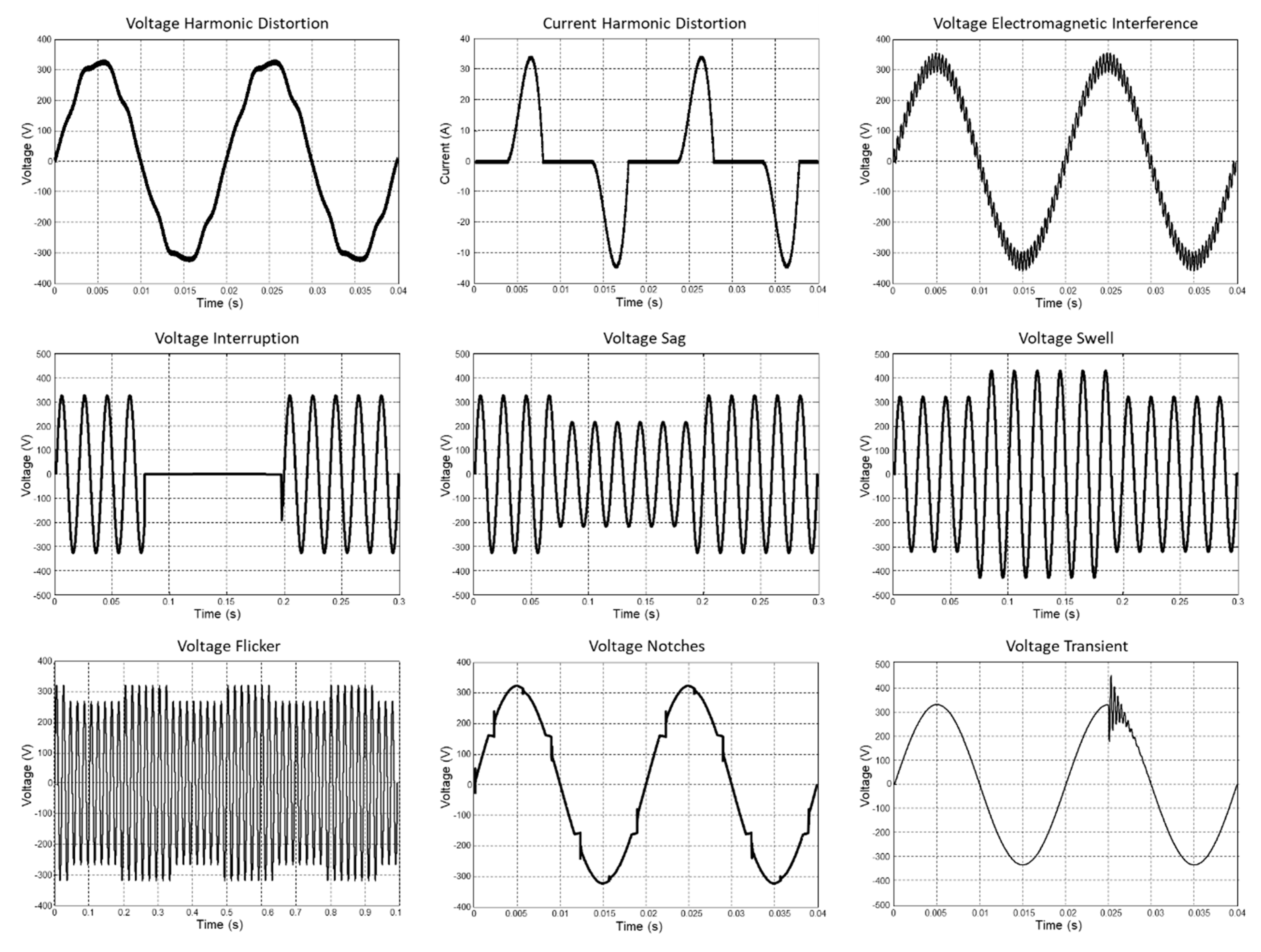
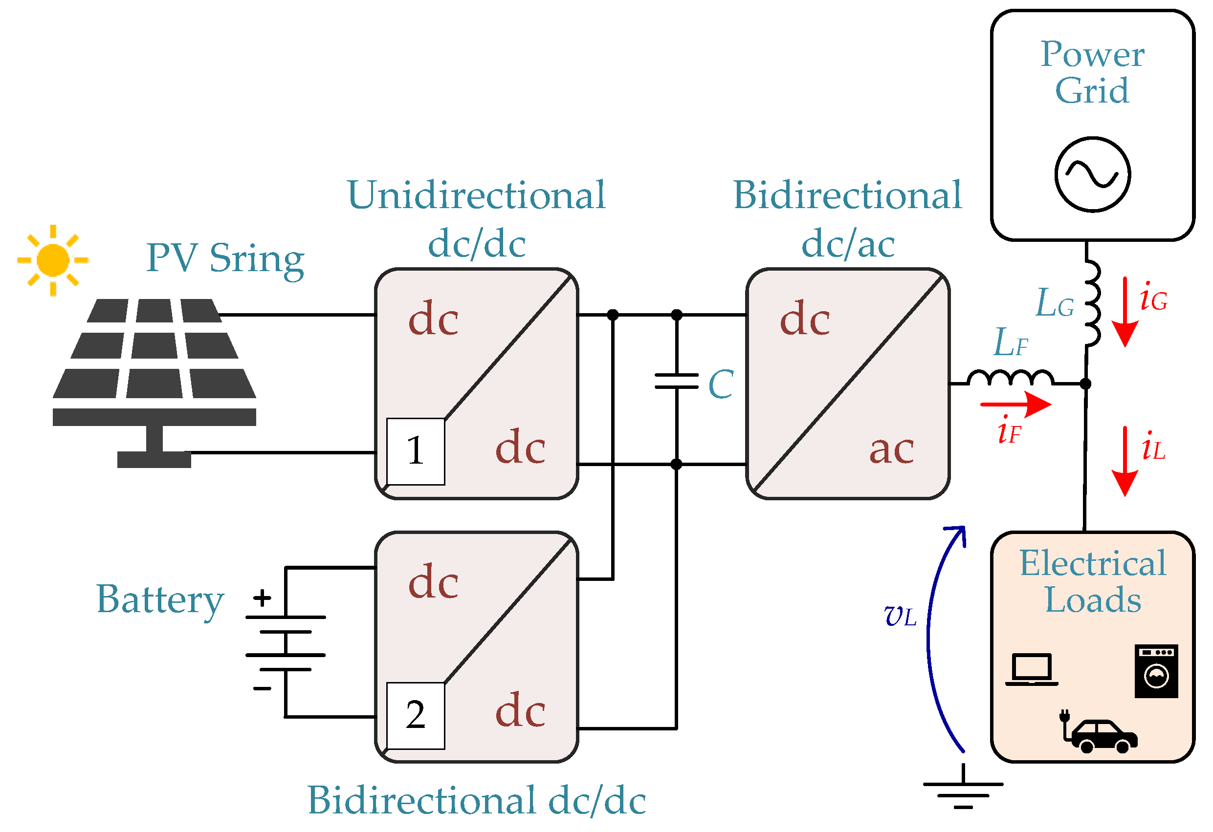
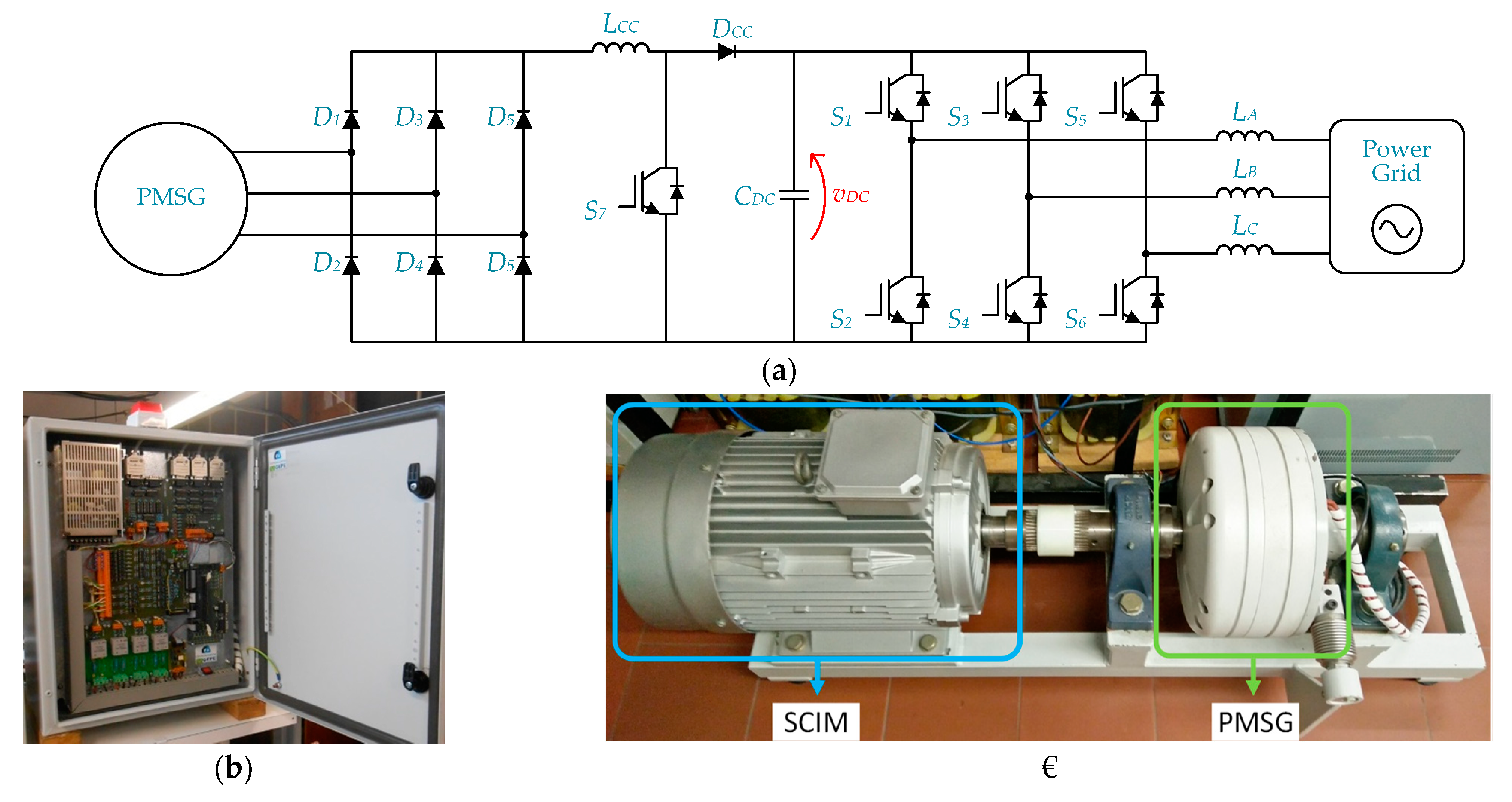
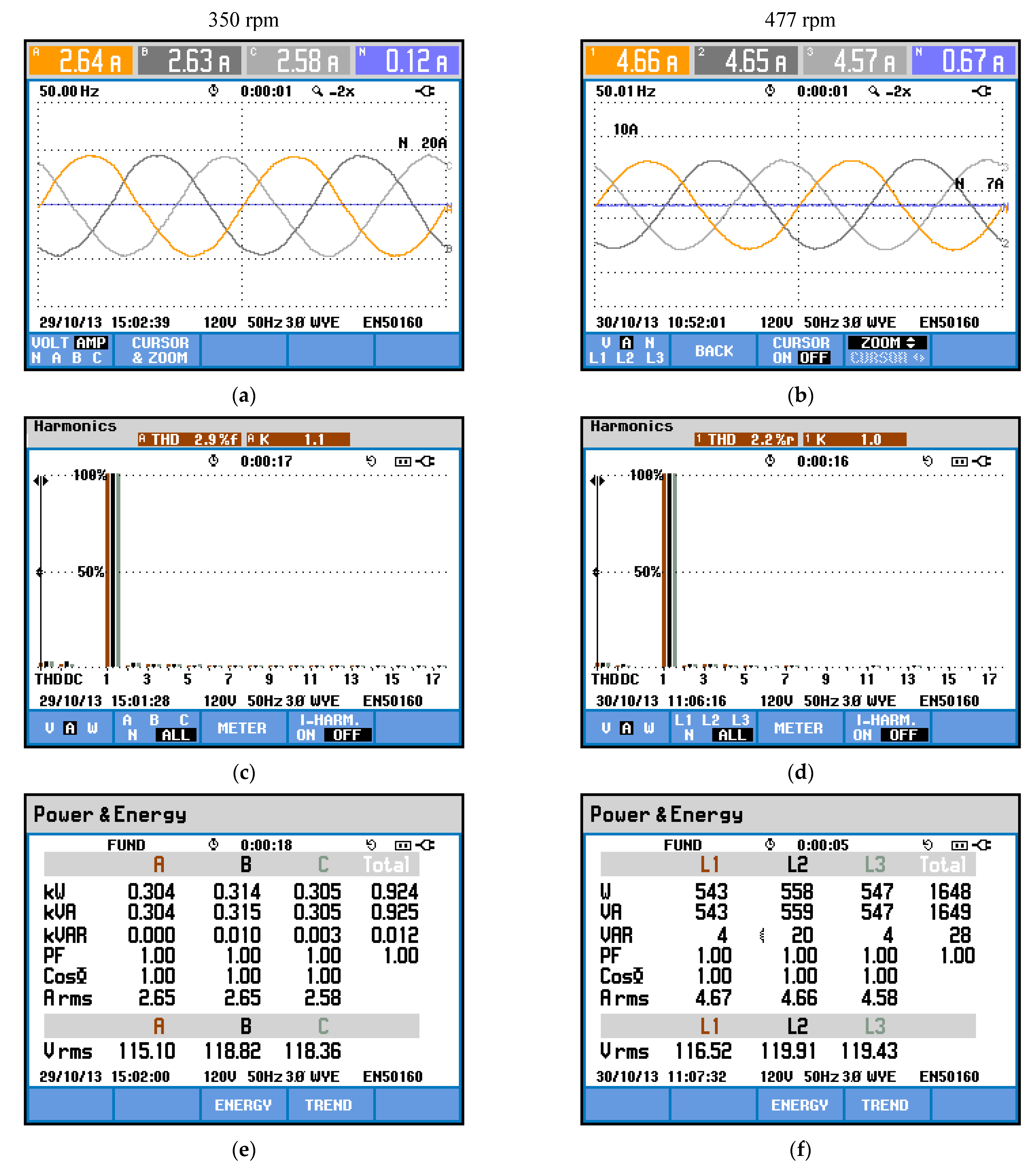
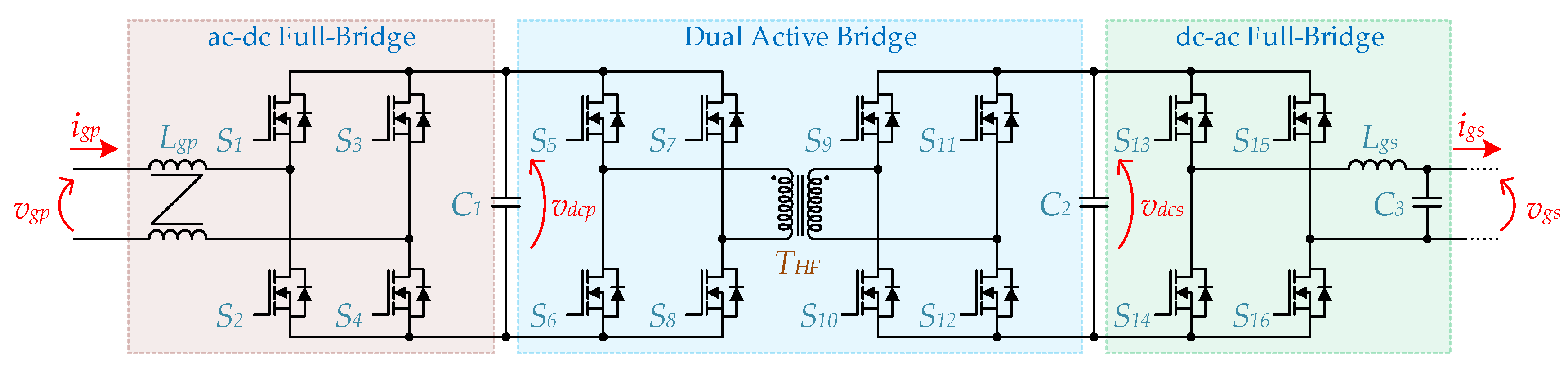
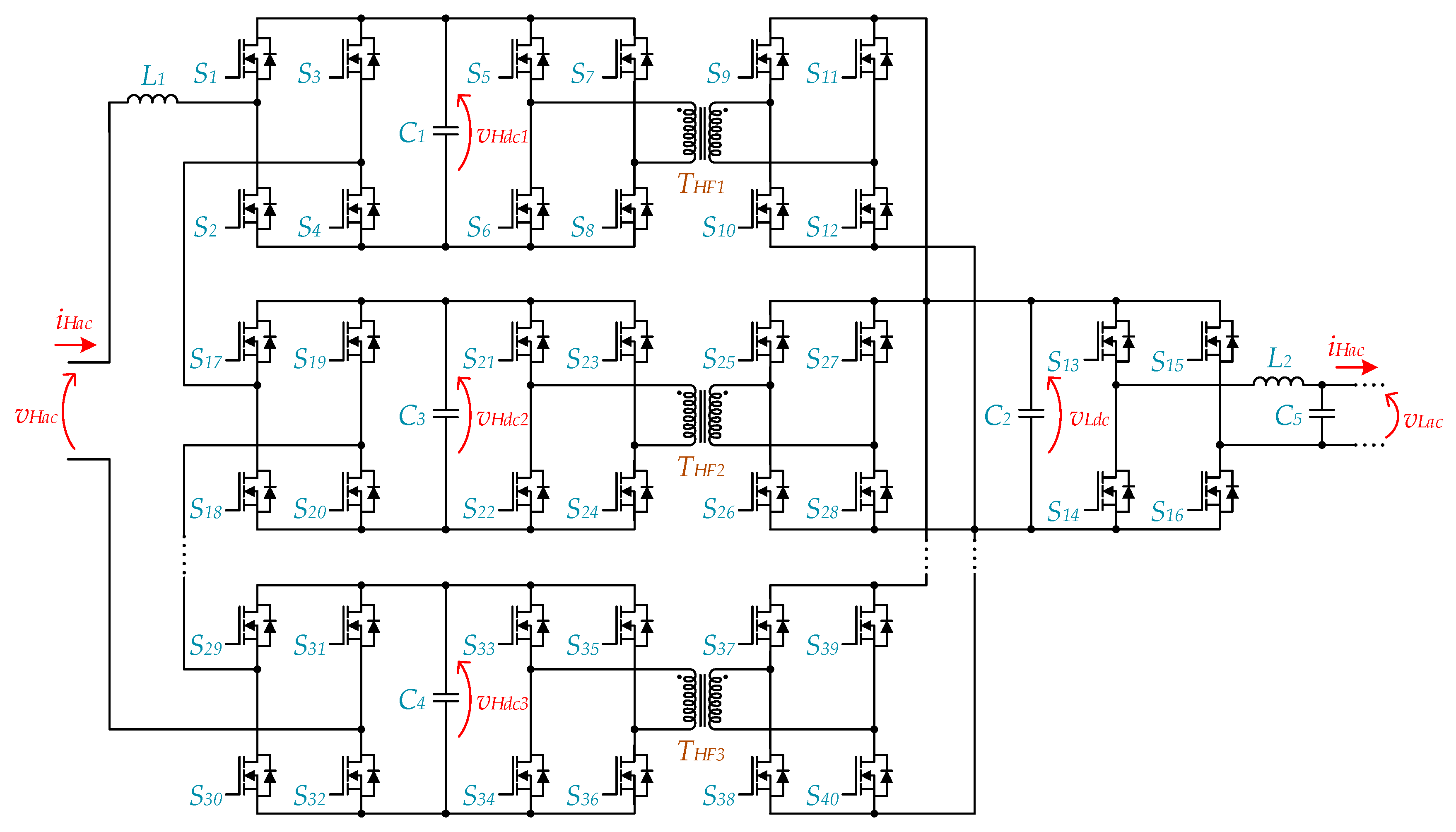
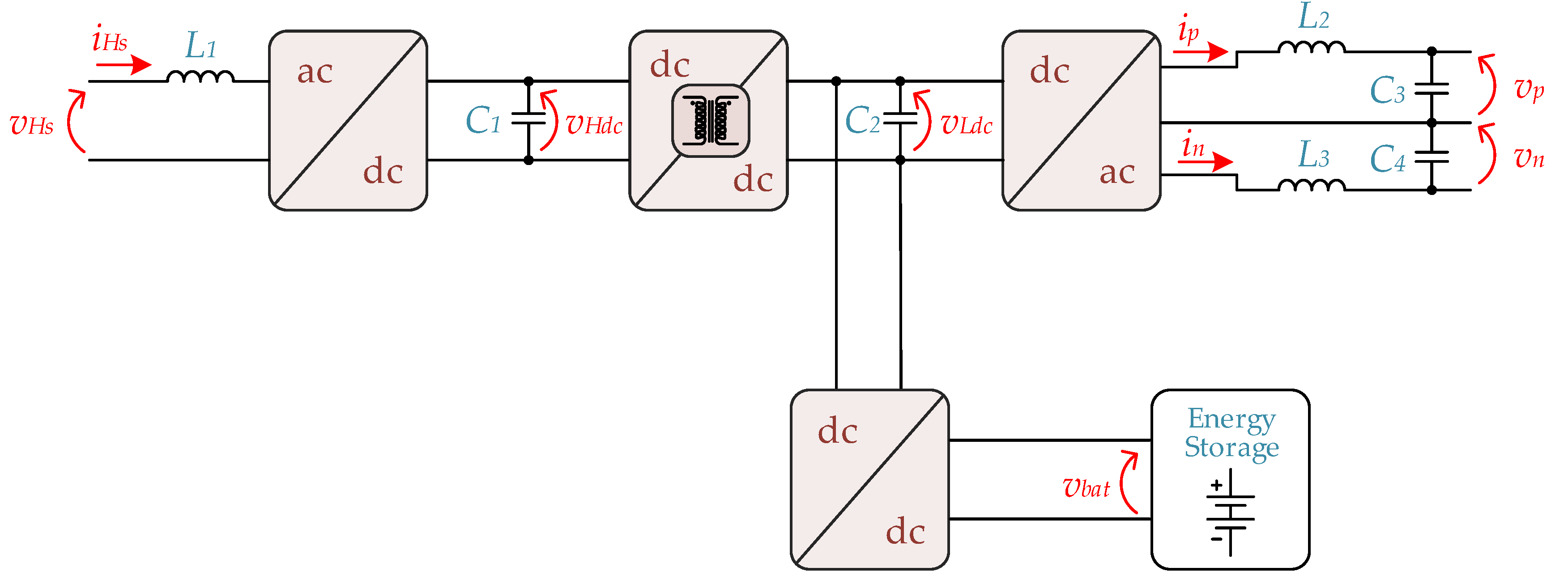
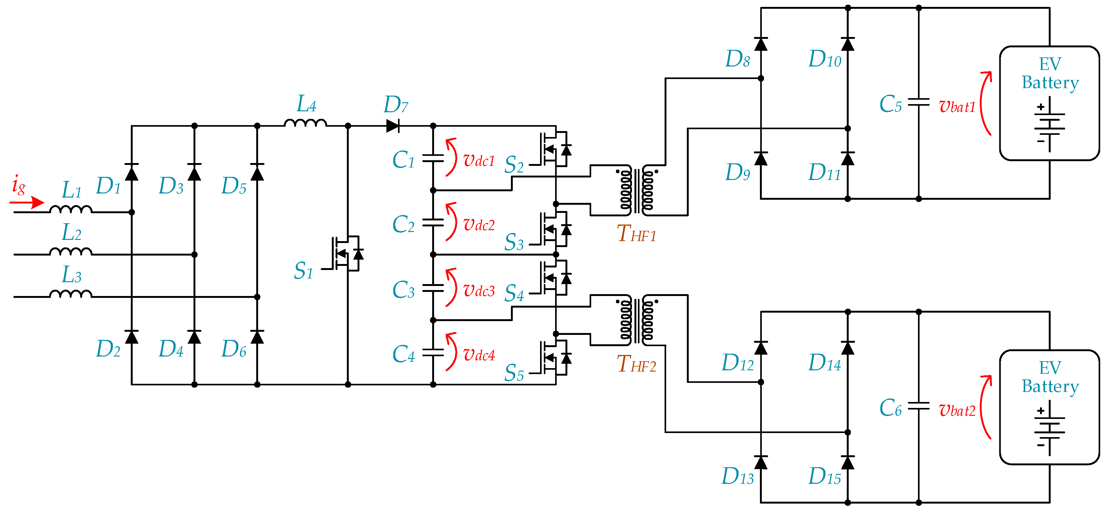
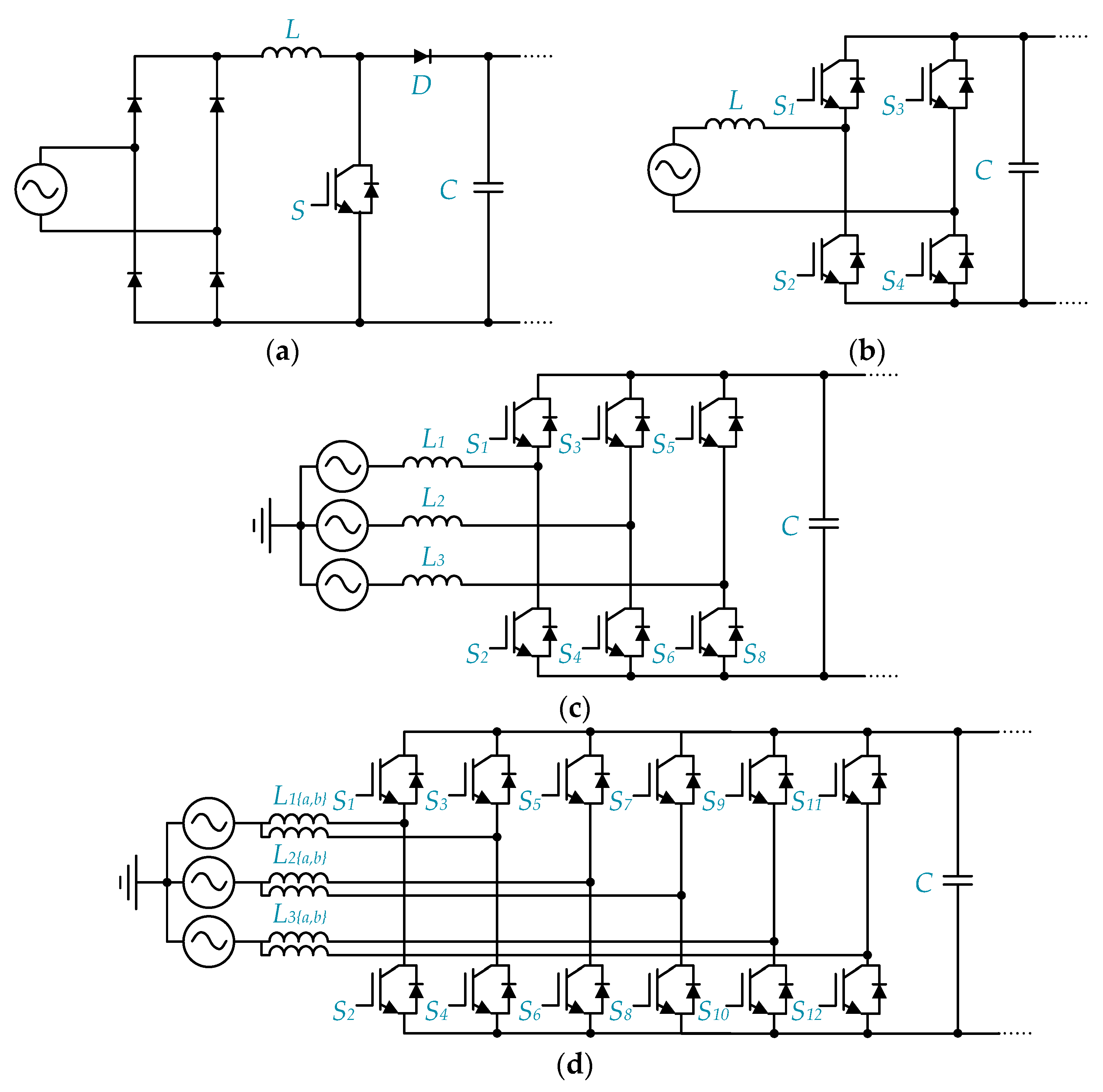
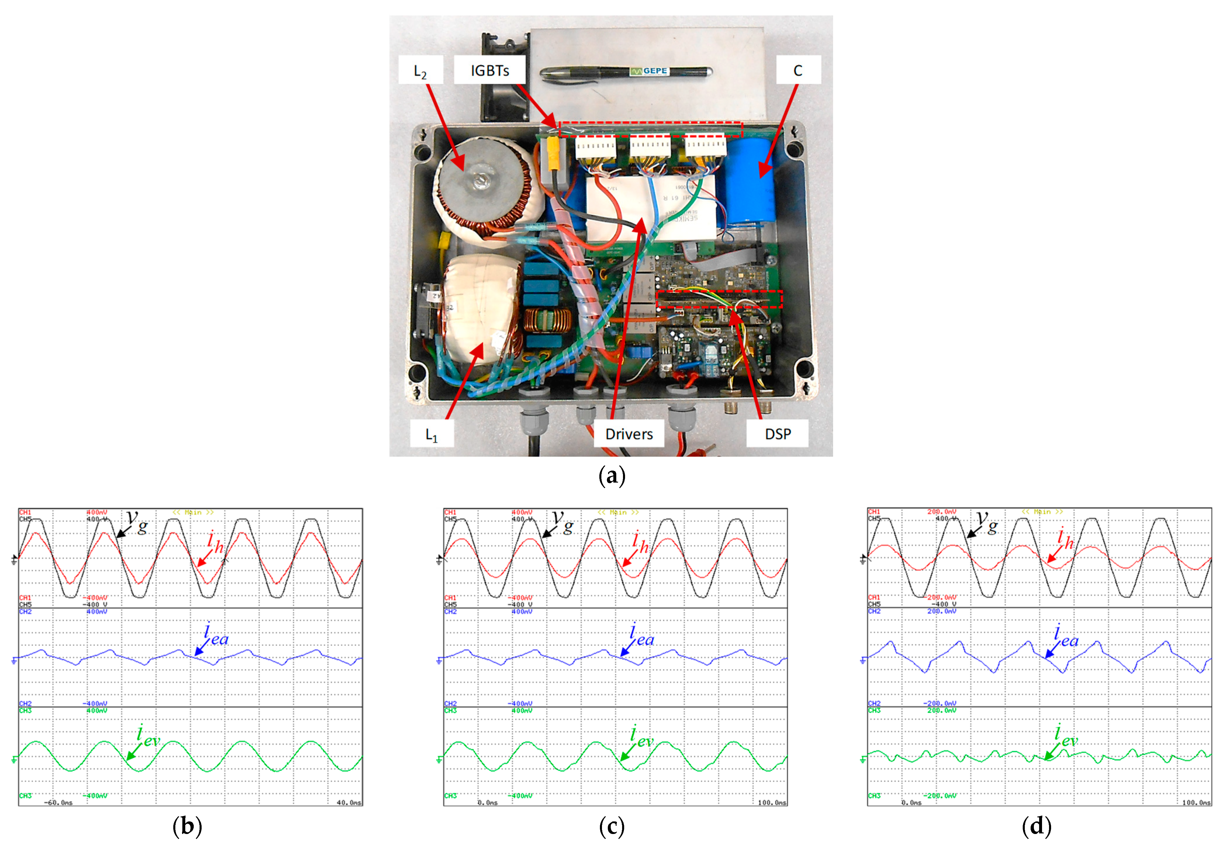
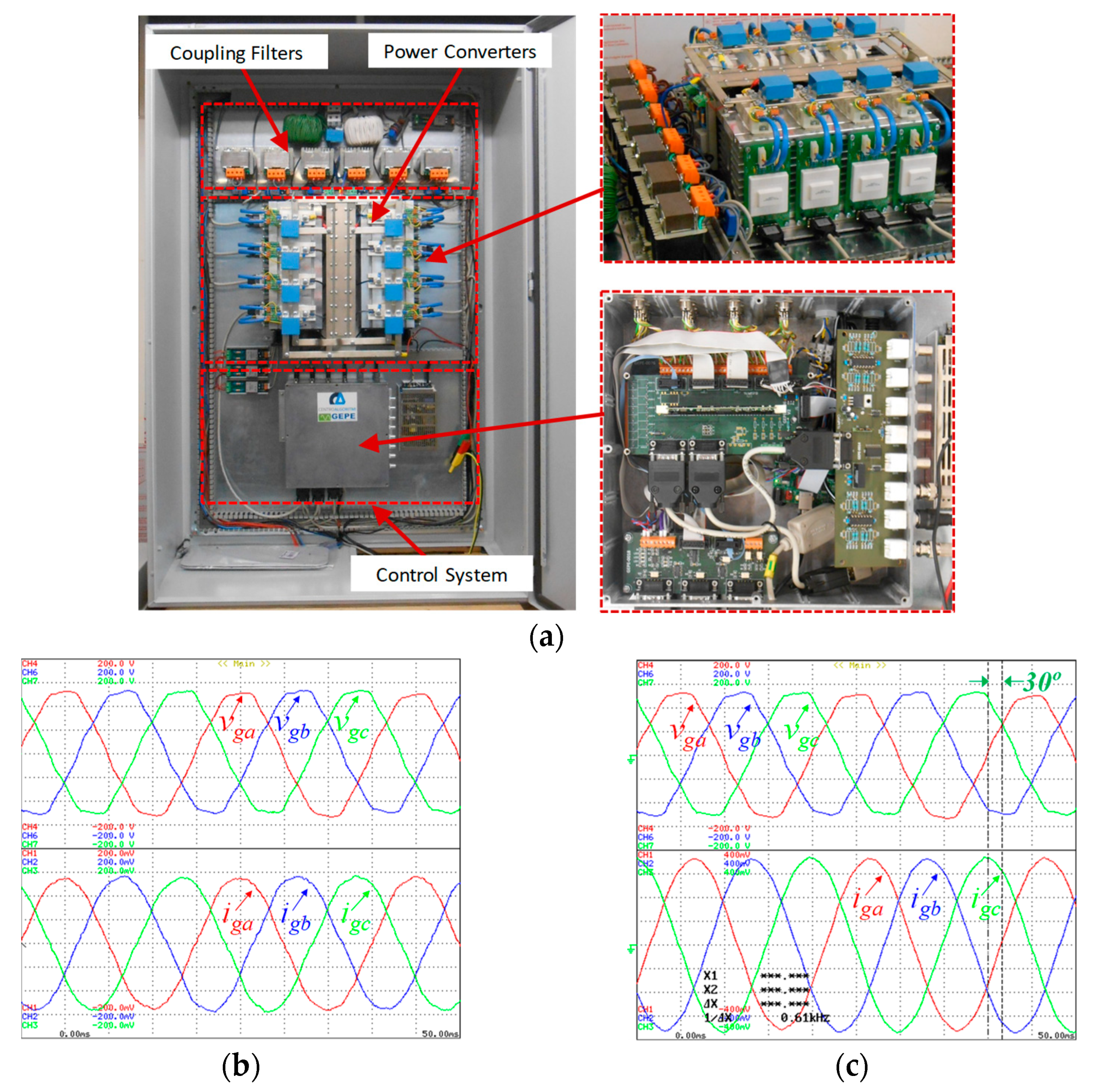
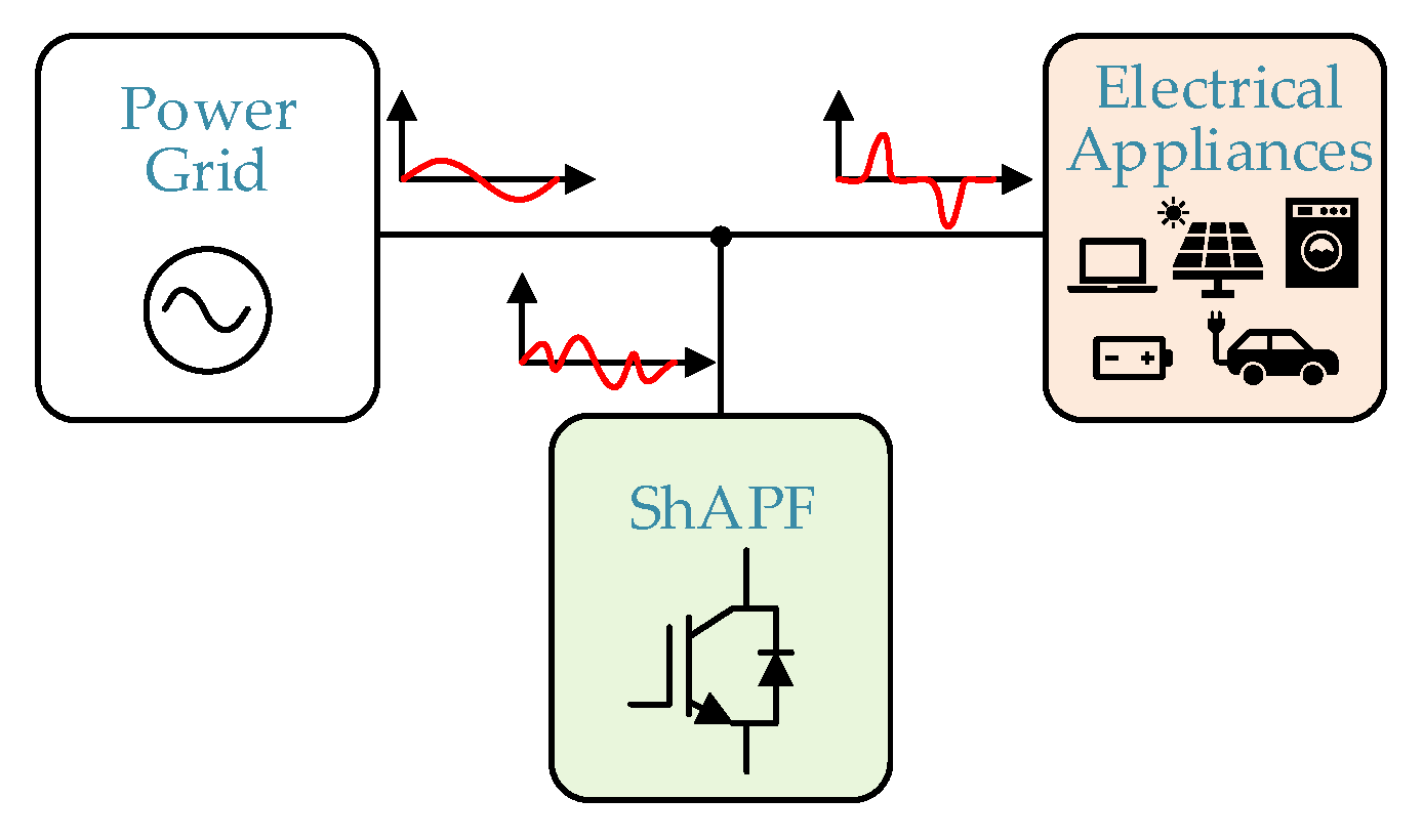
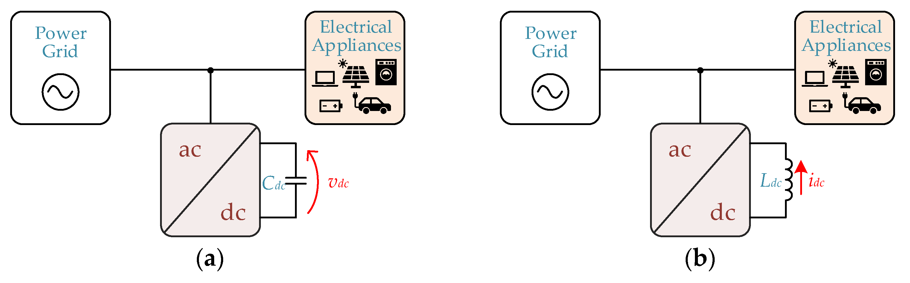
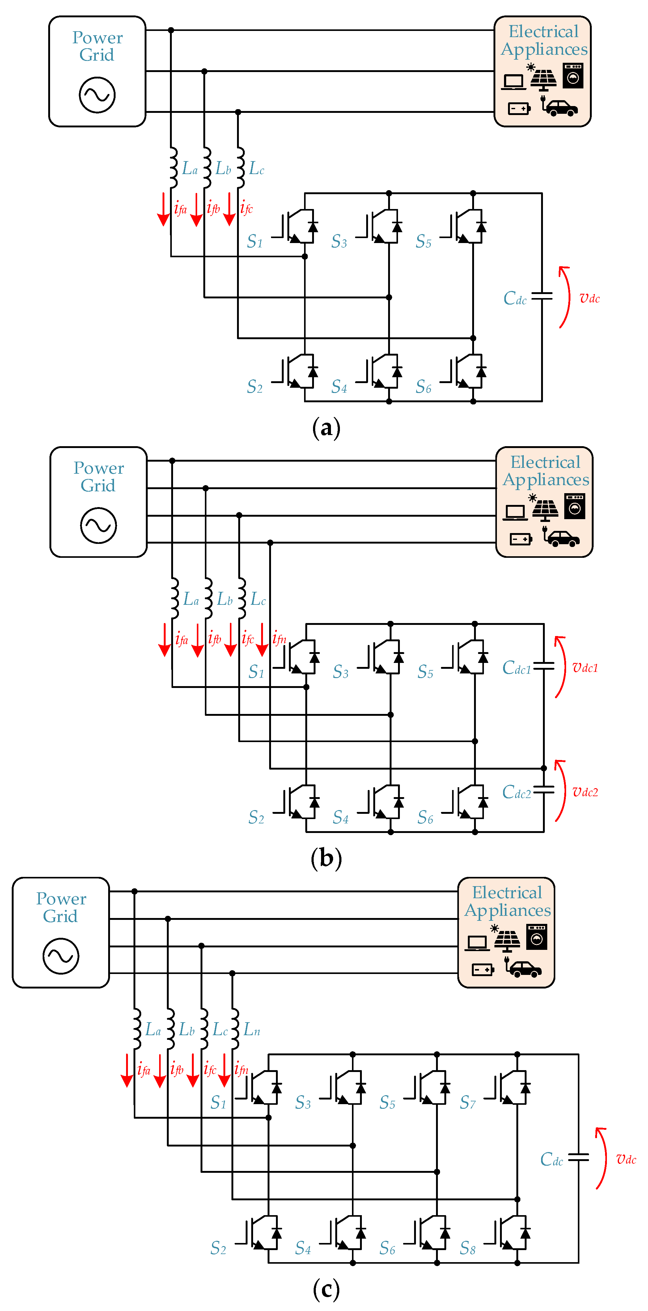
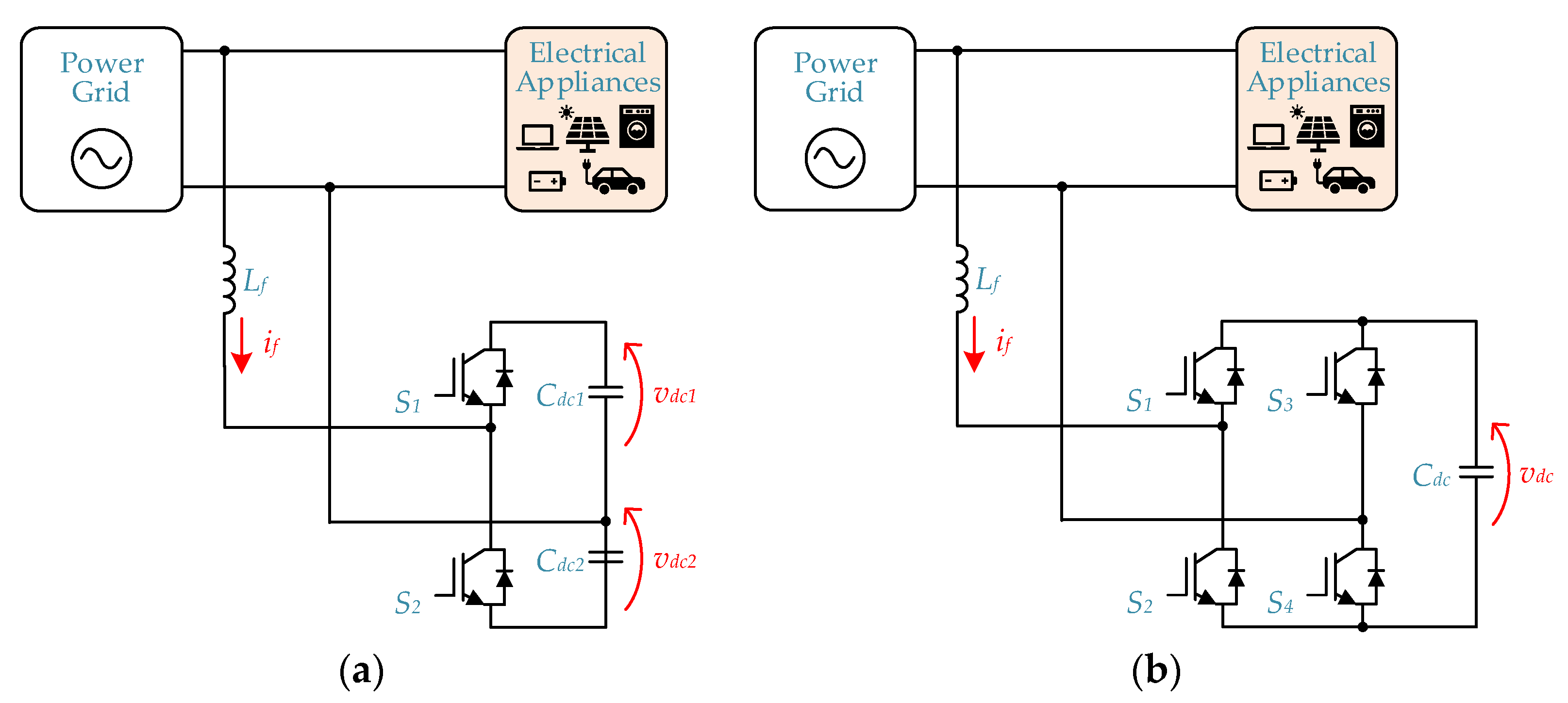
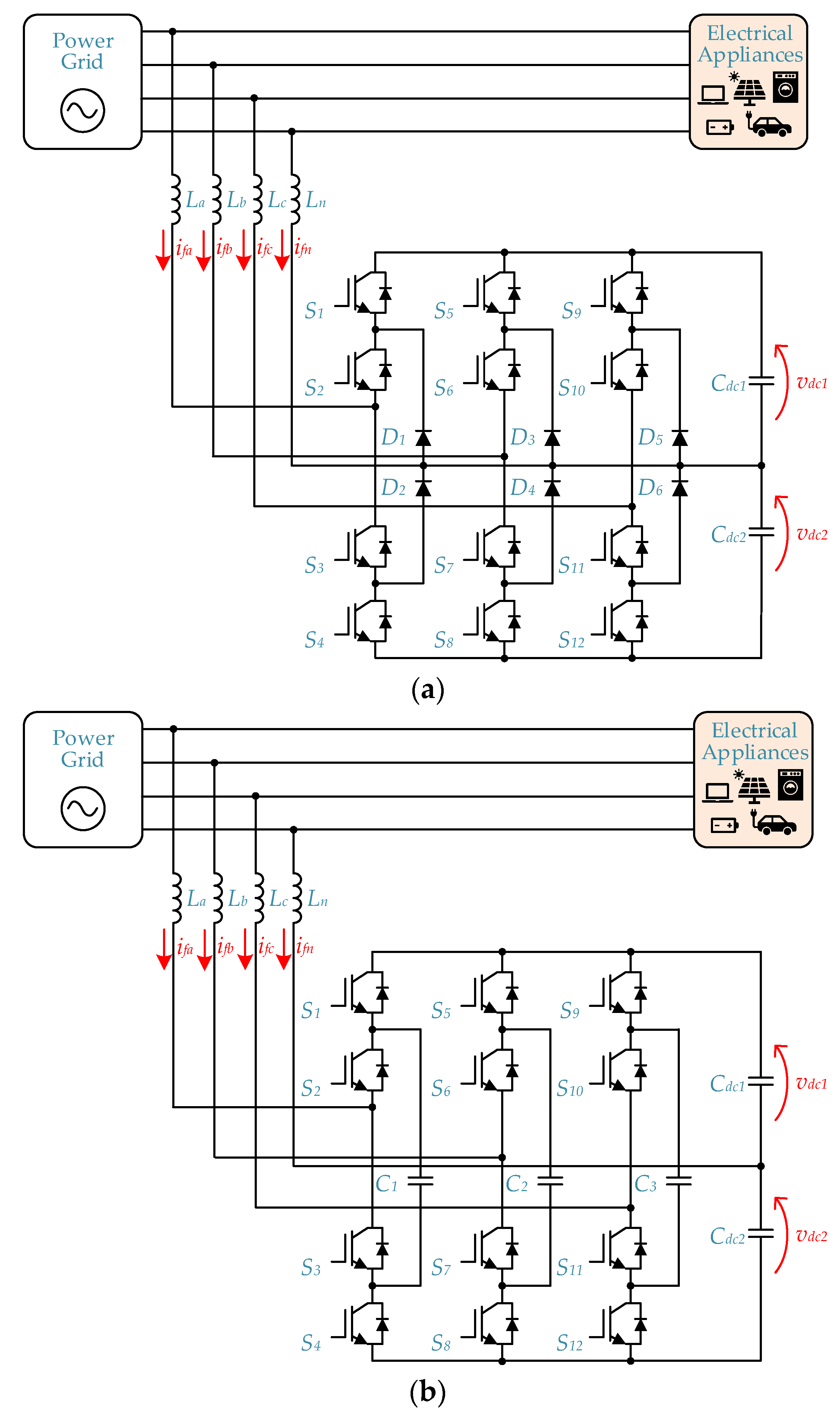
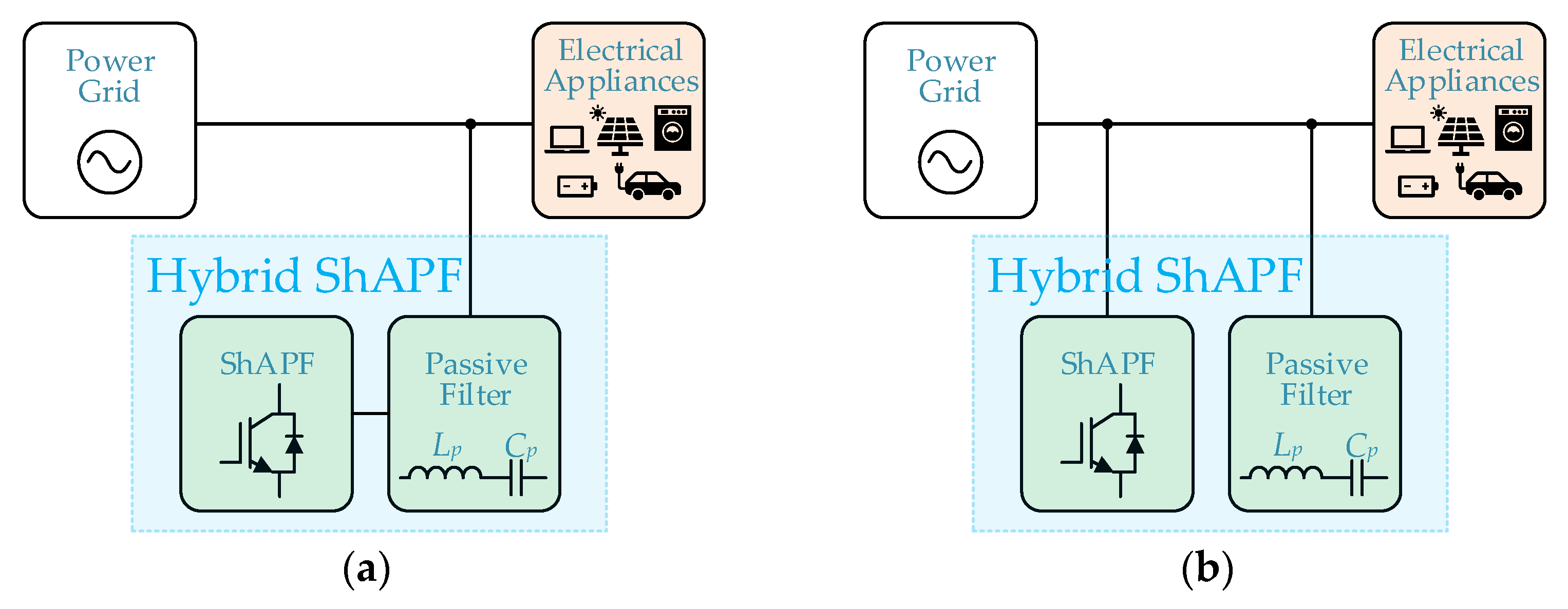
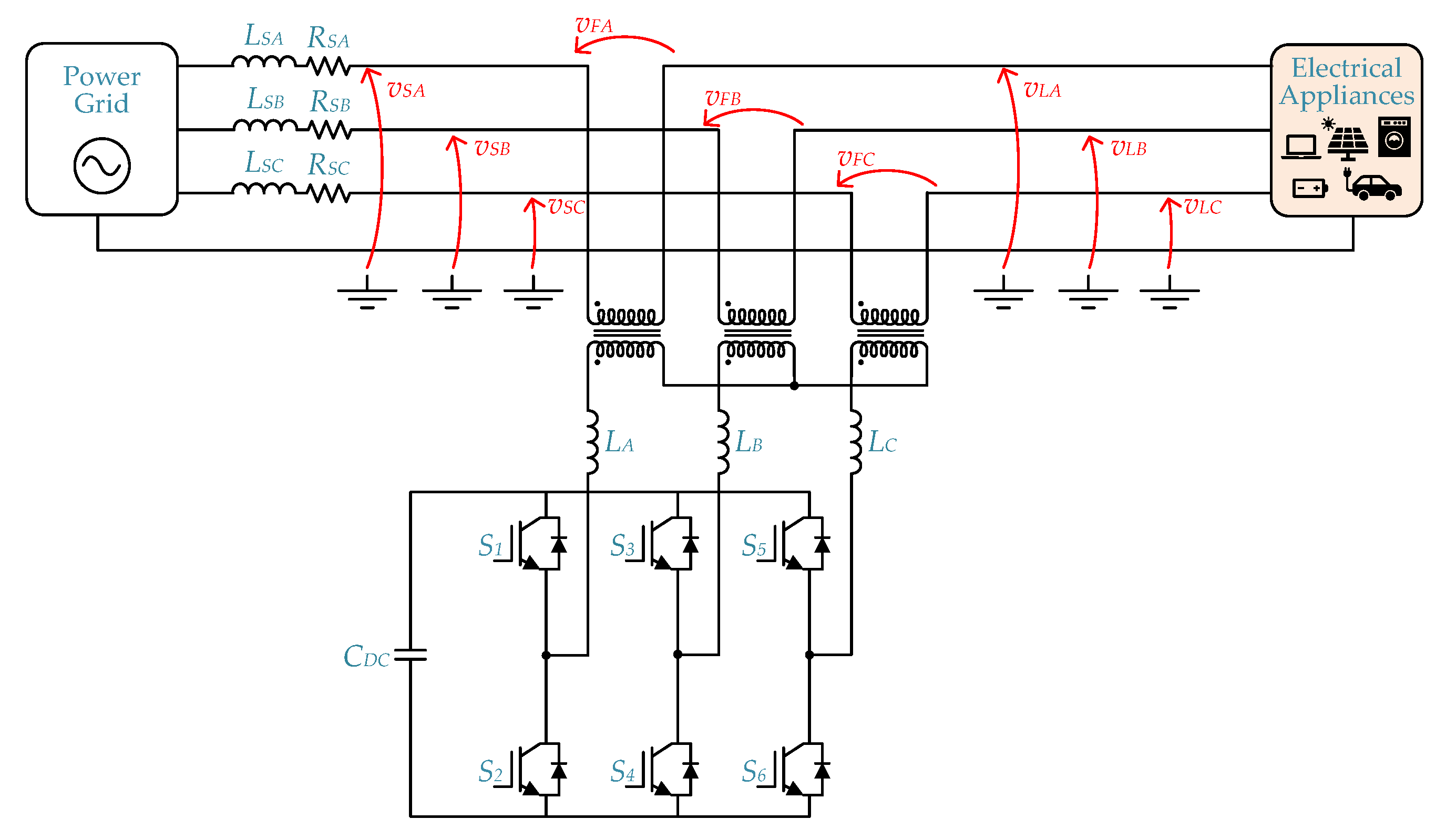
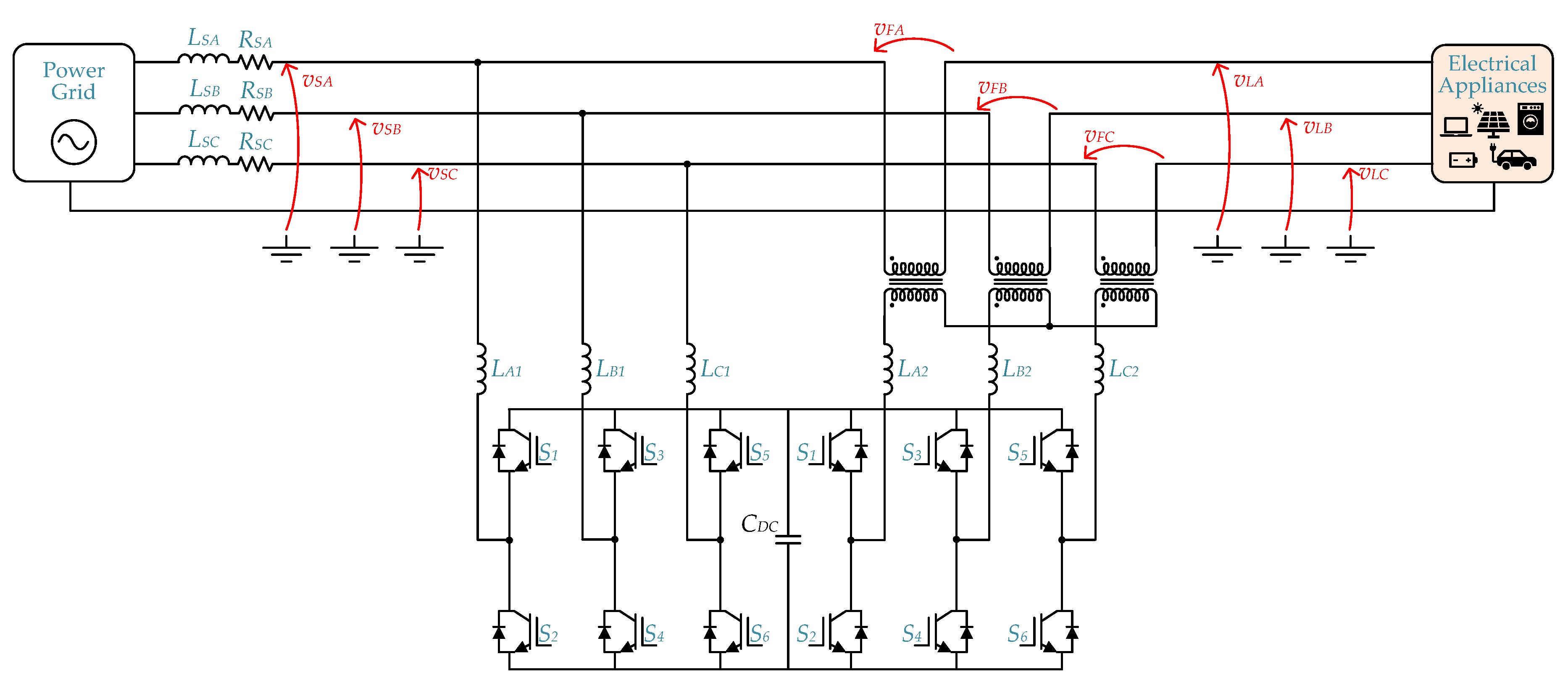
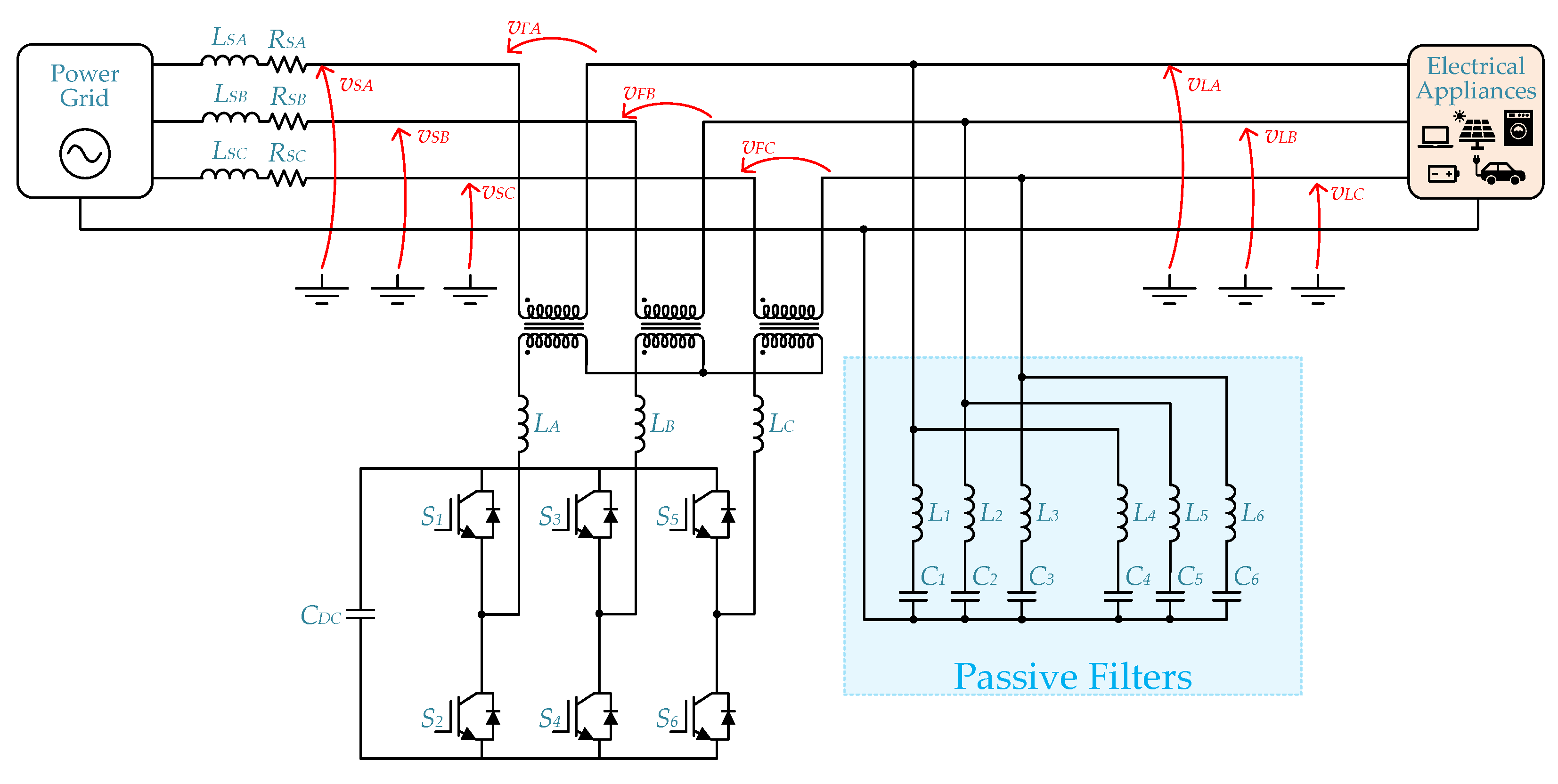
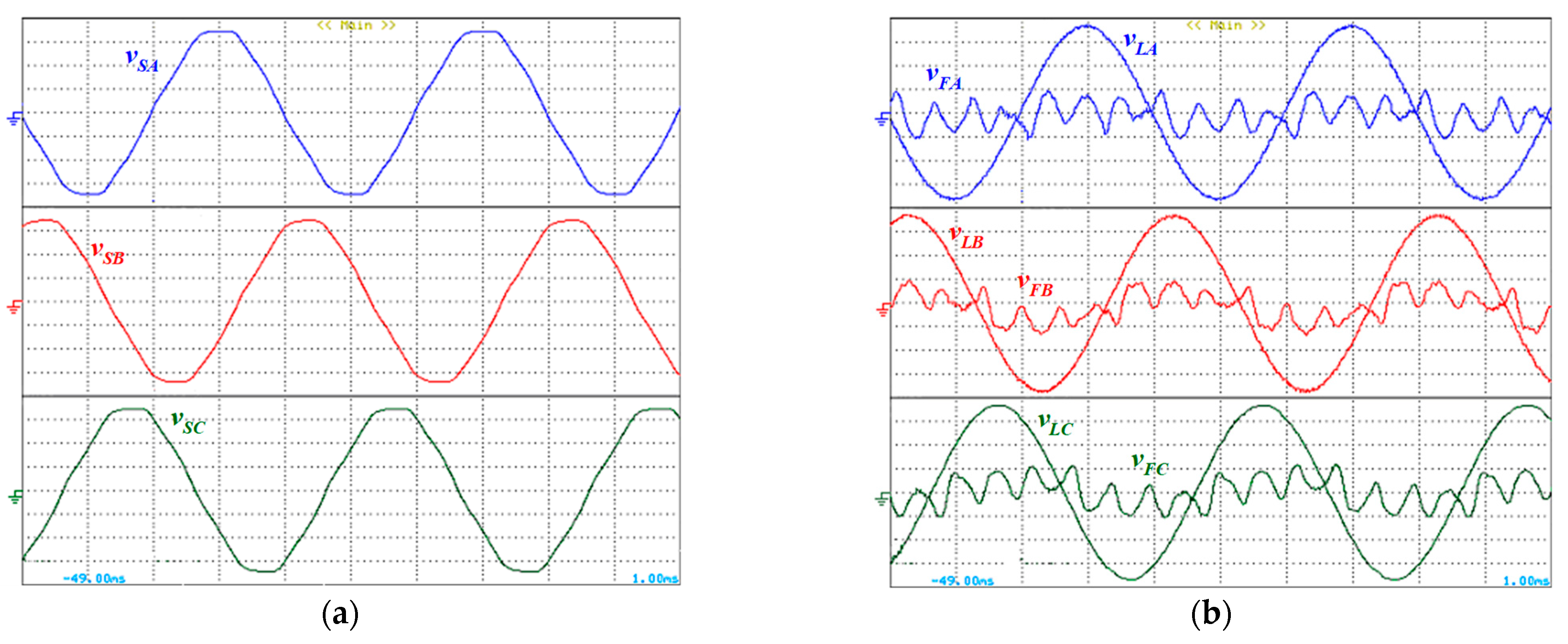
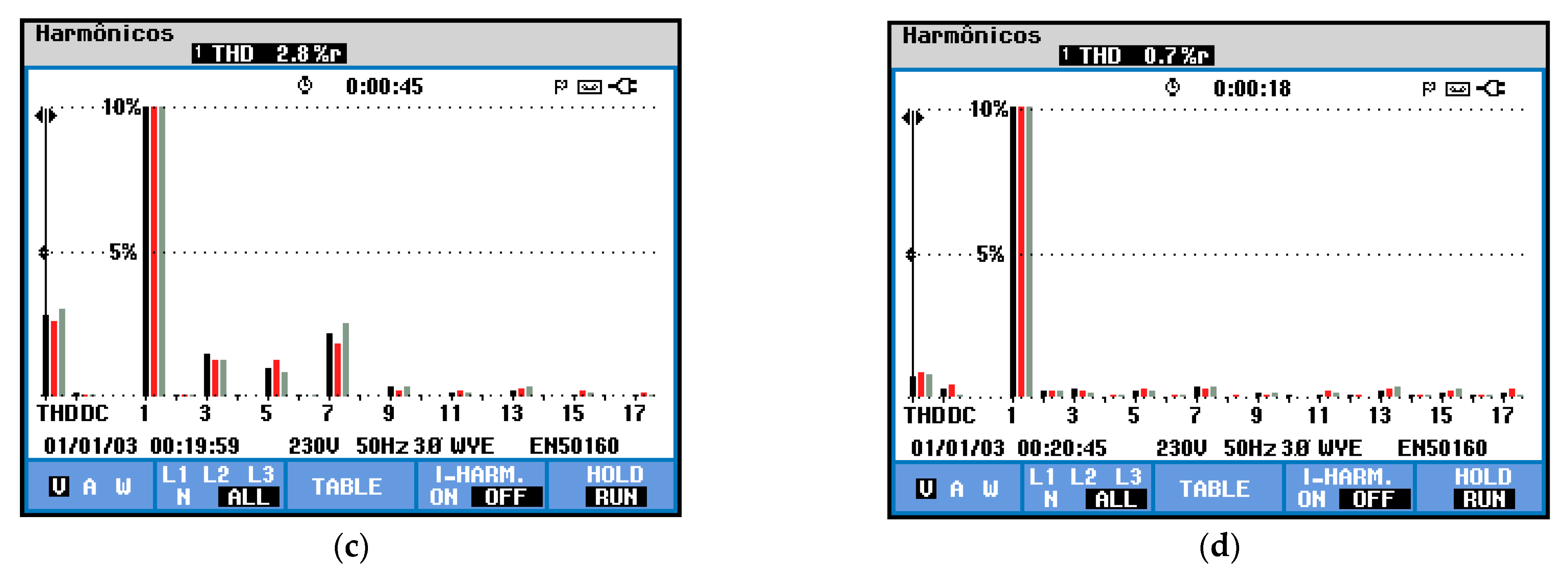
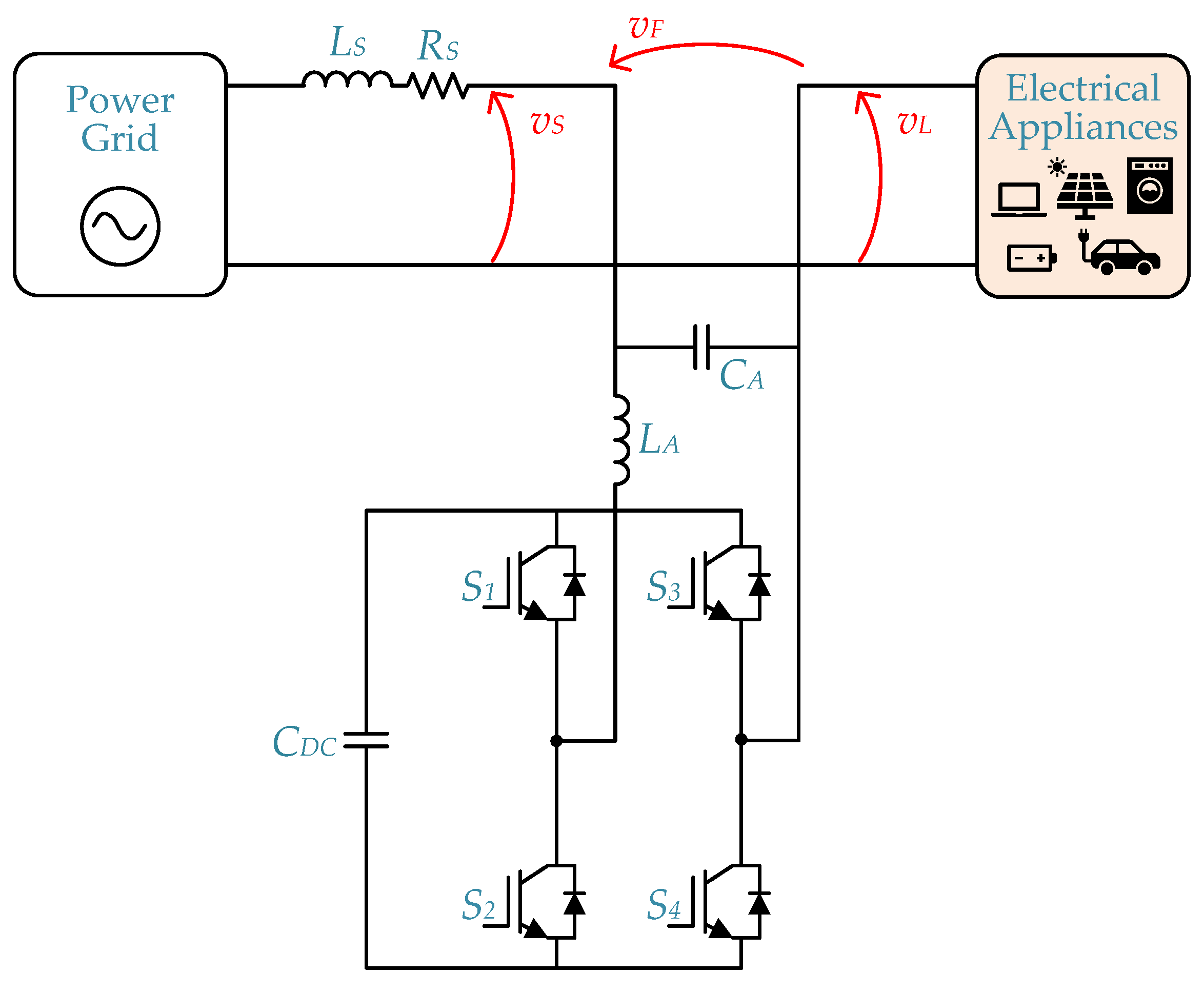
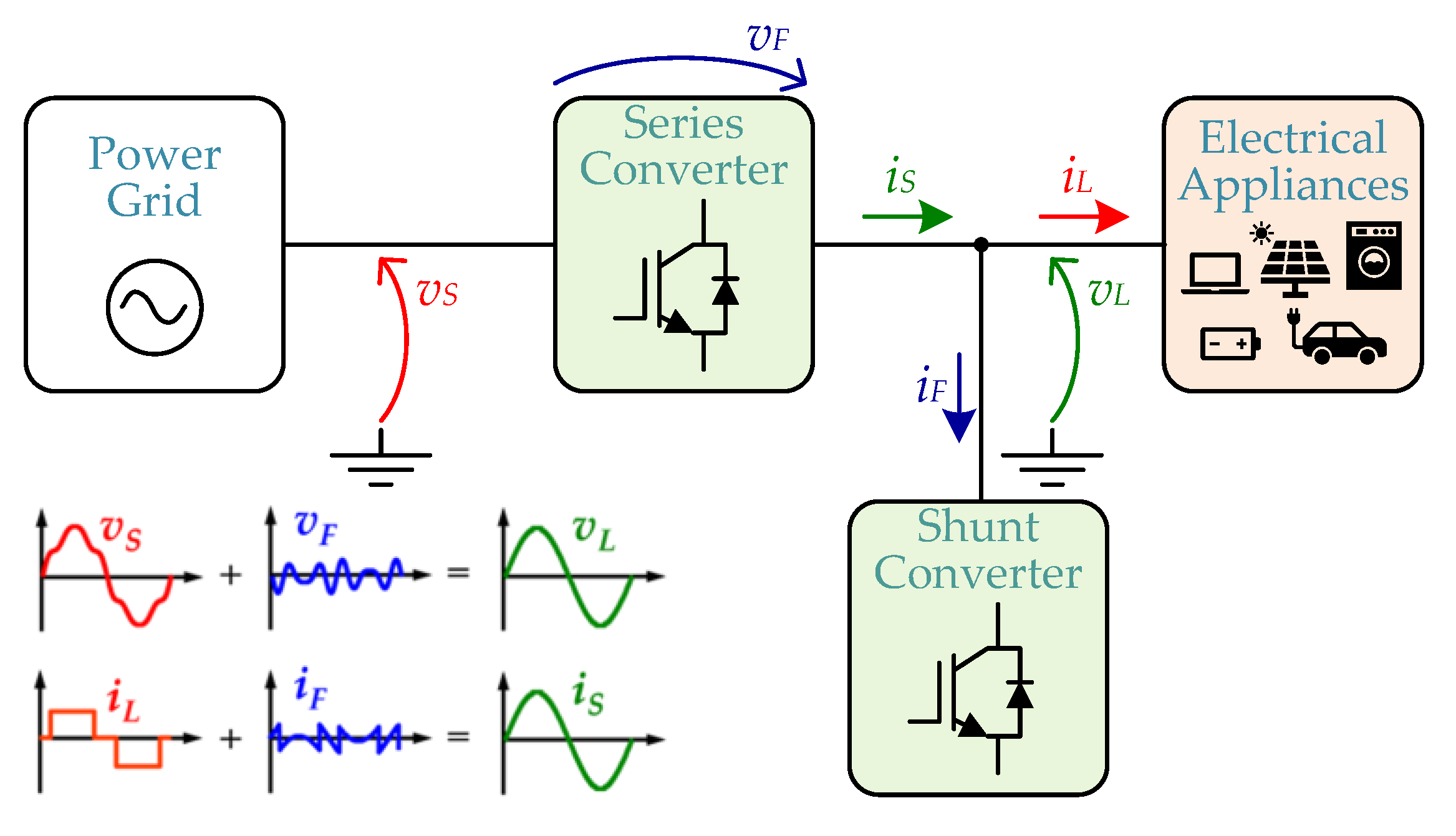
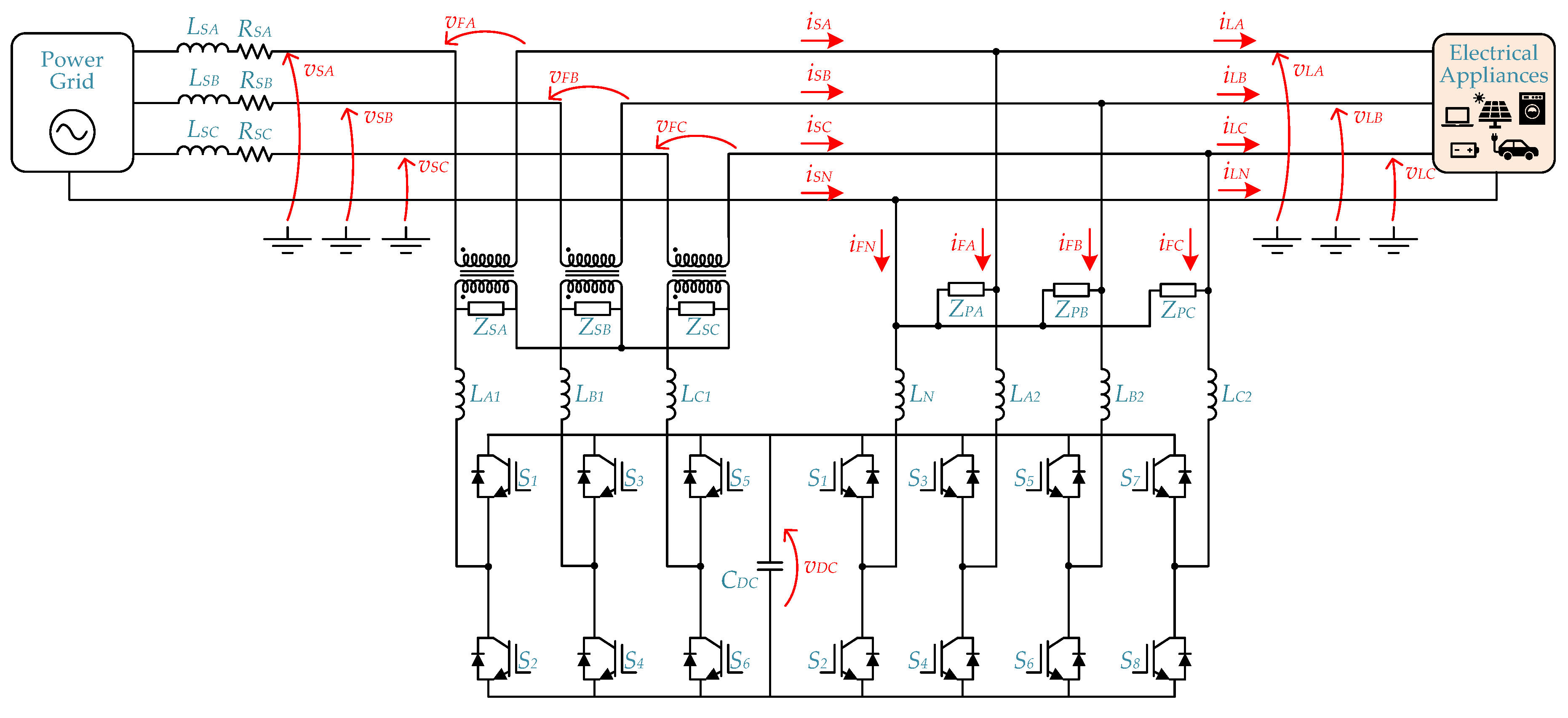
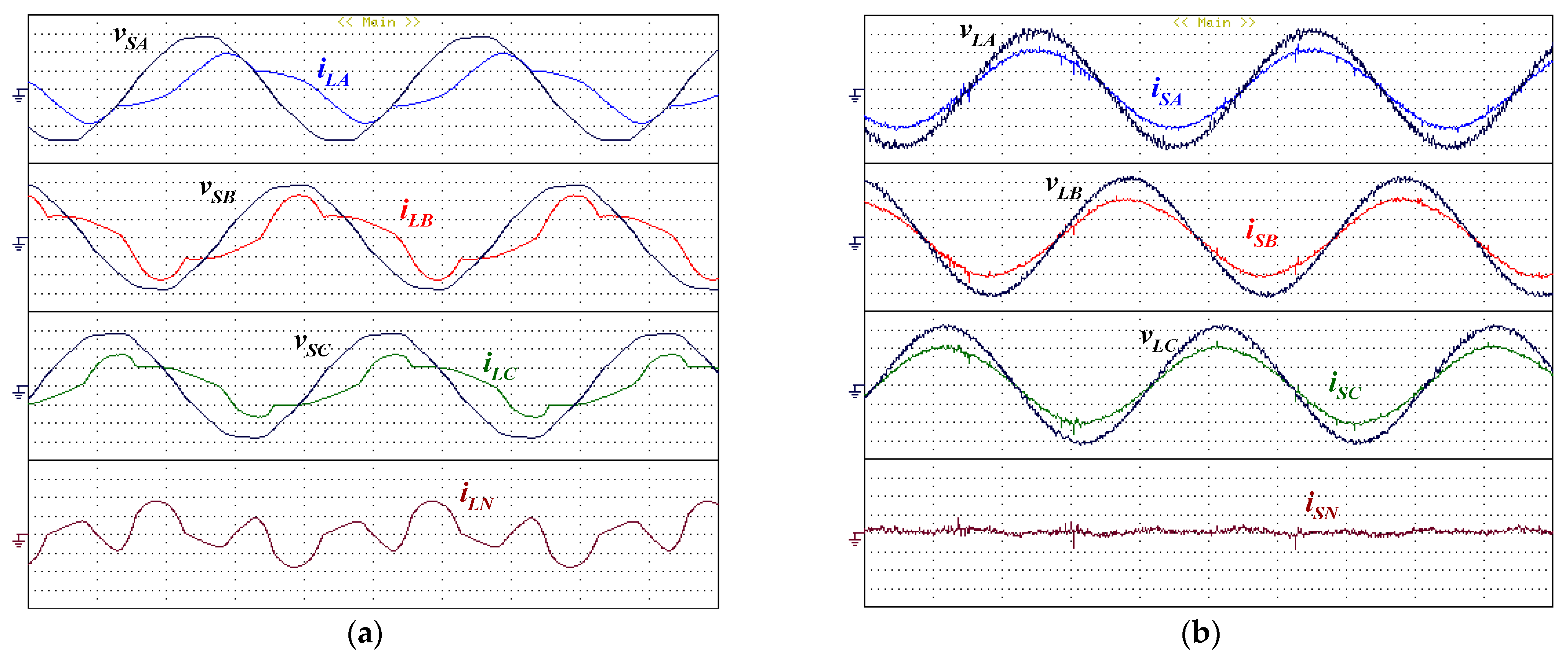
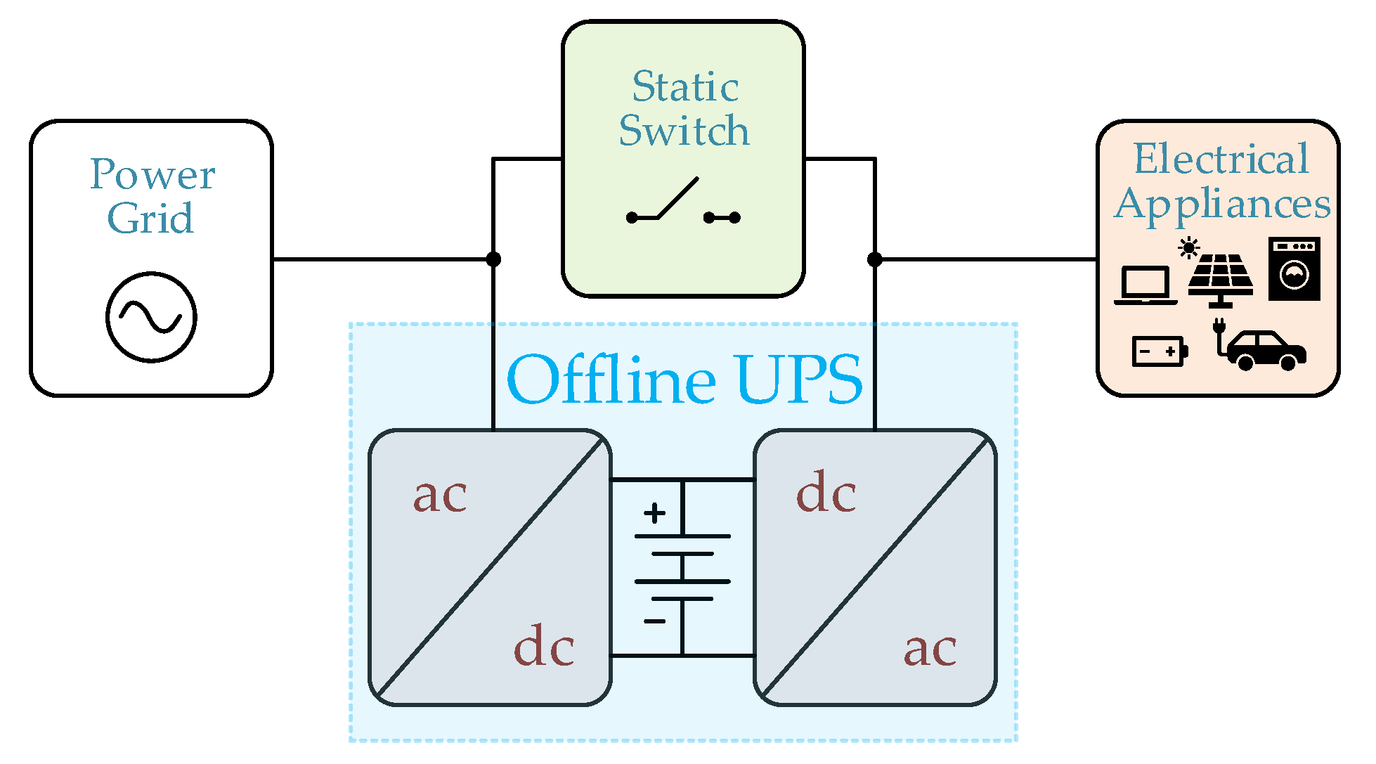
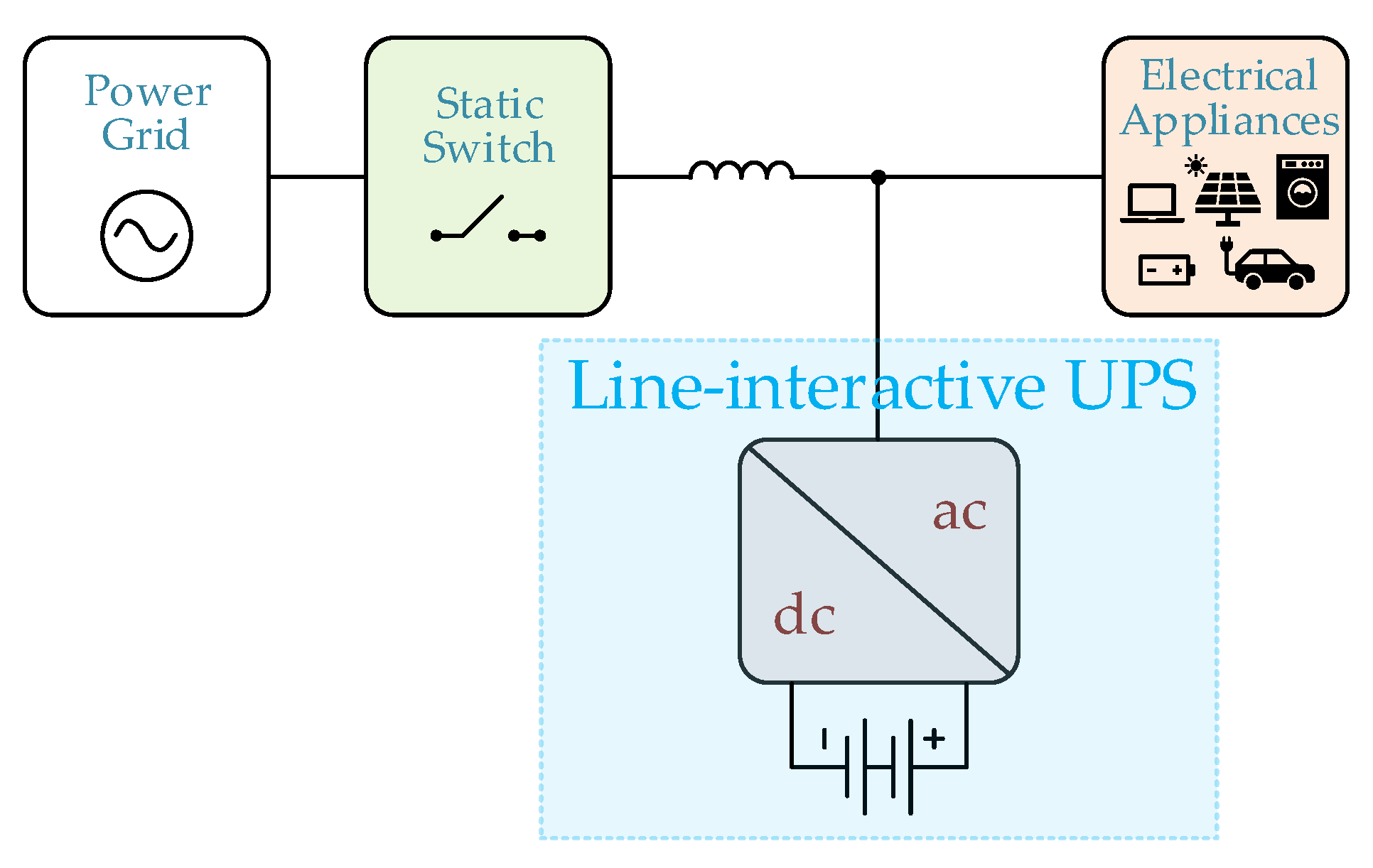
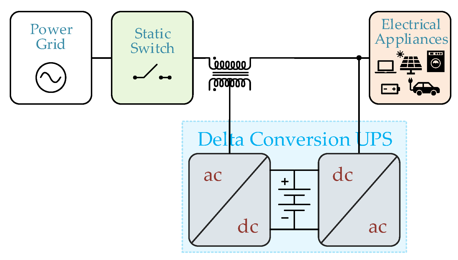
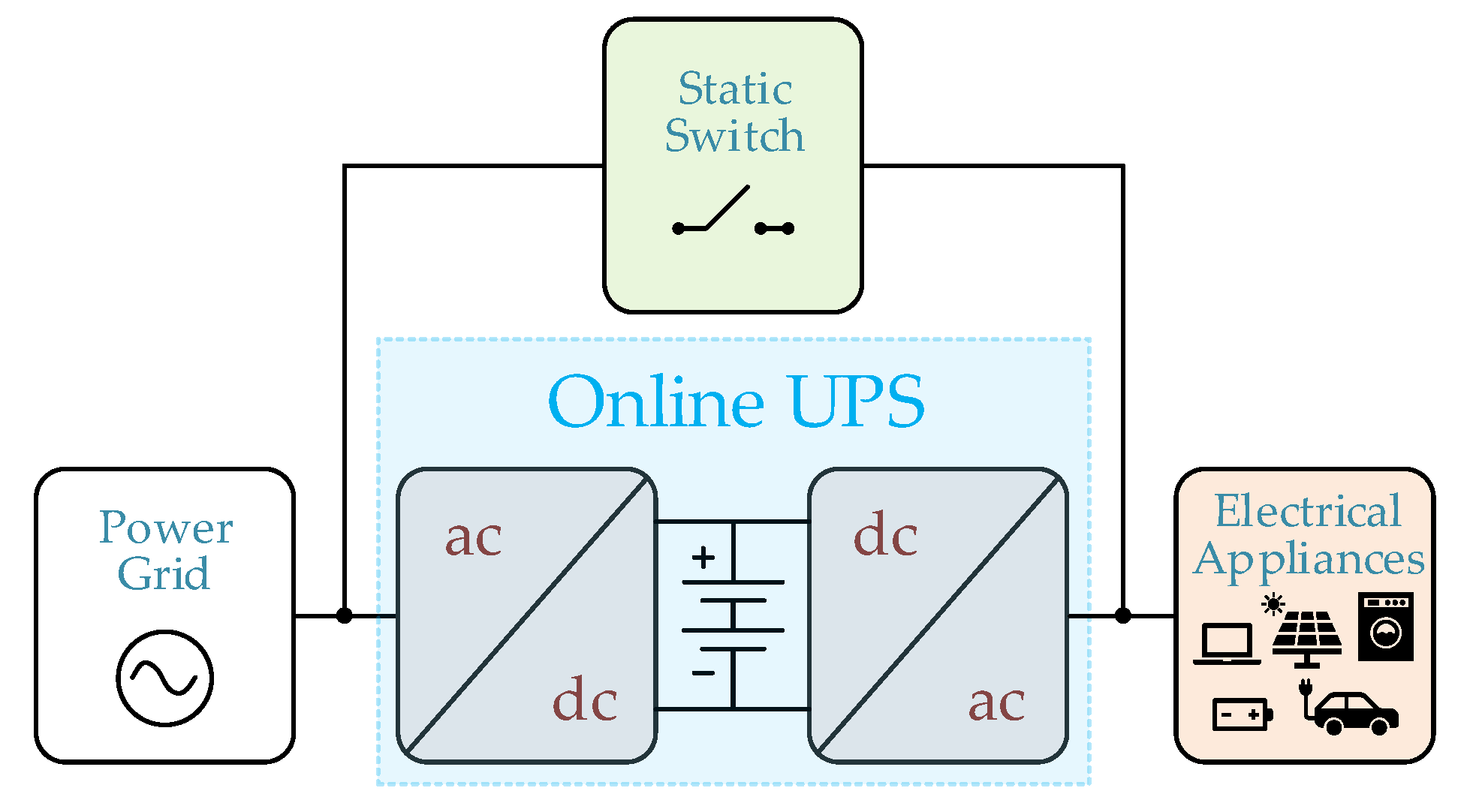
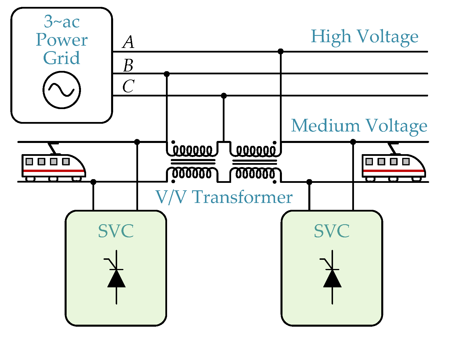
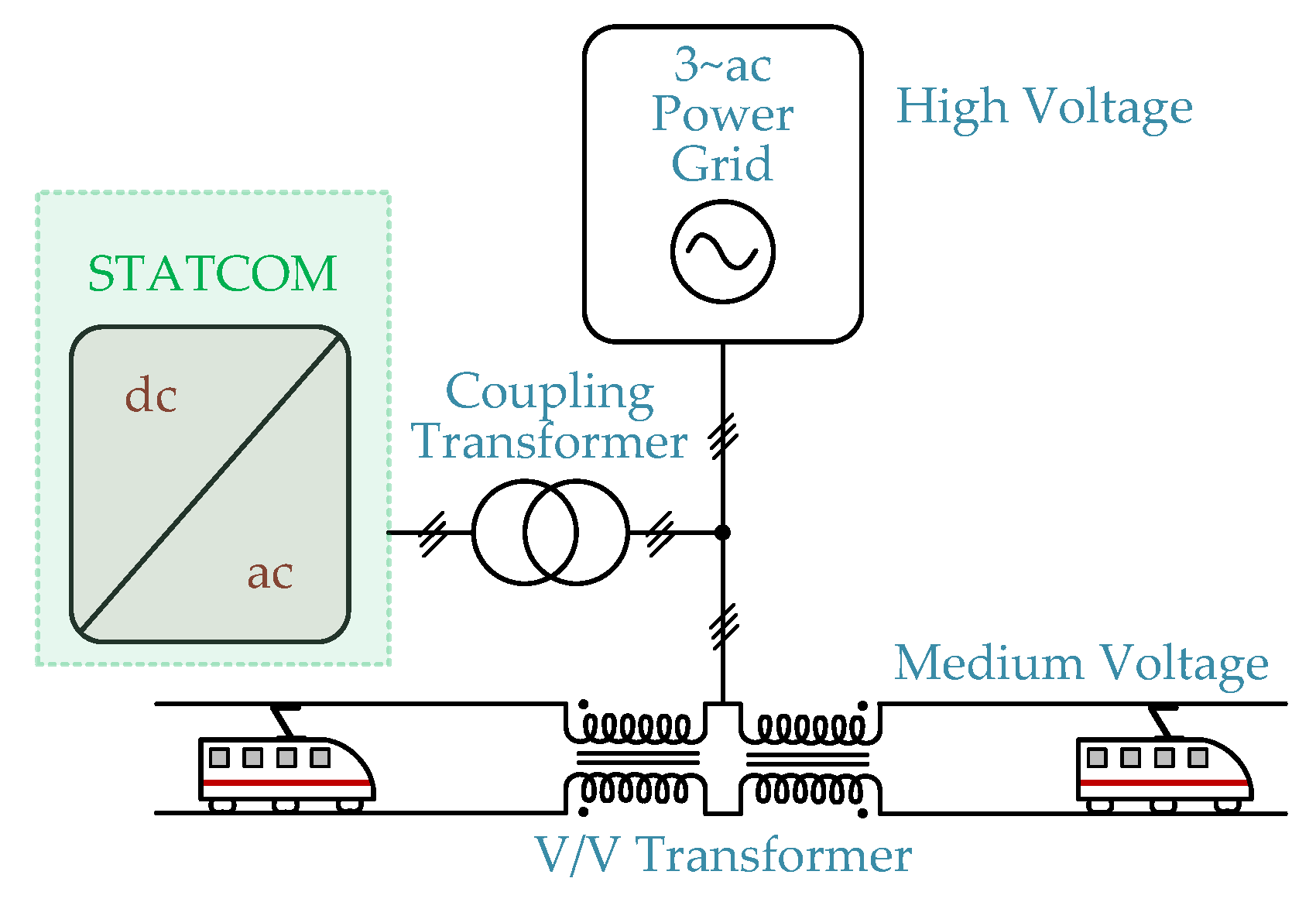
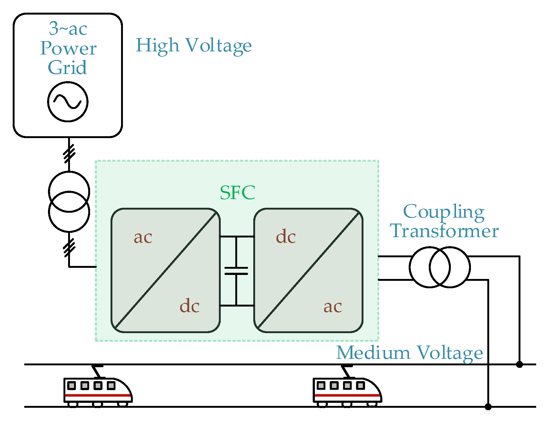
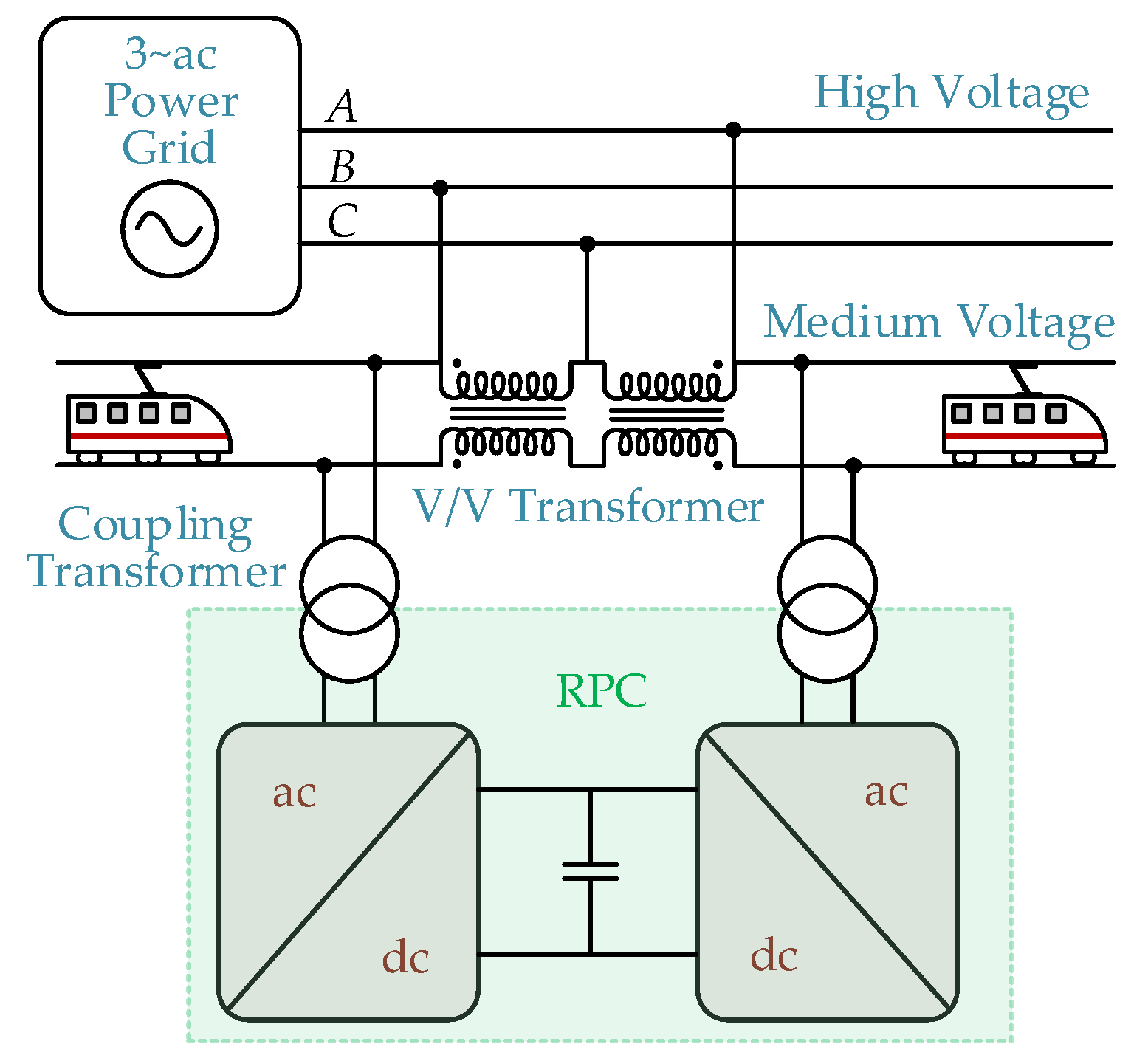
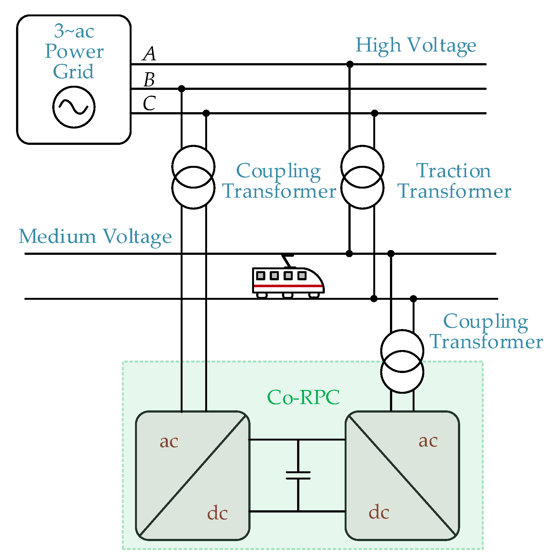
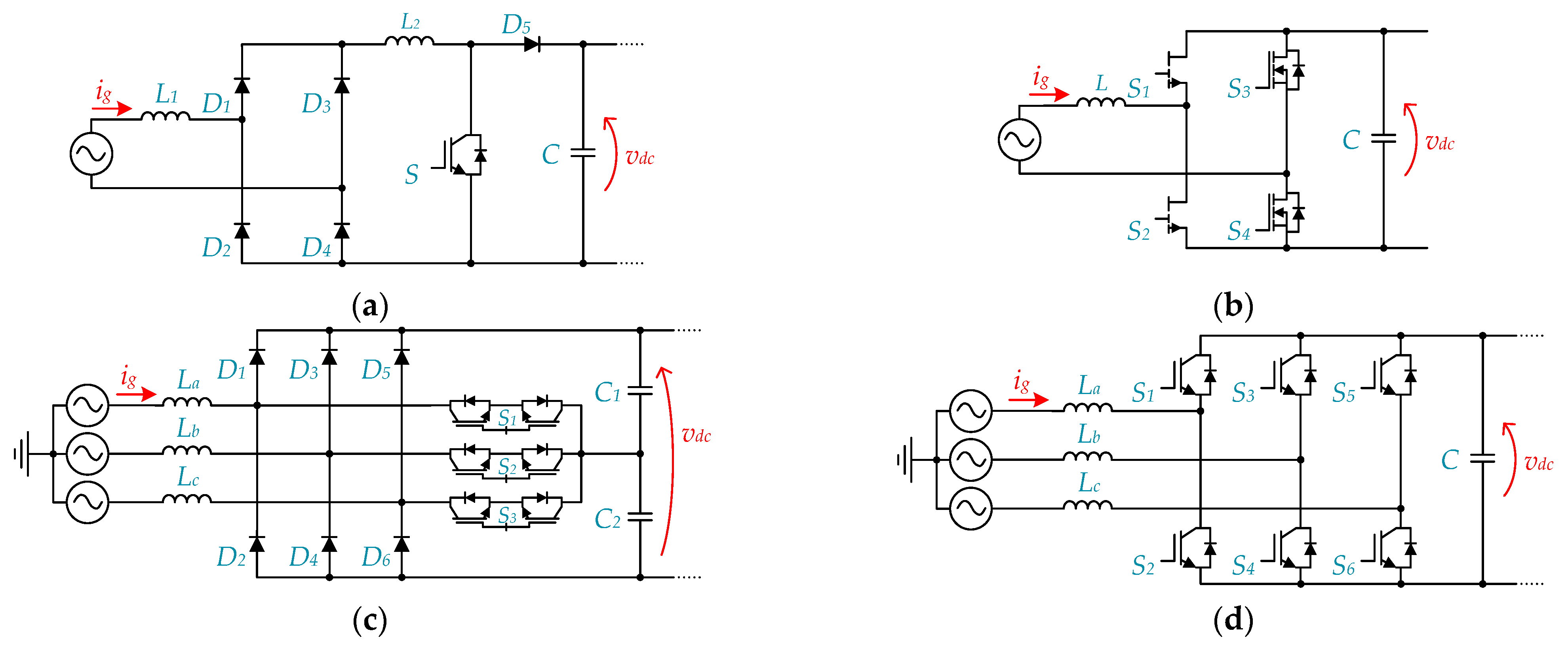
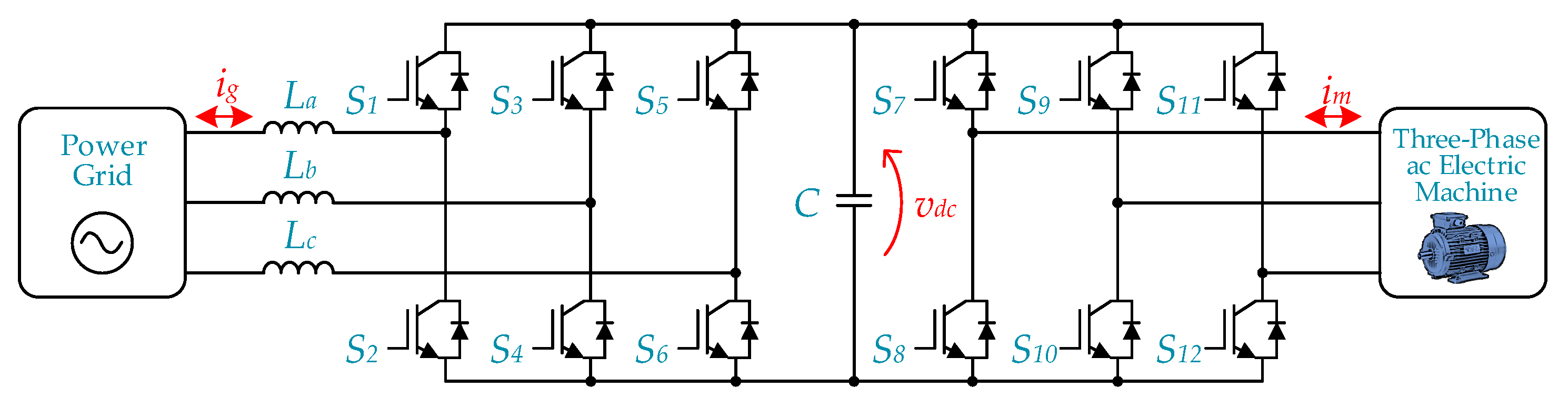
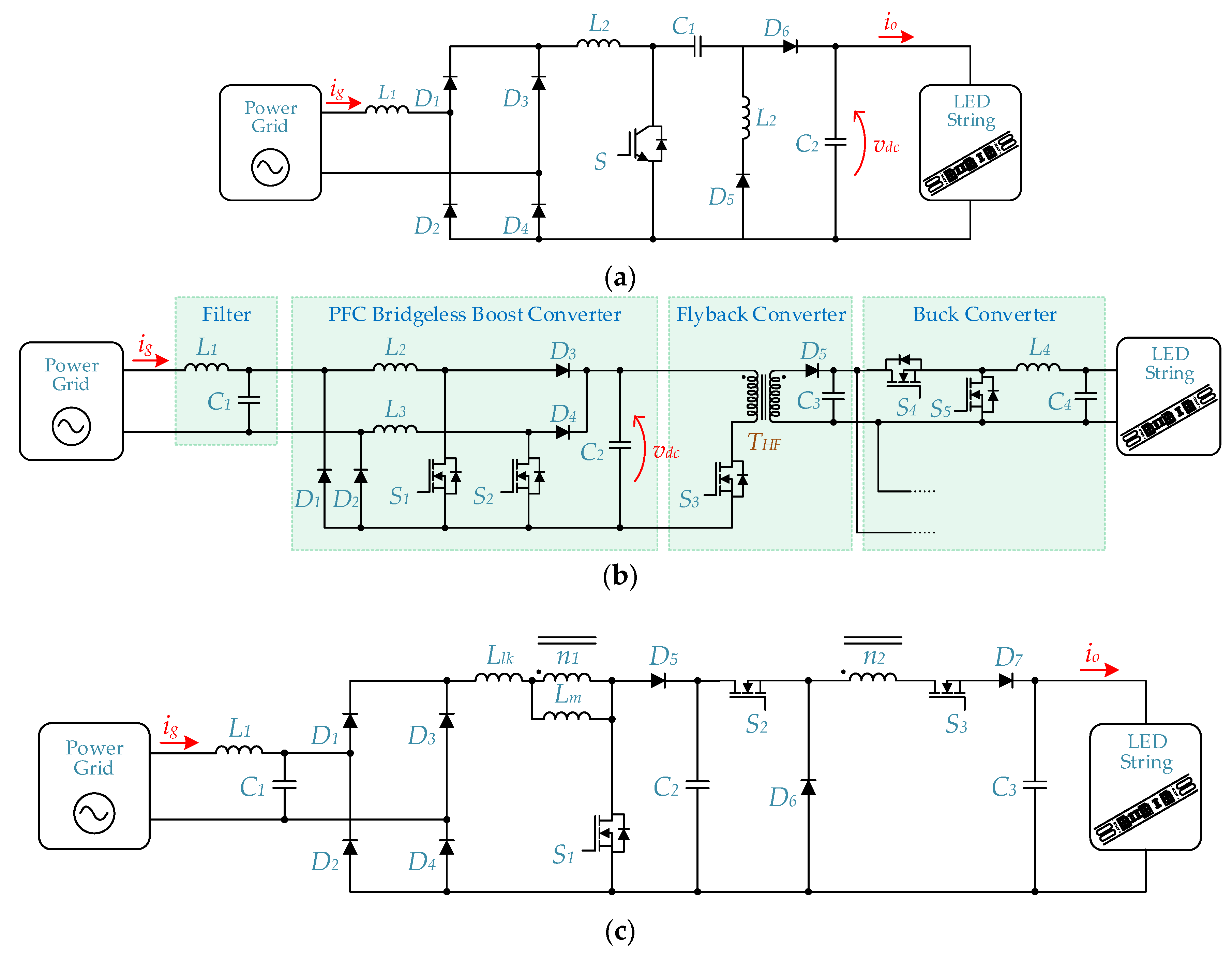
Figure 1. Different types of power quality problems.
Energies 14 08585 g001
Figure 2. Simplified electrical scheme of a hybrid PV-ESS system.
Energies 14 08585 g002
Figure 3. Power electronics converter for micro wind turbine: (a) Converter topology; (b) Developed prototype; (c) Laboratory setup to emulate the wind turbine, composed by a squirrel cage induction motor and a permanent magnet synchronous generator.
Energies 14 08585 g003
Figure 4. Experimental results of the micro wind turbine converter for two different wind speed scenarios: (a) Power grid currents for a rotation speed of 350 rpm; (b) Power grid currents for a rotation speed of 477 rpm; (c) Harmonic spectrum of the power grid currents for a rotation speed of 350 rpm; (d) Harmonic spectrum of the power grid currents for a rotation speed of 477 rpm; (e) Active power, apparent power, reactive power and power factor for a rotation speed of 350 rpm; (f) Active power, apparent power, reactive power and power factor for a rotation speed of 477 rpm.
Energies 14 08585 g004
Figure 5. Block diagram of the single-phase three-stage SST topology.
Energies 14 08585 g005
Figure 6. Single-phase building block of a three-phase SST topology for wind generation system applications.
Energies 14 08585 g006
Figure 7. SST applied to energy storage system (ESS).
Energies 14 08585 g007
Figure 8. SST for multi-port charging station infrastructure.
Energies 14 08585 g008
Figure 9. Main power electronics topologies applied as front-end power stage of on-board and off-board EV battery charging systems: (a) PFC; (b) Single-phase full-bridge; (c) Three-phase full-bridge; (d) Three-phase full-bridge interleaved.
Energies 14 08585 g009
Figure 10. Developed on-board EV battery charging system operating as shunt APF: (a) Example of a laboratory prototype; (b) Experimental results during G2V mode (vg: 100 V/div/ig: 10 A/div|5 ms/div); (c) Experimental results during G2V mode and compensating harmonic currents of the home (vg: 100 V/div/ih: 5 A/div/iev: 5 A/div/iea: 10 A/div|5 ms/div); (d) Experimental results only compensating harmonic currents of the home (vg: 100 V/div/ih: 5 A/div/iev: 5 A/div/iea: 10 A/div|5 ms/div).
Energies 14 08585 g010
Figure 11. Developed off-board EV battery charging system producing reactive power: (a) Example of a laboratory prototype; (b) Experimental results during EV battery charging (vga, vgb, vgc: 50 V/div/iga, igb, igc: 10 A/div|5 ms/div); (c) Experimental results during EV battery charging and producing reactive power (vga, vgb, vgc: 50 V/div/iga, igb, igc: 10 A/div|5 ms/div).
Energies 14 08585 g011
Figure 12. Operation principle of a shunt active power filter (ShAPF).
Energies 14 08585 g012
Figure 13. Basic structure of a ShAPF based on a: (a) Voltage source converter; (b) Current source converter.
Energies 14 08585 g013
Figure 14. Three-phase ShAPFs using ac–dc converters based on: (a) Three-wire three-leg; (b) Four-wire three-leg; (c) Four-wire four-leg.
Energies 14 08585 g014
Figure 15. Single-phase ShAPFs using ac–dc converters based on: (a) Half-bridge topology; (b) Full-bridge topology.
Energies 14 08585 g015
Figure 16. Three-phase ShAPF using multilevel ac–dc converters based on: (a) NPC; (b) Flying capacitor.
Energies 14 08585 g016
Figure 17. Basic structures of hybrid ShAPF using: (a) Series connection; (b) Parallel connection.
Energies 14 08585 g017
Figure 18. Simplified schematic of a three-phase SeAPF based on a voltage source inverter.
Energies 14 08585 g018
Figure 19. Simplified schematic of a three-phase back-to-back power converter to extend the compensation capabilities of the SeAPF.
Energies 14 08585 g019
Figure 20. Simplified schematic of a three-phase hybrid series active power filter (HySeAPF).
Energies 14 08585 g020
Figure 21. Experimental results with a three-phase transformerless series APF (TlSeAPF): (a) Power grid voltages (vSa, vSb, and vSc); (b) Load voltages (vLa, vLb, and vLc) and series APF voltages (vFa, vFb, and vFc); (c) Harmonic spectrum of the power grid voltages; (d) Harmonic spectrum of the load voltages.
Energies 14 08585 g021aEnergies 14 08585 g021b
Figure 22. Simplified schematic of a transformerless single-phase series APF (TlSeAPF).
Energies 14 08585 g022
Figure 23. Basic principle of both active filters compensating harmonic components.
Energies 14 08585 g023
Figure 24. Simplified diagram of the UPQC.
Energies 14 08585 g024
Figure 25. Experimental results of a three-phase four-wire UPQC in steady-state operation: (a) Power grid voltages, vSx, and load currents, iLx; (b) Load voltages, vLx, and power grid currents, iSx.
Energies 14 08585 g025
Figure 26. Basic structure of an offline UPS.
Energies 14 08585 g026
Figure 27. Basic structure of the line-interactive UPS with series inductor.
Energies 14 08585 g027
Figure 28. Basic structure of the delta conversion line-interactive UPS.
Energies 14 08585 g028
Figure 29. Basic structure of an online UPS.
Energies 14 08585 g029
Figure 30. Static VAr Compensator (SVC) in electrified railways. A, B, C refer to the three-phase voltages.
Energies 14 08585 g030
Figure 31. Static Synchronous Compensator (STATCOM) in electrified railways.
Energies 14 08585 g031
Figure 32. Static Frequency Converter (SFC) in electrified railways.
Energies 14 08585 g032
Figure 33. Rail Power Conditioner (RPC) in electrified railways. A, B, C refer to the three-phase voltages.
Energies 14 08585 g033
Figure 34. Co-phase Rail Power Conditioner (Co-RPC) in electrified railways. A, B, C refer to the three-phase voltages.
Energies 14 08585 g034
Figure 35. Typical PFC converter topologies: (a) Conventional boost PFC converter; (b) GaN totem-pole bridgeless PFC converter; (c) Vienna rectifier; (d) Active front-end.
Energies 14 08585 g035
Figure 36. Adjustable speed drive (ASD) with active front-end rectifier.
Energies 14 08585 g036
Figure 37. LED driver based on: (a) Modified SEPIC converter topology; (b) Flyback converter powered by a PFC bridgeless boost converter; (c) Electrolytic capacitor-less LED driver with coupled inductor based on a PFC boost converter cascaded with a buck converter.
Energies 14 08585 g037
Table 1. Voltage harmonics at the point of common coupling expressed as a percentage of the nominal voltage amplitude Vc (1 kV ≤ MV ≤ 36 kV, 36 kV ≤ HV ≤ 150 kV, 150 kV ≤ EHV ≤ 400 kV) [20].
Odd HarmonicsEven Harmonics
Not Multiples of 3Multiples of 3
Harmonic OrderRelated Voltage %Harmonic OrderRelated Voltage %Harmonic OrderRelated Voltage %
MVHVEHVMVHVEHVMVHVEHV
565335 *3 *1221.91.5
754291.51.314111
113.531.5150.50.50.360.50.50.5
1332.51.5210.50.50.280.50.50.4
172− **1>21 0.2100.50.50.4
191.5− **1 120.50.50.2
231.5− **0.7>120.50.50.2
251.5− **0.7
* According to the grid conception, this value of the 3rd order harmonic can be much lower. ** These harmonic orders should be in consideration according to the EN-50160 European norm. Note 1: Harmonic values higher than 25 orders are not indicated in the table due to their small amplitude. Note 2: THD in percentage, calculated in accordance with EN-50160, should not exceed 4% at the EHV.
Table 2. Current distortion limits for general distribution systems (120 V Through 69 kV) according to the IEEE 519 standard [31].
Isc/IL 3 ≤ h ≤ 1111 ≤ h ≤ 1717 ≤ h ≤ 2323 ≤ h ≤ 35
Isc/IL < 204%2%1.5%0.6%
20 < Isc/IL < 507%3.5%2.5%1%
50 < Isc/IL < 10010%4.5%4%1.5%
100 < Isc/IL < 100012%5.5%5%2%
Isc/IL > 100015%7%6%2.5%
ISC = maximum short circuit current at the point of common coupling. IL = maximum demand load current (fundamental frequency component) at the point of common coupling. Note 1: Even harmonics are limited to 25% of the odd harmonic limits above. Note 2: Current distortions that result in a dc offset, e.g., half-wave rectifiers, are not allowed.
Table 3. Comparison of the overall features of conventional PV systems and hybrid PV-ESS system relatively to power quality improvement.
Conventional PV-SystemHybrid PV-ESS System
Harmonic Currents Compensation+ + ++ + +
Reactive Power Compensation+ + ++ + +
Unbalanced Currents Compensation+ + ++ + +
Neutral Current Compensation+ + ++ + +
Voltage Sags Compensation+ ++ + +
Voltage Swells Compensation++
Undervoltage Compensation+ ++ + +
Table 4. Comparison of the main power electronics topologies applied as front-end power stage of on-board and off-board EV battery charging systems.
Unitary Power FactorPower Quality
Functionalities
BidirectionalSlow ChargingFast Charging
Power Factor CorrectionYesNoNoYesNo
Single-phase full-bridgeYesYesYesYesNo
Three-phase full-bridgeYesYesYesNoYes
Three-phase full-bridge interleavedYesYesYesNoYes
Table 5. Comparison between the different types of ShAPF.
Single-PhaseThree-Phase Three-WireThree-Phase Four-WireHybrid
Harmonic Currents CompensationYesYesYesYes
Reactive Power CompensationYesYesYesYes
Unbalanced Currents Compensation-YesYesYes (three-phase)
Neutral Current Compensation-NoYesYes (three-phase four-wire)
Resonance DampingNoNoNoCan be possible
Table 6. Comparisons between SeAPF devices for power quality improvement.
SeAPFBack-to-Back SeAPFHySeAPFTlSeAPF
Voltage Harmonics Compensation+ + ++ + ++ + ++ + + +
Voltage Sags Compensation+ ++ + ++ ++ +
Voltage Swells Compensation+ ++ + ++ ++ +
Voltage Unbalance Compensation+ ++ + ++ + ++
Overvoltage Compensation-+ + +--
Under voltage Compensation-+ + +--
Current Harmonics Compensation--+ +-
Estimated Costs+ ++ + + ++ + ++
Table 7. Comparisons between UPQC devices for power quality improvement.
UPQCUPQC without Series TransformersiUPQCTlUnPQC
Voltage Harmonics Compensation+ + ++ + +++ + ++ + +
Voltage Sags Compensation+ + ++ + + ++ + ++ +
Voltage Swells Compensation+ + ++ + + ++ + ++ +
Voltage Unbalance Compensation+ + ++ + + ++ + ++ +
Overvoltage Compensation+ + ++ + + ++ + +-
Under voltage Compensation+ + ++ + + ++ + +-
Current Harmonics Compensation+ + + ++ + ++ + + ++ + + +
Current Unbalance Compensation+ + + +-+ + + ++ + + +
Reactive Power Compensation+ + + ++ + ++ + + ++ + + +
Estimated Costs+ + ++ + + ++ + ++ + +
Table 8. Comparison between the different types of UPSs.
OfflineLine-Interactive (First Proposal)Line-Interactive (Delta Conversion)Online
Harmonic Currents CompensationYesYesYesYes
Reactive Power CompensationYesYesYesYes
Voltage RegulationNoYes (poor)YesYes
Frequency RegulationNoNoNoYes
Seamless TransitionNoNoYesYes
Table 9. Review papers in the literature for power quality improvement in railway systems using power electronics technologies.
[278]Opportunities and Challenges of Power Electronics Systems in Future Railway Electrification
[279]Electrical railway power supply systems: Current situation and future trends. International Journal of Electrical Power and Energy Systems
[280]Power Quality Phenomena in Electric Railway Power Supply Systems: An Exhaustive Framework and Classification
[281] Railway Traction Power Supply from the State of the Art to Future Trends
[282] Power Quality Phenomena in Electrified Railways: Conventional and New Trends in Power Quality Improvement toward Public Power Systems
[283] Application of Power Electronics in Improving Power Quality and Supply Efficiency of AC Traction Networks
[284] Future of Electric Railways: Advanced Electrification Systems with Static Converters for AC Railways
[285] Use of converters for feeding of AC railways for all frequencies
[286] Topologies and Operation Modes of Rail Power Conditioners in AC Traction Grids: Review and Comprehensive Comparison
[287] Analysis and Comparison of Modular Railway Power Conditioner for High-Speed Railway Traction System
Table 10. Comparisons between FACTS devices for power quality improvement in electrified railway applications.
SVCSTATCOMSFCRPC
Harmonics Compensation++ + ++ + ++ + +
NSC Compensation+ ++ + ++ + ++ + +
Power Factor Correction+ ++ + ++ + ++ + +
Reactive power compensationYesYesNo needYes
Active power supply 1NoNoYes (fully)Yes (partially)
Frequency ConversionNoNoYesNo
Passive Filter size+ + ++ +++ +
Power Ratings 2+ ++ + ++ + + ++ + +
Neutral Section 3YesYesNoYes 4
Overloading CapabilityYesYesNoYes
Dynamic ResponsePoorGoodGoodGood
Estimated Costs++ ++ + + ++ + +
1 Active power supplied directly from the converter to the traction loads. 2 Power ratings of the converter per unit load. 3 Only neutral sections in the same traction substation (in front of the traction substation), but not between two traction substations. 4 The neutral section can be omitted by using Co-RPC.
Publisher’s Note: MDPI stays neutral with regard to jurisdictional claims in published maps and institutional affiliations.

