Article

Full-Stress Anchoring Technology and Application of Bolts in the Coal Roadway

1
Key Laboratory of Deep Coal Resource Mining of the Ministry of Education, School of Mines, China University of Mining and Technology, Xuzhou 221116, China
2
Shaanxi Shanmei Caojiatan Mining Co., Ltd., Yulin 719000, China
*
Author to whom correspondence should be addressed.
Energies 2021, 14(22), 7475; https://doi.org/10.3390/en14227475
Submission received: 9 October 2021 / Revised: 27 October 2021 / Accepted: 3 November 2021 / Published: 9 November 2021
(This article belongs to the Special Issue Rock Burst Disasters in Coal Mines)

Abstract

:
The traditional anchoring method of bolts has insufficient control over the surrounding rock of the coal roadway. Based on this background, full-stress anchoring technology of bolts was proposed. Firstly, a mechanical relationship model of a bolt-drawing, anchoring interface was established to obtain the equations of the axial force and obtain shear stress distribution as well as the decreasing-load transfer law of the anchoring section of bolts. Through studying the prestress-loading experimental device of bolts, we found that increasing the initial preload could increase the axial force under the same conditions and the retarded anchoring section could control the axial-force loss of bolts in the middle of the anchoring section. Under the full-stress anchoring mode, the effect of applying a pre-tightening force was better than that of applying a pre-tightening force under traditional anchoring methods. Moreover, FLAC3D (Fast Lagrangian Analysis of Continua 3D; ITASCA (Ita sca International Inc), Minnesota, USA) numerical simulation calculation was performed. Under the full-stress anchoring mode of bolts, the increased anchoring length reduced the damage of the anchoring section, with a wider control range of the rock formation and higher strength of the compressive-stress anchoring zone. Based on the above research, four methods for applying the full-stress anchoring technology of bolts in engineering were proposed. The full-stress anchoring technology of bolts in the coal roadway has been applied in the support project of the return-air roadway at working face 3204 of the Taitou Coking Coal Mine of the Xiangning Coking Coal Group, Shanxi. The maximum moving distance of the roof and floor of the roadway was reduced from 200 to 42 mm, and the maximum moving distance on both coal sides was reduced from 330 to 86 mm. The full-stress anchoring technology of bolts was able to control the surrounding rock in the coal roadway.

Graphical Abstract

1. Introduction

As the mining depth increases, the roadway and surrounding rock masses not only face the effects of high ground stress but also experience strong mining stress during roadway driving and mining [1,2,3]. Under the mutual superposition of high ground stress and strong mining stress, the roadway and surrounding rock masses generally have problems such as the strength deterioration of surrounding rock, deterioration of the stress environment, and structural instability and large deformation of surrounding rocks [4,5,6]. In severe cases, roof fall and slabs may occur [7,8].
As an active support method of the coal roadway, bolt support is widely used in the coal roadway because of its high support strength and low cost [9,10]. In recent years, the carrying capacity of single bolts has been strengthened [11,12]. However, the theoretical analysis and design of anchoring technology have developed slowly, and the anchoring and supporting technology lacks a theoretical basis due to the complex force of the anchor rod in the supporting process [13,14]. The research on the distribution of prestress in the process of controlling the surrounding rock by the bolt body is the focus of the bolt supporting technology [15,16].
At present, bolt support has become one of the main forms of coal mine roadway support in China [17,18,19,20,21]. From solid coal roadways to the gob-side entries retaining and driving, and from shallow roadways to deep high-stress roadways, it exists in various roadway support designs in coal mines [22,23]. From the perspective of the actual construction process of the coal mine, the process of coal roadway bolt supports mostly includes drilling, anchoring agent insertion, mixing, gel, and bolt tensioning [24,25]. This anchoring method has several disadvantages, e.g., affecting the transmission of the anchoring force, reducing the control effect on the surrounding rock, invalid anchoring sections of bolts, wastage of anchoring materials, and threats to safe production [26,27,28]. Therefore, mastering reasonable coal roadway bolting technology and designing reasonable support schemes are of great significance to the safe production of coal mines [29,30,31,32].
Kang [33] believed that the essential function of the bolt is to control the expansion deformation and destruction of the surrounding rock in the anchoring zone, such as separation, sliding, crack opening, and new cracks, forming a prestressed load-bearing structure with greater rigidity in the anchoring zone. Zhang [34,35] et al. developed high-strength pre-tension bolts based on the performance of bolt components and proposed the high-strength prestressed bolt support technology for coal roadways. The stress state of the roof is improved to eliminate tensile failure, and the weakened area of the surrounding rock is controlled to eliminate loose deformation. Wu [36] studied the influence of different anchoring methods on roadway supports and believed that the full-length prestressed anchoring system increases the sensitivity to strata separation and dislocation. You [37,38] obtained an elastic solution of the shear force distribution of the full-length bonded bolt along its body through theoretical calculations and obtained the normal stress and shear stress distribution law along the axial direction of bolts as well as the evolution process with the increased load. Zheng [39,40,41] used MATLAB software (MathWorks Inc., Natick, MA, USA) to study the influence of the anchoring method, surrounding rock properties, bolt diameter, and pre-tightening force on the distribution of prestress in the bolt body and surrounding rock. Furthermore, the bolt-supporting parameters were optimized. Lian [42] studied the load transfer law of the anchoring section of bolts. The analytical solution of the critical anchoring length of bolts was obtained through theoretical calculation, and a method to increase the load of the anchorage section of the bolt was proposed from industrial tests. Krzysztof Skrzypkowski [43,44,45] applied the stress monitoring system to monitor the stress distribution of the rock strata and believed that in deep mining, the area where the roof of the roadway is easily deformed should have an increased safety factor when using segmented bolt support to make it more yieldable, especially for the layered roof. The segmented embedded bracket of resin bolts is yieldable, enabling it to complete additional work. Yao [46] studied the variation of shear stress and axial force of the anchoring section along the anchoring bottom with different anchoring lengths of threaded steel bolts, believing that increasing the anchoring length can improve the bearing capacity of bolts. Xiao [47] adopted a multi-functional bolt-drawing test system, revealing the mechanical properties of bolt drawing in the coal mine under different anchoring lengths. The greater the anchoring length, the greater the pull-out force of bolts; however, a critical anchoring length exits. Huang [48] used the load transfer method to analyze the influence of the anchorage length on the force characteristics of bolts. As the anchorage length increases, the unevenness of the interfacial shear stress distribution becomes increasingly obvious, and the overall bearing capacity also increases. Yang [49] discussed the force evolution mechanism of bolts and proposed that the roadways with different deformation characteristics should adopt different anchoring lengths. Therefore, the bolts should be kept in the deformation stage of the anchoring force as much as possible when the surrounding rock deforms. Zhu [50] used FLAC3D software to simulate the influence of the number of bolts on the anchoring of the layered rock mass. As the number of bolts increases, the peak strength and elastic modulus of the anchored rock formations gradually increase. Wang [51] believed that the anchoring agent can relieve the increased stress of the rock mass in the lengthening anchoring of bolts and is the most sensitive to the joint shear deformation. The resistance increases over time to inhibit the shear slip of the rock mass. Xiang [52] used 4-m flexible bolts to support the roof of the coal roadway, optimize the stress environment of the surrounding rock of the roof, and restrain the damage of the anchoring structure. Zhao [53] studied the relationship between rib spacing and the anchoring effect of bolts. Under different surrounding rock conditions, increasing the rib spacing can improve the anchoring performance.
These research results provide a technical reference for using bolts to support the surrounding rock of coal roadways, but there is still room for improvement in the transmission mechanism of the axial force of bolts and the prestress distribution in the anchoring zone.
The axial force and shear stress transfer formulas of the anchoring section of the bolt were calculated by constructing a mechanical model in the work. Besides establishing the prestress-loading experiment device of bolts, the pre-tightening force, traditional pre-stressed anchoring, and full-pre-stressed anchoring were used as research variables. The full-stressed anchoring method was more effective, and the pre-tightening force affected the prestress of the anchoring section of bolts. The numerical simulation method was used to determine the influence law of the anchorage length on the full-stress anchoring effect of bolts. Finally, the full-stress anchoring technology of bolts and its engineering application method was obtained. The full-stress anchoring technology of bolts has been applied in the support project of the return-air roadway at working face 3204 of the Taitou Coking Coal Mine of the Shanxi Xiangning Coking Coal Group. The results of roadway deformation monitoring showed that this technology could control the deformation of the surrounding rock of coal roadways, with a good supporting effect and feasibility.

2. Load Transfer Mechanism of the Anchoring Section of Bolts

2.1. Full-Stress Anchoring

Full-stress anchoring of bolts is the term used for full-length pre-stressed anchoring of bolts, rather than the term for full-length anchoring of bolts. Full-stress anchoring can use end anchors, lengthened anchors, and full-length anchors. The key to the full-prestressed anchoring of bolts is that the full length of the bolt has an effective pre-stress distribution. In the work, the full-stress anchoring technology of bolts was applied as the bolt-lengthening anchoring method.

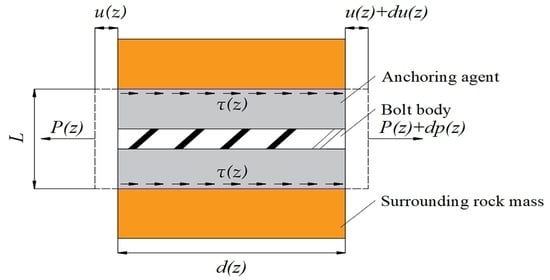
2.2. Mechanical Relationship Model of the Bolt-Drawing Anchoring Interface

When the load distribution law of the bolt-drawing state is studied, the most-used three-stage mechanical relationship model is combined to describe the deformation law of different stages. Benmokrane’s [54] theory divides the entire working process of the anchoring interface in the drawing process into three deformation stages (see Figure 1).
In the mechanical relationship model, the displacement of the anchoring body is the horizontal axis, denoted by u , and the shear stress is the vertical axis, denoted by τ . A represents the elastic deformation stage, B is the softening loss stage, and C is the residual strength stage. M is the softening yield point, while N is the failure point of the anchoring interface. In the formula, τ 1 is the peak bond strength, u 1 is the final shear displacement value at stage A, u is the shear displacement, τ 2 is the residual bond strength of the anchoring interface, u 2 is the final shear displacement value at stage B, and u is the shear displacement.

2.3. Load Transfer Law of the Anchoring Section

According to the mechanical relationship model of the bolt-drawing anchoring interface in Figure 1, the characteristics of the force change at each stage are as follows.
In elastic deformation stage A, the shear stress is proportional to the shear displacement, with an intact anchoring system and the interface in good condition. Then the shear stress is
τ = τ 1 u 1 u
In softening loss stage B, the shear stress of the anchoring section decreases with the increased shear displacement. The elastic zone and the plastic zone coexist in the anchoring system, and shear stress τ is
τ = τ 2 τ 1 u 2 u 1 u + τ 1 u 2 τ 2 u 1 u 2 u 1
In residual strength stage C, the friction force between the bolt and the anchoring body maintains the stability of the anchoring interface, and shear stress τ is
τ = τ 2
Studying the anchoring system in the elastic deformation stage, the cross-sectional area of the anchoring section remains unchanged, and the influence on Poisson’s ratio is negligible. The load transfer law of the anchoring section of the bolt conforms to Hooke’s law. In the anchoring system at the elastic deformation stage, a micro-element of the anchoring section is selected for the elastic deformation section (see Figure 2).
In the full-length anchoring system of bolts, the length of the anchoring section L b shall meet 1 / 3 L a L b 0.9 L a , where L a is the length of the drilled hole and L b is the length of the anchoring section of bolts.
Figure 3 shows the force of the micro-element in the anchoring section.
According to the geometric equations and physical equations of rock mechanics, the relationship between axial force and deformation is obtained.
d u ( z ) d z = 4 P ( z ) π L 2 E a
d P ( z ) d z = π L τ ( z )
where P ( z ) is the axial load of the anchoring body at coordinate z, u ( z ) is the axial displacement of the anchoring body at coordinate z, τ ( z ) is the shear stress of the anchoring body at coordinate z, L is the borehole diameter, and E a is the elastic modulus of the anchoring section.
Considering the bolt and the anchoring section of the anchoring agent as a whole, the elastic modulus E a of the anchoring section is
E a = E b ( L 2 l 2 ) + E c l 2 L 2
where E b is the elastic modulus of the anchoring agent, E c is the tensile elastic modulus of the bolt, and l is the diameter of the bolt.
Equations (4) and (5) are used to derive
d 2 u ( z ) d z 2 = 4 τ ( z ) L E a
When the interface of the anchoring body and the surrounding rock is in the elastic deformation stage, Equation (1) shows that there is a proportional coefficient between the shear stress and the shear displacement, which is expressed by constant K . Then the micro-element shear-stress transfer function of the anchoring section can be obtained.
τ ( u ) = K u
Equation (8) is substituted into Equation (7) to derive
d 2 u ( z ) d z 2 = 4 K u L E a
After introducing the constant θ , the value is
θ = 4 K L E a
Equation (10) is substituted into Equation (9). After simplification, we obtain
u θ 2 u = 0
Equation (11) is solved to derive
u ( z ) = C 1 e θ z + C 2 e θ z
The axial force at the beginning of the anchoring section is
P z = 0 = P
The tail axial force of the anchoring section is
P z = l = 0
Equations (13) and (14) are substituted into Equations (9) and (10) to derive
C 1 = 4 P e 2 θ l π L 2 θ E a ( 1 e 2 θ l )
C 2 = 4 P π L 2 θ E a ( 1 e 2 θ l )
From Equations (4), (12), (15), and (16), the axial-force distribution formula of the anchoring body is
P ( z ) = e 2 θ z e 2 θ l e θ z ( 1 e 2 θ l ) P
Substituting Equation (17) into Equation (5), the shear stress distribution formula between the anchoring body and the surrounding rock interface can be obtained as
τ ( z ) = e 2 θ z + e 2 θ l π L e θ z ( e 2 θ l 1 ) θ P
Equation (17) is mathematically derived within the anchoring length, and the derivative is less than 0, showing that the axial force of the anchoring body is transmitted in a decreasing manner in the anchoring section. Derivation of Equation (18) within the anchoring length shows that the shear stress of the anchoring interface decreases with a decreasing function.
The maximum shear stress τ max of the anchoring section is expressed as
τ max = τ 1 = 1 + e 2 θ l π L ( e 2 θ l 1 ) θ P
The ultimate pullout resistance P max is
P max = π L τ 1 ( e 2 θ l 1 ) θ ( 1 + e 2 θ l )

3. Full-Stress Anchoring Experiment of Bolts

3.1. Experimental Device for the Prestressed Loading of the Bolt

According to Ref. [55], when the bolts are pre-stressed to anchor the surrounding rock by the traditional method, the prestressed diffusion and transmission range is smaller, and the supporting effect on the surrounding rock is not sufficient with the long anchoring section of bolts. Therefore, the end-anchoring method is often used in the actual engineering of supports in the coal roadway. Although the method has a good prestressed diffusion and transmission range, the control ability on the surrounding rock is insufficient, which means anchoring failure occurs easily. A comparative test of traditional anchoring and full-stress anchoring of bolts was carried out to study the full-stress anchoring effect of bolts.
The prestressed loading test device of the bolt was mainly composed of a loading system and an anchoring system. The loading system simulated the process of applying prestress to the bolt after it was equipped with a bearing plate, washers, and nuts, and the tool was a digital torque wrench. The anchoring system was composed of six chucks of the bolt, which could clamp and fix the bolt and simulate the anchoring effect of the anchoring agent on the bolt. Other parts of the experimental device included a strain data collector, a comprehensive-parameter tester, and a load tester. Figure 4 and Figure 5 show the effect diagram and physical diagram of the loading experimental device, respectively.

3.1.1. Loading System

CML300 Torque Wrench

The CML300 torque wrench is composed of a torque sensor, an MCU control chip, a data storage chip, a data display screen, and other materials. It has the following advantages: Applying an anchor pre-tightening force, recording the torque size and construction time, facilitating project inspection, improving construction quality, and a construction error less than 4% (see Figure 6).
The CML300 torque wrench is used to apply pre-tightening force to bolts, with the maximum pre-tightening force of 50 kN. When the bolt is placed in the chuck, the torque wrench is used to tighten the nut to apply pre-tightening force to the bolt; when the display value reaches the required pre-tightening force, screwing stops.

Manual Hydraulic Oil Pump

The manual hydraulic oil pump is mainly composed of a pump body, a handle, an oil storage tank, and a pressure gauge, with a stable output oil pressure of 60 MP (see Figure 7).
The handle is manually pressed to drive the plunger to reciprocate. The hydraulic oil is pressed to the high- and low-pressure one-way valve into the oil cylinder to realize filling, boosting, working, and the drawing of bolts. During the drawing process, one must observe the pressure gauge and stop pressing the handle when the requirements are met. After drawing the bolts, the oil pump pressure relief valve is opened to complete the pressure relief.

3.1.2. Anchoring System

The anchoring system is mainly composed of six bolt chucks. The clamping range of the chucks is 8–250 mm, with a theoretical clamping force of 90 kN, a theoretical clamping pressure of 60 MPa, and a net weight of 30 kg (see Figure 8).
The sequence of holding the anchor rod by six chucks can be used to simulate the process of anchoring the bolts by quick- and slow-setting anchoring agents in the full-stress anchoring method.

3.1.3. KJ327-F Strain Data Collector

The KJ327-F strain data collector can monitor the drawing deformation of bolts. There are 16 channels in total, and each channel has wiring ports a, b, c, and d, (see Figure 9). The experiment used channels 1–12, and the bridge type of the connection port was a quarter bridge. Temperature compensation was performed through the common compensation chip interface before monitoring began. The collector was connected to the PC end to monitor the whole bolt-drawing process, and a time–strain curve, a collecting grid–strain curve, and a channel–strain curve were formed to ensure that the anchoring body was in the elastic deformation stage during the experiment. The bolt diameter, length, tensile strength, yield strength, elongation, yield load, tensile load, and other parameters of the bolt were input into the PC software, and the axial force of the bolt was calculated at each strain gauge measurement point.

3.1.4. Comprehensive Parameter Tester of CD-4 Bolt

The two interfaces of the comprehensive parameter tester of the CD-4 bolt are separately connected to the hydraulic oil pump and the pre-stress loading experimental device of bolts, which can display the bolt-drawing displacement and oil pump pressure on the dial. Combined with the pressure gauge reading of the hydraulic oil pump, it is ensured that the output drawing force of the hydraulic oil pump meets the drawing force requirements of the experimental design (see Figure 10).

3.1.5. Load Tester of the GDP60 Bolt

The load tester of the GDP60 bolt was used to determine the load value of the bolts (see Figure 11). The sensing end was connected between the nut and the hydraulic oil pump, and the sensing end transmitted the monitoring data to the display screen. The reading on the display was the actual pre-tightening force applied to the starting end of the bolt. In the process of applying the pre-tightening force, the display value of the tester of the GDP60 bolt should be observed to ensure that the applied pre-tightening force meets the experimental design plan.

3.1.6. Experimental Bolt

This experiment used a screw steel bolt with a specification of Φ 20 × 2400 mm, with a yield strength of 345 MPa, a tensile strength of 510 MPa, a yield load of 108 kN, a tensile load of 156 kN, and an elongation rate of 25% (see Figure 12).

3.2. Prestressed Loading Experiment Scheme

The pre-stress loading experiment of bolts is conducted to study the initial pre-tightening force, the use of quick- and slow-setting anchoring sections, and the influences of the full-stress anchoring and the traditional pre-stressing anchoring on axial force transmission and pre-stress diffusion. The experimental design is as follows:
(1)
8 mm rebar bolts with the same body parameter of Φ 20 × 2400 mm were taken. We randomly divided two groups into four groups, and the grouping numbers were I, II, III, and IV in sequence. In the four groups, the bolts were numbered 1 and 1+, 2 and 2+, 3 and 3+, and 4 and 4+.
(2)
The bolts of groups I-IV were separately applied with pre-tightening forces of 10, 20, 30, and 40 kN, and the bolts numbered 1, 2, 3, and 4 were tightened with six chucks and then tensioned. We then simulated the method of applying the pre-tightening force of the traditional bolts, and the bolts numbered 1+, 2+, 3+, and 4+ were first tightened with three chucks at the end of the bolt and tensioned. Then, we tightened the remaining three chucks to simulate the pre-tightening force application method of the full-stress anchoring bolt.
(3)
Six sets of strain gauges were posted at equal intervals on each bolt. The corresponding measuring point numbers were 1#, 2#, 3#, 4#, 5#, and 6#, with two strain gauges in each group (see Figure 13). The strain data collector collected the data and sent them back to the computer to calculate the axial force of bolts.

3.3. Analysis of Axial Force Monitoring Data of Bolts

Table 1 shows the experimentally measured axial force data of bolts.
According to the data in Table 1, the change curve of the axial force of the bolts in groups I-IV can be obtained (see Figure 14).
By analyzing the axial force change curves of the four groups of anchor rods in Figure 14, the transmission law of the axial force of bolts under different pre-tightening forces and different anchoring methods is as follows:
(1)
For the two anchoring methods of traditional prestressed anchoring and full-stress anchoring, under the same anchoring method, the axial force values corresponding to the same bolt from the anchoring tail end measuring point 1# to the beginning measuring point 6# were gradually reduced, which conformed to the load transfer law of the anchoring section of bolts obtained in the theoretical analysis.
(2)
The axial force values of bolts in groups I~IV at the same position under the same prestressed anchoring method increased with the increased initial preload. It showed that appropriately increasing the pre-tightening force could increase the axial force of bolts under the same conditions and enhance the pre-stress transmission of the anchoring section. However, with an increased initial preload, the axial force loss rate of bolts with a high preload was higher under the same transmission length.
(3)
Comparing the axial force values of the two different anchoring methods in the same position of the bolts in groups I-IV, the axial force values of 1+, 2+, 3+, and 4+ were greater than those of 1, 2, 3, and 4. The difference between the axial forces of the former and the latter showed a “small–large–small” change rule, indicating that the anchoring effect of the anchoring section applied in the subsequent sequence was to control the axial force loss of the bolts in the middle of the anchoring section. That is to say, the significance in actual engineering was that the retarded anchorage section of the anchorage section of bolts lagged behind the quick-setting anchorage section of the bolt end. It was able to control the axial-force loss in the middle of the anchorage section, thereby improving the prestress diffusion of bolts. Meanwhile, the pre-stress transmission of the full-stress pre-tightening force application method of bolts was better than that of the traditional method.

4. FLAC3D Numerical Simulation Analysis of Anchoring Length on the Full-Stress Anchoring Effect of Bolts

4.1. FLAC3D Numerical Simulation Model Material Parameters

The FLAC3D numerical simulation model was established to study the effect of different anchoring lengths on the surrounding rock of bolts under the traditional prestressed anchoring method and the full-stress anchoring method. The experimental material parameters required to establish the model mainly included the mechanical parameters of the surrounding rock, bolt parameters, and anchoring-agent parameters. A rock core was obtained on the mudstone roof of the return-wind roadway at working face 3204 of the Taitou Coking Coal Mine. The tensile and shear resistances of the rock core were measured by the MTS electro-hydraulic servo testing machine to obtain mechanical parameters. The parameters of the bolts and the anchoring agent adopted the performance parameters provided in the product manual, with the anchoring agents of CK2350 and K2370. Table 2 shows the mechanical parameters of materials in the numerical simulation experiment.
A cube model with a model size of 5 × 5 × 5 m was established. The rebar bolt had a specification of Φ 20 × 2400 mm, and the bolt body was perpendicular to planes X and Y.

4.2. Simulation Schemes of Different Anchorage Lengths

The following preconditions needed to be met to study the influence of different anchoring lengths on the prestress distribution of the anchoring section of bolts:
(1)
Regardless of the initial ground stress, only the pre-tightening force was applied to bolts.
(2)
The boundary displacement of the model was restricted to 0, and the anchoring body was always in the elastic deformation stage when the preload was applied.
After satisfying the prerequisites, the experimental plan was designed as follows:
(1)
The initial pre-tightening force of the control bolts was 60 kN, and the mechanical parameters of the anchored surrounding rock using mudstone remained unchanged.
(2)
Two anchoring methods were used, namely the full-stress anchoring method and the traditional pre-stressed anchoring method of bolts. The latter was the control test group of the former.
(3)
The length of the anchoring section was controlled to meet the requirements of lengthening anchoring, and the designed anchoring lengths were 0.9, 1.3, 1.7, and 2.1 m, respectively.
(4)
The stress distribution of the surrounding rock in the YY direction was recorded under different anchorage lengths. The established numerical simulation model should reach the operational balance and then stop after starting the operational command to meet the precise experimental requirements.

4.3. Analysis of the Full-Stress Anchoring Effect of Bolts under Different Anchoring Lengths

The stress distribution of the surrounding rock in direction YY was used to analyze the pre-stress control effect of different anchorage lengths on the surrounding rock under the full-stress anchoring mode, and the distribution at the anchoring lengths of 0.9, 1.3, 1.7, and 2.1 m was obtained (see Figure 15).
According to the comparison test of traditional pre-stressed anchoring and full-stressed anchoring of bolts with four groups at the anchoring lengths of 0.9, 1.3, 1.7, and 2.1 m in Figure 15, the following conclusions can be drawn:
(1)
Comparing Figure 15a,c,e,g obtained under the traditional prestressed anchoring method of bolts, the stress value of the tensile stress concentration area at the end of the anchoring section gradually decreases as the anchoring length increases. Therefore, increasing the anchoring length is beneficial to the quality of bolt construction and reducing the damage in the anchored section.
(2)
Comparing Figure 15b,d,f,h, the pre-stress diffusion range gradually decreases as the anchoring length increases, and the control range of the surrounding rock is gradually reduced. However, after the anchorage length increases, the stress value of the compressive stress zone is higher than that of the shorter anchoring length, with stronger control over the surrounding rock. Therefore, the anchorage length should be increased to control the rock stratum. At this time, the key lies in the time difference between quick- and slow-setting anchoring sections in establishing the full-stress anchoring method of bolts. Before the retarded section is solidified, a pre-tightening force is applied to bolts in time to give full play to the advantages of the short anchorage length and the larger pre-stress spreading range, thus expanding the control range of the surrounding rock. When the retarded section is solidified, the long anchor section formed by combining the quick-set anchor section and the retarded anchor section can keep the stress value of the compressive stress zone high and enhance the control strength of the surrounding rock.
(3)
Comparing (a) and (b), (c) and (d), (e) and (f), (g) and (h), under the same pre-tightening force, the same anchoring length, the same anchoring surrounding rock lithology, and the same bolt parameters, the full-stress anchoring method of bolts has a wider diffusion range of pre-stress and a larger effective continuous compressive stress area than the traditional pre-stressed anchoring method of bolts. Therefore, it has been proved once again that under the same conditions, the full-stress anchoring method of bolts has better control over the surrounding rock than the traditional pre-stressed anchoring method.

5. Engineering Application of the Full-Stress Anchoring Technology of Bolts

5.1. Engineering Method to Realize the Full-Stress Anchoring Technology of Bolts

Based on the above conclusions drawn from the above research on the load transfer mechanism of the anchoring section of bolts, the full-stress anchoring laboratory simulation experiment of bolts, and the FLAC3D numerical simulation experiment, the method of realizing the full-stress anchoring technology of bolts in engineering application is as follows:
(1)
The initial pre-tightening force of the anchor rod was increased and an appropriate length of bolt was selected. The key to full-prestressed anchoring of bolts is that the full length of the bolt has an effective pre-stress distribution. Increasing the initial pre-tightening force can increase the pre-stress value along the entire length of the bolt. The choice of length should be combined with the mechanical characteristics and development of the surrounding rock. For rock strata exhibiting low mechanical strength, severe deformation and damage, and well-developed joints and fissures, the length of the bolts must be increased, so the ends of the bolts can be anchored at a position where the rock strata has good integrity to ensure the restricted expansion of the weak rock stratum area.
(2)
Synergistic use of quick- and slow-setting anchoring agents with different coagulation rates. The bolt driller was used to construct the bolt hole, and the generated cuttings were removed from the drill hole. Firstly, the quick-setting anchoring agent was placed in the deep part of the borehole. After the slow-setting anchoring agent was placed behind the quick-setting anchoring agent, the bolt was inserted for stirring. After the quick-setting anchoring agent was coagulated, the pre-tightening force was applied to the entire bolt when the retarding anchoring agent had not coagulated. Thereby, the prestressing range increased, and a larger range of effective compressive stress thickness formed. The anchoring agent filled the gap between the bolt body and the surrounding rock. Bonding the bolt body and the borehole wall can improve the sensitivity of the bolt body to the deformation and separation of the surrounding rock, thereby restraining the separation and sliding of the surrounding rock in a timely manner.
(3)
The total anchorage length of the anchorage section of bolts was increased and the total anchorage length was maintained to meet the requirements of extended anchorage length. In the full-stress anchoring method of bolts, the total anchoring length was the sum of the anchorage length of the quick- and slow-setting sections. After increasing the total anchorage length, the difference in the setting time of the anchoring agent between the quick-setting section and the slow-setting section was used to apply the pre-tightening force to bolts. This enabled us to expand the prestress distribution range and maintain a high prestress value, which enhanced the control range and control strength of the bolts on the surrounding rock.
(4)
The row spacing between bolt supports in the full-stress anchoring mode was increased. Under the full-stress anchoring method, the shape of the pre-stress range formed by anchoring the surrounding rock with a single bolt was similar to shape “∩”, which was better than that of the traditional pre-stressed anchoring method. The row spacing between bolt supports could be increased to form a continuous, thick, pre-stressed squeeze zone between the bolts, thus realizing the full-stress anchoring technology of bolts to control the surrounding rock of large-area and large-span roadways.

5.2. Mining Conditions

Coal seam 2 of the Taitou coking coal mine of the Shanxi Xiangning Coking Coal Group has an average thickness of 3.5 m, an average coal seam inclination of 10°, low gas content, and a buried depth of about 700 m, which makes it a high-stress, deep-buried coal seam. The immediate roof is mudstone with a thickness of about 2.8 m, the main roof is fine sandstone with a thickness of about 5.5 m, and the floor is sandy mudstone with a thickness of about 5 m. Figure 16 shows the comprehensive histogram of rock strata.
Working face 3204 is arranged in coal seam 2, located on the south side of the return-air downhill in mine district 3, adjacent to working face 3206 and the gob area of working face 3202. The north side of the return-air tunnel of working face 3204 is the roadway of mining district 3, the south side is the boundary of mining district 3, the west side is a solid coal seam, and the east side is a 30 m section protection coal pillar and the gob of working face 3202. Figure 17 shows the layout of the roadway.
The return-air roadway of working face 3204 is affected by high ground stress and mining. The surrounding rock of the roadway is extensively deformed. The displacement of the roof and floor can reach 200 mm while that of the coal side can reach 330 mm.

5.3. Full-Stress Anchoring Support Plan of Bolts

In order to solve the serious problem of the surrounding rock deformation of the return-air roadway in working face 3204, the full-stress anchoring technology of bolts in the coal roadway is now used to optimize the roadway support plan as follows:
(1)
One roll of CK2350 and one roll of K2370 resin anchoring agent were used to replace the original two rolls of K2370 during the process of anchoring the roof and bolts in the roadway. In the construction of the bolts, CK2350 and K2370 were inserted into the borehole in turn. The difference in the setting time of the two anchoring agents was used to apply pre-tightening force to the anchor rod over time, thus spreading the pre-stress to the full length of the anchor rod.
(2)
The return-air roadway of working face 3204 belonged to a roadway with a strong dynamic pressure. To improve the control effect of bolts on the surrounding rock, bolts with a specification of Φ 20 × 2400 mm were used to replace the original Φ 20 × 2200 mm while anchoring the roof and bolts of the roadway, and the pre-tightening force of the bolts increased from 60 to 80 kN to improve the resistance performance of bolt support. The roof of the roadway adopted an anchor rope with a specification of Φ 22 × 6500 mm and two rolls of CK2350 and three rolls of K2370. The anchoring method was the same as the full-stress anchoring method of bolts, which anchored the roadway roof.
(3)
The full-stress anchoring method of bolts was adopted to increase the row spacing between bolts and anchor cables. The row distance between the roof and side bolts of the roadway increased from 700 × 700 to 800 × 800 mm, and the row distance between the roof anchor cables increased from 1400 × 1400 to 1600 × 1600 mm. This measure also increased the speed of supporting the surrounding rock of the roadway.
The section of the return-air roadway support, the roof support of the return-air roadway, and the side support of the return-air roadway of working face 3204 are shown in Figure 18, Figure 19 and Figure 20, respectively.

5.4. Roadway Deformation Monitoring

After using the optimized scheme of full-stress anchoring support technology of bolts in the return-air roadway of working face 3204, the deformation of the roof and floor of the roadway and the deformation of the coal sides were monitored. The cross-section method was adopted for observation, and the measuring station was set 100 m ahead of the working face. An observation record was made every 5 m of the working face. Figure 21 shows the deformation of the roadway under the influence of one mining.
Figure 21 shows that the maximum displacement of the roof of the return air roadway in working face 3204 is 28 mm, with a bottom heave deformation of 14 mm and a maximum displacement of the roof and floor of 42 mm. The maximum displacement of the coal side of the roadway is 56 mm, with a maximum displacement of the non-mining side of the coal of 30 mm and a maximum displacement of the two sides of 86 mm. The overall deformation meets the requirements of the engineering application, and the deformation of the roof and floor of the roadway is controlled. From the deformation speeds of the roof, floor, and the two sides, the deformation speeds of the roof and floor are relatively fast within the range of 60 m ahead of the working face. This stage encompasses the rotation and fracture of the roof. The deformation rate of 60–100 m is relatively small, and the roadway deformation stabilized at this stage, with the roadway in the original rock stress zone. The overall change rate of the two sides is relatively stable, which controls the influence of mining on the deformation of the coal side of the roadway.

5.5. Application Renderings

After applying the optimized full-stress anchoring support technology of bolts, the deformation of the roof and floor of the roadway and the deformation on both coal sides were controlled (see Figure 22). The bolt full-stress anchoring technology also shows a good support effect in the support of coal roadways affected by mining, and this has been successfully applied in industrial applications.

6. Conclusions

The work used theoretical analysis, laboratory simulation experiments, FLAC3D numerical simulation, industrial tests, and other methods to study the full-stress anchoring technology of bolts. The main conclusions obtained are as follows:
(1)
The mechanical equation based on the axial force and the deformation of the micro-element was established by establishing the mechanical relationship model of the bolt-drawing and anchoring interface and the force of the micro-element of the anchoring section of bolts. Theoretical calculations were used to obtain the distribution formulas of the bolt axial force and shear stress as well as the law of load decline transfer of the bolt axial force and shear stress in the anchoring section of bolts.
(2)
For the full-stress anchoring method of bolts, increasing the initial pre-tightening force could increase the axial force under the same conditions and enhance the pre-stress transmission effect of the anchoring section. However, with the increased initial preload, the axial force loss rate of bolts with high preload was higher under the same transmission length.
(3)
The retarded anchoring section in the full-stress anchoring method could reduce the axial-force loss of bolts in the middle of the anchor section and improve the diffusion effect of the prestress in the surrounding rock. The key to the full-stress anchoring method of bolts was to use the difference in setting time between quick- and slow-setting anchoring sections and to apply pre-tensioning force to the bolts over time after the quick-setting anchoring section was set. Under the same conditions, the full-stress anchoring method of bolts had better control over the surrounding rock than the traditional pre-stressed anchoring method of bolts.
(4)
According to the deformation monitoring data of the return-air roadway in coal seam 2 of the Taitou coking coal mine, after applying the full-stress anchoring technology of bolts, the roadway deformation was controlled for a maximum displacement of the roof and floor of 42 mm, and the maximum displacement on both coal sides was 86 mm. The stability of the surrounding rock of the roadway was greatly improved, and the impact on mining was also controlled. The engineering method to realize the full-stress anchoring technology of bolts was to increase the initial pre-tightening force, select an appropriate length, and place the end of the bolt body in a stable rock stratum to limit the expansion of the weak rock formation area. Furthermore, synergistic use of quick-setting anchoring agents and slow-setting anchoring agents was carried out with different coagulation rates, and the total anchorage length of the anchoring section of bolts was increased while maintaining the total anchorage length to meet the requirements of the extended anchorage length. Finally, the row spacing between bolt supports was increased in the full-stress anchoring mode.
(5)
According to the deformation monitoring data of the return-air roadway in No. 2 coal seam of the Taitou Coking Coal Mine, the deformation of the roadway after the application of the full-stress anchoring technology scheme of bolts was controlled with a maximum moving distance of the roof and floor of 42 mm and a maximum displacement on both coal sides of 86 mm. Compared with the original support technology, the value for the roof and floor was reduced by 158 mm, and that of the left and right coal sides was reduced by 244 mm. The bolt full-stress anchoring and supporting technology greatly improved the stability of the surrounding rock of the roadway and controlled the influence of mining. The full-stress anchoring technology of bolts was conducive to controlling the stability of the surrounding rock of the roadway, rationally using supporting materials, increasing the speed of roadway support, and realizing safe and efficient production in coal mines.

Author Contributions

Methodology, X.Z., X.G. and P.L.; data curation, X.G., R.L. and X.Z.; formal analysis, X.Z. and X.G.; investigation, R.L., C.L., C.W. and B.L.; project administration, X.Z.; software, X.G., P.L., W.X. and G.L.; writing—original draft preparation, X.G.; writing—review and editing, X.Z., X.G. and N.M.S.; funding acquisition, X.Z. All authors have read and agreed to the published version of the manuscript.

Funding

The work was supported by the National Natural Science Foundation of China (No. 51574226) and the Postgraduate Research and Practice Innovation Program of Jiangsu Province (No. KYCX21_2397, No. KYCX21_2392).

Institutional Review Board Statement

Not applicable.

Informed Consent Statement

Not applicable.

Data Availability Statement

Data are contained within the article.

Conflicts of Interest

The authors declare no conflict of interest.

References

  1. Hou, C.J.; Wang, X.Y.; Bai, J.B.; Meng, N.K.; Wu, W.D. Basic theory and technology study of stability control for surrounding rock in deep roadway. J. China Univ. Min. Technol. 2021, 50, 1–12. [Google Scholar]
  2. Xie, Z.Z.; Zhang, N.; Han, C.L.; An, Y.P. Research on principle and application of roof thick layer cross-boundary anchorage in coal roadways. Chin. J. Rock Mech. Eng. 2021, 40, 1195–1208. [Google Scholar]
  3. Liu, C.C.; Zhan, Q.J.; Yang, L.; Zheng, X.G.; Li, P.; Niaz, M.S. Recognition of interface and category of roadway roof strata based on drilling parameters. J. Pet. Sci. Eng. 2021, 204, 108724. [Google Scholar] [CrossRef]
  4. Yu, Y.; Lu, J.F.; Chen, D.C.; Pan, Y.X.; Zhao, X.Q.; Zhang, L.Y. Study on the stability principle of mechanical structure of roadway with composite roof. Minerals 2021, 11, 1003. [Google Scholar] [CrossRef]
  5. Zhao, G.M.; Liu, C.Y.; Meng, X.R.; Wang, C. The composite anchorage bearing structure in high stress roadway and its load-bearing effect. J. Min. Saf. Eng. 2021, 38, 68–75. [Google Scholar]
  6. Wu, P.; Chen, L.; Li, M.; Wang, L.; Wang, X.F.; Zhang, W. Surrounding rock stability control technology of roadway in large inclination seam with weak structural plane in roof. Minerals 2021, 11, 881. [Google Scholar] [CrossRef]
  7. Yu, Y.; Wang, X.Y.; Bai, J.B.; Zhang, L.Y.; Xia, H.C. Deformation mechanism and stability control of roadway surrounding rock with compound roof: Research and applications. Energies 2020, 13, 1350. [Google Scholar] [CrossRef] [Green Version]
  8. Wang, D.; Jiang, Y.J.; Sun, X.M.; Luan, H.J.; Zhang, H. Nonlinear large deformation mechanism and stability control of deep soft rock roadway: A case study in China. Sustainability 2019, 11, 6243. [Google Scholar] [CrossRef] [Green Version]
  9. Gao, R.; Xia, H.C.; Fang, K.; Zhang, C.W. Dome roof fall geohazards of full-seam chamber with ultra-large section in coal mine. Appl. Sci. 2019, 9, 3891. [Google Scholar] [CrossRef] [Green Version]
  10. Zhai, X.X.; Huang, G.S.; Chen, C.Y.; Li, R.B. Combined supporting technology with bolt-grouting and floor pressure-relief for deep chamber: An underground coal mine case study. Energies 2018, 11, 67. [Google Scholar] [CrossRef] [Green Version]
  11. An, Y.P.; Zhang, N.; Zhao, Y.M.; Xie, Z.Z. Field and numerical investigation on roof failure and fracture control of thick coal seam roadway. Eng. Failure. Anal. 2021, 128, 105594. [Google Scholar] [CrossRef]
  12. Yuan, X.; Yang, S.S. Interaction principle of rock-bolt structure and rib control in large deformation. Arch. Min. Sci. 2021, 66, 227–248. [Google Scholar]
  13. Cao, J.C.; Zhang, N.; Wang, S.Y.; Qian, D.Y.; Xie, Z.Z. Physical model test study on support of super pre-stressed anchor in the mining engineering. Eng. Failure. Anal. 2020, 118, 104833. [Google Scholar] [CrossRef]
  14. Qi, X.Y.; Wang, R.J.; Mi, W.T.; Wen, Z.J. Failure characteristics and control technology of surrounding rock in deep coal seam roadway with large dip angle under the influence of weak structural plane. Adv. Civ. Eng. 2020, 2020, 1–17. [Google Scholar]
  15. Xu, Y.; Pan, K.; Zhang, H. Investigation of key techniques on floor roadway support under the impacts of superimposed mining: Theoretical analysis and field study. Environ. Earth Sci. 2019, 78, 436. [Google Scholar] [CrossRef]
  16. Wu, G.; Chen, W.; Jia, S.; Tan, X.; Zheng, P.; Tian, H.; Rong, C. Deformation characteristics of a roadway in steeply inclined formations and its improved support. Int. J. Rock Mech. Min. Sci. 2020, 130, 104324. [Google Scholar] [CrossRef]
  17. Kang, H.P. Seventy years development and prospects of strata control technologies for coal mine roadways in China. Chin. J. Rock Mech. Eng. 2021, 40, 1–30. [Google Scholar]
  18. Kang, H.P.; Fan, J.M.; Gao, F.Q.; Zhang, H. Deformation and support of rock roadway at depth more than 1000 meters. Chin. J. Rock Mech. Eng. 2015, 34, 2227–2241. [Google Scholar]
  19. Kang, H.P.; Xu, G.; Wang, B.M.; Wu, Y.Z.; Jiang, P.F.; Pan, J.F.; Ren, H.W.; Zhang, Y.J.; Pang, Y.H. Forty years development and prospects of underground coal mining and strata control technologies in China. J. Min. Strata Control Eng. 2019, 1, 7–39. [Google Scholar]
  20. Wang, P.; Zhang, N.; Kan, J.G.; Wang, B.; Xu, X.L. Stabilization of rock roadway under obliquely straddle working face. Energies 2021, 14, 5759. [Google Scholar] [CrossRef]
  21. Wang, X.F.; Xia, Z.G.; Li, P.; Liu, H.N. Numerical study on strength and failure behavior of rock with composite defects under uniaxial compression. Energies 2021, 14, 4418. [Google Scholar] [CrossRef]
  22. Shan, R.L.; Peng, Y.H.; Kong, X.S.; Xiao, Y.H.; Yuan, H.H.; Huang, B.; Zheng, Y. Research progress of coal roadway support technology at home and abroad. Chin. J. Rock Mech. Eng. 2019, 38, 2377–2403. [Google Scholar]
  23. Kang, H.P.; Jiang, P.F.; Cai, J.F. Test and analysis on stress fields caused by rock bolting. J. China Coal Soc. 2014, 39, 1521–1529. [Google Scholar]
  24. Wang, W.J.; Dong, E.Y.; Zhao, Z.W.; Wu, H.; Yuan, C. Experimental study on mechanical properties of anchorage body and on anchorage mechanism. J. China Coal Soc. 2020, 45, 82–89. [Google Scholar]
  25. Yang, H.Q.; Han, C.L.; Zhang, N.; Sun, Y.T.; Pan, D.J.; Sun, C.L. Long high-performance sustainable bolt technology for the deep coal roadway roof: A case study. Sustainability 2020, 12, 1375. [Google Scholar] [CrossRef] [Green Version]
  26. Li, Y.M.; Zhao, C.X.; Cong, L.; Meng, X.R.; Dong, C.L. Analysis of stress distribution characteristics of fully anchored bolt based on actual surrounding rock deformation. J. China Coal Soc. 2019, 44, 2966–2973. [Google Scholar]
  27. Wang, P.; Zhang, N.; Kan, J.G.; Xie, Z.Z.; Wei, Q.; Yao, W.H. Fiber bragg grating monitoring of full-bolt axial force of the bolt in the deep strong mining roadway. Sensors 2020, 20, 4242. [Google Scholar] [CrossRef]
  28. Li, H.Z.; Li, X.H. Determination of rational anchorage length of bolt based on slip-debonding failure mode of interface. Rock Soil Mech. 2017, 38, 3106–3112, 3172. [Google Scholar]
  29. Kang, H.P.; Cui, Q.L.; Hu, B.; Wu, Z.G. Analysis on anchorage performances and affecting factors of resin bolts. J. China Coal Soc. 2014, 39, 1–10. [Google Scholar]
  30. Huang, X.F.; Ma, L.; Chen, S.Q.; Kong, Y. Distribution characteristics and time-space effects of internal force of prestressed anchor rod. Chin. J. Geotech. Eng. 2014, 36, 1521–1525. [Google Scholar]
  31. Wang, H.T.; Wang, Q.; Wang, F.Q.; Li, S.C.; Wang, D.C.; Ren, Y.X.; Guo, N.B.; Zhang, S.G. Mechanical effect analysis of bolts in roadway under different anchoring lengths and its application. J. China Coal Soc. 2015, 40, 509–515. [Google Scholar]
  32. Chen, L.; Mao, X.B.; Chen, Y.L. Mechanical characteristics analysis of fully anchored bolts considering different post-peak failure models of surrounding rock. J. China Coal Soc. 2018, 43, 923–930. [Google Scholar]
  33. Kang, H.P.; Wang, J.H.; Lin, J. Case studies of rock bolting in coal mine roadways. Chin. J. Rock Mech. Eng. 2010, 29, 649–664. [Google Scholar]
  34. Zhang, N.; Gao, M.S. High-strength and pretension bolting support of coal roadway and its application. J. China Univ. Min. Technol. 2004, 33, 34–37. [Google Scholar]
  35. Zhang, N.; Li, G.C.; Kan, J.G. Influence of soft interlayer location in coal roof on stability of roadway bolting structure. Rock Soil Mech. 2011, 32, 2753–2758. [Google Scholar]
  36. Wu, Y.Z. Application study on Pre-stressed full length bolting powerful support system. Coal Sci. Technol. 2011, 39, 27–30, 35. [Google Scholar]
  37. You, C.A. Analysis on bolt strain with large deformation under shearing-tensile load. Chin. J. Rock Mech. Eng. 2000, 19, 339–341. [Google Scholar]
  38. You, C.A.; Gao, M.; Zhang, L.M.; Zhan, Y.B.; Wang, J.H. Experimental research on stress distribution in anchorage body. Rock Soil Mech. 2004, 25, 63–66. [Google Scholar]
  39. Zheng, X.G.; Zhang, N.; Xue, F. Study on stress distribution law in anchoring section of prestressed bolt. J. Min. Saf. Eng. 2012, 29, 365–370. [Google Scholar]
  40. Zheng, X.G.; Zhang, L.; Zhang, N.; Liu, N. Pre-stressed anchorage function and evolution in the roof of rectangular roadway in deep mine. J. China Univ. Min. Technol. 2013, 42, 929–934. [Google Scholar]
  41. Zheng, X.G.; Feng, X.W.; Zhang, N.; Gong, L.Y.; Hua, J.B. Serial decoupling of bolts in coal mine roadway supports. Arab. J Geo Sci. 2015, 8, 6709–6722. [Google Scholar] [CrossRef]
  42. Lian, R. Research on Full-length Prestressed Anchorage Technology of Coal Roadway Bolt. Master’s Thesis, China University of Mining and Technology, Xuzhou, China, 2019. [Google Scholar]
  43. Lalik, K.; Dominik, I.; Skrzypkowski, K.; Korzeniowski, W.; Zagórski, K. Self-excited acoustical measurement system for rock mass stress mapping. Sensors 2021, 21, 6749. [Google Scholar] [CrossRef]
  44. Skrzypkowski, K.; Korzeniowski, W.; Zagórski, K.; Zagórska, A. Flexibility and load-bearing capacity of roof bolting as functions of mounting depth and hole diameter. Energies 2019, 12, 3754. [Google Scholar] [CrossRef] [Green Version]
  45. Skrzypkowski, K.; Korzeniowski, W.; Zagórska, A. Modified rock bolt support for mining method with controlled roof bending. Energies 2020, 13, 1868. [Google Scholar] [CrossRef] [Green Version]
  46. Yao, Q.L.; Wang, W.N.; Meng, G.S.; Li, X.H.; Wang, X.Y.; Zhao, M. Experimental study on mechanical characteristics of resin bolt anchoring section with different anchorage lengths. J. Min. Saf. Eng. 2019, 36, 643–649. [Google Scholar]
  47. Xiao, T.Q.; Li, H.M.; Li, H.Y.; Wang, M. Pull-out properties of bolt with different anchorage length. J. Min. Saf. Eng. 2017, 34, 1075–1080. [Google Scholar]
  48. Huang, M.H.; Zhao, M.H.; Chen, C.F. Influence of anchorage length on stress in bolt and its critical value calculation. Rock Soil Mech. 2018, 39, 4033–4041, 4062. [Google Scholar]
  49. Yang, S.S.; Cao, J.P. Evolution mechanism of anchoring stress and its correlation with anchoring length. J. Min. Saf. Eng. 2010, 27, 1–7. [Google Scholar]
  50. Zhu, W.X.; Jing, H.W.; Yang, L.J.; Pan, B.; Su, H.J. Strength and deformation behaviors of bedded rock mass under bolt reinforcement. Int. J. Min. Sci. Technol. 2018, 28, 593–599. [Google Scholar] [CrossRef]
  51. Wang, G.H.; Wang, X.Y.; Yang, J.X.; Zhu, X.X. Mechanism analysis of pre-stressed bonded rock bolt controlling the deformation in joint surrounding rocks. J. China Univ. Min. Technol. 2021, 50, 60–68. [Google Scholar]
  52. Xiang, Z.; Zhang, N.; Xie, Z.Z.; Guo, F.; Zhang, C.H. Cooperative control mechanism of long flexible bolts and blasting pressure relief in hard roof roadways of extra-thick coal seams: A case study. Appl. Sci. 2021, 11, 4125. [Google Scholar] [CrossRef]
  53. Zhao, X.Z.; Zhang, H.W.; Cao, C.; Zhang, M.; Zhang, H.D.; Han, J. Optimisation of bolt rib spacing and anchoring force under different conditions of surrounding rock. Rock Soil Mech. 2018, 39, 1263–1270, 1280. [Google Scholar]
  54. Benmokrane, B.; Chennouf, A.; Mitri, H.S. Laboratory evaluation of cement-based grouts and grouted rock anchors. Int. J. Rock Mech. Min. Sci. 1995, 32, 633–642. [Google Scholar] [CrossRef]
  55. Zheng, X.G. Evolution Mechanism of Coalmine Roadway Supporting Anchoring Force of Bolt and Cable and Surrounding Rock Control Technology. Ph.D. Thesis, China University of Mining and Technology, Xuzhou, China, 2013. [Google Scholar]
Figure 1. Shear stress–displacement relationship of anchoring body.
Energies 14 07475 g001
Figure 2. Lengthened anchoring and micro-element sampling of bolts.
Energies 14 07475 g002
Figure 3. Force of the micro-element in the anchoring section.
Energies 14 07475 g003
Figure 4. Effect diagram of the experimental device for the prestressed loading of the bolt.
Energies 14 07475 g004
Figure 5. Physical diagram of the experimental device for the prestressed loading of the bolt.
Energies 14 07475 g005
Figure 6. CML300 torque wrench.
Energies 14 07475 g006
Figure 7. Manual hydraulic oil pump.
Energies 14 07475 g007
Figure 8. Chuck of bolts.
Energies 14 07475 g008
Figure 9. KJ327-F strain data collector.
Energies 14 07475 g009
Figure 10. Comprehensive parameter tester of the CD-4 bolt.
Energies 14 07475 g010
Figure 11. Load tester of the GDP60 bolt.
Energies 14 07475 g011
Figure 12. Rebar bolt used in the experiment.
Energies 14 07475 g012
Figure 13. Layout of strain gauges.
Energies 14 07475 g013
Figure 14. Change curves of the axial force of bolts.
Energies 14 07475 g014
Figure 15. Stress distribution of the surrounding rock at different anchorage lengths under an initial preload of 60 kN. (a) With the traditional prestressed anchoring method at an anchorage length of 0.9 m; (b) with full stress anchoring method at an anchorage length of 0.9 m; (c) with the traditional prestressed anchoring method at an anchorage length of 1.3 m; (d) with full stress anchoring method at an anchorage length of 1.3 m; (e) with the traditional prestressed anchoring method at an anchorage length of 1.7 m; (f) with full stress anchoring method at an anchorage length of 1.7 m; (g) with the traditional prestressed anchoring method at an anchorage length of 2.1 m; (h) with full stress anchoring method at an anchorage length of 2.1 m.
Energies 14 07475 g015
Figure 16. Comprehensive histogram of No. 2 coal strata.
Energies 14 07475 g016
Figure 17. Roadway layout of working face 3204.
Energies 14 07475 g017
Figure 18. Section of the return-air roadway support in working face 3204.
Energies 14 07475 g018
Figure 19. Roof support of return-air roadway in working face 3204.
Energies 14 07475 g019
Figure 20. Side support of return-air roadway in working face 3204.
Energies 14 07475 g020
Figure 21. Monitoring of roadway deformation and its speed. (a) Deformation of roof and floor of the roadway; (b) deformation of the coal sides of the roadway.
Energies 14 07475 g021
Figure 22. Application effect of the full-stress anchoring plan of bolts. (a) Roof control effect; (b) side-angle control effect; (c) left-side control effect; (d) right-side control effect.
Energies 14 07475 g022
Table 1. Axial force of bolts.
Number of Measuring PointsPre-Tightening Force (kN)10203040
GroupIIIIIIIV
Bolt Serial Number11+22+33+44+
1#Bolt
Axial force
(kN)
8.39.117.119.126.428.432.734.6
2#7.58.613.317.619.823.726.831.5
3#6.67.911.515.116.620.519.226.8
4#4.86.610.114.212.514.115.121.6
5#2.74.85.911.37.410.810.415.3
6#1.43.92.66.33.66.94.59.2
Table 2. Parameters of material mechanics.
Material TypeCohesionInternal Friction AngleStrength of ExtensionYield StrengthShear ModulusBulk ModulusBonding StrengthCompressive Strength
(MPa)(°)(MPa)(MPa)(GPa)(GPa)(MPa)(MPa)
Mudstone12.98120.820.611.52.2//
CK235011.8031/1.7//8.550
K237011.2028/1.9//9.355
Bolt//510345////
Publisher’s Note: MDPI stays neutral with regard to jurisdictional claims in published maps and institutional affiliations.

