1. Introduction
From the end of the 1960s, the annual global energy consumption increased almost 3.5 times [
1], leading us to look for sources that both supply stable and safe energy production, and are also in line with the sustainable development of the global economy. EU restrictions on traditional energy sources based on Earth gas and coal enforce solutions that satisfy both the economical calculation and pro-ecological regulations [
2]. One of the solutions that could fulfill these requirements is fusion power, where
He is expected to be useful as a fusion fuel [
3,
4]. Thus, it is of utmost importance to obtain this isotope as effectively and economically as possible. The development of an industrial method for the separation of
He and
He isotopes in liquid helium (LHe) was mentioned in a U.S. Congress report as an important method from the viewpoint of energetics based on the production of clean energy [
5,
6]. Methods for the separation of
He-
He mixture have been used for a long time [
7,
8,
9], but the most interesting are those conducted at low temperatures [
10,
11,
12], utilizing quantum effects occurring in superfluid helium that allow for the use of entropy filters composed of various materials [
13,
14]. In our case, these are modern carbon nanomaterials: pure and
-decorated bundled multiwalled carbon nanotubes (MWCNTs) in the form of pressed tablets of a certain size.
2. State of Research on Entropy Filters
Decreasing temperature to the lambda temperature T
= 2.18 K and below allows us to generate a spectacular quantum state in liquid
He [
10,
11] known as the Bose-Einstein condensate. It is a dramatic change in the physical properties of helium, thus qualifying it as a superfluid state. This phase transition was named lambda transition due to the characteristic shape of specific heat vs temperature dependence (resembling the Greek letter
). Helium below T
, also named He II, can be considered as a mixture of normal and superfluid phases, described with the phenomenological Tisza model:
where:
—density of He II;
—density of the normal component;
—density of the superfluid component.
The concentration of normal and superfluid components in the mixture is a function of temperature. The superfluid component appears at T
, and its share increases with decreasing temperature, whereas the normal component decreases:
where:
—density of the normal component of He II;
—total helium density;
—temperature of the lambda point (2.18 K);
T—temperature.
The peculiarity of this phase is the lack of viscosity. For the extraction of He, it is necessary to disturb the equilibrium by locally delivering energy to increase the temperature, which in turn increases the ratio (and decreases the ratio). The whole system attempts to recover concentration balance, so the superfluid component flows into the area with increased temperature, while the normal one flows out. The application of an entropy filter would allow for separating these flows, as the superfluid component can flow through the filter, while the normal one is stopped due to having nonzero viscosity.
He atoms are fermions, do not become superfluid at T
, and are in a normal state down to 0.3 mK, where the pairing of
He atoms creates bosons that can condensate. Thus, in the temperature region of 0.003–2.18 K,
cannot flow through the entropy filter. The separation system used in this research works as a thermomechanical pump and utilizes the “fountain effect” described by London’s equation [
15].
where:
—pressure difference;
—density;
s—entropy;
—temperature difference.
The fountain effect allows for the removal of superfluid
He from the
He-
He mixture, thus enriching the mixture in the
He isotope [
11]. The lower the working temperature is, the higher the amount of
He atoms that can make their way through the entropy filter, and the higher the flow capacity of the filter. This capacity also depends on the materials used to construct the filter.
In gas and liquid separation, various materials are used. Recently, graphene became very popular in molecular and atomic separation processes [
16]. For example, at temperatures higher than 200 K, gaseous
penetration through graphene membrane is much higher than that for other gases [
7]. These results show that graphene separators are more effective than traditional polymer membranes are. Nitrogen-doped graphene membranes were used to separate
and
via a quantum tunneling effect, but the effectiveness of this process was relatively low [
9].
Entropy filters working below T
are composed of porous materials or form a porous texture with a developed network of canals for the percolation of the
superfluid component, but stopping the normal component, including
. These can also be braided fibers [
17].
Table 1 shows the materials used for the construction of entropy filters.
The materials in
Table 1 had pores of the size of several μm. The nanomaterials in our research had percolation canals in the order of nano- and micrometers. Materials were chosen for this research to ensure that the required conditions are fulfilled [
10]. Porous materials used in our work can be divided into two categories: pure and decorated with chosen nanoparticles. In our case, the latter was composed of
, and their role was to keep a certain distance between MWCNTs in the process of pressing them into a tablet.
3. As-prepared Carbon Nanotubes and Purified Decorated MWCNTs
Nanomaterials LS Co. (Warsaw, Poland) deposited
nanoparticles on the surface of bundled purified MWCNTs [
21]. Scanning electron microscopy images of these materials are shown in
Figure 1: (a) purified MWCNTs and (b) purified MWCNTs decorated with
nanoparticles, both before the process of pressing into tablets.
MWCNTs used in our studies were produced by CNT Co., Ltd. (Korea, product number: CTUBE100). Nanotube diameters were in the range of 20–40 nm. Impurities visible at SEM images were mainly amorphous carbon and Fe–C particles. As-prepared MWCNTs contained more than 90% weight of carbon nanotubes. Other impurities (amorphous carbon and catalyst nanoparticles) were removed after a 6 h process of etching with 65% nitric acid at 120 °C. After this reaction, oxidized MWCNTs were successively eluted with deionised water, then with 5% of ammonia water, and then with deionised water until the pH of the filtrate was stabilized. During the oxidation process, multiwall carbon nanotubes were functionalized with different kinds of oxygen groups, such as -OH, C-O-C, C=O, and –COOH [
21]. In the presence of ammonia water, –COOH groups were converted into ammonium carboxylate groups –COONH
. These groups could easily dissociate in the water environment into –COO
anions and NH
cations. The specific surface of the as-prepared MWCNTs was approx. 180 m
/g; after the oxidation process, it was approx. 260 m
/g. The water suspension with oxidized MWCNTs (1 wt%) was sonicated around 30 min, and the water solution of ZrOCl
was added (SIGMA-Aldrich). After 15 min of solution sonication, 1 M NaOH solution was added until it had reached pH 10–11. After 15 min of stirring, the resulting suspension was placed into a pressure microwave reactor.
The reaction mixture was maintained at 250 °C and 55 bar for 20 minutes. After this process, the suspension was filtrated, and the deposited
/MWCNTs composite was rinsed several times with distilled water and twice with ethanol. Then, it was dried for 12 h at 80 °C. The size of
nanoparticles obtained by the above-mentioned hydrothermal method was in the 5–10 nm range. Depending on initial concentrations of ZrOCl
and MWCNTs-COOH, the yield of
nanoparticle deposition on the MWCNT surface varied from 0.01 up to 99.5 wt %. In our helium filtration experiments, we used a nanocomposite with the following composition: 20 wt %
and 80 wt % MWCNTs. Depending on the desired size of the final tablet, 10–100 g of dry powder of
/MWCNTs composite was placed inside a steel pressure matrix and tamped with a steel plunger. Then, the powder was pressed with pressure power of 4.5 to 7.5 kbar for 15 min. After that, the steel plunger was slowly released until pressure was almost equal to the atmospheric one. Examples of the obtained tablets are shown in
Figure 2. Tablets with diameters of 1–2.5 cm and height of 1–4 cm were obtained.
4. Measurement Stations
Research on entropy filters focused on two basic parameters related to the separation of helium isotopes: flow capacity (fountain effect) and filter effectiveness (the highest possible for given experimental parameters level of concentration).
A special experimental setup was used for determining filter capacity—see
Figure 3.
The key elements of this apparatus were: entropy filter (2), heater (4), and a vessel above them (3). The principle of operation of this system was to run the fountain effect so that the helium with lowered concentration of was collected behind the entropy filter in a vessel (3). The rate of filling of the vessel from the start up of the fountain effect is a measure of flow capacity of the examined entropy filter.
The maximal mass of the liquid helium that could be filtrated was 2.5 kg. Filter effectiveness was tested with the setup presented in
Figure 4.
The main elements of the station were:
1—helium container with filtering setup (25 liters of LHe);
2—heater for running of the thermomechanical pump—the fountain effect;
3—entropy filter ((20 wt.%)/MWCNTs(80 wt %));
4—heat exchanger ending with a capillary for cooling helium with simultaneous reduction in the
He losses (see [
10] for more details);
5—scales for measuring helium mass changes during the experiment;
6—regulating valves;
7—recovery system of helium;
8—mass spectrometer for determination of the concentration of He in liquid He-He mixture in the container (1);
9—pumps;
10—power supply for heater.
Heat exchanger (4), described in [
10], enabled the cooling of helium down to 1.8 K. The resistive element (heater) was supplied with power no larger than enough to ensure the laminar flow of superfluid component (compare with Figure 6). The cooling procedure of the system is schematically presented in
Figure 5, and the most important temperature ranges are marked.
Ranges are characterized as follows:
1–2, cooling of the helium container (1) from approx. 300 to 90 K by thermal shield cooled with LN with helium atmosphere inside the container for the whole time;
2–3, filling container (1) with 25 liters of LHe with simultaneous cooling to 4.2 K;
3–4, start up of the heat exchanger, and obtaining T (2.18 K);
4–5, lambda front movement (see [
10]);
5–6, cooling down to the working range of entropy filter (1.8–1.9 K);
6–8, quantum filtration via fountain effect.
5. Results and Discussion
Entropy filters were examined for the capacity of the superfluid component flow and for the effectiveness of the
He isotope separation (observed as the increase of
He/
He ratio in the normal component of
He-
He mixture). Measurements of the flow capacity were performed with the experimental setup schematically presented in
Figure 3.
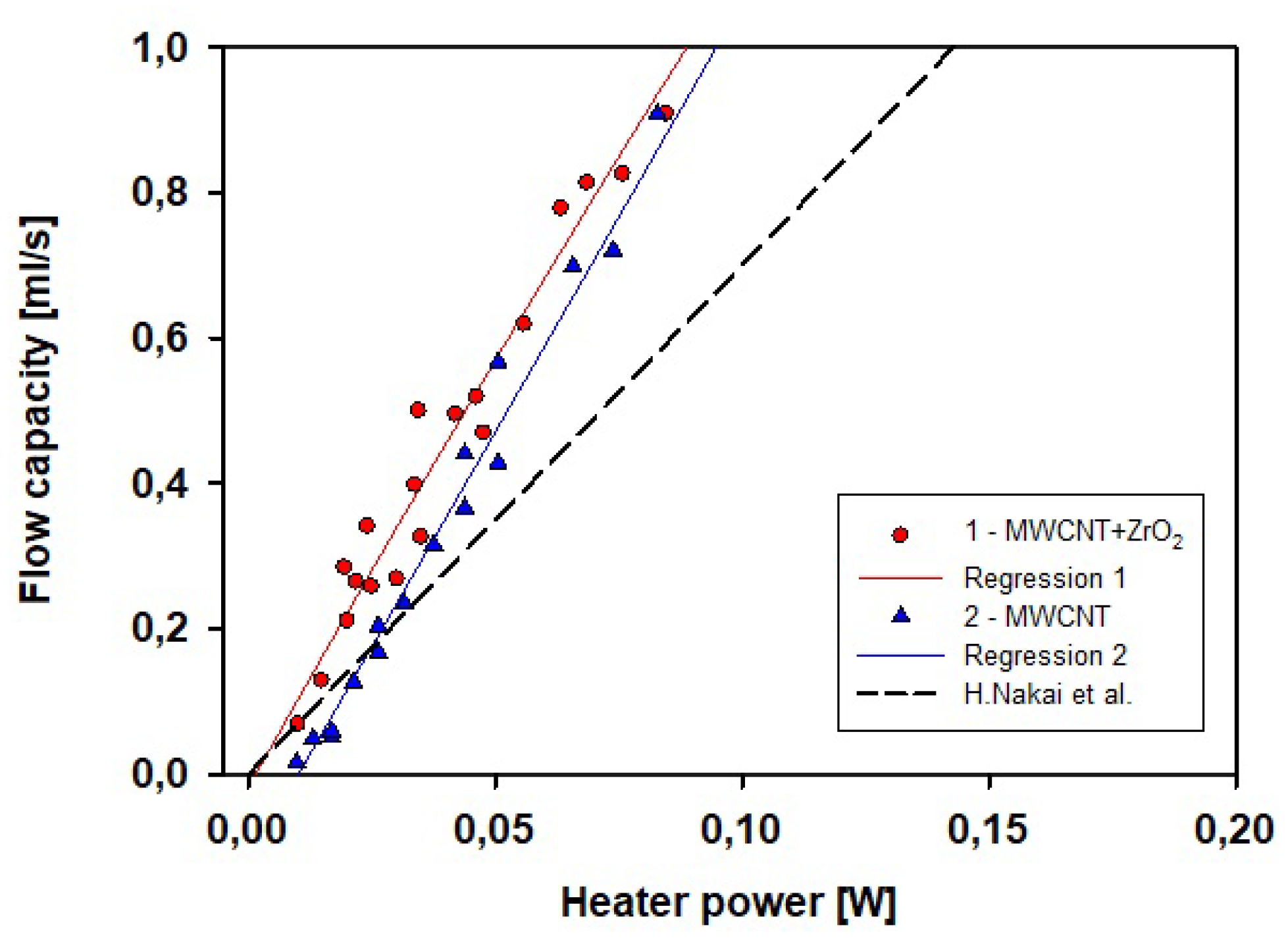
Figure 6 shows the comparison of the obtained results for purified MWCNTs and
/MWCNTs composites with the averaged results from research by H. Nakai team [
13] obtained at 1.8 K for the standard entropy filters made of
powders with varying grain size. Graph shows that the slope of the curve versus the power axis for the obtained series for MWCNTs was larger than that for
. This means a higher flow capacity of both types of MWCNTs filters.
Setup for the measurements of capacity of entropy filters was prepared for the filtration process working with a certain amount of helium. Due to this, the enrichment of the LHe mixture in
He was possible only to a limited extent—approximately 2.3 kg of helium could be filtered (which translates to 20 liters of LHe). This particular experimental setup was already described in detail in our previous paper [
10].
The measurements of separation effectiveness were performed on the sample of
/MWCNTs. This was chosen after the comparison of the filter flow capacity test results for an entropy filter composed of purified MWCNTs and the one composed of
/MWCNTs composite—see
Figure 6. Analysis of the regression lines showed that the line for the latter sample starts almost exactly at zero. This means that thermomechanical pump works even for the lowest applied power. This allows for the smooth (not jumpy) regulation of flow until reaching the final parameters of the filtration process — during the experiment, it was crucial to precisely control the pressure downstream of the entropy filter.
Two series with different levels of thermal excitation of the fountain effect were registered. Results are presented in
Figure 7 and
Figure 8. Concentration measurement was performed on a QMS700 spectrometer. Exemplary results of the
He concentration measurement at the beginning and in the intermediate stage of the filtration effectiveness are shown in
Figure 7a,b. The QMS700 spectrometer allows for detection of
ppm of
He, but due to the relatively high background level, as shown in
Figure 7, the experimental assumed error was at the level of
ppm (too low to mark in
Figure 8).
Figure 7 presents
He concentration measurements for two stages of the experiment: initial with
He concentration of 0.2 ppm (
Figure 7a) and one of the intermediate stages of the enrichment process (
Figure 7b), where
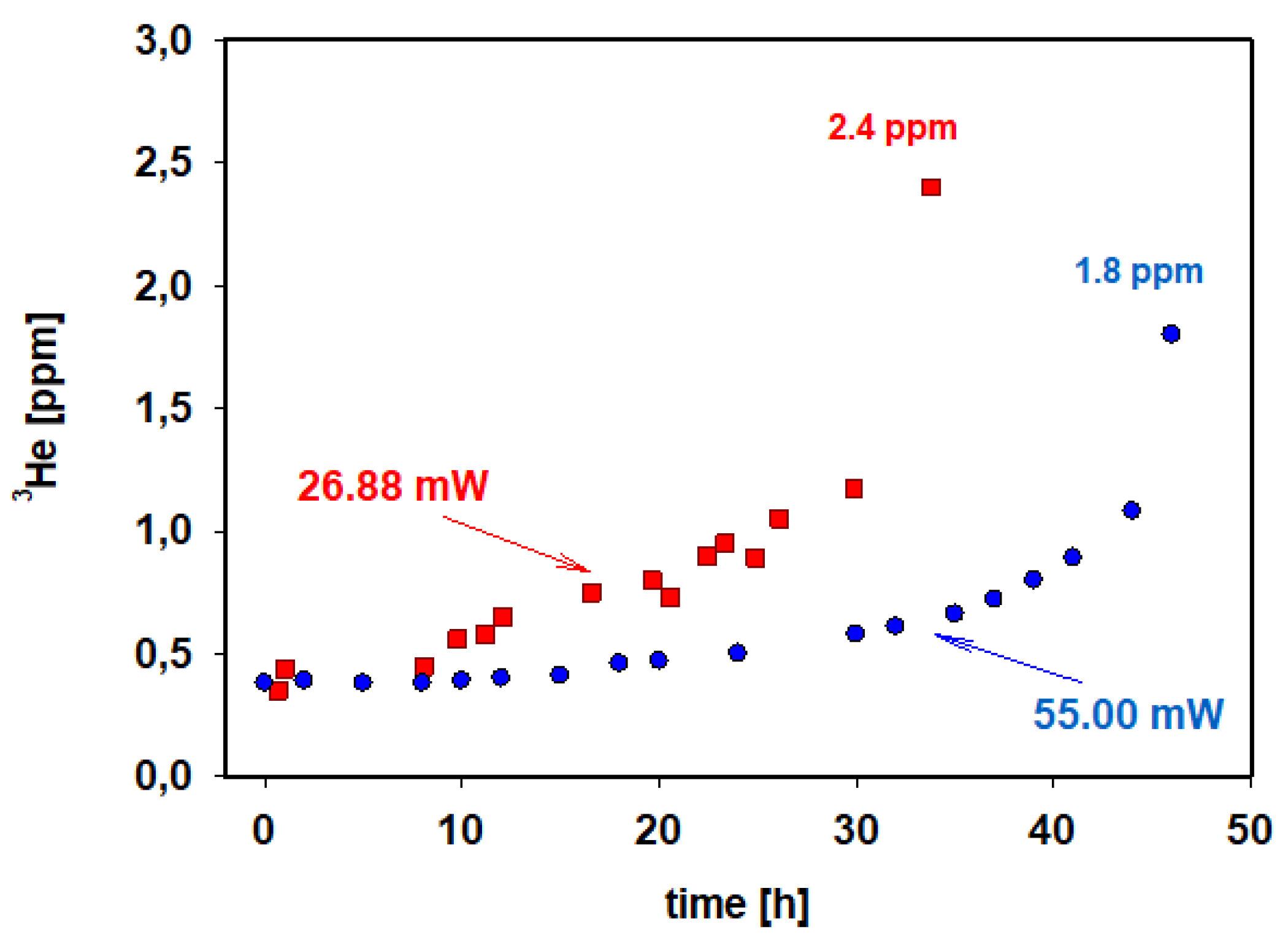
He concentration increased to 1.1 ppm. Results of two experiments showing the increase in
He concentration during the operation of entropy filter in different experimental conditions are presented in
Figure 8. An experiment was conducted with heater power of 26.88 mW, and the second with 55.00 mW.
Initial level of
He concentration for both processes presented in
Figure 8 is ≈0.4 ppm, which is higher than the one showed earlier for the unprocessed
He-
He mixture (≈0.2 ppm). This is because, before starting to gather samples for mass spectrometry,
He concentration slightly increased during the process of cooling the system by the capillary, which is the part of heat exchanger (Stages 3–6 in
Figure 5). Results for different power levels used, presented in
Figure 8, significantly differed: the application of the lower exciting power resulted in the higher concentration obtained in a shorter time. This is the result of the apparently crucial way of the regulation and stabilization of upstream and downstream pressure in the entropy filter. The upstream filter pressure was the same as in the whole helium container containing the enriched
He-
He mixture. During the experiment, this pressure was stable for the chosen temperature. Downstream filter pressure strongly depended on the flow rate of the superfluid component. Increasing the flow rate made it more difficult to maintain stable conditions downstream of the filter although, for all used power levels, the flow was still in the laminar regime (compare with
Figure 6). The downstream filter pressure controls the rate of the removal of filtered
He from the system, so its increase should lead to a more effective process. However, increasing flow capacity with a higher heating level (55.00 mW case) results in a sudden uncontrollable increase in pressure downstream of the filter, which led to a excited flow and worsened the filtration conditions. Lastly, both time and concentration were better for gentler conditions.
6. Conclusions
Our method of increasing the concentration of He in the He-He mixture, utilizing composite entropy filters in connection with careful control of filtration process conditions, is an important point on the roadmap to the future production of significant amounts of He, which is increasingly desirable for various purposes. This method, after improvements, could relatively easily be introduced into large installations producing LHe, which is a huge advantage over other, more exotic ways, for example, the extraction of He from the Moon’s surface.
Quantum filtration utilizing entropy filters made from carbon-based materials is especially interesting because these materials can be obtained in various forms and with strict control over their morphology [
22,
23], which in turn might lead to the increase in the effectiveness of described process.
The presented results in
Figure 8 suggest that there is an excitation power for which the filtration process is most effective. The determination of this optimal power level is one of our future goals.


 ,
, 


