Article

Creep Rupture and Permeability Evolution in High Temperature Heat-Treated Sandstone Containing Pre-Existing Twin Flaws

1
State Key Laboratory for Geomechanics and Deep Underground Engineering, School of Mechanics and Civil Engineering, China University of Mining and Technology, Xuzhou 221116, China
2
Department of Energy and Mineral Engineering, EMS Energy Institute and G3 Center, Pennsylvania State University, State College, PA 16802, USA
3
State Key Laboratory of Mining Response and Disaster Prevention and Control in Deep Coal Mines, Anhui University of Science and Technology, Huainan 232001, China
*
Author to whom correspondence should be addressed.
Energies 2021, 14(19), 6362; https://doi.org/10.3390/en14196362
Submission received: 13 August 2021 / Revised: 12 September 2021 / Accepted: 21 September 2021 / Published: 5 October 2021
(This article belongs to the Collection State of the Art Geo-Energy Technology in China)

Abstract

:
Utilizing underground coal gasification cavities for carbon capture and sequestration provides a potentially economic and sustainable solution to a vexing environmental and energy problem. The thermal influence on creep properties and long-term permeability evolution around the underground gasification chamber is a key issue in UCG-CCS operation in containing fugitive emissions. We complete multi-step loading and unloading creep tests with permeability measurement at confining stresses of 30 MPa on pre-cracked sandstone specimens thermally heat-treated to 250, 500, 750 and 1000 °C. Observations indicate a critical threshold temperature of 500 °C required to initiate thermally-induced cracks with subsequent strength reduction occurring at 750 °C. Comparison of histories of creep, visco-elastic and visco-plastic strains highlight the existence of a strain jump at a certain deviatoric stress level—where the intervening rock bridge between the twin starter-cracks is eliminated. As the deviatoric stress level increases, the visco-plastic strains make up an important composition of total creep strain, especially for specimens pre-treated at higher temperatures, and the development of the visco-plastic strain leads to the time-dependent failure of the rock. The thermal pre-treatment produces thermal cracks with their closure resulting in increased instantaneous elastic strains and instantaneous plastic strains. With increasing stress ratio, the steady-state creep rates increase slowly before the failure stress ratio but rise suddenly over the final stress ratio to failure. However, the pre-treatment temperature has no clear and apparent influence on steady creep strain rates. Rock specimens subject to higher pre-treatment temperatures exhibit higher permeabilities. The pre-existing cracks close under compression with a coplanar shear crack propagating from the starter-cracks and ultimately linking these formerly separate cracks. In addition, it is clear that the specimens pre-treated at higher temperatures accommodate greater damage.

1. Introduction

Underground coal gasification (UCG) is a technology that converts hydrocarbons into syngas in-situ [1,2]. Crucially, UCG combined with carbon capture and sequestration (CCS) may have a special promise [3]. While UCG-CCS has potential promise, some key environmental and engineering issues require resolution. We focus on key rock mechanics problems including excessive subsidence and fugitive gases—each critically impacted by the response of strength and permeability to the imposed high temperatures. Similar to long-wall mining, excavation of coal from depth may cause subsidence, especially over long-term operations and under high crustal stress. It ought to be possible to inject CO2 into former UCG voids which are currently at a depth of more than 800 m [4]. The UCG process is intensely exothermic with the temperatures occasionally exceeding 900 °C in the combustion zone. Prior observations indicate that high temperatures significantly transform the physical and chemical properties and resulting mechanical behavior of rocks (e.g., heating and quenching the first caprock may result in cracking or other behavior that compromises the integrity of the storage [5]). In addition, the high permeability of the UCG goaf for geological CCS projects, CO2 storage in artificially developed UCG goaf with high permeability appears to be an attractive proposition [4], provided storage security of the caprocks can be guaranteed.
Heat transfer mechanisms in rocks are complex and nonlinear [6,7,8,9,10,11]. UCG production boreholes typically experience extreme temperatures of the order of ~900 °C which significantly exceeds the critical temperature (Tc~400–500 °C) that induces changes in the mechanical and permeability behavior of typical sandstones [11]. Temperatures from ambient to 400 °C correspond to vaporization then escape of adhered water, combined water and structural water. Between 400–600 °C, the minerals in the sandstone thermally react and transform, resulting in porosity increase, reduction in permeability and diffusivity, and changes in heat capacity [12]. Reservoir rheology is also sensitive to temperature [6,13,14]. An increase in temperature accelerates creep strains and consequently reduces the time-to-failure [15]. The total axial strain increases with increasing temperature, with instantaneous elastic strain and instantaneous plastic strain increasing slightly as the temperature increases from 25 to 700 °C but then increasing substantially as the temperature reaches 1000 °C [16]. However, the response of fractured rocks is usually different from that of intact rock—since stress concentrations are present at the ends of pre-existing cracks—promoting the initiation of new cracks and the reduction in rock mass strength [17,18]. Previous investigations [19,20,21,22] addressed crack initiation and coalescence for jointed rock masses under short-term loading with key mechanisms of creep contributing to time-dependent deformation and crack propagation [23,24]. Investigation of time-dependent response of jointed rock [21,25,26,27,28] have defined key failure mechanisms but few characterizations study the comprehensive impact of thermal effects on time-dependent interaction of thermal cracking across the scales.
The high-temperature treatment of the rock mass during underground coal gasification leads to the formation of fractures and changes in the fluid transmission characteristics of the strata, which is a direct result of the combustion process [29]. Thermal cracks result and increase permeability as the temperature increases from 400–600 °C [10]. Prior observations have promoted our understanding of permeability evolution due to short-term heating and loading demonstrating a linear correlation with volumetric strain [24,30]. However, the timescales of permeability evolution of the goaf in UCG-CCS operations should also be noted. During creep loading the permeability will typically decrease before increasing with the onset of failure at late deformation stages [28,30]. Some observations reveal that the temperature effects are on timescales of permeability evolution and that during the multi-step loading and unloading cycles process the permeability first decreases slightly as temperature increases from 25 to 300 °C and then increases with increasing temperature [28]. Heating rate significantly affects thermal damage as evident in that permeability is exponentially correlated with the number of AE events [24].
Consequences of the combined presence of pre-existing fissures, high confining pressures and high temperatures on the evolution of strength and permeability for UCG-CCS operations has not been previously considered. Correspondingly, the following focuses on defining the influence of thermal damage on creep properties and permeability evolution of pre-cracked specimens of red sandstone from micro-scale to laboratory scale. The primary focus is to identify creep parameters and overall permeability evolution in the pre-cracked rock in response to different pre-treatment temperatures in defining characteristics of the evolution of transport properties and mechanical strength.

2. Experimental Materials and Procedures

2.1. Sandstone Specimens and Heating Procedure

The red sandstone used for these experiments was collected from Rizhao City in Shandong Province, China. The dry density is 2402 kg/m3, and effective porosity is ~6.26–6.55% [28]. The sandstone mainly comprises quartz, feldspar, dolomite, hematite and clay minerals. The tested specimens were cylindrical with 50 mm in diameter and 100 mm in height. Then, two fissures of near-identical length (2a = 12 mm) and width (d = 2 mm) were cut in the specimens by diamond wire saw. The inclination angle of two coplanar cracks was 45° with an intervening rock bridge of 2b = 12 mm. The samples were dried for ~24 h and then heated to 250, 500, 750 and 1000 °C at a rate of 5 °C/min. The specimens were held at their target temperature for two hours before cooling naturally to room temperature (Figure 1). The color of the specimens changed as a result of the heat-treatment changing from drab-red (250 °C), progressively redder (500 and 750 °C) before becoming brown at 1000 °C.
Figure 2 shows SEM images of the red sandstone after different pre-treatment temperatures. At 250 °C (Figure 2a), minor micro-cracks appear, and these develop into boundary cracks at the edges of grains during thermal cooling and differential expansion/contraction (Figure 2b,c). In addition, some transgranular cracks appear across grains. When the temperature reaches 1000 °C (Figure 2d) the density of boundary cracks increases and the crack apertures between grains also increases. The number of transgranular cracks also increases significantly. The results indicate a threshold temperature to produce thermally induced cracks in this study is 500 °C.

2.2. Testing Procedure

Conventional triaxial compression and multi-step loading- and unloading-cycle creep tests were completed under a confining pressure of 30 MPa (Figure 3a). The test system consists of three servo-hydraulic control units applying: axial, confining pressure and pore pressure loads. The maximum axial loading capacity of testing system is 800 kN, and the maximum confining pressure and pore pressure can reach 60 MPa. The axial deformation of the specimen was measured with a pair of linear variable displacement transducers (LVDTs), and the circumferential deformation was measured with a circumferential extensometer (Figure 3b).
The conventional triaxial compression tests were first completed to obtain the peak strength of the double pre-cracked sandstone specimens after exposure different temperature treatments. The test procedure is as follows: (i) at a loading rate of 4 MPa/min, 30 MPa hydrostatic pressure was applied to the specimen; (ii) then the specimen was axial loaded at a rate of 0.04 mm/min until it reached the residual strength. The stress-strain curves and triaxial compressive strengths (TCS) were thereby obtained.
Multi-step loading- and unloading-cycle creep tests were subsequently completed to study the creep characteristics of the pre-cracked sandstone. Stress levels for the creep tests were set according to the TCS. The test procedure was as follows: (i) the specimens were subjected to 30 MPa hydrostatic pressure at a rate of 4 MPa/min; (ii) a pre-determined first stress level was applied under pressure-controlled condition of 5 MPa/min; (iii) the specimen was then allowed to deform for approximately 48 h under constant stress; (iv) the axial deviatoric stress was then unloaded to 0 MPa under pressure-controlled conditions of 5 MPa/min; (v) these unloading conditions were retained for 24 h. Next, these loading and unloading cycles to creep were repeated until creep failure occurred. During the test, the axial and lateral strains of the pre-cracked red sandstone specimens were recorded continuously. The basic physical parameters of the specimens are listed in Table 1 with each of the deviatoric stress levels shown in Table 2.
With inert nitrogen as the flow medium, the permeability of pre- cracked specimens was measured by steady-state flow method during the creep test. The gas pressures at upstream and downstream were 3 MPa and 0.1 MPa, respectively. The permeability was calculated from Equation (1).
k = Q μ L 2 p d A ( p u 2 p d 2 )
where Q represents volumetric gas flow rate (m3/s), μ represents the viscosity of the nitrogen (Pa·s); L and A represent the length (m) and the cross-sectional area (m2) of the rock specimen, respectively; Pu and Pd represent the inlet and outlet gas pressures (MPa), respectively. We observe that as the temperature increases the elastic modulus decreases and the Poisson’s ratio overall increases (Table 1).

3. Experimental Results and Discussion

3.1. Creep Test Results

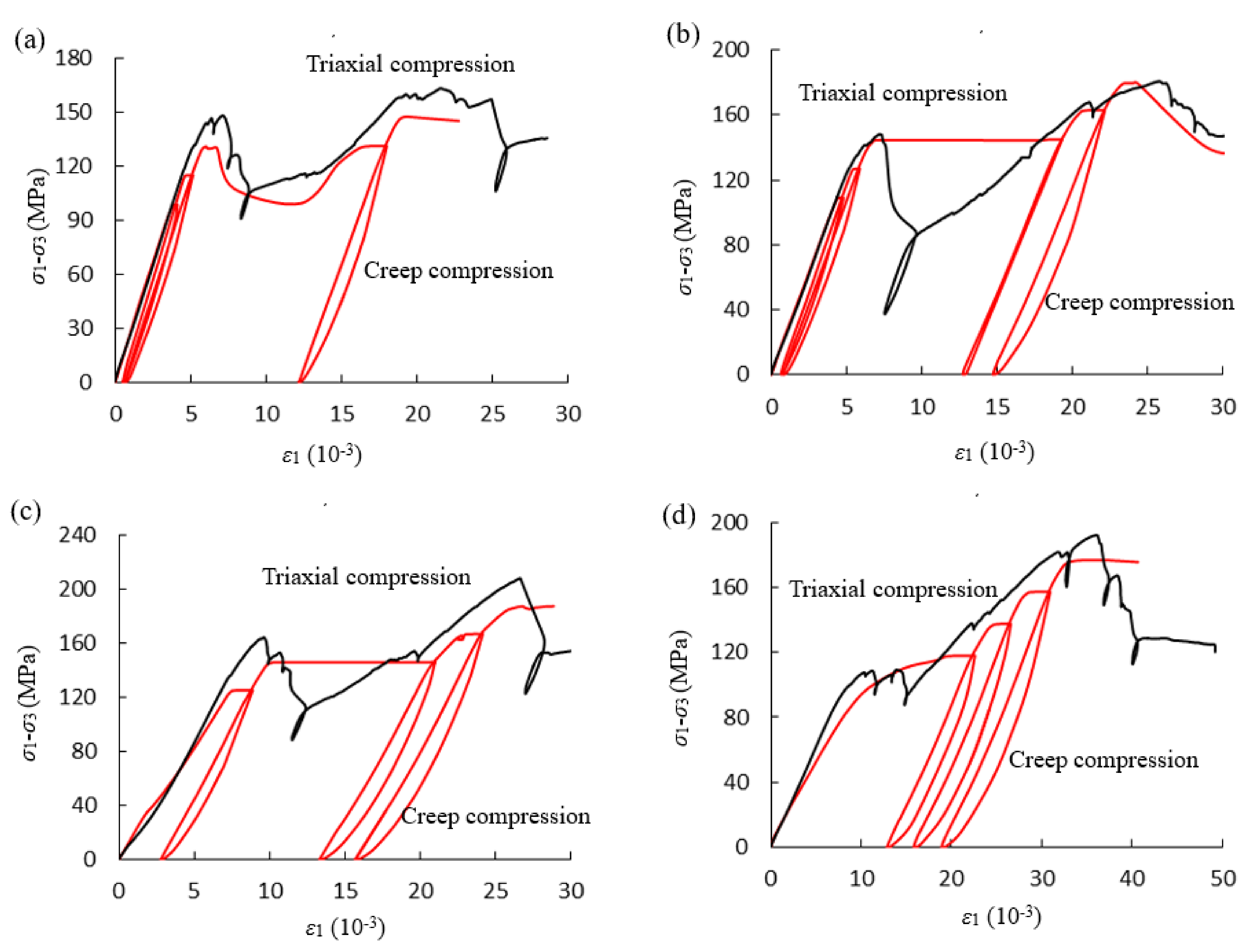
The axial deviatoric stress-strain curves of the pre-cracked sandstone specimens under conventional triaxial compression and cyclic creep compression are presented in Figure 4. The peak strength obtained from the cyclic creep compression is lower than that obtained from conventional compression for the different pre-treated temperatures. The creep curves plateau at each stress level, representing creep deformations under each constant stress. Each loading produced plastic deformation, with the plastic deformation increasing with an increase in the deviatoric stress. In addition, as with the increases in stress levels, the length of the stress-plateau also gradually increases, except a certain threshold stress level where coalescence of two coplanar cracks produced a larger plastic deformation, such as Figure 4a–c. A stress drop occurs after reaching the first peak strength due to the closure of the pre-existing cracks. This is because the ensemble closure of the pre-existing cracks and newly formed fractures increases the load capacity of the specimen. The resulting second peak strength was always larger than the first peak strength due to this closure of the pre-existing cracks. It should be noted that this double peak strength phenomenon is different from that for intact specimens that show only a single peak strength because intact specimens without pre-existing cracks the plastic hardening is not obvious [28,30].
Figure 5 illustrates the variations in the axial and lateral strains over time for the pre-cracked specimens for different pre-treatment temperatures subject to multi-level creep loading and unloading. Instantaneous axial and lateral strains are produced as the deviatoric stress is applied with the elastic strains recovered as the deviatoric stress is removed. The increasing number of loading and unloading cycles will lead to more unrecoverable axial deformation, especially at a certain level of deviatoric stress that causes the closure of pre-existing cracks and produces large irrecoverable deformations, such as the bule dotted oval in Figure 5a–c. When the target deviatoric stress was reached, the deviatoric stress remained constant for 48 h. When the stress level is relatively low, deceleration deformation and steady creep deformation are the main components of axial deformation. As the deviatoric stress increases, the duration of the primary creep tends to increase, and when the deviatoric stress exceeds a threshold stress level, a fracture propagated between the two colinear cracks, producing a large plastic deformation. For instance, the specimens pre-treated to 250 and 500 °C (Figure 5a,b) fractured during the 3rd stress level while the specimen exposed to 750 °C (Figure 5c) fractured during only the 2nd stress level. Whereas primary, secondary and tertiary creep occurred under creep failure stress levels, as shown in the red dotted oval. The unloading deviatoric stress was 0 MPa since the elastic hysteretic behavior of rock maintained unloading conditions for 24 h.

3.2. Strain Separation

During creep experiments, the specific strains are separated by cyclic loading and unloading, including components of both recoverable strain and irrecoverable strain. The recoverable strain consists of the instantaneous elastic strain (εme) and visco-elastic strain (εve), whereas the irrecoverable strain is composed of the instantaneous plastic strain (εmp) and visco-plastic strain (εvp), as shown in Figure 6. Moreover, total strain (ε) can also be divided into instantaneous (εm) and creep (εc) strains, which can be expressed as
ε = ε m + ε c
The instantaneous strain εm is the measured strain when the targeted deviatoric stress level is reached and the creep strain εc refers to the increase of strain measured with time at the stage of constant loading. The instantaneous strain εm is composed of two parts, i.e., the instantaneous elastic strain εme and the instantaneous plastic strain εmp:
ε m = ε m e + ε m p
The creep strain εc also consists of two parts, the recoverable visco-elastic strain εve and the unrecoverable visco-plastic strain εvp:
ε c = ε v e + ε v p
The duration of the creep loading is often longer than the duration of unloading—for instance, in this present study, the duration of the loading stage is 48 h, while the duration of unloading is 24 h. Hence, no visco-elastic recovery data are available from unloading for only 24 h. To obtain the visco-plastic strains under different stress levels, the visco-elastic strains based on experimental results were fitted by Equation (5). Then, the difference between the creep strain and the fitted visco-elastic strain may be evaluated as the visco-plastic strain under the loading conditions [16].
ε v e = A 1 exp B t m
where A, B and m are fitting parameters (m > 0).
Due to accelerated creep failure, the visco-elastic strain and visco-plastic strain in the third creep cannot be separated. and the tertiary creep should be represented by coupling visco-plasticity to damage [31,32,33]. In this study, the deformation after failure of the specimen is considered irreversible and the entire creep strain is taken as the visco-plastic strain.
The creep strain histories of the thermally-treated pre-cracked specimens are separated into visco-elastic and visco-plastic strains according to the prior separation method. The variation of the total creep strains, visco-elastic strains and visco-plastic strains with time for four specimens are plotted in Figure 7 (the subfigure in dashed box is the enlarged version of the dashed part in main figure). For the specimen pre-treated at 250 °C (Figure 7a), there are 4 levels of deviatoric stress in total. The creep and visco-plastic strains can be characterized by primary creep and steady-state creep during the 1st and 2nd deviatoric stress levels. At the 3rd deviatoric stress level, as a result of crack growth, the creep strain and visco-plastic strain rates gradually increases until 95.597 h when the rock bridge between the two cracks fractures. At that point, the strain rate decreases, and begins steady-state creep at 95.61 h. At the 4th deviatoric stress level, because the ultimate failure of the specimen, the creep strain cannot be separated—therefore, it is considered that the creep strain is equal to the visco-plastic strain. The creep strain sequence can be characterized into primary, steady-state and tertiary creep. The visco-elastic strain can be characterized as primary and steady-state creep over the 1st stress interval and as primary creep from the 2nd deviatoric stress level. It should be noted that, the creep strain curves of the 3rd and 4th deviatoric stress levels are different: the creep rate under the 3rd deviatoric stress level first increases, and then decreases; however, the creep rate under 4th deviatoric stress level is opposite and is characterized by a typical creep curve.
The separated strains for the specimen pre-heated to 500 °C are shown in Figure 7b. The results are similar to that for the 250 °C heated specimen as the creep and visco-plastic strains show both primary and steady-state creep at the 1st to 2nd deviatoric stress levels with a strain jump at the 3rd deviatoric stress level. At the 4th deviatoric stress level, the creep and visco-plastic strains are larger than those at the 1st and 2nd deviatoric stress level but smaller than at the 3rd deviatoric stress level that exhibits primary and steady-state creep. As the deviatoric stress is increased, the primary creep, steady-state creep and tertiary creep clearly exhibit at the 5th deviatoric stress level when the specimen finally fails during tertiary creep.
Figure 7c shows the separated strains for the 750 °C treatment. The creep strain curve and the visco-plastic strain curve are characterized by primary and steady-state creep at the 1st deviatoric stress levels but with very small strain rates of steady-state creep. The visco-elastic strains are lower than the visco-plastic strains at the 1st deviatoric stress level. At the 2nd deviatoric stress level, in the initial loading stage, the creep and visco-plastic strain increases rapidly, but the rate of increase decreases until 47.5 h when the creep and visco-plastic strain jump from 0.85 × 10⁻³, 0.83 × 10⁻³ to 10.37 × 10⁻³, 10.33 × 10⁻³, respectively, but the visco-elastic strain only increases from 0.027 × 10⁻³ to 0.042 × 10⁻³, before establishing a steady-state. The specimen ultimately fails at the 4th deviatoric stress level after 0.11 h.
The separated strains for the 1000 °C specimen are different from the previously noted specimen behaviors (Figure 7d). First, the creep and visco-plastic strains are larger than those for specimens pre-heated to 250, 500 and 750 °C. Secondly, as the creep progresses, the creep and visco-plastic strains increase smoothly and progressively with no strain jump occurring until final failure. This results from the damage produced by the intense thermal cracking—during creep loading, closure of these cracks consumes most of the strain energy with insufficient remainder to fracture the rock.
Comparison of histories of creep, visco-elastic and visco-plastic strains highlight the existence of a strain jump at a certain deviatoric stress level—where the intervening rock bridge between the two starter-cracks fractures. However, the joining of these pre-existing cracks does not result in complete failure, but merely produces a larger irreversible visco-plastic strain with reduced ultimate strength. As the deviatoric stress level further increases, the visco-plastic strain accounts for an important proportion of total creep strain, especially for the high pre-treatment temperature specimens, with the development of the visco-plastic strain leading to the time-dependent failure of the rock.

3.3. Pre-Treatment Temperature Effects

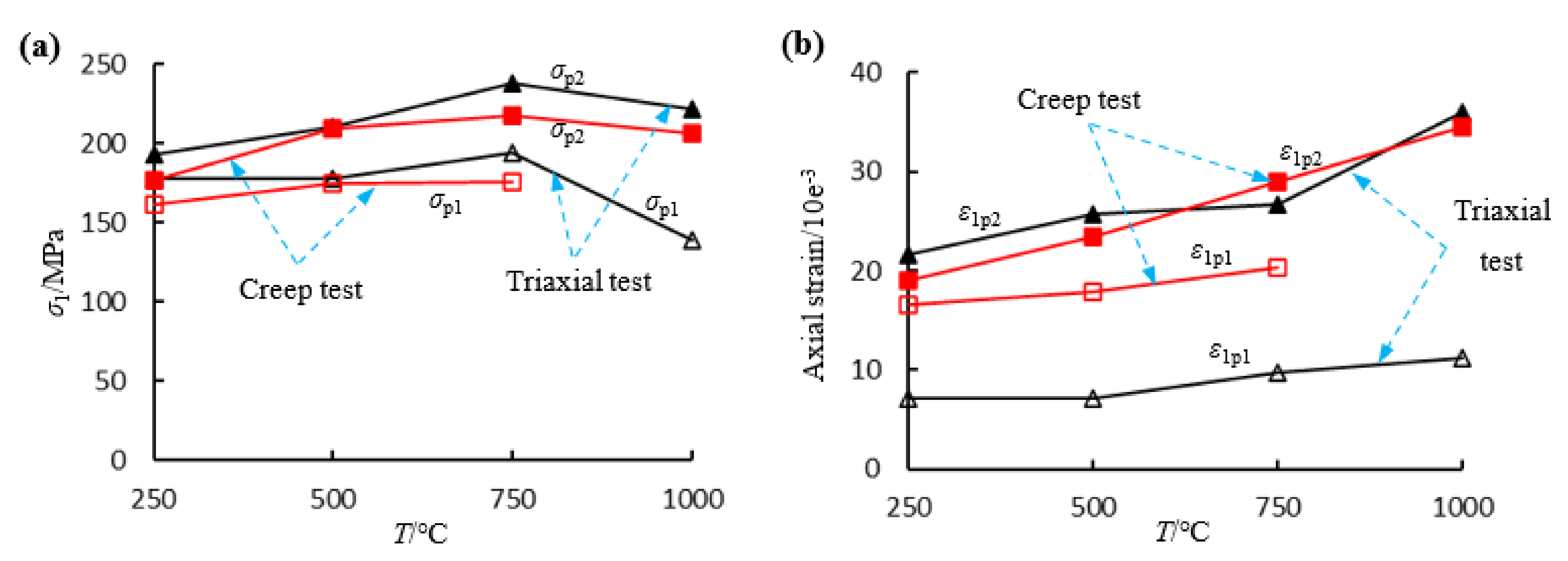
These specimens exhibit dual peak strengths in compression as a result of the twin coplanar flaws (Figure 4), as illustrated by the corresponding axial strain versus pre-treatment temperature in Figure 8. Figure 8a shows the two peak strengths obtained from both the triaxial and creep tests both increase as the temperature increases from 250–750 °C, but then decreases substantially as temperatures reach 1000 °C. The principal reason for this is the vaporization and escape of adhered water, combined water and structural water between temperatures of 250–750 °C, which leads to an increase in the coefficient of internal friction [11] and increase in strength. When the temperature reaches 1000 °C, boundary and transgranular cracks develop and intergranular cracks widen—again resulting in a reduction in strength. In addition to its influence on ultimate strength, thermal treatment also has a influence on the deformation characteristics. Figure 8b shows changes in the peak strains with pre-treatment temperature. The axial strain at both peak strengths increase with pre-treatment temperature as it increases from 250 to 1000 °C.
To better characterize the effects of temperature on different separated strains, those strains are plotted against stress ratio for different pre-treatment temperatures Figure 9 and Figure 10. Figure 9 shows the variation in the instantaneous elastic strains and the instantaneous plastic strains with stress ratio for the four pre-treatment temperatures. It is apparent from Figure 9a that the instantaneous elastic strains of the pre-cracked specimens increase linearly with an increase in the stress ratio. The instantaneous elastic strains increase with pre-treatment temperature, for example, the difference in value a between 250 °C and 500 °C is less than the difference in value b between 500 °C and 750 °C, and both are significantly less than the difference in value c between 750 °C and 1000 °C. Figure 9b illustrates the variation of instantaneous plastic strains with stress ratio showing that between 250~750 °C there is no obvious change with the initial stress ratio. However, when reaching the stress level for fracture, the instantaneous strain increases significantly due to the closure of pre-existing cracks. The instantaneous plastic strain of the specimen under a treatment temperature of 1000 °C is relatively large due to the closure of thermally-induced cracks with the instantaneous plastic strain increasing with an increase in the stress ratio.
From the above analysis, the instantaneous elastic deformation is usually larger than the instantaneous plastic deformation, but the closure of pre-existing cracks and the fracture of rock bridges produces a large plastic deformation that presents unconventional response. The instantaneous plastic strain exceeds any instantaneous elastic strain when closure and fracture occur. The thermal pre-treatment produces thermal cracks with their closure resulting in increased instantaneous elastic strains and instantaneous plastic strains.
Figure 10 shows the evolution of the visco-elastic and visco-plastic strains with stress ratio. The visco-elastic strains increase nonlinearly with an increase in the stress ratio and exhibit a complex relationship with temperature. The visco-elastic strains of the pre-cracked specimen after pre-treatment at 250 and 500 °C are almost equal, but smaller than that of the specimen pre-treated at 750 °C. However, as the pre-treatment temperature increases to 1000 °C, the visco-elastic strain is less than that for the specimen pre-treated at 750 °C because a larger irreversible plastic deformation is produced by the closure of thermally-induced cracks of the specimen pre-treated at 1000 °C. The visco-plastic strain apparent in the 1000 °C specimen (Figure 10b) also supports this—the visco-plastic strain of this hot specimen is larger than that for lower temperatures, except at certain stress ratios where the closure of pre-cracks and fracturing of the rock bridge causes a significant plastic deformation.
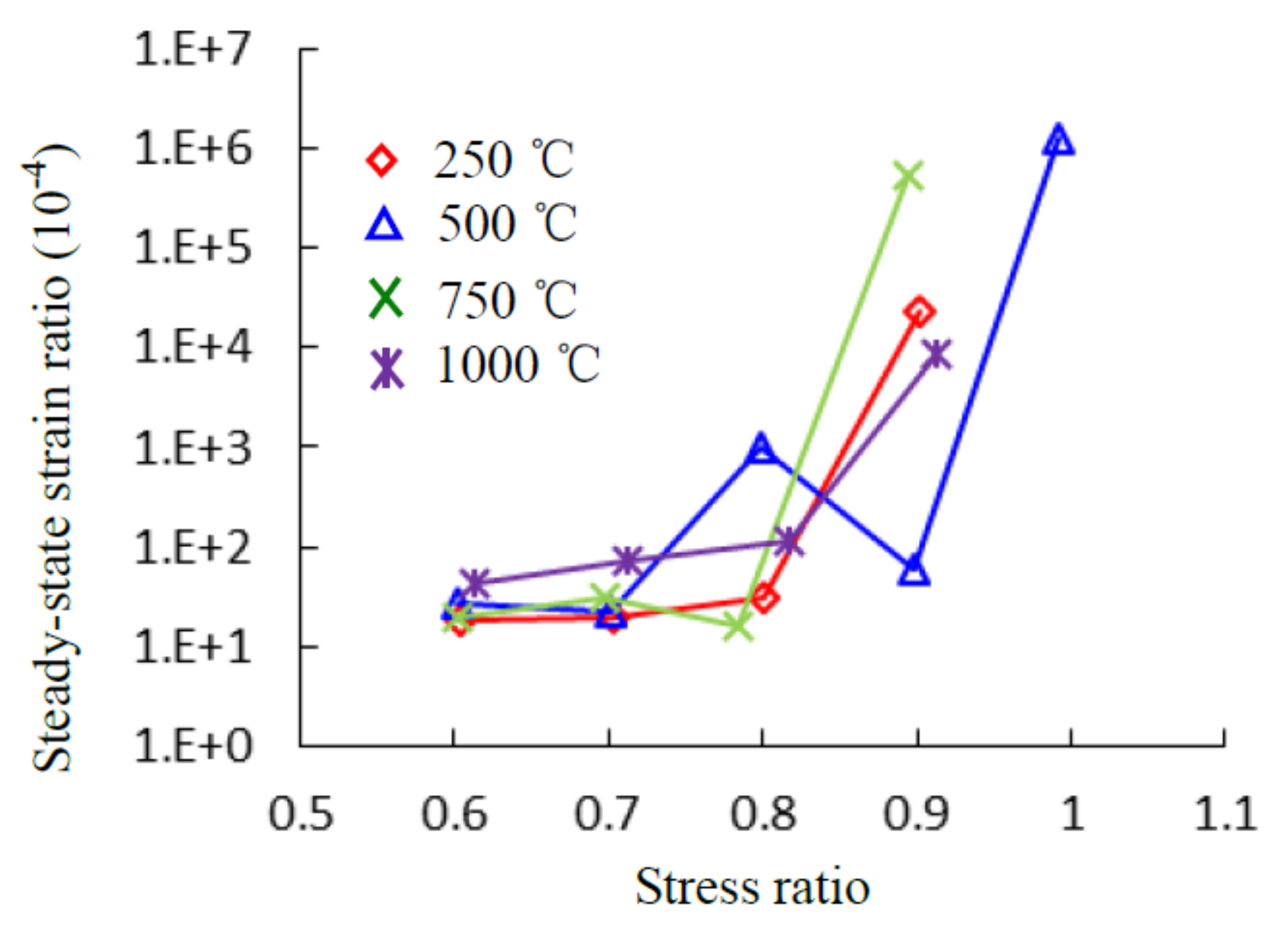
The creep strain rates during steady creep can be obtained by taking the derivative of steady creep curves, considered as of constant gradient. Figure 11 shows the steady-state creep strain rate versus stress ratio for all tested specimens. The results show that the steady-state creep rates increase slowly with stress ratio before the failure stress ratio but rise suddenly over the final stress ratio. The steady-state creep strain rate over the last stage is usually several orders of magnitude larger than that of the previous stages—requiring the use of logarithmic rates. The pre-heated temperature has no clear nor apparent influence on steady creep strain rates.
The degree of material deterioration under changing stress states can be quantitatively described by the damage variable (D) [34]. Usually, D can be calculated using the elastic modulus, ultrasonic wave velocity, density and indexed to energy adsorption, strain and acoustic emission [35]. However, in cyclic loading-unloading creep tests, instantaneous elastic and visco-elastic strains are recovered after unloading, but instantaneous plastic and visco-plastic strains are not. Hence, the damage variable may be calculated using the ratio of non-elastic strain (instant plastic strain and visco-plastic strain) to total strains. Finally, D can be calculated from the instantaneous elastic and visco-elastic strains as [28]:
D = 1 ε e ε = 1 ε m e + ε c v e ε m + ε c = ε m p + ε c v p ε m + ε c
where εe and ε are the elastic and the total strains, respectively; εme and εcve represent the instantaneous elastic and the visco-elastic strains, respectively; εmp and εcvp represent the instantaneous plastic and the visco-plastic strains, respectively; and εm and εc represent the instantaneous and the creep strains, respectively.
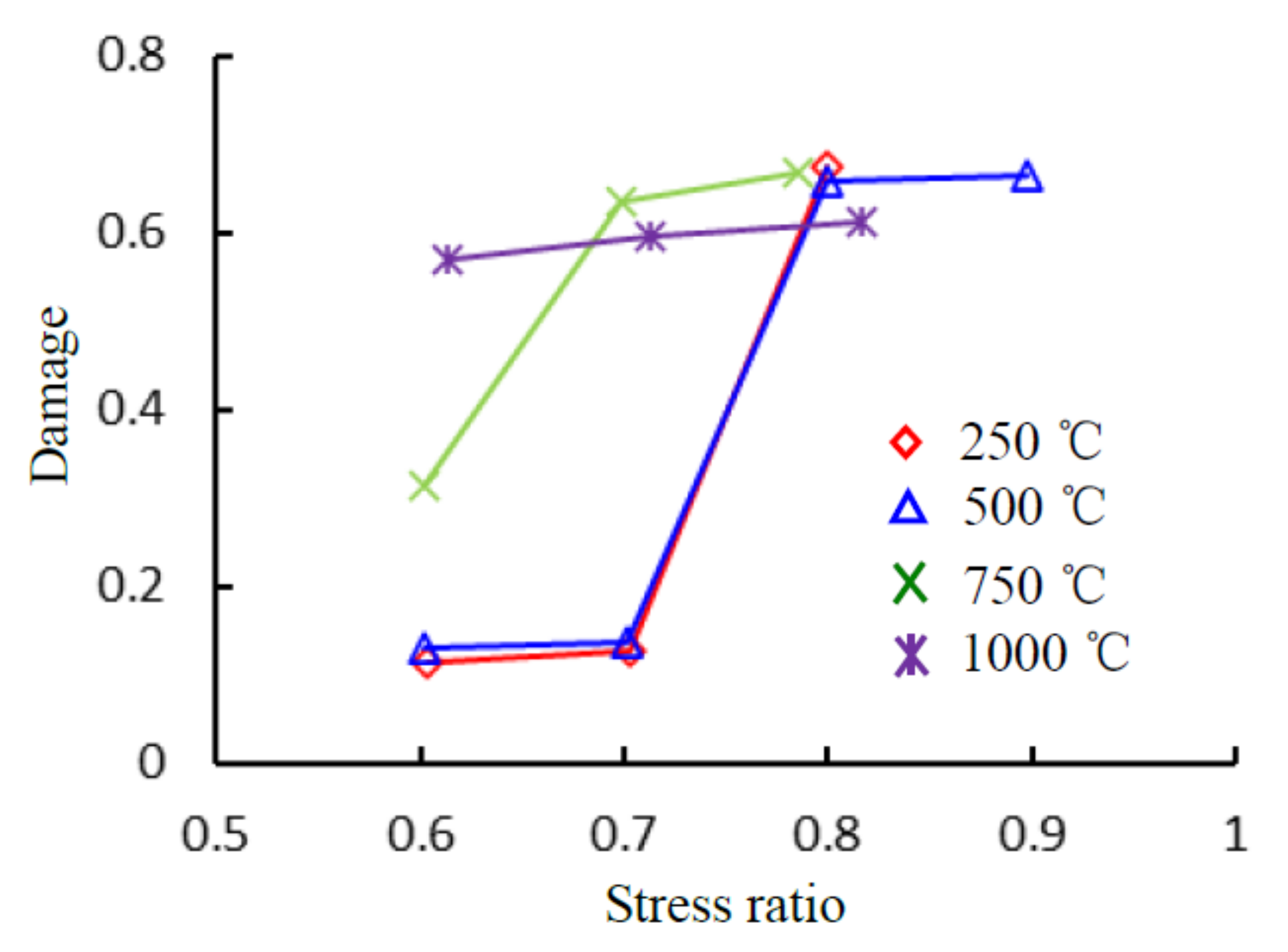
Figure 12 plots D against the different stress ratios (SRs). As SR increases, D also increases—the higher the stress level the greater the damage. This is especially true when the SR increases from 0.7 to 0.8 for the specimens pre-treated at 250 and 500 °C, and as SR increases from 0.6 to 0.7 for the specimen pre-treated at 750 °C where D increases sharply due to the closure of pre-existing cracks. For identical SRs, the specimen with the higher temperature pre-treatment usually accumulates the greater damage. For example, under a stress ratio of 0.6, the D of the specimen subjected to 1000 °C is 0.56 and is larger than the 0.31 for the 750 °C, and much larger than the 0.11 and 0.13 for the 250 and 500 °C specimens.

3.4. Permeability Evolution

The evolution of volumetric creep and gas permeability for pre-treatment temperatures of 250 and 500 °C is presented in Figure 13. Equation (1) is adopted to calculate the coefficient of permeability. Permeability is closely related to volumetric strain during the creep process. During cyclic loading and unloading creep tests (Figure 13a) the permeability of sandstone remains near constant at low deviatoric stress (first two stress) before slightly increasing with unloading. The volumetric strain during the 3rd deviatoric stress level sharply increases and then decreases, resulting in the permeability also first increasing before subsequently decreasing. This results from the closure of pre-existing cracks and the production of some new cracks, although the newly produced cracks subsequently close under compression. At the final deviatoric stress level, the volume of the sandstone specimen initially decreases but then dilates before failure—the permeability shows an inverse trend to that expected from the volume strain signal. When the specimen fails, macro-cracks are generated and the permeability increases. Figure 13b shows the relationship between volumetric strain and permeability for the specimen after pre-heating to 500 °C. The permeability of the pre-cracked sandstone decreases with loading and increases with unloading of the deviatoric stress (Figure 13b). This results from the re-opening of pre-existing pores and fissures. With an increase in the deviatoric stress from 293 MPa to 247 MPa, the permeability due to each loading and unloading creep cycle becomes progressively lower—this can be explained by the presumed material strengthening of the sandstone under cyclic loading [30]. Over the final deviatoric stress level, the large macroscopic cracks linking the starter cracks have already been formed and this precipitates structural failure of the specimen—the permeability then increases significantly to 45 × 10−18 m2.
Rock specimens undergoing hotter pre-treatments exhibit higher permeabilities. The average permeability of specimens pre-heated to 250 °C before failure is 5 × 10⁻¹⁸ m2 which is almost an order of magnitude lower than that for 500 °C (45 × 10−18 m2). The higher temperature pre-treatment produces more thermal cracks and provides more connected channels for gas transport.

3.5. Failure Modes

Failure modes are presented in Figure 14 showing the presence of a macro shear crack as indicative of failure with some tensile cracks induced by the shear sliding. The pre-existing cracks are closed under compression with a coplanar shear crack linking these formerly separate cracks. The pre-existing cracks exert a considerable influence on the creep failure mode in each specimen. In addition, it is clear that the specimens pre-treated at higher temperatures accommodate greater damage. For example, the shear fracture for specimens heated to 750 and 1000 °C is clearly wider than that for specimens pre-treated to 250 and 500 °C. In addition, the specimens undergoing higher temperature pre-treatments (Figure 14c,d) accumulated more severe damage than those at lower temperatures (Figure 14a,b)—apparent in the loss of some spalling along the main shear crack (Figure 14c,d).
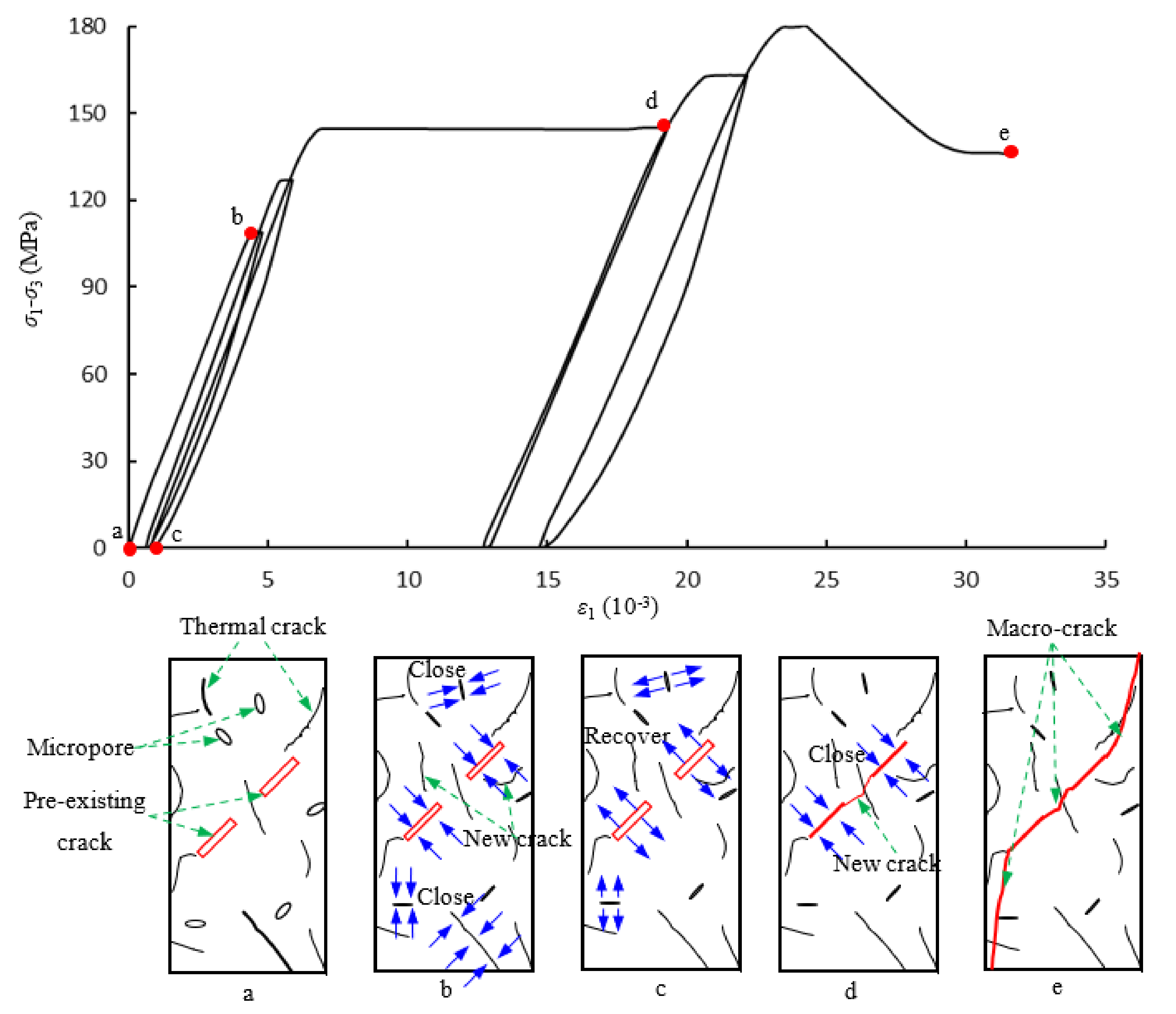
We choose five stages to describe crack evolution in the loading and unloading creep tests (Figure 15). Due to the interaction of thermal cracks (produced by high temperature) and pre-existing cracks, the crack evolution is more complex than that in isothermal un-treated intact specimens. Stage a represents the initial state with the specimen containing two coplanar pre-existing cracks dipping at 45° relative to the direction of the maximum principal stress. We conclude from Figure 2 that the specimen contains some thermal cracks and micropores. Stage b corresponds to the first level of loading. Under compression, the micropores and some thermal cracks close and produce a small number of cracks, but the stress is insufficient to cause wholesale fracture. Stage c is when the second unloading is completed. As the loading stress is removed, the closed micropores and cracks partially recover, elastically. Stage d produces a collapse as a stress concentration at the ends of the pre-existing cracks causes a new shear crack to connect the two pre-existing cracks. A large axial deformation results due to the closure of the pre-existing cracks. Stage e is the ultimate failure of the specimen. A macro-crack forms colinear to the pre-existing cracks, linking them, and which provides a connected channel for gas flow that yields a corresponding jump in permeability.

4. Conclusions

We report tightly constrained experiments on heat-treated specimens containing pre-exiting cracks to explore the evolution of creep rupture and the evolution of permeability in the rock surrounding heated underground gasification chambers. Multi-step loading and unloading creep tests with concurrent measurement of gas permeability were completed under a confining pressure of 30 MPa. The following conclusions are drawn based on the experimental results.
(1) The SEM results indicate that the threshold temperature that is required to produce thermally induced cracks in this study is 500 °C—this is verified by measurement of the damage variables of the various specimens. Peak strength increases as pre-treatment temperature increases from 250 to 750 °C and then decreases as the pre-treatment temperature reaches 1000 °C. Hence, the critical temperature for strength reduction is 750 °C.
(2) Comparison of histories of creep, visco-elastic and visco-plastic strains highlight the existence of a strain jump at a prescribed deviatoric stress—where the intervening rock bridge between the twin starter-cracks fractures. However, the connecting of these pre-existing cracks does not result in complete failure of the specimen, but merely produces a larger irreversible visco-plastic strain and reduces ultimate strength of the specimen. As the deviatoric stress level further increases, the visco-plastic strain accounts for a significant proportion of the total creep strain, especially for the high pre-treatment temperature specimens, where the development of the visco-plastic strain ultimately leads to the time-dependent failure of the rock.
(3) The axial strain at each of the dual peak strengths increases with pre-treatment temperature as it increases from 250 to 1000 °C; the thermal pre-treatment produces thermal cracks with their closure resulting in increased instantaneous elastic strains and instantaneous plastic strains. The steady-state creep rates increase slowly with stress ratio significantly below the failure stress ratio but rises suddenly as the specimen approaches failure, however, pre-treatment temperature has no clear nor apparent influence on steady creep strain rates.
(4) Rock specimens subject to hotter pre-treatments exhibit higher permeabilities, since they contain more thermal cracks and provide a greater number of connected channels for gas transport. The average permeability of specimens pre-heated to 250 °C, before failure, is 5 × 10⁻¹⁸ m2 which is almost an order of magnitude lower than that for the permeability at 500 °C (45 × 10−18 m2).
(5) The pre-existing cracks close under compression with a coplanar shear crack linking these formerly separate cracks. In addition, it is clear that the specimens pre-treated at higher temperatures accommodate greater damage.
(6) UCG-CCS can support the implementation of a carbon neutral and energy production strategy, however, the caprock may contain many thermal cracks, which may cause CO2 leakage, and it is recommended to wait a period of time after coal gasification for the thermal cracks to close under compressive crustal stress before utilizing the gasification chamber.

Author Contributions

Conceptualization, S.-Q.Y.; formal analysis, investigation and methodology, S.-Q.Y. and J.-Z.T.; writing—original draft preparation, S.-Q.Y. and J.-Z.T.; writing—review and editing, D.E.; visualization, D.E.; supervision, D.E. All authors have read and agreed to the published version of the manuscript.

Funding

This research was supported by the National Natural Science Foundation of China (42077231) and the Fundamental Research Funds for the Central Universities (2021ZDPYJQ002).

Institutional Review Board Statement

Not applicable.

Informed Consent Statement

Not applicable.

Data Availability Statement

Archive of State Key Laboratory for Geomechanics and Deep Underground Engineering, School of Mechanics and Civil Engineering, China University of Mining and Technology, Xuzhou, China.

Acknowledgments

The authors would also like to express their sincere gratitude to the editor and anonymous reviewers for their valuable comments, which have greatly improved this paper.

Conflicts of Interest

The authors declare no conflict of interest.

References

  1. Perkins, G. Underground coal gasification-Part I: Field demonstrations and process performance. Prog. Energy Combust. Sci. 2018, 67, 158–187. [Google Scholar] [CrossRef]
  2. Perkins, G. Underground coal gasification-Part II: Fundamental phenomena and modeling. Prog. Energy Combust. Sci. 2018, 67, 234–274. [Google Scholar] [CrossRef]
  3. Friedmann, S.J.; Upadhye, R.; Kong, F.M. Prospects for underground coal gasification in carbon-constrained world. Energy Procedia 2009, 1, 4551–4557. [Google Scholar] [CrossRef] [Green Version]
  4. Younger, P.L. Hydrogeological and Geomechanical Aspects of Underground Coal Gasification and its Direct Coupling to Carbon Capture and Storage. Mine Water Environ. 2011, 30, 127–140. [Google Scholar] [CrossRef]
  5. Blinderman, M.S.; Friedman, S.J. Underground Coal Gasification with Carbon Capture and Storage: A Pathway to a Low-Cost, Low Carbon Gas for Power Generation and Chemical Syntheses. In Proceedings of the NETL 5th Annual Conference on Carbon Sequestration, Alexandria, VA, USA, 8–11 May 2006. Exchange Monitor Publications. [Google Scholar]
  6. Chopra, P.N. High-temperature transient creep in olivine rocks. Tectonophysics 1997, 279, 93–111. [Google Scholar] [CrossRef]
  7. Zhang, Z.X.; Yu, J.; Kou, S.Q.; Lindqvist, P.A. Effects of high temperature on dynamic rock fracture. Int. J. Rock Mech Min. Sci 2001, 38, 211–225. [Google Scholar] [CrossRef]
  8. Xu, X.L.; Kang, Z.X.; Ji, M.; Ge, W.X.; Chen, J. Research of microcosmic mechanism of brittle-plastic transition for granite under high temperature. Procedia Earth Planet. Sci 2009, 1, 432–437. [Google Scholar]
  9. Shao, S.S.; Ranjith, P.G.; Wasantha, P.L.P.; Chen, B.K. Experimental and numerical studies on the mechanical behavior of Australian Strathbogie granite at high temperatures: An application to geothermal energy. Geothermics 2015, 54, 96–108. [Google Scholar] [CrossRef]
  10. Ding, Q.L.; Ju, F.; Song, S.B.; Yu, B.Y.; Ma, D. An experimental study of fractured sandstone permeability after high-temperature treatment under different confining pressures. J. Nat. Gas. Sci. Eng. 2016, 34, 55–63. [Google Scholar] [CrossRef]
  11. Yang, S.Q.; Xu, P.; Li, Y.B.; Huang, Y.H. Experimental investigation on triaxial mechanical and permeability behavior of sandstone after exposure to different high temperature treatments. Geothermics 2017, 69, 93–109. [Google Scholar] [CrossRef]
  12. Sun, Q.; Lü, C.; Cao, L.; Li, W.; Geng, J.; Zhang, W. Thermal properties of sandstone after treatment at high temperature. Int. J. of Rock Mech. Min. Sci. 2016, 85, 60–66. [Google Scholar] [CrossRef]
  13. Heap, M.J.; Baud, P.; Meredith, P.G.; Bell, A.F.; Main, I.G. Time dependent brittle creep in Darley Dale sandstone. J. Geophys. Res. 2009, 114, 4288–4309. [Google Scholar] [CrossRef] [Green Version]
  14. Heap, M.J.; Baud, P.; Meredith, P.G. Influence of temperature on brittle creep in sandstones. Geophys. Res. Lett. 2009, 36, L19305. [Google Scholar] [CrossRef] [Green Version]
  15. Chen, L.; Wang, C.P.; Liu, J.F.; Li, Y.; Liu, J.; Wang, J. Effects of temperature and stress on the time-dependent behavior of Beishan granite. Int. J. Rock Mech. Min. Sci. 2017, 93, 316–323. [Google Scholar] [CrossRef]
  16. Yang, S.Q.; Hu, B. Creep and long-term permeability of a red sandstone subjected to cyclic loading after thermal treatments. Rock Mech Rock Eng 2018, 51, 2981–3004. [Google Scholar] [CrossRef]
  17. Ashby, M.F.; Hallam, S.D. The failure of brittle solids containing small cracks under compressive stress states. Acta Met. 1986, 34, 497–510. [Google Scholar] [CrossRef]
  18. Hoek, E.; Martin, C.D. Fracture initiation and propagation in intact rock-a review. J. Rock Mech. Geotech. Eng. 2014, 6, 287–300. [Google Scholar] [CrossRef] [Green Version]
  19. Bobet, A.; Einstein, H.H. Fracture coalescence in rock-type materials under uniaxial and biaxial compression. Int. J. Rock Mech. Min. Sci. 1998, 35, 863–889. [Google Scholar] [CrossRef]
  20. Sagong, M.; Bobet, A. Coalescence of multiple flaws in a rock-model material in uniaxial compression. Int. J. Rock Mech. Min. Sci. 2002, 39, 229–241. [Google Scholar] [CrossRef]
  21. Zhao, Y.; Zhang, L.; Wang, W.; Wan, W.; Li, S.; Ma, W.; Wang, Y. Creep Behavior of Intact and Cracked Limestone Under Multi-Level Loading and Unloading Cycles. Rock Mech. Rock Eng. 2017, 50, 1409–1424. [Google Scholar] [CrossRef]
  22. Yang, S.Q.; Huang, Y.H.; Tian, W.L.; Zhu, J.B. An experimental investigation on strength, deformation and crack evolution behavior of sandstone containing two oval flaws under uniaxial compression. Eng. Geol. 2017, 217, 35–48. [Google Scholar] [CrossRef]
  23. Lin, Q.X.; Liu, Y.M.; Tham, L.G.; Tang, C.A.; Lee, P.K.K.; Wang, J. Time-dependent strength degradation of granite. J. Int. J. Rock Mech Min. Sci. 2009, 46, 1103–1114. [Google Scholar] [CrossRef]
  24. Chen, S.; Yang, C.; Wang, G. Evolution of thermal damage and permeability of Beishan granite. Appl. Therm. Eng. 2017, 110, 1533–1542. [Google Scholar] [CrossRef]
  25. Fabre, G.; Pellet, F. Creep and time-dependent damage in argillaceous rocks. Int. J. Rock Mech. Min. Sci. 2006, 43, 950–960. [Google Scholar] [CrossRef]
  26. Zhang, X.Z.; Wong, L.N.Y.; Wang, S.J.; Han, G.Y. Engineering properties of quartz mica schist. Eng. Geol. 2011, 121, 135–149. [Google Scholar] [CrossRef]
  27. Zhang, Y.; Xu, W.Y.; Gu, J.J.; Wang, W. Triaxial creep tests of weak sandstone from fracture zone of high dam foundation. J. Cent. South. Univ. 2013, 20, 2528–2536. [Google Scholar] [CrossRef]
  28. Yang, S.Q.; Hu, B. Creep and permeability evolution behavior of red sandstone containing a single fissure under a confining pressure of 30 MPa. Sci. Rep. 2020, 10, 1900. [Google Scholar] [CrossRef] [PubMed]
  29. Otto, C.; Kempka, T. Thermo-mechanical simulations of rock behavior in underground coal gasification show negligible impact of temperature-dependent parameters on permeability changes. Energies 2015, 8, 5800–5827. [Google Scholar] [CrossRef] [Green Version]
  30. Xu, P.; Yang, S.Q. Permeability evolution of sandstone under short-term and long-term triaxial compression. Int. J. Rock Mech. Min. Sci. 2016, 85, 152–164. [Google Scholar] [CrossRef]
  31. Zhou, H.; Jia, Y.; Shao, J.F. A unified elastic–plastic and viscoplastic damage model for quasi-brittle rocks. Int. J. Rock Mech. Min. Sci. 2008, 45, 1237–1251. [Google Scholar] [CrossRef]
  32. Ma, L.J.; Liu, X.Y.; Fang, Q.; Xu, H.F.; Xia, H.M.; Li, E.B.; Yang, S.G.; Li, W.P. A new elasto-viscoplastic damage model combined with the generalized Hoek–Brown failure criterion for bedded rock salt and its application. Rock Mech. Rock Eng. 2013, 46, 53–66. [Google Scholar] [CrossRef]
  33. Zhang, L.; Liu, Y.R.; Yang, Q. A creep model with damage based on internal variable theory and its fundamental properties. Mech. Mater. 2014, 78, 44–55. [Google Scholar] [CrossRef]
  34. Kachanov, L.M. Time of the rupture process under creep conditions. Izvestiia Akademii Nauk SSSR, Otdelenie Teckhnicheskikh Nauk. Mater. Sci. Appl. 1958, 8, 26–31. [Google Scholar]
  35. Jin, J.F.; Li, X.B.; Yin, Z.Q.; Zou, Y. A method for defining rock damage variable by wave impedance under cyclic impact loadings. Chin. J. Rock Soil Mech. 2011, 32, 1385–1393. (In Chinese) [Google Scholar]
Figure 1. Pre-cracked red sandstone specimens after exposure to different pre-treatment temperature.
Energies 14 06362 g001
Figure 2. Sampling location, granite specimens, SEM photograph and Optical microscopy. (a) T = 250 °C, (b) T = 500 °C, (c) T = 750 °C, (d) T = 1000 °C.
Energies 14 06362 g002
Figure 3. Rock tri-axial rheological testing apparatus (a) Testing equipment; (b) Specimen installation diagram.
Energies 14 06362 g003
Figure 4. Axial stress-strain curves of pre-cracked sandstone under different loading paths. (a) T = 250 °C, (b) T = 500 °C, (c) T = 750 °C, (d) T = 1000 °C.
Energies 14 06362 g004
Figure 5. Axial and lateral strains of pre-cracked red sandstone specimen after undergoing different temperature treatments. (a) T = 250 °C, (b) T = 500 °C, (c) T = 750 °C, (d) T = 1000 °C.
Energies 14 06362 g005
Figure 6. Representative strain-time curve defining different types of strains [28].
Energies 14 06362 g006
Figure 7. Creep strain, visco-elastic strain and visco-plastic strain of the pre-cracked specimens after different temperature treatment. (a) 250 °C; (b) 500 °C; (c) 750 °C; (d) 1000 °C.
Energies 14 06362 g007
Figure 8. The temperature effects on strength and axial strain. (a) Strength; (b) axial strain.
Energies 14 06362 g008
Figure 9. Relationships between stress ratio with instantaneous elastic strain and plastic strain after different temperature treatment. (a) Relationship between stress ratio and instantaneous elastic strain; (b) Relationship between stress ratio and instantaneous plastic strain.
Energies 14 06362 g009
Figure 10. Relationships between stress ratio with visco-elastic strain and visco-plastic strain after different temperature treatment. (a) Visco-elastic strain; (b) visco-plastic strain.
Energies 14 06362 g010
Figure 13. Permeability evolution of pre-cracked red sandstone after heated at different temperature. (a) T = 250 °C; (b) T = 500 °C.
Energies 14 06362 g011
Figure 14. Ultimate failure modes of pre-cracked sandstone specimen after creep compression. (a) T = 250 °C, (b) T = 500 °C, (c) T = 750 °C, (d) T = 1000 °C.
Energies 14 06362 g012
Figure 15. A sketch of crack evolution of pre-cracked sandstone in (a) loading and (b) unloading creep test.
Energies 14 06362 g013
Figure 11. Relationships between stress ratio with steady-state strain ratio and damage after different temperature treatment.
Energies 14 06362 g014
Figure 12. Relationships between stress ratio and steady-state strain ratio and damage after different temperature treatment.
Energies 14 06362 g015
Table 1. Basic physical properties of sandstone specimens.
SpecimenL/mmD/mmM/gρ/kg/m3T/ °Cσ3/MPaσP/MPaE/GPavTesting Design
EDI-45-2101.2250.00473.12380.4425030193.2825.890.12Triaxial compression
EDI-45-3101.2550.28472.82351.8150030210.7725.330.06Triaxial compression
EDI-45-4100.2951.03472.02301.1475030238.0620.170.13Triaxial compression
EDI-45-5102.6651.46475.22225.59100030222.2912.290.21Triaxial compression
EDI-45-8100.5449.97479.22430.3525030- Creep compression
EDI-45-9100.7250.04473.02387.9350030- Creep compression
EDI-45-10100.7950.18468.92352.4075030- Creep compression
EDI-45-11102.6551.10472.82245.88100030- Creep compression
Table 2. Applied stress levels in creep tests.
Specimen1st (0.6σP)2nd (0.7σP)3rd (0.8σP)4th (0.9σP)5th (1.0σP)
EDI-45-8115.97135.296154.62173.95193.28
EDI-45-9126.46147.54168.62189.69210.77
EDI-45-10142.83166.64190.44214.25238.06
EDI-45-11133.37155.60177.83200.06222.29
Publisher’s Note: MDPI stays neutral with regard to jurisdictional claims in published maps and institutional affiliations.

