
Hydrodynamics of Liquid-Liquid Flows in Micro Channels and Its Influence on Transport Properties: A Review

Abstract
:1. Introduction
2. Hydrodynamics in Microchannels
2.1. Experimental Studies: Flow Patterns, Flow Regimes, Pressure Drop
2.1.1. Flow Patterns
- Droplet flow: In this type of flow the dispersed phase flows in the form of droplets. The droplets have diameter quite lesser than the hydraulic diameter and have continuous renewal of surface due to the continuous phase flow (Figure 5a).
- Slug flow: This is the most observed flow in micro-channels. When two miscible fluids are introduced into the junction, one fluid passes downstream while other penetrated over opposite side of the junction. This mutual displacement causes the slug flow structure (Kashid et al. [14]). In this type of flow, the dispersed phase flows in the continuous phase in the form of slugs. These slugs have a diameter and a slug length little lesser/same than the hydraulic diameter of the channel and if lesser due to the film thickness. The slugs are separated from each other with a specific distance from each other. There are internal circulations within the slugs which aid in decreasing the boundary layers near the interface of the dispersed and continuous phases thus promoting mass transfer. In addition to this, there are circulations in between the two slugs which promote diffusion (Figure 5b).
- Slug-drop flow—The flow pattern is the intermediate pattern between the slug and deformed interface flow where drops are formed between slugs (Figure 5c).
- Deformed interface flow: This type of flow occurs when the dispersed phase transitions from annular/parallel flow to form irregular droplets. Such flows occur when the flow rate of the dispersed phase is higher as compared to continuous phase (Figure 5d).
- Annular flow: In this type of flow, one fluid (continuous phase) flows through the middle while the other fluid (dispersed phase) forms a thin film near the walls and flows near the walls. The shear force of the continuous phase is dominant over the surface tension in this case (Figure 5e).
- Parallel flow: In this type of flow, both fluids flow in parallel to each other with an interface in the middle. Both the fluids touch the wall and wet it. Here, both wall shear and interfacial shear are dominant over the surface tension force (Figure 5f).
- Plug flow: This type of flow is described differently by different authors. Plugs as liquid segments in symmetrical plug which does not necessarily wet the channel wall have been defined by Yagodnitsyna et al. [7]. The plug length is greater than the slug length.
- Serpentine flow: This new flow pattern was observed by Yagodnitsyna et al. [7]. In this type of flow, a periodical wavy interface (like a twisted tape) is observed. The periodical wavy interface is similar to the overlapping longitudinal and traverse mode vibrations in Melde’s experiment and is stationary from beginning to end (Figure 5h).
- Dispersed Flow: This type of flow might occur only if there is sufficient amount of mixing due to obstructions etc. We will see this flow in greater detail in the forthcoming sections.
- 1.
- Tubing/threading: In this type of flow, organic liquid flows from the junction in the form of an annular core in the main channel with minor interface deformations. Threading has a cylindrical organic core while tubing has approximate square cross section with round corners (Figure 5i)
- 2.
- Dripping: In this type of flow the organic core tends to largely obstruct the intersection which constricts the aqueous (water in the case considered by the authors) flow. Pressure is exerted by water coming in from both sides (i) squeezing pressure and (ii) viscous shear. Both these forces overcome the interfacial shear to send the organic droplet into main channel in the form of slug. (Figure 5j,k) Cubaud and Mason [17]. Inertial forces have no significant effect on the droplet formation due to proximity of Re < 1 for both phases.
- 3.
- Transition regime: This regime is transition from dripping to sqeezing regime. In transition regime the Ca numbers are in range (0.009 < Ca < 0.013) and Re < 1. Hence inertial forces have no significant effect on flow patterns
- 4.
- Sqeezing regime: In this regime the inertial forces play a big role.
- 5.
- Jetting: In this type of flow the organic core thread falls in certain distance into the outlet main micro-channel before it breaks up into slugs/droplets. At jet breakup, interfacial shear is overcome by viscous shear. (Figure 5l).
Role of Shape, Size, Geometry and Material Properties of Microchannels
The Role of Fluid Properties
Internal Circulations Inside Slugs/Plugs, Droplets Using Velocimetry Techniques
Effect of Droplet Spacing on Internal Circulations
Effect of Viscosity Ratio on Internal Circulations
Effect of Droplet Size
Effect of Curved Channels on Internal Circulations
Effect of Flow Ratio
Role of Surfactants
Role of Vacuum at Microchannel Outlet
2.1.2. Flow Regimes and Regime Maps
2.1.3. Studies in Pressure Drop in Microchannels

| Authors | Channel (CH) Details | |||||||||||
|---|---|---|---|---|---|---|---|---|---|---|---|---|
| Geometry Type | CH Diameter/Size (mm) | CH Length (mm) | CH Material | Flow Rate/Velocity (m/s) | System | Parameters Varied | Magnitudes of ∆P for Re Ranges | Assumptions | Limitations | Findings | Correlations | |
| Foroughi and Kawaji, [34] | Circular microchannel | 0.25 | 700 | Fused Silica | 1. 0.05 < vw < 0.75 for 0.0139 < vo< 0.017; 2. 0.025 < vw < 0.48 for 0.057 < vo< 0.0109; | Siliconoil-Water | Superficial water and oil velocity | 1. 10000 < ΔP/L < 29000; 2. 4000 < ΔP/L < 17000 | 4, 5, 6 | 15, 16 | ; where C3 = 27646; C4 567,343 | |
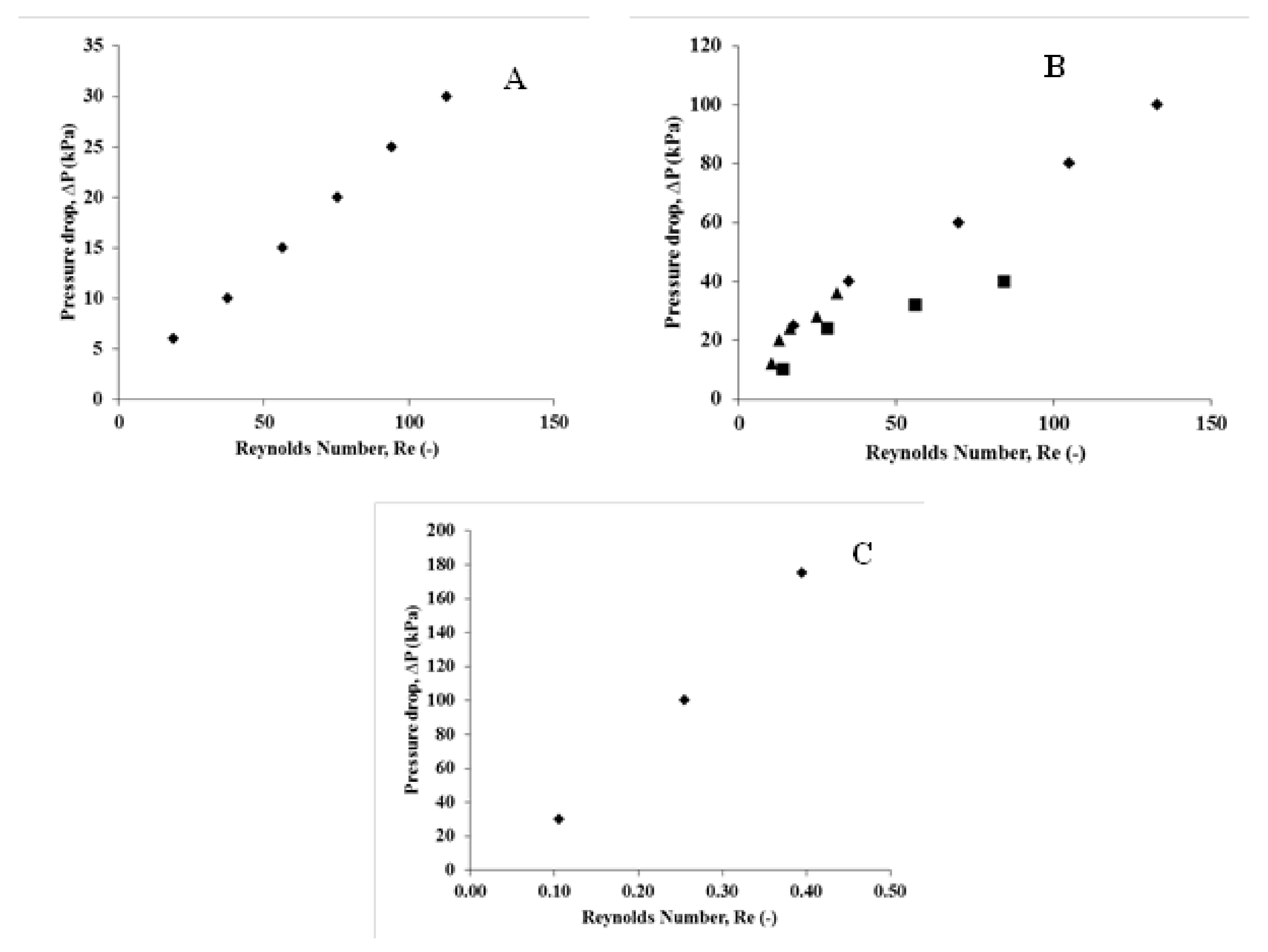
| Tsaoulidis et al. [31] | T and Y junction micro-capillaries | 0.2–0.27 | 50 | Teflon, Glass | 0.065–214.9 cm3/h | Water-ionic-liquid | Ionic liquid volume fraction | 0.1 < Re < 0.4; 30 ≤ ∆P ≤ 175 | 4 | 1 | 5, 6, 7, 8 | ; |
| Jovanovic et al. [39] | Round microcapillaries Y-mixer | 0.248, 0.498 | 1000 | Fused silica | 0.05–6 mL/min | (40%EthyleneGlycol)-water-toluene | Flow rate | 10 < Re < 150; 1000 ≤ ∆P ≤ 10000 | 4 | 1 | 17, 18, 19 | and |
| Fu [36] | Y shaped Rectangular microchannel | Hydraulic dia = 0.174 | 20 | PTFE | 4.8–62.3 mm3/h | Sulphuric acid-sodium bi-carbonate or water | Flow rate; flow velocity | 18 < Re < 114; 6 ≤ ∆P ≤ 30 | 5 | 2 | 3, 4 | |
| Kashid et al. [38] | Y shaped micro-capillary | 0.25–1 | 500 | PTFE | 5–200 mL/h | Non-reactive system: Water-cyclohexane | Flow rate; inlet velocity; slug velocity | 10 < Re < 31; 12 ≤ ∆P ≤ 36 | 1, 2, 3, 4 | 1 | 1, 2 | Pressure drop without film Pressure drop with film where |
| Salim et al. [40] | T-junction | 0.667, 0.793 | 120 | Quartz and Glass | 0 < vw < 0.55 m/s; 0 < vw < 0.325 m/s | Oil-Water | Pressure drop, Flow patterns | 30 < ∆P/L < 270 (Quartz) 30 < ∆P/L < 310 (Glass) | 4, 5, 7, 8 | 1 | 12, 13, 14 | where |
| Ladosz and von Rohr [37] | T-junction microcapillary | 0.2–0.4 | 5 | Glass silicon | 0.02–1.6 mL/min | Silicon Oil-water | Phase ratio; inlet velocity | 14 < Re < 84; 10 ≤ ∆P ≤ 40 | 4 | 1 | 9, 10, 11 | Moving film model for pressure drop |
- Two phase pressure drops involve hydrodynamic and interfacial/capillary pressure drops in microchannels
- Both experimental investigations and analytical models show that two phase pressure drop is higher than single phase pressure drop
- Modelling two phase pressure drop involves careful consideration of two aspects (a) film near the wall and (b) the movement of the film
- Two phase pressure drop depends on (i) the fluids/system under consideration (ii) volume fraction of dispersed phase (iii) material of construction of capillaries.
2.2. CFD Studies
| Authors | Channel (CH) Details | Type of Study | Parameters Varied | Output Parameters | (VMTC), 1/s | Dimensionless Number | |||||
|---|---|---|---|---|---|---|---|---|---|---|---|
| Geometry Type | CH Diameter/Size | CH Length (mm) | Flow Rate/Velocity (m/s) | Experimental /CFD | System | Flow Regime | |||||
| Kashid et al. [52] | Y type Microchannel | Dia. = 0.5–1 | 1 | 5–100 mL/h | Experimental and CFD | Water, Cyclohexane | Slug flow | Y-junction dia., Capillary diameter | Slug size | NA | NA |
| Kashid et al. [44] | T-type cross microchannel | 0.05 | 1 | Flow Velocity = 27 mm/s; 53 mm/s; 67 mm/s | CFD | Non-reactive system: Glycerol/Water (1) FC-3283/PFO (2) | Slug flow | Channel Dia., Flow Velocity, Channel Length, time, Flow velocity | Slug Length, Static Pressure, Laplace Pressure | NA | Courant Number, Capillary Number |
| Raj et al. [42] | Rectangular T-Type | 100 × 50 100 × 100 50 × 50 100 × 50 | 33 33 33 79 | Water Flow (μL/s)–0.019–0.417 Oil Flow–0.004–0.14 | CFD | Water, Oil | Slug flow | Water and Oil Flow, Channel Size, Water/oil Flow, time | Slug size | NA | Capillary Number, Reynolds Number |
| Authors | CFD Details | SOFTWARE USED | Assumptions | Findings | ||||||
|---|---|---|---|---|---|---|---|---|---|---|
| Single/Two Phase | Dimension (D) | Grid Details | VOF/ Levelset Method | Size of Microchannel | System | Steady/Unsteady | ||||
| Kashid et al. [52] | Two phase | 2D | Coarse | Free Surface Model, VOF, CSF, level set | Water-Toluene | Unsteady state | In house code (FEATFLOW) | 1, 2, 3, 4 | 1, 2, 3, 4 | |
| Kashid et al. [44] | Two phase | 2D | Mesh Size–0.5 to 2 micrometer Number of cells-58,000 | VOF | Water-Toluene | Unsteady state | Ansys Fluent Ansys GAMBIT | 1, 2, 3, 4 | 5 | |
| Raj et al. [42] | Two phase | 3D | Medium Grid (72,960 Cells) | VOF | Water-Oil | Unsteady state | Ansys Fluent | 1, 2, 3, 4 | 6, 7, 8 | |
| Yamasaki et al. [53] | Two phase | 3D | NA | VOF | 0.2 × 0.2 | Water-Octane | Unsteady state | Open source code Gerris | 1, 2, 3, 4 | |
| Azarmanesh and Farhadi, [22] | Two phase | 3D | Adaptive Mesh refinement | VOF | 0.1 × 0.1 | 984 < ρd< 1162 (kg/m3); 0.28 × 10⁻³ < μd < 68 × 10−3 kg/ms; 1240 < ρc < 4130 kg/m3; 0.73 × 10⁻³ < μc < 3.46 × 10⁻³ | Unsteady state | Fluent 6.3 | 1, 2, 3, 4 | |
| Kositanont et al. [54] | Two phase | 2D | 0.57 to 7 micron size cells; 20,040 cells | VOF | 0.0956 | Water-toluene | Unsteady state | CFX 5.6 | 1, 2, 3, 4 | |
| Lan et al. [55] | Two phase | 3D | Unstructured mesh, 0.414 million cells | Modified Levelset | 0.2 × 0.035 Inner tube; 0.4 outer tube | NA | Unsteady state | OpenFoam | 1, 2, 3, 4 | |
| Yang et al. [56] | Two phase | 2D | 32,200 cells | VOF | Main capillary width = 0.4; Length = 10.8 vertical capillary = 0.02; Length = 0.2 | Water-toluene | Unsteady state | Inhouse code | 1, 2, 3, 4 | |
| DeMenech et al. [57] | Two phase | 3D | smallest cell 5 micron | PhaseField Method | 0.1 width | Densities and viscosities considered | Unsteady state | Comsol 5.0 | 1, 2, 3, 4 | |
| Han and Chen, [58] | Two phase | 3D | 58,000 cells | Levelset Method | 0.1 width; 1 length | Water–Oil | Unsteady state | Ansys Fluent 18.1 | 1, 2, 3, 4 | |
| Sripadraja et al. [59] | Two phase | 2D | 130,000 cells | VOF | 0.1 × 0.05 | Oil-water | Unsteady state | Open source code Gerris | 1, 2, 3, 4 | |
- Inlet- Velocity value
- Wall–No slip Condition
- Outlet–Constant Pressure
2.2.1. Effect of Channel Geometry, Fluid Properties and Flowrates
2.2.2. Effect of Flow Regime
2.2.3. Effect of Channel Wettability
3. Influence of Flow Patterns on Transport Property
3.1. Experimental Studies
3.1.1. Effect of Geometric, Operating Parameters, Wallfilms and Fluid Properties on VMTC
3.1.2. Comparison of VMTC’s of Microchannels and Conventional Equipments
3.1.3. Evaluation of VMTC’s for Systems Involving IL’s, DES as Solvents
| Authors | Channel Details | Type of Study | ||||||||||
|---|---|---|---|---|---|---|---|---|---|---|---|---|
| Geometry Type | Channel Diameter | Channel Length (mm) | Channel Material | Flow Rate/Velocity | Experimental/CFD | System | Flow Regime | Parameters Varied | Assumptions | Limitations/Opportunities | Findings | |
| Kashid et al. [1] | Micro-capillary, Y-Type | 0.5, 0.75, 1 | 100–1000 | Polytetraflouroethylene (PTFE) for channel and flow splitters, steel for outlet channel in flow splitter | 5–60 mL/h | Experimental | Non-reacting system Water-iodine-kerosene; Kerosene-acetic acid-water; Water-succinic acid-n-butanol | Slug flow | Capillary diameter, slug velocity, flow ratio of aqueous and organic phases | 1, 2 | 1 | 1, 2, 3, 4, 5 |
| Zhao et al. [16] | Rectangular micro-channel, T-type | 0.4 × 0.6; 0.6 × 0.6 | Stainless steel | 0.01–2.5 m/s; 0.005–2 m/s | Experimental | Water-succinic acid-n-butanol | NA | Type of flow: opposed and cross flow; height of channel; velocity of fluids | 3 | 1 | 6, 7, 8 | |
| Dessimoz et al. [9] | Rectangular micro-channel, Y-Type and T-type | 0.25 × 0.292 for Y type; 0.4 × 0.4 for T-type | 40 for Y type and 56 for T type | Glass | Experimental | Reacting system, Hexane-trichloroacetic acid-water + NaOH; Toluene-trichloroacetic acid-water + NaOH | Slug flow and parallel flow | Linear velocity of fluids, initial concentration of water | 4, 5 | 1, 2 | 9, 10 | |
| Ghaini et al. [66] | Micro-capillary, Y-Type | 0.5, 0.75, 1 | 100–1000 | Poly-tetraflouro-ethylene (PTFE) for channel and flow splitters, steel for outlet channel in flow splitter | 30–80 mL/h | Experimental | Non-reacting system, Water-iodine-kerosene; Kerosene-acetic acid-water; Water-succinic acid-n-butanol | Slug flow | Capillary diameter, slug velocity, flow ratio of aqueous and organic phases | 3, 4, 5 | 1, 2 | 11, 12 |
| Assmann & von Rohr, [67] | Micro-capillary | 0.22 | 1350 | Polydimethylsiloxane | Overall flowrate: 0.26 mL/min | Experimental | Non-reactive system: Water-Vanillin-toluene with Nitrogen as carrier gas | Segmented/ Slug flow without carrier gas | VMTC, extraction efficiency, velocity profiles | 3, 5 | 1, 2 | 13, 14 |
| Tang et al. [81] | Vertical flow microchannel | 0.8; 1.2 | 236 | Glass | 0.237–0.373 mL/min based on total velocity | Experimental | Water-succinic acid-n-butanol | Droplet flow | Flow rate, total flow velocity | 3, 4, 5 | 1, 2 | 11, 12 |
| Tsaoulidis et al. [82] | T-junction microchannel | 0.5 | 100–300 | Polymethyl-metacrylate (PMMA) | Experimental | Non-reactive system: Nitric acid-U(IV)-Ionic liquid | Slug flow | pH, residence time, channel width, flow velocity, phase flow ratio | 3, 5 | 1 | 16 | |
| Xu et al. [69] | Micro-capillary, T-type | 0.6, 0.8, 1 | 500, 1000, 1500, 2000, 2500 | Teflon | 5–100 mL/h | Experimental | Reacting system: Sodium hydroxide-nbutyl acetate (Alkaline hydrolysis reaction: Mass transfer with fast chemical reaction) | Slug flow | slug velocity, channel length | 3, 5 | 4, 5 | 8, 17, 18, 19 |
| Di Miceli Raimondi et al. [70] | Square microchannel | 0.21 × 0.21; 0.3 × 0.3 | 350–1640 | Silicon and glass | 2.5–30 mL/h | Experimental | Non-reacting system: Water-acetone-toluene | Slug flow | droplet velocity, droplet volume | 3, 5 | 6 | 20, 21 |
| Singh et al. [76] | T-junction microchannel Serpentine microchannel Split and recombine microchannel | Equivalent diameter: 0.278, 0.319 | Poly Ether Ether Ketone (PEEK); FRX200, from Syrris Pvt Ltd. | 0.01–10 mL/min | Experimental | Water-succinic acid-n-butanol | Parallel and slug flow | Phase ratio, residence time, flow velocity | 3, 5 | 1, 2 | 26 | |
| Arsenjuk et al. [71] | Micro-capillary | 0.8 | 300 | Flourinated ethylene propylene and glass | 8 mm/s; 25 mm/s; 40 mm/s | Experimental | Non-reactive system: Water-glycerol-kerosene | Slug flow | average velocity | 3, 5 | 7 | 27 |
| Bai et al. [10] | T-junction and crossing junction microchannels | 0.3 × 0.5 | 650 | Polymethyl-metacrylate | 0.005–0.02 mL/min | Experimental | Non-reactive system: Water-Rhodamin 6G-Ionic Liquid | Slug flow | Flow rate, time | 3, 5 | 8 | 8, 28 |
| Li & Angeli, [72] | T-junction micro-capillary | 0.2–0.5 | 50–250 | Quartz | 0.653–21.205 mL/min | Experimental | Non-reactive System: Nitric acid-Eu(III)-Ionic liquid | Slug flow | Time, mixture velocity | 3, 5 | 1, 2 | 8 |
| Matsuoka et al. [73] | Circular channel | 0.6–2 of channel and inlet diameters of 2 and 2.4 | 100–1200 | Stainless steel | 0.5–8 mL/min | Experimental | Non-reactive system: Water-phenol-dodecane | Slug flow | Reynolds number, Residence time | 3, 5 | 9 | 8, 30 |
| Sahu et al. [77] | Y-junction Serpentine square microchannels | 0.15 × 0.15 | 56, 266 | PTFE | 0.04–0.1 | Experimental | Non-reactive system: Water-propionic acid-toluene | Parallel and slug flow | Phase ratio, residence time, flow velocity | 3, 5 | 2 | 31, 32 |
| Ani et al. [83] | Circular channel | 1.22 mm diameter | 100–300 | Glass | Experimental | Non-reactive system: Liquid fuel-dibenzothiophene-DES solvent | Slug flow, Intermittent flow, Annular flow | Mixture velocity, DES volume fraction, channel length | 3, 5 | 8 | 8, 28 | |
| Cao et al. [15] | Rectangular microchannels | Hydraulic dia.: 0.2, 0.4, 0.6 | 105 | Glass | 0.2–150 mm/s | Experimental | Water-butanol; Water-toluene; Water-hexane | All flow patterns described | flow velocity, channel width | 3, 5 | 1, 10, 11 | 8, 33 |
| Sattari-Najafabadi and Esfahany, [75] | Circular microchannel | 0.6 | PTFE | 0.083–0.217 mL/min | Experimental | Reactive system: Water (with NaOH)-trichloroacetic acid-nhexane in presence of sodium dodecyl sulfate | Slug flow | Flow rate | 3, 5 | 1 | 35, 36, 37 | |
| Sattari-Najafabadi et al. [74] | Square and rectangular microchannel with 3 different junctions (cross and Tshape) | 0.4 × 0.4 0.3 × 0.6 | 120 | Borosilicate glass | 0.1–0.55 mL/min | Experimental | Fast Reactive system: Water (with NaOH)-acetic acid-n-hexane | Slug flow | Flow rate | 3, 5 | 1 | 8, 38, 39 |
| He et al., [78] | Rectangular Yjunction serpentile channels | 0.3–1 | 125 | Stainless steel | 0.02–0.15 m/s | Experimental | Non-reactive system: Pr/Nd from chloride solution 2-ethyl-hexyl phosphoric acid ester | Slug flow | pH, residence time, channel width, flow velocity | 3, 5 | 1, 2 | 40, 41 |
| Jiang et al. [79] | Rectangular microchannels for serpentine micro-reactors | 0.5 | 125 | Polymethyl-metacrylate | 0.56–3 mm3/s | Experimental | Non-reactive system: La/Ce from chloride solution 2-ethyl-hexyl phosphoric acid ester | Slug flow | Residence time, channel width, flow velocity | 3, 5 | 1, 2 | 40, 41 |
| He et al. [84] | T-junction microreactor | 1.5–6.5 | 1000 | Stainless steel | 0.1–1 mL/min | Experimental | Non-reactive system: Hydrochloric acid-smarium-2- ethylhexyl phosphonic acid mono-2-ethylhexyl (EHEHPA or P507) | NA | Channel width, pH, channel length | 3, 5 | 1, 12 | 42, 43, 44 |
| Sen et al. [80] | Serpentile microchannel with microbore | 0.75 | 7300 | 0.01–10 mL/min | Experimental | Non-reactive system: Tributyl phosphate in Dodecane-Uranium | Annular and droplet flow | Phase ratio, residence time, flow velocity | 3, 5 | 1, 2 | 45 | |
| Wu et al., [11] | T-junction, crossjunction straight microchannels | 0.2–0.6 | 50 | Glass | 4–90 mL/h | Experimental | Non-reactivev systems: Water-Silicon Oil; Water-toluene; water-1butanol; n-hexane; mineral oil | Tubing, dripping, jetting flow | flow velocity; flow rate | 3, 5 | 10 | 33 |
| Zhang et al. [12] | Microcapillary | 0.8–1.8 | 200 | PTFE | Experimental | Toluene-water; Toluene-sulfuric-acid; Ethylacetate-water | Tubing, dripping, jetting flow | Channel Diameter Temperature | 3, 5 | 1, 2 | 33, 46 | |
| Yao et al. [85] | Meandering microchannel | 0.3 × 0.6 | 440 | Glass | 0.1–0.9 mL/min | Experimental | water (with NaOH)-acetic acid-toluene; | Slug flow | Flow rate, effect of continuous and dispersed phase using glycerol and silicon oil content variation | 3, 5 | 12 | 8, 47 |
3.1.4. Comprehensive Regime Map for LL Systems Having Transferable Component
3.2. CFD Studies of Influence of Flow Patterns on Transport Property
| Authors | Channel Details | Type of Study | Parameters Varied | Output Parameters | VMTC, 1/s | Dimensionless Number and Range | |||||
|---|---|---|---|---|---|---|---|---|---|---|---|
| Geometry Type | Channel Diameter | Channel Length (mm) | Flow Rate/Velocity | Experimental/CFD | System | Flow Regime | |||||
| Kashid et al. [65] | Micro-channel | 0.5 × 0.5 | 2 | 3 mm/s to 16 mm/s | CFD simulation | Reactive system: Kerosene-acetic acid-water; Non-reactive system: Water-succinic acid-nbutanol | Slug flow | time, flow speed, slug length | Flow patterns, VMTC, concentration profiles | 0.12–0.2 s−1 | NA |
| Gómez-Pastora et al. [88] | Y-microchannels | 0.2; 0.04; 0.16 | 2 | 1 mm/s to 20.1 mm/s | Experimental and CFD | Flourescin sodium salt in water-deionized water | Stratified flow | Inlet velocity; width to height ratio, phase ratio | Seperation factor, flow patterns | NA | Low Reynolds number |
| Di Miceli Raimondi et al. [89] | Square micro-channel | 0.06–0.96 | 100 | CFD simulation | Non-reactive system: Water-nbutanol | Slug flow | Reynolds number, residence time | VMTC, concentration profiles | 0.05–10 s−1 | Capillary number, Reynolds number | |
| Cito et al. [90] | Rectangular micro-channel | <1 | 10 | CFD simulation | Fluid with SC = 1000, water | Slug flow | Time | Flow patterns, Sherwood number, wall mass transfer rate | Reynolds number, 1–500; Sherwood number | ||
| Tsaoulidis and Angeli [82] | Micro-capillary | 0.5–2 | 10,000–31,500 mm | 0.117–5.67 mL/min | Experimental and Numerical | Nitric acid-UO2-TBP (IL) | Slug flow | Residence time, mixture velocity, | Extraction efficiency, VMTC | 0.049–0.29 s−1 | |
| Zhang et al. [86] | Circular capillary | 0.6 | 2.22 | CFD simulation | Reactive system: Water (NaOH)-aceticacid-nbutanol | Slug flow | Time, vertical distance | Enhancement factor, concentration profiles, flow patterns, VMTC, velocity profiles | 0.1–0.3 s−1 | Hatta number (0.32) | |
| Ramji and Puspavanam, [91] | Rectangular microchannel | NA | NA | NA | CFD simulation | Viscosity ratio, density ratio, diffusivity ratios; water-acetone-toluene system for model validation with experiments in literature | Slug flow | Viscosity ratio; Reynolds number; slug holdup | Flow patterns, velocity, concentration profiles | NA | Reynolds number, 1–100, Peclet number 1–5000 |
| Authors | CFD Details | Software Used | Assumptions | Limitations | Findings | |||||
|---|---|---|---|---|---|---|---|---|---|---|
| Single/Two Phase | Dimension (D) | Grid Details | VOF/Leve-Set Method | with/without Mass Transfer | Steady/Unsteady State | |||||
| Kashid et al. [65] | Two phase | 2D | 640 × 128 elements | NA | with mass transfer with model of Yang and Mao [92] | Unsteady state governing equations with convection-diffusion equations | FEATFLOW open source software | 1, 2, 3, 4, 5 | 1, 2, 3 | 1, 2 |
| Cito et al. [90] | Two phase | 2D | 125 × 100 | Level-Set method | with mass transfer with model of Yang and Mao [92] | Unsteady state governing equations with convection-diffusion equations | JADIM code | 1, 3 | 4 | 3, 4 |
| Di Miceli Raimondi et al. [89] | Two phase | 2D | 47,187 | NA | with mass transfer | Unsteady state governing equations with convection-diffusion equations | Fluent commercial software | 1, 3 | 1, 5 | 5, 6, 7, 8 |
| Tsaoulidis and Angeli [82] | Two phase | 2D axisymmetric | Individual cell size is 32 μm time step 0.05 s | None | with mass transfer | Continuity, momentum, species transport equations for reactions, Realizable k-ε for turbulence | 1, 4, 5 | 1, 6, 7 | 9 | |
| Zhang et al. [86] | Two phase | 2D | Each grid cell of size 10 μm and fine near the boundaries 2 μm | NA | with mass transfer, both boundary conditions (flux continuity and thermodynamic equilibrium) | Unsteady state governing equations with convection-diffusion equations for both phases | Ansys Fluent | 1 | 1 | 10, 11, 12 |
| Gómez-Pastora et al. [88] | Two phase | 2D | 400 × 100 | VOF | Mass transfer only due to concentration gradient | Unsteady state governing equations with convection-diffusion equations | FLOW 3D commercial software | 1 | 1 | 13, 14, 15 |
| Ramji and Puspavanam, [91] | Two phase | 2D | 202 × 101 | NA | Dimensionless Transient Mass transfer | Dimensionless Unsteady state governing equations with convection-diffusion equations | In-house code for solving dimensionless governing equations and interface movement | 1, 4, 5, 6, 7 | 1 | 16, 17 |
- Axial and radial velocities of the walls are equal to slug/plug velocity
- No slip boundary condition at channel wall
- Equal stresses at the interfaces between two phases
- Flux continuity boundary condition at the interface
- Zero flux set at the channel wall
- Periodic boundary condition to satisfy flux continuity at the interface.
4. Influence of Flow Patterns on Transport Property: Heat Transfer
4.1. Experimental Studies of Heat Transfer in Microchannels Involving Liquid-Liquid Two Phase Flow
4.2. CFD Studies of Heat Transfer in Microchannels Involving Liquid-Liquid Two Phase Flow
4.3. Other Aspects: Film Thickness, Peclet Number Effect, Systems Considered, Scope for Different Geometries
| Authors | Correlation |
|---|---|
| Dai et al. [100] | |
| Giolla Eain et al. [99] |
5. Conclusions
- Flow patterns namely parallel, slug, annular, annular-slug, slug-dispersed have been reported by authors but some new patterns like rivulet and serpentine patterns have also been observed for liquid-liquid systems in main channels of microchannels
- Flow patterns in junctions (cross or T-junctions) are also summarized as tubing, dripping and jetting. Several works are available but a connection between the flow patterns in the junctions and the main channels needs to be made while creation of regime maps
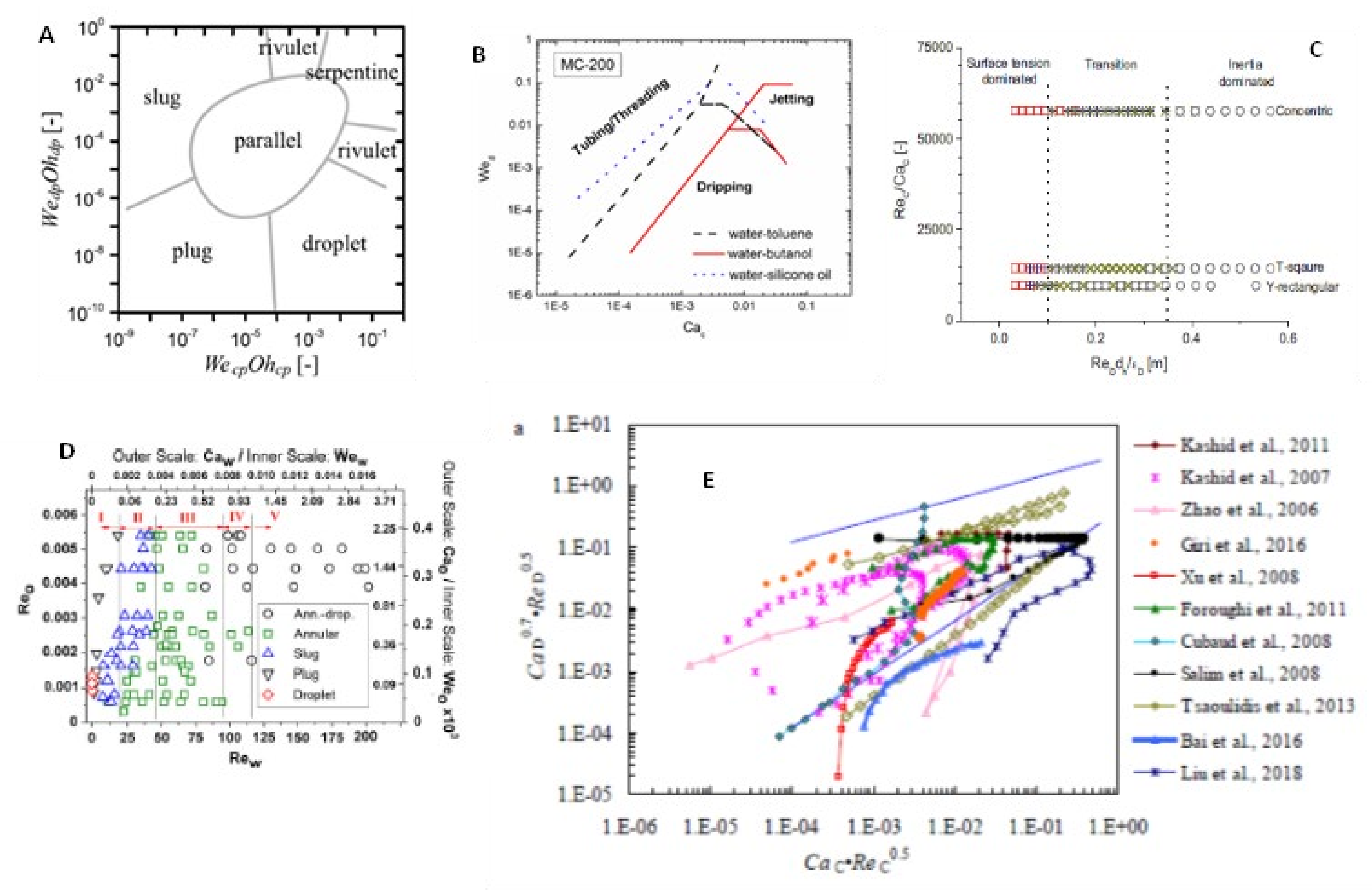
- Regime maps have been presented by authors with dimensionless numbers like product of Reynolds numbers and Capillary numbers or product of Weber and Ohnesorge numbers. However, there is no consensus on the particular regime maps and no regime map is able to predict the works of the entire literature correctly
- Pressure drop studies are in the form of experimental investigations and analytical models. The pressure drop models are seen to predict well with the experimental data for similar viscosity systems
- Few CFD models focusing on flow patterns have been found for liquid-liquid systems. The models have shown good predictive capabilities with experimental results. However, Capillary number plays an important role in the predictions. For certain Capillary numbers the CFD models have been unable to predict the flow patterns as those of experimental observations suggesting more amount of research works to be carried out in this area.
- Mass transfer studies in experimentation have shown the effect of operating variables and properties and geometric dimensions. VMTC is found to increase with an increase in flow velocity, presence of inerts, presence of surfactants, increase in flow ratio. VMTC however decreases with increase in characteristic channel dimension (like channel width or diameter) for specific channel length.
- For cases of extraction of rare earths or uranium, the residence times are found to be less than 20 s which is an order of magnitude less than conventional batch or continuous processes
- The VMTC’s for test systems involving conventional solvents or systems involving IL’s or DES’s are two orders of magnitude higher than the VMTC’s of conventional equipment’s. However, commercialization needs stacking up of a number of microchannels in series and hence needs substantial research in this direction
- For reactive systems, the measured MTC’s are two to three times the ones predicted by film theory due to the enhancement in mass transfer during reaction
- CFD studies have been carried out majorly with stationary interfaces with specified slug lengths obtained from experimental measurements. Boundary conditions for the interface are also specified from experimental measurements. In contrast, coupled system of equations involving interface capturing methods, pressure-velocity and concentration equations need to be solved.
- All investigations in heat transfer studies have shown higher heat transfer rates from 180% to 700% as compared to single phase flow. It is important to note that lower sizes (~0.1 mm) give lower percentage increase in heat transfer rate (180%) while higher sizes (~2 mm) give higher percentage increase in heat transfer rate.
- Most CFD studies have been carried out in 2D or 2D axisymmetric mode while CFD simulations need to carried out in 3 dimensions to get better insight of qualitative and quantitative results.
6. Future Scope
- Several works have been focused on understanding the flow patterns. Few researchers have focussed on flow patterns at the junctions while many of them have focused on the main channels only. In main channels, few researchers observed new flow patterns which are different than the obvious flow patterns of parallel, slug, annular and dispersed flow or a combination of these. These patterns need to be studied more extensively by research fraternity similar to the work of researchers Yagodnitsyna et al. [7], needs to be taken up by more researchers. Numerical simulations for these cases needs to be carried out which for two phase flows for various systems with different fluid properties and operating parameters and such models need to be validated with the rich experimental data available in the literature both in junctions and main channels
- Commercial applications need to be found where LLE can be carried out in micro-channels. The regime in which such operations would be carried out will pave the way for efficient equipment design. Presently, from the reviewed literature, extraction of rare earth metals seems to be the most promising application that can be commercialized in micro-channels.
- There have been very extensive and comprehensive studies for predictions of regime maps by some researchers. A few researchers, claim universal regime maps. However, the individual investigations in literature (for reactive and non-reactive systems) for micro-channels does not quite comply with the flow regime maps except the regime map by Zhang et al. [12]. This might be due to the use of different material of constructions for experimental investigations. Further, several authors claim combination of different dimensional numbers. One of the recommendations would be to form a consortium of experts for development of comprehensive regime maps which can be used for any system which currently seems to be a challenge. Numerical simulations with the power of volume capturing methods would play a vital role in preparing such universal maps
- Surprisingly, most of the experimental works compare the VMTC’s in micro-channels with conventional equipment’s and the VMTCs are two orders of magnitude higher than ones in conventional extractors. But inspite of such various advantages of microchannels, commercial application of micro-channels are not reported in literature. Gaps in commercialization of micro-channel extraction units need to be found and research work needs to be taken up in that direction
- The advantages of CFD simulations in understanding flow patterns and mass transfer in micro-channels have not be harnessed to its full potential. More number of works of CFD with green solvents like ionic-liquids and Deep Eutetic Solvents (DES) need to be taken up and validated against the experimental results both in terms of hydrodynamics and mass transfer
- Mass transfer models need to be used for predictions for VMTC’s with micro-channels as well for the various systems that have been discussed in the present article (both experimental and two phase CFD simulations). Surprisingly, mass transfer models have not been used extensively for predictions of interfacial area and VMTC’s. Softwares like Ansys Fluent/Comsol/in-house-code have been used by authors who have developed CFD models. The surface is however considered constant in most of the cases. Movement of the surface is important to capture the Marangoni instabilities which enhances mass transfer.
- Very few works in terms of coupled equations of front tracking methods (Level-Set/VOF) with mass transfer models with Navier-Stokes equations exist in the literature for drops or bubbles moving in continuous liquids or liquid films on solid surfaces. However, in these models the distribution coefficient is used as a transformation parameter and thus assumed to be constant. However, in reality, the distribution coefficient depends on state variables and suffers significant changes. Hence, robust mass transfer models also needs to be developed before they can be applied to microchannels for prediction of VMTC’s and interfacial areas. Ideally, a comprehensive mathematical model taking account of the interface deformation, interfacial concentration jump and variable distribution coefficient needs to be developed.
- More test systems need to be studied for understanding heat tranfer rates in liquid-liquid systems with a wide range of sizes
- Higher range of Re numbers need to be considered (100 < Re < 1000) for understanding the effect of various parameters on heat transfer rates.
Author Contributions
Funding
Institutional Review Board Statement
Informed Consent Statement
Data Availability Statement
Conflicts of Interest
Abbreviations
| CFD | Computational Fluid Dynamics |
| CMC | Critical Micelle Concentration |
| Ca | Capillary number |
| DES | Deep Eutetic Solvents |
| IL | Ionic liquid |
| LLE | Liquid-Liquid Extraction |
| LS | Level set |
| MAC | Marker and Cell |
| MTC | Mass transfer coefficient |
| Nu | Nusselt number |
| Oh | Ohnesourge number |
| Re | Reynolds number |
| Sc | Schmidt number |
| SDS | Sodium dodecyl sulphate |
| Sh | Sherwood number |
| VOF | Volume of Fluid |
| We | Weber number |
| Notations | |
| Area of droplet, m2 | |
| a, b, c, d | Constants used in correlation of [16], Table 7 |
| B | Constant, (-) |
| C3 | Constant, (-) |
| C4 | Constant, (-) |
| transformed concentration of a species in equation 8, kg m−3 | |
| transformed concentration of a species in equation 9, kg m−3 | |
| concentration of species of jth component in equation, kg m−3 | |
| concentration of continuous phase, kg m−3 | |
| concentration of dispersed phase, kg m−3 | |
| concentration of liquid phase, kg m−3 | |
| concentration of gas phase, kg m−3 | |
| Ca | Capillary number, - |
| Two phase Capillary number, - | |
| Mean Capillary number of two phase, - | |
| Dispersed phase Capillary number | |
| concentration of Sodium dodecyl sulphate, kg m−3 | |
| Diameter, m | |
| transformed diffusivity, m2 s−1 | |
| hydraulic diameter, m | |
| hydraulic diameter, m | |
| Dispersed phase | |
| Hydraulic diameter, m | |
| liquid diffusivity, m2 s−1 | |
| Diffusivity of component 1, m2 s−1 | |
| Diffusivity of component 2, m2 s−1 | |
| Diffusivity of the jth component, m2 s−1 | |
| Gas diffusivity, m2 s−1 | |
| Liquid diffusivity, m2 s−1 | |
| Effective diffusivity, m2 s−1 | |
| Continuous phase diffusivity, m2 s−1 | |
| Dispersed phase diffusivity, m2 s−1 | |
| Droplet diameter, m | |
| Distribution coefficient, - | |
| Thickness of the film, m | |
| Fourier number, - | |
| Function for volume of fluid approach | |
| H | Channel depth, m |
| H1 | Channel depth for microchannel as depicted in Figure 15, m |
| H2 | Channel depth for microchannel as depicted in Figure 15, m |
| Distribution coefficient of jth component | |
| Regularized Heaviside function, - | |
| Mass transfer coefficient, m s−1 | |
| Overall/volumetric Mass Transfer coefficient (VMTC), s−1 | |
| Combined MTC, m s−1 | |
| Film MTCs, m s−1 | |
| k | Ratio of radius used in pressure drop correlation, Table 2 |
| Length of droplet, m | |
| Dimensionless droplet length, - | |
| Droplet length, m | |
| Slug length, m | |
| Dimensionless slug length, - | |
| Length of unit slug used in pressure drop correlation, m | |
| Unit cell length, m | |
| Length of the channel, m | |
| m | Constant in Table 7, - |
| m | Heat capacity ratio in Table 8, - |
| Unit normal to the interface, - | |
| Transformed unit normal to the interface, - | |
| Unit cell pressure drop, kg s−1 | |
| Volumetric flow rate ratio,– | |
| Reynolds number, - | |
| Dispersed phase Reynolds number | |
| Mean Reynolds number, - | |
| R | Radius, m |
| Continuous phase Sherwood number, - | |
| Continuous phase Schmidt number, - | |
| Sc | Schmidt number, - |
| T | Temperature, K |
| T | Time, s |
| Transformed time, s | |
| Velocity, m s−1 | |
| Transformed velocity, m s−1 | |
| Bubble velocity, m s−1 | |
| Dispersed phase velocity | |
| Slug velocity, m s−1 | |
| Gas phase velocity | |
| Liquid phase velocity | |
| V | Velocity, m s−1 |
| Dispersed phase velocity | |
| Inlet velocity, m s−1 | |
| Outlet velocity, m s−1 | |
| Droplet width, m | |
| W, w | Channel Width, m |
| Subscripts | |
| 1 | continuous phase |
| 2 | Dispersed phase |
| continuous phase | |
| Dispersed phase | |
| Dispersed phase or droplet | |
| Effective | |
| FD | Film to droplet |
| FS | Film to slug |
| Gas | |
| Inlet | |
| Component | |
| Liquid | |
| MTC | |
| Mean | |
| Oil | Oil |
| Outlet | |
| Residence time | |
| Slug | |
| Saturated | |
| Velocity | |
| Two phase | |
| UC | Unit cell |
| W | Wall |
| water | Water |
| Greek Symbols | |
| Water phase fraction, - | |
| Dispersed phase fraction, - | |
| Film thickness, m | |
| Interface thickness in level-set equation, - | |
| Constant in pressure drop equation | |
| Level-set function | |
| Constant for correlation in Table 7, - | |
| Viscosity of the continuous phase | |
| Viscosity of the dispersed phase | |
| η | Variable in pressure drop equation |
| Density | |
| Surface tension | |
| Gas phase hold up in Table 7, - | |
| Contact time of aqueous and organic phases in micro-channel | |
References
- Kashid, M.N.; Harshe, Y.M.; Agar, D.W. Liquid−liquid slug flow in a capillary: An alternative to suspended drop or film contactors. Ind. Eng. Chem. Res. 2007, 46, 8420–8430. [Google Scholar] [CrossRef]
- Cademartori, S.; Cravero, C.; Martini, M.; Marsano, D. CFD Simulation of the Slot Jet Impingement Heat Transfer Process and application to a temperature control system for galvanizing line of metal band. Appl. Sci. 2021, 11, 1149. [Google Scholar] [CrossRef]
- Cravero, C.; Domenico, D.; Leutcha, P.J.; Marsano, D. Strategies for the Numerical Modeling of Regenerative Preheating systems for recycled glass raw material. Math. Model. Eng. Probl. 2019, 6, 324–332. [Google Scholar] [CrossRef] [Green Version]
- Dixit, T.; Ghosh, I. Review of micro-and mini-channel heat sinks and heat exchangers for single phase fluids. Renew. Sustain. Energy Rev. 2015, 41, 1298–1311. [Google Scholar] [CrossRef]
- Al-Azzawi, M.; Mjalli, F.S.; Husain, A.; Al-Dahhan, M. A Review on the hydrodynamics of the Liquid–Liquid two-phase flow in the microchannels. Ind. Eng. Chem. Res. 2021, 60, 5049–5075. [Google Scholar] [CrossRef]
- Kashid, M.N.; Renken, A.; KiwiMinsker, L. Gas–liquid and liquid–liquid mass transfer in microstructured reactors. Chem. Eng. Sci. 2011, 66, 3876–3897. [Google Scholar] [CrossRef]
- Yagodnitsyna, A.A.; Kovalev, A.V.; Bilsky, A.V. Flow patterns of immiscible liquid-liquid flow in a rectangular microchannel with T-junction. Chem. Eng. J. 2016, 303, 547–554. [Google Scholar] [CrossRef]
- Kovalev, A.V.; Yagodnitsyna, A.A.; Bilsky, A.V. Flow hydrodynamics of immiscible liquids with low viscosity ratio in a rectangular microchannel with T-junction. Chem. Eng. J. 2018, 352, 120–132. [Google Scholar] [CrossRef]
- Dessimoz, A.L.; Cavin, L.; Renken, A.; Kiwi-Minsker, L. Liquid–liquid two-phase flow patterns and mass transfer characteristics in rectangular glass microreactors. Chem. Eng. Sci. 2008, 63, 4035–4044. [Google Scholar] [CrossRef] [Green Version]
- Bai, L.; Zhao, S.; Fu, Y.; Cheng, Y. Experimental study of mass transfer in water/ionic liquid microdroplet systems using micro-LIF technique. Chem. Eng. J. 2016, 298, 281–290. [Google Scholar] [CrossRef]
- Wu, Z.; Cao, Z.; Sunden, B. Flow patterns and slug scaling of liquid-liquid flow in square microchannels. Int. J. Mult. Flow. 2019, 112, 27–39. [Google Scholar] [CrossRef]
- Zhang, Q.; Liu, H.; Zhao, S.; Yao, C.; Chen, G. Hydrodynamics and mass transfer characteristics of liquid–liquid slug flow in microchannels: The effects of temperature, fluid properties and channel size. Chem. Eng. J. 2019, 358, 794–805. [Google Scholar] [CrossRef]
- Kashid, M.N.; Gerlach, I.; Goetz, S.; Franzke, J.; Acker, J.F.; Platte, F.; Agar, D.W.; Turek, S. Internal circulation within the liquid slugs of liquid-liquid slug flow capillary micro-reactor. Ind. Eng. Chem. Res. 2005, 44, 5003–5010. [Google Scholar] [CrossRef]
- Kashid, M.N.; Rivas, D.F.; Agar, D.W.; Turek, S. On the hydrodynamics of liquid–liquid slug flow capillary microreactors. Asia-Pac. J. Chem. Eng. 2008, 3, 151–160. [Google Scholar] [CrossRef]
- Cao, Z.; Wu, Z.; Sattari-Najafabadi, M.; Sunden, B. Liquid-liquid flow patterns in micro-channels. In Heat Transfer Summer Conference; American Society of Mechanical Engineers: Bellevue, WA, USA, 2017. [Google Scholar]
- Zhao, Y.; Chen, G.; Yuan, Q. Liquid–liquid two-phase mass transfer in the T-junction microchannels. AlChE J. 2007, 53, 3042–3053. [Google Scholar] [CrossRef]
- Cubaud, T.; Mason, T.G. Capillary threads and viscous droplets in square microchannels. Phys. Fluids 2008, 20, 053302. [Google Scholar] [CrossRef] [Green Version]
- Fu, T.; Wu, Y.; Ma, Y.; Li, H.Z. Droplet formation and breakup dynamics in microfluidic flow-focusing devices: From dripping to jetting. Chem. Eng. Sci. 2012, 84, 207–217. [Google Scholar] [CrossRef]
- Carrier, O.; Funfschilling, D.; Li, H.Z. Effect of the fluid injection configuration on droplet size in a microfluidic T junction. Phys. Rev. E 2014, 89, 013003. [Google Scholar] [CrossRef]
- Du, W.; Fu, T.; Ma, Y.; Li, H.Z. Breakup dynamics for high-viscosity droplet formation in a flow-focusing device: Symmetrical and asymmetrical ruptures. AlChE J. 2016, 62, 325–337. [Google Scholar] [CrossRef]
- Van Loo, S.; Soukatch, S.; Gilet, T. Droplet formation by squeezing in a microfluidic cross-junction. Microfluid. Nanofluidics 2016, 20, 146. [Google Scholar] [CrossRef]
- Foroughi, H.; Kawaji, M. Viscous oil–water flows in a microchannel initially saturated with oil: Flow patterns and pressure drop characteristics. J. Multiph. Flow 2011, 37, 1147–1155. [Google Scholar] [CrossRef]
- Azarmanesh, M.; Farhadi, M. The effect of weak-inertia on droplet formation phenomena in T-junction microchannel. Meccanica 2016, 51, 819–834. [Google Scholar] [CrossRef]
- Svensson, A.; Wu, Z.; Sunden, B. Effects of size and sodium dodecyl sulfate on mass transfer for liquid-liquid two-phase flow in non-circular glass microchannels. In International Conference on Nanochannels, Microchannels, and Minichannels; American Societyof Mechanical Engineers: Vienna, Austria, 2018; p. V001T01A001. [Google Scholar]
- Kashid, M.N.; Renken, A.; Kiwi-Minsker, L. CFD modelling of liquid–liquid multiphase microstructured reactor: Slug flow generation. Chem. Eng. Res. Des. 2010, 88, 362–368. [Google Scholar] [CrossRef] [Green Version]
- Kashid, M.; Kiwi-Minsker, L. Quantitative prediction of flow patterns in liquid–liquid flow in micro-capillaries. Chem. Eng. Process. Process Intensifi. 2011, 50, 972–978. [Google Scholar] [CrossRef]
- Tsaoulidis, D.; Dore, V.; Angeli, P.; Plechkova, N.V.; Seddon, K.R. Flow patterns and pressure drop of ionic liquid–water two-phase flows in microchannels. Int. J. Mult. Flow 2013, 54, 1–10. [Google Scholar] [CrossRef] [Green Version]
- Sugiura, S.; Nakajima, M.; Oda, T.; Seki, M. Effect of interfacial tension on the dynamic behavior of droplet formation during microchannel emulsification. J. Colloid. Interface Sci. 2004, 269, 178–185. [Google Scholar] [CrossRef]
- Yagodnitsyna, A.A.; Kovalev, A.V.; Bilsky, A.V. Experimental study of ionic liquid-water flow in T-shaped microchannels with different aspect ratios. In Journal of Physics: Conference Series; IOP Publishing: Mexican City, Mexico, 2017; p. 032026. [Google Scholar]
- Yagodnitsyna, A.; Kovalev, A.; Bilsky, A. Experimental investigation of immiscible liquids flow in a T-shaped microchannel. In Proceedings of the 10th Pacific Symposium on Flow Visualization and Image Processing, Naples, Italy, 15–18 June 2015; pp. 1–10. [Google Scholar]
- Su, Y.; Chen, G.; Yuan, Q. Effect of viscosity on the hydrodynamics of liquid processes in microchannels. Chem. Eng. Technol. 2014, 37, 427–434. [Google Scholar] [CrossRef]
- Garstecki, P.; Fuertsman, M.J.; Stone, H.A.; Whitesides, G.M. Formation of droplets and bubbles in a microfluidic T-junction—scaling and mechanism of break-up. Lab Chip 2006, 6, 437–446. [Google Scholar] [CrossRef]
- Vansteene, A.; Jasmin, J.; Cavadias, S.; Clarisse, M.; Cote, G. Towards chip prototyping: A model for droplet formation at both T and X junctions in dripping regime. Microfluid. Nanofluidics 2018, 22, 1–14. [Google Scholar] [CrossRef]
- Li, Y.; Wang, J.; Li, D.; Liu, R. Flow pattern diagrams of oil-water two-phase microflows and stable parallel flows obtained at low Reynolds numbers. Int. J. Multiph. Flow 2018, 98, 139–146. [Google Scholar] [CrossRef]
- Li, M.; Liu, Z.; Pang, Y.; Yan, C.; Wang, J.; Zhao, S.; Zhou, Q. Flow topology and its transformation inside droplets traveling in rectangular microchannels. Phys. Fluids 2020, 32, 052009. [Google Scholar]
- Liu, Z.; Li, M.; Pang, Y.; Zhang, L.; Ren, Y.; Wang, J. Flow characteristics inside droplets moving in a curved microchannel with rectangular section. Phys. Fluids 2019, 31, 022004. [Google Scholar]
- Fu, B.R. Liquid-liquid mixtures flow in micro-channels. In Transactions of the Canadian Society of Mechanical Engineering; Canadian Science Publishing: Ottawa, ON, Canada, 2013; pp. 631–640. [Google Scholar]
- Ladosz, A.; Von Rohr, P.R. Pressure drop of two-phase liquid-liquid slug flow in square micro-channels. Chem. Eng. Sci. 2018, 191, 398–409. [Google Scholar] [CrossRef]
- Kashid, M.N.; Agar, D.W. Hydrodynamics of liquid–liquid slug flow capillary microreactor:flow regimes, slug size and pressure drop. Chem. Eng. J. 2007, 131, 1–13. [Google Scholar]
- Jovanović, J.; Zhou, W.; Rebrov, E.V.; Nijhuis, T.A.; Hessel, V.; Schouten, J.C. Liquid–liquid slug flow: Hydrodynamics and pressure drop. Chem. Eng. Sci. 2011, 66, 42–54. [Google Scholar] [CrossRef]
- Kashid, M.N.; Agar, D.W.; Turek, S. CFD modelling of mass transfer with and without chemical reaction in the liquid–liquid slug flow microreactor. Chem. Eng. Sci. 2007, 62, 5102–5109. [Google Scholar] [CrossRef]
- Salim, A.; Fourar, M.; Pironon, J.; Sausse, J. Oil–water two-phase flow in microchannels: Flow patterns and pressure drop measurements. Can. J. Chem. Eng. 2008, 86, 978–988. [Google Scholar] [CrossRef]
- Bretherton, F.P. The motion of long bubbles in tubes. J. Fluid Mech. 1961, 10, 166–188. [Google Scholar] [CrossRef]
- Raj, R.; Mathur, N.; Buwa, V.V. Numerical Simulations of Liquid-Liquid Flows in Microchannels. Ind. Eng. Chem. Res. 2010, 49, 10606–10614. [Google Scholar] [CrossRef]
- Harries, N.; Burns, J.R.; Barrow, D.A.; Ramshaw, C. A numerical model for segmented flow in a microreactor. Int. J. Heat Mass Transfer 2003, 46, 3313–3322. [Google Scholar] [CrossRef]
- Harlow, F.H.; Welch, J.E. Numerical Calculation of Time-Dependent Viscous Incompressible Flow of Fluid with Free Surface. Phys. Fluids 1965, 8, 2182–2189. [Google Scholar] [CrossRef]
- Olsson, E.; Kreiss, G. A conservative level-set method for two phase flow. J. Comp. Phys. 2005, 210, 225–246. [Google Scholar] [CrossRef]
- Olsson, E.; Kreiss, G.; Zahedi, S. A conservative level-set method for two phase flow-II. J. Comp. Phys. 2007, 225, 785–807. [Google Scholar] [CrossRef]
- Brackbill, J.U.; Kothe, D.B.; Zemach, C.A. A continuum method for modeling surface tension. J. Comp. Phys. 1992, 100, 335–354. [Google Scholar] [CrossRef]
- Osher, S.; Fedkiw, R.P. Level Set Methods: An Overview and Some Recent Results. J. Comp. Phys. 2001, 169, 463–502. [Google Scholar] [CrossRef] [Green Version]
- Van Sind Annaland, M.; Dijkhuisen, W.; Deen, N.G.; Kuipers, J.A.M. Numerical simulations of behavior of gas bubbles using a 3-D front-tracking method. AlChE J. 2006, 52, 99–110. [Google Scholar] [CrossRef]
- Hirt, C.W.; Nichols, B.D. Volume of Fluid (VOF) method for the dynamics of free boundaries. J. Comp. Phys. 1981, 39, 201–225. [Google Scholar] [CrossRef]
- Kashid, M.N.; Platte, F.; Agar, D.W.; Turek, S. Computational modelling of slug flow in a capillary microreactor. J. Comp. Appl. Math. 2007, 203, 487–497. [Google Scholar] [CrossRef] [Green Version]
- Yamasaki, Y.; Kariasaki, A.; Morooka, S. Hydrophilic and hydrophobic modifications of microchannel inner walls for liquid-liquid laminar layered flows. Int. J. Chem. React. Eng. 2010, 8, 1–16. [Google Scholar] [CrossRef]
- Kositanont, C.; Tagawa, T.; Yamada, H.; Putivisutisak, S.; Assabumrungrat, S. Effect of surface modification on parallel flow in microchannel with guideline structure. Chem. Eng. J. 2013, 215, 404–410. [Google Scholar] [CrossRef]
- Lan, W.; Li, S.; Wang, Y.; Luo, G. CFD simulation of droplet formation in microchannels by a modified level set method. Ind. Eng. Chem. Res. 2014, 53, 4913–4921. [Google Scholar] [CrossRef]
- Yang, L.; Ladosz, A.; Jensen, K.F. Analysis and simulation of multiphase hydrodynamics in capillary microseparators. Lab Chip 2019, 19, 706–715. [Google Scholar] [CrossRef] [Green Version]
- De Menech, M.; Garstecki, P.; Jousse, F.; Stone, S.A. Transition from squeezing to dripping in a microfluidic T-shaped junction. J. Fluid Mech. 2008, 595, 141–161. [Google Scholar] [CrossRef]
- Han, W.; Chen, X. New insights into the pressure during the merged droplet formation in the squeezing time. Chem. Eng. Res. Des. 2019, 145, 213–225. [Google Scholar] [CrossRef]
- Sripadaraja, K.; Umesh, G.; Satyanarayan, M.N. Simulation studies on picolitre volume droplets generation and trapping in T-junction microchannels. SN Appl. Sci. 2020, 2, 1413. [Google Scholar] [CrossRef]
- Rider, W.J.; Kothe, D.B. Reconstructing volume tracking. J. Comp. Phys. 1998, 141, 112–152. [Google Scholar] [CrossRef] [Green Version]
- Unverdi, S.O.; Trygvasson, G. A front-tracking method for viscous, incompressible, multi-fluid flows. J. Comp. Phys. 1992, 100, 25–37. [Google Scholar] [CrossRef] [Green Version]
- Koynov, A.; Khinast, J.G.; Tryggvason, G. Mass transfer and chemical reactions in bubble swarms with dynamic interfaces. AlChE J. 2005, 51, 2786–2800. [Google Scholar] [CrossRef]
- TeGrotenhuis, W.E.; Cameron, R.J.; Butcher, M.G.; Martin, P.M.; Wegeng, R.S. Microchannel devices for efficient contacting of liquids in solvent extraction. Sep. Sci. Technol. 1999, 34, 951–974. [Google Scholar] [CrossRef]
- Burns, J.R.; Ramshaw, C. The intensification of rapid reactions in multiphase systems using slug flow in capillaries. Lab Chip 2001, 1, 10–15. [Google Scholar] [CrossRef] [PubMed]
- Ghaini, A.; Kashid, M.N.; Agar, D.W. Effective interfacial area for mass transfer in the liquid–liquid slug flow capillary microreactors. Chem. Eng. Process. Process Intensif. 2010, 49, 358–366. [Google Scholar] [CrossRef]
- Assmann, N.; Von Rohr, P.R. Extraction in microreactors: Intensification by adding an inert gas phase. Chem. Eng. Process. Process Intensif. 2011, 50, 822–827. [Google Scholar] [CrossRef]
- Ufer, A.; Sudhoff, D.; Mescher, A.; Agar, D.W. Suspension catalysis in a liquid–liquid capillary microreactor. Chem. Eng. J. 2011, 167, 468–474. [Google Scholar] [CrossRef]
- Xu, B.; Cai, W.; Liu, X.; Zhang, X. Mass transfer behavior of liquid–liquid slug flow in circular cross-section microchannel. Chem. Eng. Res. Des. 2013, 91, 1203–1211. [Google Scholar] [CrossRef]
- Di Miceli Raimondi, N.; Prat, L.; Gourdon, C.; Tasselli, J. Experiments of mass transfer with liquid–liquid slug flow in square microchannels. Chem. Eng. Sci. 2014, 105, 169–178. [Google Scholar] [CrossRef] [Green Version]
- Arsenjuk, L.; Kaske, F.; Franzke, J.; Agar, D.W. Experimental investigation of wall film renewal in liquid–liquid slug flow. Int. J. Mult. Flow 2016, 85, 177–185. [Google Scholar] [CrossRef]
- Li, Q.; Angeli, P. Intensified Eu (III) extraction using ionic liquids in small channels. Chem. Eng. Sci. 2016, 143, 276–286. [Google Scholar] [CrossRef] [Green Version]
- Matsuoka, A.; Noishiki, K.; Mae, K. Experimental study of the contribution of liquid film for liquid-liquid Taylor flow mass transfer in a micro-channel. Chem. Eng. Sci. 2016, 155, 306–313. [Google Scholar] [CrossRef]
- Sattari-Najafabadi, M.; Nasr Esfahany, M.; Wu, Z.; Sunden, B. Hydrodynamics and mass transfer in liquid-liquid non-circular microchannels: Comparison of two aspect ratios and three junction structures. Chem. Eng. J. 2017, 322, 328–338. [Google Scholar] [CrossRef]
- Sattari-Najafabadi, M.; Esfahany, M.N.N. Intensification of liquid-liquid mass transfer in a circular microchannel in the presence of sodium dodecyl sulfate. Chem. Eng. Process. Process Intensif. 2017, 117, 9–17. [Google Scholar] [CrossRef]
- Singh, K.K.; Renjith, A.U.; Shenoy, K.T. Liquid–liquid extraction in microchannels and conventional stage-wise extractors: A comparative study. Chem. Eng. Process. 2015, 98, 95–105. [Google Scholar] [CrossRef]
- Sahu, A.; Vir, A.B.; Molleti, L.N.S.; Ramji, S.; Pushpavanam, S. Comparison of liquid-liquid extraction in batch systems and micro-channels. Chem. Eng. Process. Process Intensif. 2016, 104, 190–200. [Google Scholar] [CrossRef]
- He, Y.; Chen, K.; Srinivasakannan, C.; Li, S.; Yin, S.; Peng, J.; Guo, S.; Zhang, L. Intensified extraction and separation Pr(III)/Nd(III) from chloride solution in presence of a complexing agent using a serpentine microreactor. Chem. Eng. J. 2018, 354, 1068–1074. [Google Scholar] [CrossRef]
- Jiang, F.; Yin, S.; Srinivasakannan, C.; Peng, J. Separation of lanthanum and cerium from chloride medium in presence of complexing agent along with EHEHPA (P507) in a serpentine microreactor. Chem. Eng. J. 2018, 334, 2208–2214. [Google Scholar] [CrossRef]
- Sen, N.; Darekar, M.; Sirsat, P.; Singh, K.K.; Mukhopadhyay, S.; Shirsath, S.R.; Shenoy, K.T. Recovery of uranium from lean streams by extraction and direct precipitation in microchannels. Sep. Purif. Technol. 2019, 227, 115641. [Google Scholar] [CrossRef]
- Tang, J.; Zhang, X.; Cai, W.; Wang, F. Liquid–liquid extraction based on droplet flow in a vertical micro-channel. Exp. Therm. Fluid Sci. 2013, 49, 185–192. [Google Scholar] [CrossRef]
- Tsaoulidis, D.; Angeli, P. Effect of channel size on mass transfer during liquid–liquid plug flow in small scale extractors. Chem. Eng. J. 2015, 262, 785–793. [Google Scholar] [CrossRef] [Green Version]
- Ani, Z.; Wahabi, T.A.; Mjalli, F.; Hashmi, A.A.; Idayil, B. Flow of deep eutectic solvent-simulated fuel in circular channels: Part II—Extraction of dibenzothiophene. Chem. Eng. Res. Des. 2017, 119, 294–300. [Google Scholar] [CrossRef]
- He, Y.; Zeng, T.; Chen, K.; Ullah, E.; Li, S.; Zhang, L.; Yina, S.; Guo, S.; Jin, B.; Rene, S. Solvent extraction performance of Sm(III) using a T-junction microreactor with 2-ethylhexyl phosphonic acid mono-2-ethylhexyl (EHEHPA). Chem. Eng. Process. Process Intensif. 2019, 136, 28–35. [Google Scholar] [CrossRef]
- Yao, C.; Ma, H.; Zhao, Q.; Liu, Y.; Chen, G. Mass transfer in liquid-liquid Taylor flow in a microchannel: Local concentration distribution, mass transfer regime and the effect of fluid viscosity. Chem. Eng. Sci. 2020, 223, 115734. [Google Scholar] [CrossRef]
- Zhang, Y.; Zhang, X.; Xu, B.; Cai, W.; Wang, F. CFD simulation of mass transfer intensified by chemical reactions in slug flow microchannels. Can. J. Chem. Eng. 2015, 93, 2307–2314. [Google Scholar] [CrossRef]
- Bothe, D.; Koebe, M.; Wielage, K.; Warnecke, H.J. VOF simulations of mass transfer from single bubbles and bubble chains rising in aqueous solutions. In Proceedings of the 4th ASME/JSME Joint Fluids Summer Engineering Conference, Honolulu, HI, USA, 6–10 July 2003; pp. 423–429. [Google Scholar]
- Gómez-Pastora, J.; González-Fernández, C.; Fallanza, M.; Bringas, E.; Oritz, I. Flow patterns and mass transfer performance of miscible liquid-liquid flows in various microchannels: Numerical and experimental studies. Chem. Eng. J. 2018, 344, 487–497. [Google Scholar] [CrossRef]
- Di Miceli Raimondi, N.; Prat, L.; Gourdon, C.; Cognet, P. Direct numerical simulations of mass transfer in square micro-channels for liquid–liquid slug flow. Chem. Eng. Sci. 2008, 63, 5522–5530. [Google Scholar] [CrossRef] [Green Version]
- Cito, S.; Pallares, J.; Fabregat, A.; Katakis, I. Numerical simulation of wall mass transfer rates in capillary-driven flow in microchannels. Int. Comm. Heat Mass Transfer 2012, 39, 1066–1072. [Google Scholar] [CrossRef]
- Ramji, S.; Puspavanam, S. Liquid-liquid extraction in laminar two-phase stratified flows in capillary microchannels. Chem. Eng. Sci. 2019, 195, 242–249. [Google Scholar] [CrossRef]
- Yang, C.; Mao, Z.S. Numerical simulation of interphase mass transfer with the level set approach. Chem. Eng. Sci. 2005, 60, 2643–2660. [Google Scholar] [CrossRef]
- Haroun, Y.; Legendre, D.; Raynal, L. Volume of fluid method for interfacial reactive mass transfer: Application to stable liquid film. Chem. Eng. Sci. 2010, 65, 2896–2909. [Google Scholar] [CrossRef]
- Kenig, E.K.; Ganguli, A.A.; Atmakidis, T.; Chasanis, P. A novel method to capture mass transfer phenomena at free fluid-fluid interfaces. Chem. Eng. Process. Process Intensif. 2011, 50, 68–76. [Google Scholar] [CrossRef]
- Skelland, A.H.P.; Wellek, R.M. Resistance to mass transfer inside droplets. AlChE J. 1964, 10, 491–496. [Google Scholar] [CrossRef]
- Van Baten, J.M.; Krishna, R. CFD Modeling of a Bubble Column Reactor carrying out a consecutive A → B → C Reaction. Chem. Eng. Technol. 2004, 27, 398–406. [Google Scholar] [CrossRef]
- Sherwood, T.K.; Wei, J.C. Interfacial phenomena in liquid extraction. Ind. Eng. Chem. 1957, 49, 1030–1034. [Google Scholar] [CrossRef]
- Asthana, A.; Zinovik, I.; Weinmueller, C.; Poulikakos, D. Significant Nusselt number increase in microchannels with a segmented flow of two immiscible liquids: An experimental study. Int. J. Heat Mass Transfer 2011, 54, 1456–1464. [Google Scholar] [CrossRef]
- Giolla Eain, M.; Egan, V.; Punch, J. Local Nusselt number enhancements in liquid–liquid Taylor flows. Int. J. Heat Mass Transfer 2015, 80, 85–97. [Google Scholar] [CrossRef] [Green Version]
- Dai, Z.; Guo, Z.; Fletcher, F.; Haynes, B.S. Taylor flow heat transfer in microchannels—unification of liquid–liquid and gas–liquid results. Chem. Eng. Sci. 2015, 138, 140–152. [Google Scholar] [CrossRef]
- Abdollahi, A.; Norris, S.E.; Sharma, R.N. Fluid flow and heat transfer of liquid-liquid Taylor flow in square microchannels. Appl. Therm. Eng. 2020, 172, 115123. [Google Scholar] [CrossRef]
- Vivekanand, S.V.B.; Raju, V.R.K. Numerical study of the hydrodynamics and heat transfer characteristics of liquid–liquid Taylor flow in microchannel. Heat Transfer-Asian Res. 2018, 47, 794–805. [Google Scholar] [CrossRef]
- Urbant, P.; Leshansky, A.; Halupovic, Y. On the forced convective heat transport in a droplet-laden flow in microchannels. Microfluid. Nanofluidics 2008, 4, 533–542. [Google Scholar] [CrossRef]
- Fischer, M.; Juric, D.; Poulikakos, D. Large convective heat transfer enhancement in microchannels with a train of coflowing immiscible or colloidal droplets. J. Heat Transfer 2010, 132, 112402. [Google Scholar] [CrossRef]
- Che, Z.; Wong, T.N.; Nguyen, N.T. Heat transfer enhancement by recirculating flow within liquid plugs in microchannels. Int. J. Heat Mass Transfer 2012, 55, 1947–1956. [Google Scholar] [CrossRef] [Green Version]
- Che, Z.; Wong, T.N.; Nguyen, N.T. Heat transfer in plug flow in cylindrical microcapillaries with constant surface heat flux. Int. J. Therm. Sci. 2013, 64, 204–212. [Google Scholar] [CrossRef] [Green Version]
- Bandara, T.; Cheung, S.C.P.; Rosengarten, G. Slug flow heat transfer in microchannels: A numerical study. Comput. Therm. Sci. 2015, 7, 81–92. [Google Scholar] [CrossRef]


 Kashid et al. [1], D = 0.5 mm;
  Kashid et al. [1], D = 1 mm;
  Dessimoz et al. [9], D = 0.4 mm;
  Ghaini et al. [66], D = 1 mm; Assmann and von Rohr, [67], D = 0.22 mm;
  Tang et al. [81], D = 1.2 mm;
  Xu et al. [69], D = 0.6 mm;
  Di Miceli Raimondi et al. [70], D = 0.3 mm;
  Bai et al. [10], D = 0.5 mm;
  Li and Angeli [72], D = 0.6 mm;
  Matsuoka et al. [73], D = 0.5 mm;
  He et al. [84], D = 0.5 mm.
Kashid et al. [1], D = 0.5 mm; Kashid et al. [1], D = 1 mm; Dessimoz et al. [9], D = 0.4 mm; Ghaini et al. [66], D = 1 mm; Assmann and von Rohr, [67], D = 0.22 mm; Tang et al. [81], D = 1.2 mm; Xu et al. [69], D = 0.6 mm; Di Miceli Raimondi et al. [70], D = 0.3 mm; Bai et al. [10], D = 0.5 mm; Li and Angeli [72], D = 0.6 mm; Matsuoka et al. [73], D = 0.5 mm; He et al. [84], D = 0.5 mm.
He et al. [84], D = 0.5 mm.
Kashid et al. [1], D = 0.5 mm; Kashid et al. [1], D = 1 mm; Dessimoz et al. [9], D = 0.4 mm; Ghaini et al. [66], D = 1 mm; Assmann and von Rohr, [67], D = 0.22 mm; Tang et al. [81], D = 1.2 mm; Xu et al. [69], D = 0.6 mm; Di Miceli Raimondi et al. [70], D = 0.3 mm; Bai et al. [10], D = 0.5 mm; Li and Angeli [72], D = 0.6 mm; Matsuoka et al. [73], D = 0.5 mm; He et al. [84], D = 0.5 mm.


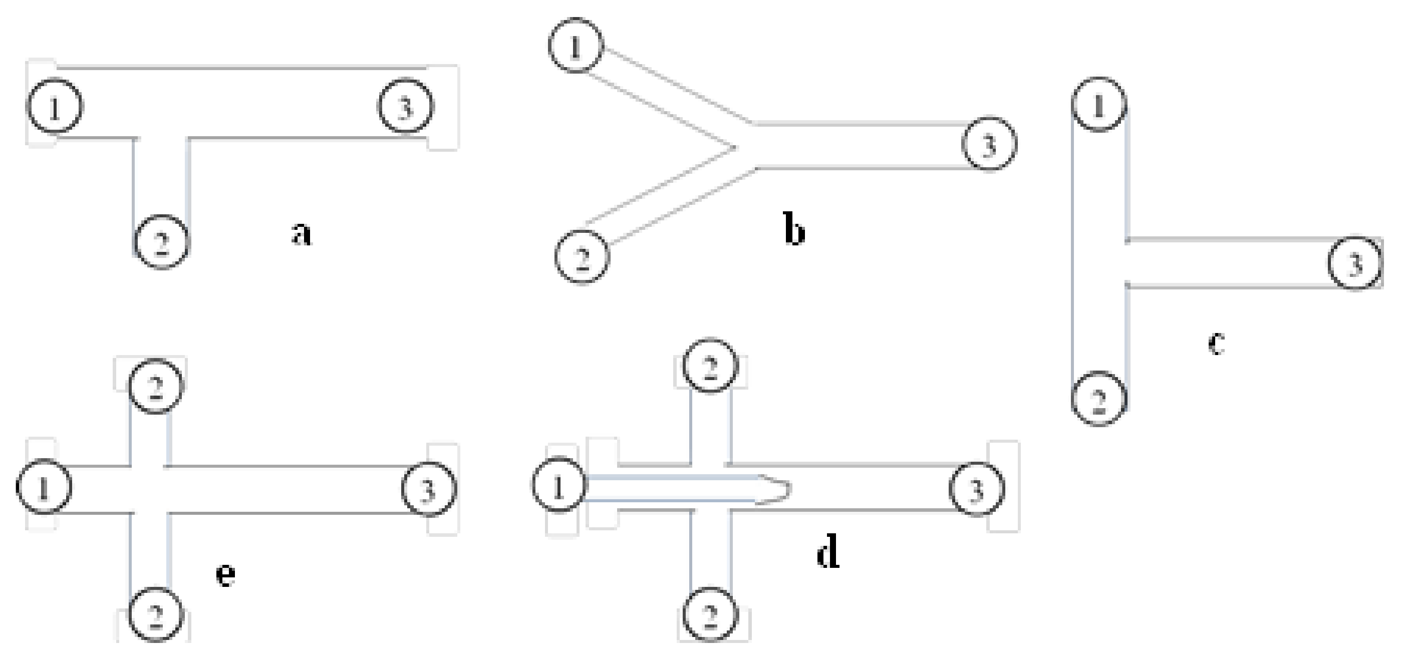
| Authors | Channel (CH) Details | Type of Study | System | Flow Regime | Equipment Used | ||||
|---|---|---|---|---|---|---|---|---|---|
| Geometry Type | CH Diameter/Size (mm) | CH Length (mm) | CH Material | Flow Rate/Velocity (m/s) | Experimental/CFD | ||||
| Su et al. [23] | Square microchannel | 0.6 × 0.6 | 2 | NA | 0.6 mL/min | Experimental | Glycerol-kerosene; Oil soluble surfactant Span 80 | Slug flow | High Speed CMOS Camera system (Basler A504KC) |
| Kashid and Kiwi-Minsker [24] | T-square; Y-rectangular; Trapezoidal; Concentric | 0.4 × 0.4 0.5 × 0.4 0.25 × 0.292 d = 0.5 | 56 75 40 200 | NA | 5.8 × 10⁻³ m3/s; 0.025 m/s | Experimental | Water- Toluene | Slug flow; Transition flow; Annular/Parallel flow | High Speed Camera |
| Kovalev et al. [8] | T-junction | 0.12 × 0.12 0.24 × 0.12 | 11.5; 22.5 | SU-8 | (2 < Qc < 6 1.5 < Qc < 20) μL/min | Experimental | Castor oil-Distilled water | Plug flow; Plug flow with suspended particles; Droplet Flow; Throat annular; Slug flow; Parallel Flow | High Speed Camera; Particle Tracking Velocimetry |
| Svensson et al. [25] | Square microchannel | 0.6 × 0.6 0.4 × 0.4 0.6 × 0.3 | 5 | Glass | Qc = 8 mL/h; Qd = 2 mL/h | Experimental | Water-n-hexane | Slug flow | High Speed Camera |
| Vansteene et al. [26] | T, X Junction microchannel | 0.1 × 0.1 | 1.125 | Glass | 5.8 × 10⁻³ < Qd< 0.033 mL/h; 0.07 < Qc < 11 | Experimental | Water, dodecane, nitric acid, Hydrochloric acid, DMDBTDMA | Segmented/Slug flow | High Speed Camera mini AX 100 |
| Li et al. [27] | Y channel | 0.24 × 0.008 | 2 mm | PDMS, Glass; Quartz | 40 < ud < 400 μm/s; 100 < uc< 1000 μm/s | Experimental | Oleic acid-water | Parallel flow | TS-100S nikon Japan |
| Li et al. [28] | T-junction | 0.3 × 0.15 | 5 mm | Glass | 0.5–5 μL/min | Experimental | 55% Glycerol + 15%Span80 | Drop flow | Micro-PIV |
| Yagodnitsyna et al. [7] | T-junction microchannels | 0.2 × 0.2 0.2 × 0.4 | 22.5 | SU-8 | Experimental | Non-reactive systems: Kerosene-water ParaffinOil-water castorOil-ParaffinOil | All the different flow patterns | High Speed Camera | |
| Cao et al. [15] | Rectangular microchannelss | Hydraulic dia: 0.2, 0.4, 0.6 | 105 | Glass | 0.2–150 mm/s | Experimental | Water-butanol; Water-toluene; Water-hexane | All flow patterns described | High Speed Camera |
| Yagodnisyana et al. [29] | T-junctions | 0.12; 0.24; 0.12 0.1; 0.4; 0.2 | 11.5; 22.5 | Glass | 0.15 < uw< 580 mm/s; 0.3 < uIL < 14.5 mm/s | Experimental | Ionic-liquid—water | Plug Flow | High Speed Camera |
| Yagodnisyana et al. [30] | T-junctions | 0.2 × 0.2; 0.2 × 0.4; | 11.5; 22.5 | Glass | Flow rates not provided | Experimental | Kerosene-water; Parafin Oil water; castor Oil water | Plug Flow | Micro-PIV |
Publisher’s Note: MDPI stays neutral with regard to jurisdictional claims in published maps and institutional affiliations. |
© 2021 by the authors. Licensee MDPI, Basel, Switzerland. This article is an open access article distributed under the terms and conditions of the Creative Commons Attribution (CC BY) license (https://creativecommons.org/licenses/by/4.0/).
Share and Cite
Ganguli, A.A.; Pandit, A.B. Hydrodynamics of Liquid-Liquid Flows in Micro Channels and Its Influence on Transport Properties: A Review. Energies 2021, 14, 6066. https://doi.org/10.3390/en14196066
Ganguli AA, Pandit AB. Hydrodynamics of Liquid-Liquid Flows in Micro Channels and Its Influence on Transport Properties: A Review. Energies. 2021; 14(19):6066. https://doi.org/10.3390/en14196066
Chicago/Turabian StyleGanguli, Arijit A., and Aniruddha B. Pandit. 2021. "Hydrodynamics of Liquid-Liquid Flows in Micro Channels and Its Influence on Transport Properties: A Review" Energies 14, no. 19: 6066. https://doi.org/10.3390/en14196066