
High-Temperature Chloride-Carbonate Phase Change Material: Thermal Performances and Modelling of a Packed Bed Storage System for Concentrating Solar Power Plants

 , ,
, ,  , and
, and
Abstract
:
1. Introduction
- Suitable phase change temperature;
- Large phase change enthalpy (at least 50 kJ/kg);
- Complete reversibility and good cycling stability avoiding phases separation;
- Little sub-cooling to assure that melting and solidification can proceed to a narrow temperature range;
- Good thermal conductivity;
- Low vapour pressure;
- Small volume change;
- Chemical stability;
- Compatibility with the vessel and the surrounding materials;
- Safe, non-toxic and non-flammable species;
- High availability of materials at acceptable cost;
- Positive life cycle assessment (LCA).
2. Materials and Methods
2.1. Sample Preparation
2.2. Experimental Measurements
2.3. Modelling Numerical Method and Governing Equations
- Tank walls are adiabatic and heat losses are neglected;
- PCM and HTF temperatures change only along the direction in which the HTF flows;
- Averaged thermo-physical properties of PCM and HTF are assumed as constant and independent of the temperature variation.
3. Results
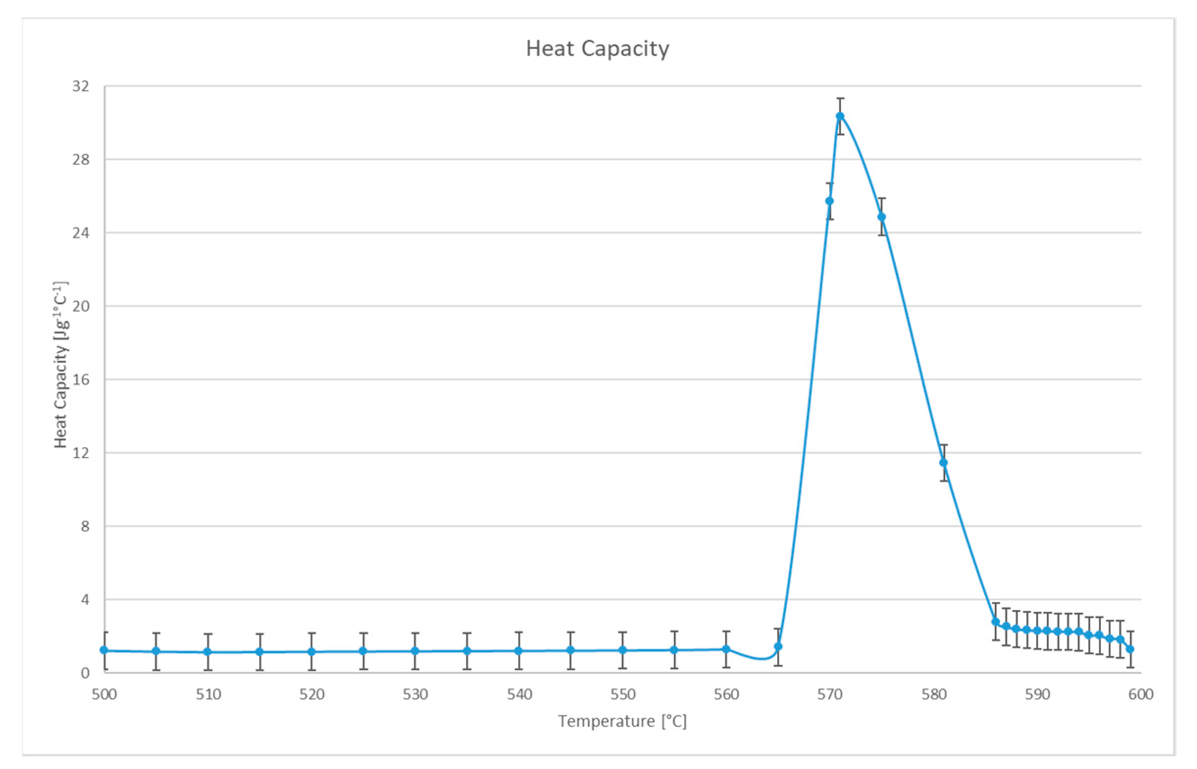
3.1. Experimental Results
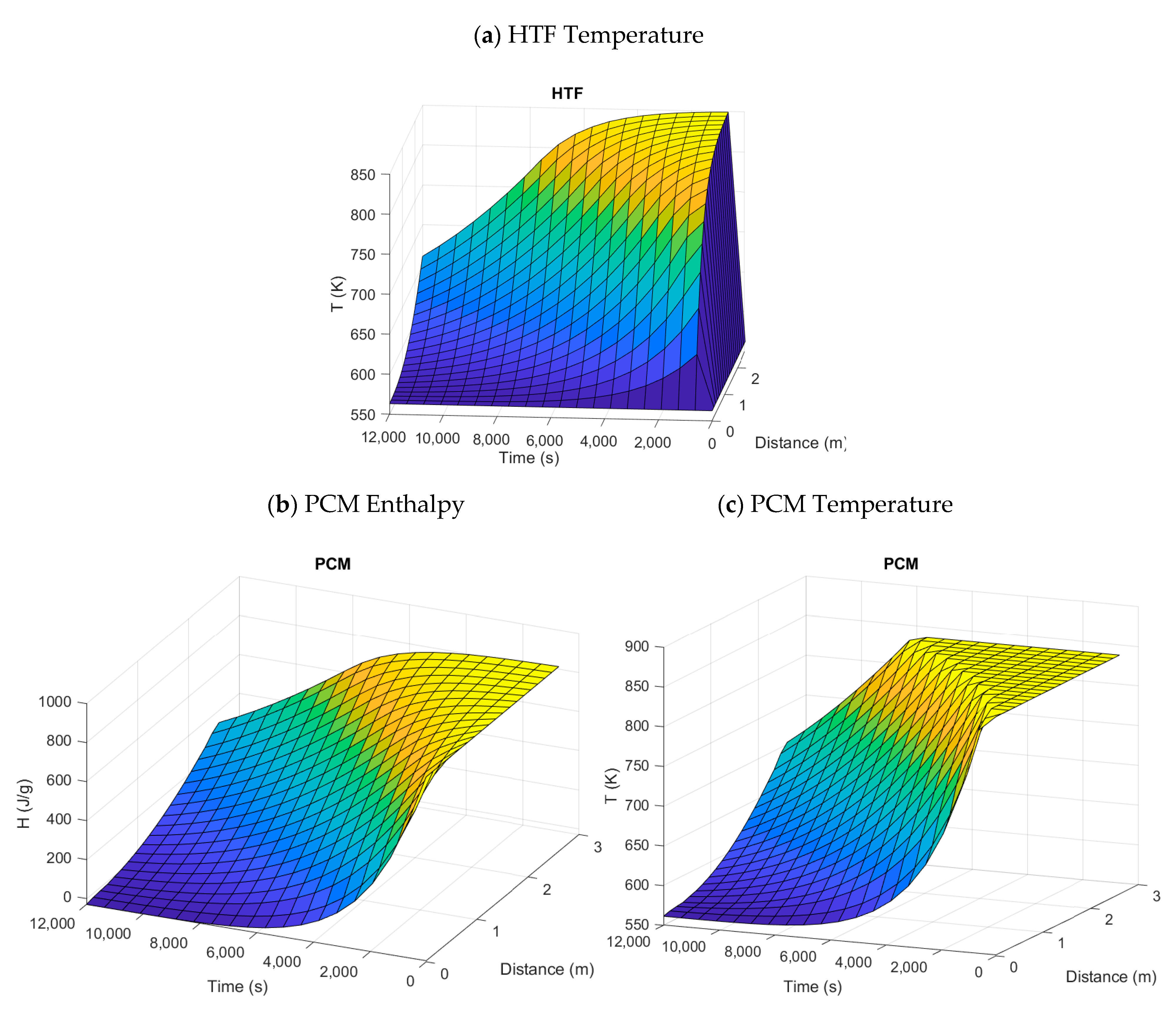
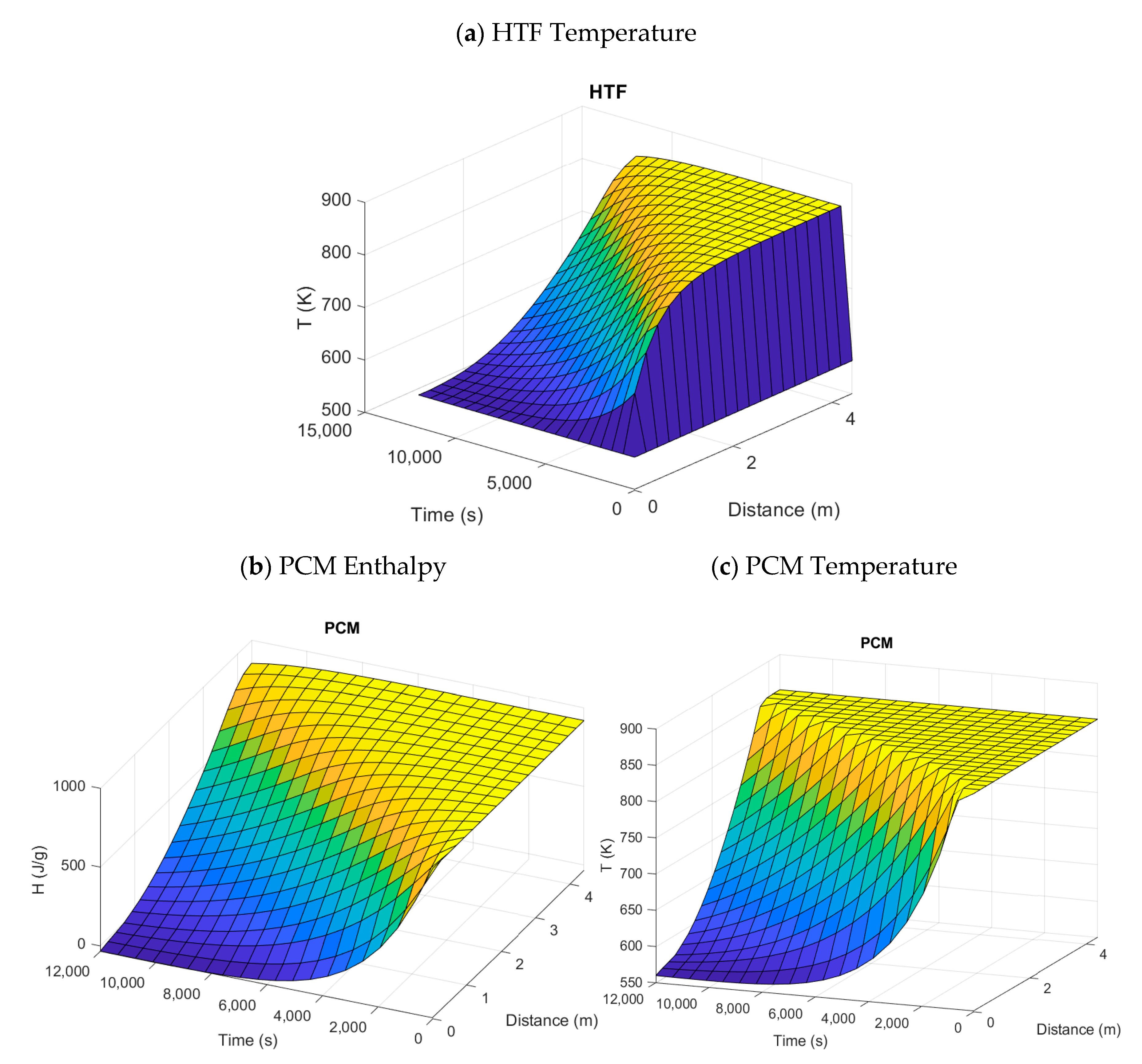
3.2. Simulation Results
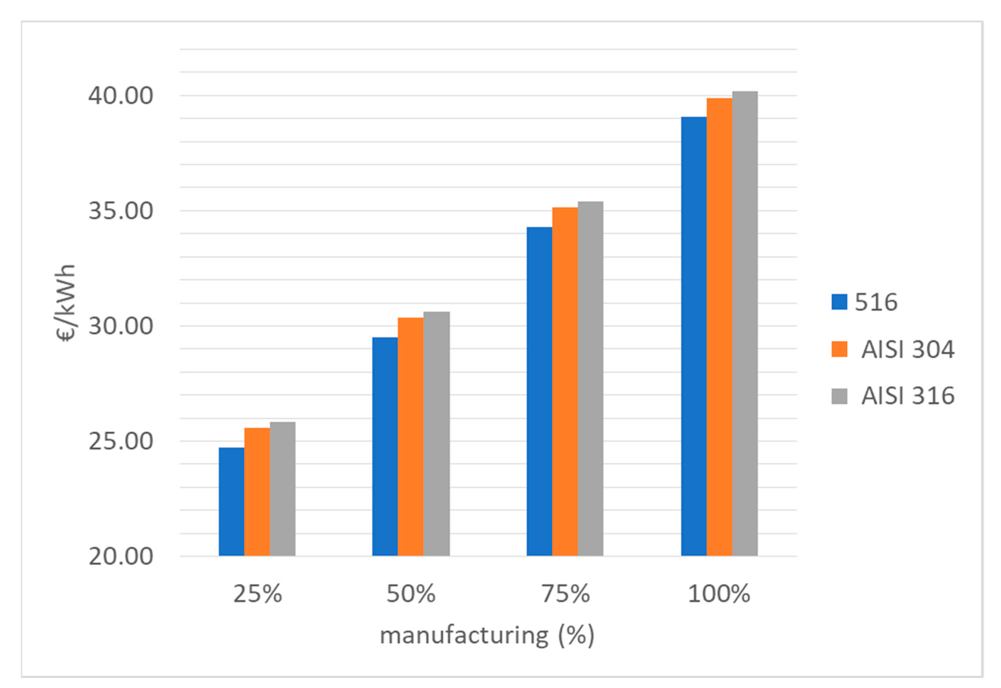
3.3. Cost Analysis
4. Conclusions
Author Contributions
Funding
Institutional Review Board Statement
Informed Consent Statement
Data Availability Statement
Conflicts of Interest
Glossary
| Nomenclature | Units | |
| Density | ||
| Specific heat | ||
| Thermal conductivity | ||
| Void fraction of packed bed | ||
| Velocity | ||
| Convective coefficient of heat transfer | ||
| Convectivity factor | (1/m) | |
| Temperature | T | K |
| Time | t | s |
| Enthalpy | H | |
| Dynamic viscosity | Pa s | |
| Cross section area of the cylindrical tank | ||
| Reciprocal of thermal exchange coefficient | ||
| Thickness | s | (m) |
| Mass flow rate | (kg/s) | |
| Radius of capsule | r | (m) |
| Radius of tank | R | |
| Dynamic viscosity | Pa* s |
References
- IRENA Renewable Energy Statistics. Available online: https://www.irena.org/publications/2020/Jul/Renewable-energy-statistics-2020 (accessed on 24 August 2021).
- Sawin, J.L.; Martinot, E. Renewables bounced back in 2010, REN21. 2011. Renewables 2011 Global Status Report. Available online: https://www.ren21.net/wp-content/uploads/2019/05/GSR2011_Full-Report_English.pdf (accessed on 24 August 2021).
- Chu, Y.; Meisen, P. Review and Comparison of Different Solar Energy Technologies; Global Energy Network Institute (GENI): San Diego, CA, USA, 2011. [Google Scholar]
- Sharan, P.; Turchi, C.; Kurup, P. Optimal design of phase change material storage for steam production using annual simulation. Sol. Energy 2019, 185, 494–507. [Google Scholar] [CrossRef]
- Prieto, C.; Rodríguez, A.; Patiño, D.; Cabeza, L.F. Thermal energy storage evaluation in direct steam generation solar plants. Sol. Energy 2018, 159, 501–509. [Google Scholar] [CrossRef] [Green Version]
- Da Cunha, J.; Eames, P. Thermal energy storage for low and medium temperature applications using phase change materials—A review. Appl. Energy 2016, 177, 227–238. [Google Scholar] [CrossRef] [Green Version]
- Liu, D.; Xin-Feng, L.; Bo, L.; Si-Quan, Z.; Yan, X. Progress in thermochemical energy storage for concentrated solar power: A review. Int. J. Energy Res. 2018, 42, 4546–4561. [Google Scholar] [CrossRef]
- IEA. World Energy Outlook 2019—Analysis; IEA: Paris, France.
- Shuiqing, Z.; Ye, W.; Jiemin, Z.; Ying, Y.; Yannan, L.; Shujuan, L. Determination of thermal conductivity of inorganic salts at the liquid/solid phase transition point. In Proceedings of the 2013 Fourth International Conference on Digital Manufacturing & Automation, Qingdao, China, 9–30 June 2013; pp. 477–480. [Google Scholar]
- Zalba, B.; Marín, J.M.; Cabeza, L.F.; Mehling, H. Review on thermal energy storage with phase change: Materials, heat transfer analysis and applications. Appl. Therm. Eng. 2003, 23, 251–283. [Google Scholar] [CrossRef]
- Xu, B.; Li, P.; Chan, C.; Tumilowicz, E. General volume sizing strategy for thermal storage system using phase change material for concentrated solar thermal power plant. Appl. Energy 2015, 140, 256–268. [Google Scholar] [CrossRef] [Green Version]
- Sharma, A.; Tyagi, V.V.; Chen, C.R.; Buddhi, D. Review on thermal energy storage with phase change materials and applications. Renew. Sustain. Energy Rev. 2009, 13, 318–345. [Google Scholar] [CrossRef]
- Gomez-Vidal, J.; Tirawat, R. Corrosion of alloys in a chloride molten salt (NaCl-LiCl) for solar thermal technologies. Sol. Energy Mater. Sol. Cells 2016, 157, 234–244. [Google Scholar] [CrossRef] [Green Version]
- Forum, S.F.-M.S. Corrosion of Structural Materials in Molten Carbonate Fuel Cells: An Overview; Molten Salt Forum; Trans Tech Publications: Bäch SZ, Switzerland, 2003; Volume 7, pp. 135–154. [Google Scholar]
- Hoshi, A.; Mills, D.R.; Bittar, A.; Saitoh, T.S. Screening of high melting point phase change materials (PCM) in solar thermal concentrating technology based on CLFR. Sol. Energy 2005, 79, 332–339. [Google Scholar] [CrossRef]
- Li, Q.; Li, C.; Du, Z.; Jiang, F.; Ding, Y. A review of performance investigation and enhancement of shell and tube thermal energy storage device containing molten salt based phase change materials for medium and high temperature applications. Appl. Energy 2019, 255, 113806. [Google Scholar] [CrossRef]
- Delise, T.; Tizzoni, A.; Ferrara, M.; Corsaro, N.; D’Ottavi, C.; Sau, S.; Licoccia, S. Thermophysical, environmental, and compatibility properties of nitrate and nitrite containing molten salts for medium temperature CSP applications: A critical review. J. Eur. Ceram. Soc. 2019, 39, 92–99. [Google Scholar] [CrossRef]
- Lin, Y.; Alva, G.; Fang, G. Review on thermal performances and applications of thermal energy storage systems with inorganic phase change materials. Energy 2018, 165, 685–708. [Google Scholar] [CrossRef]
- Galione, P.; Perez-Segarra, C.-D.; Rodríguez, I.; Oliva, A.; Rigola, J. Multi-layered solid-PCM thermocline thermal storage concept for CSP plants. Numerical analysis and perspectives. Appl. Energy 2015, 142, 337–351. [Google Scholar] [CrossRef] [Green Version]
- Feldhoff, J.F.; Schmitz, K.; Eck, M.; Schnatbaum-Laumann, L.; Laing, D.; Ortiz-Vives, F.; Schulte-Fischedick, J. Comparative system analysis of direct steam generation and synthetic oil parabolic trough power plants with integrated thermal storage. Sol. Energy 2012, 86, 520–530. [Google Scholar] [CrossRef] [Green Version]
- Elfeky, K.; Ahmed, N.; Wang, Q. Numerical comparison between single PCM and multi-stage PCM based high temperature thermal energy storage for CSP tower plants. Appl. Therm. Eng. 2018, 139, 609–622. [Google Scholar] [CrossRef]
- Delise, T.; Tizzoni, A.; Menale, C.; Telling, M.; Bubbico, R.; Crescenzi, T.; Corsaro, N.; Sau, S.; Licoccia, S. Technical and economic analysis of a CSP plant presenting a low freezing ternary mixture as storage and transfer fluid. Appl. Energy 2020, 265, 114676. [Google Scholar] [CrossRef]
- Kuravi, S.; Trahan, J.; Goswami, D.Y.; Rahman, M.M.; Stefanakos, E.K. Thermal energy storage technologies and systems for concentrating solar power plants. Prog. Energy Combust. Sci. 2013, 39, 285–319. [Google Scholar] [CrossRef]
- Myers, P.; Goswami, D.Y. Thermal energy storage using chloride salts and their eutectics. Appl. Therm. Eng. 2016, 109, 889–900. [Google Scholar] [CrossRef] [Green Version]
- Ferrer, G.; Solé, A.; Barreneche, C.; Martorell, I.; Cabeza, L.F. Corrosion of metal containers for use in PCM energy storage. Renew. Energy 2015, 76, 465–469. [Google Scholar] [CrossRef] [Green Version]
- Regin, A.F.; Solanki, S.; Saini, J. Heat transfer characteristics of thermal energy storage system using PCM capsules: A review. Renew. Sustain. Energy Rev. 2008, 12, 2438–2458. [Google Scholar] [CrossRef]
- Schumann, T. Heat transfer: A liquid flowing through a porous prism. J. Frankl. Inst. 1929, 208, 405–416. [Google Scholar] [CrossRef]
- Ismail, K.; Henríquez, J. Numerical and experimental study of spherical capsules packed bed latent heat storage system. Appl. Therm. Eng. 2002, 22, 1705–1716. [Google Scholar] [CrossRef]
- Peng, H.; Dong, H.; Ling, X. Thermal investigation of PCM-based high temperature thermal energy storage in packed bed. Energy Convers. Manag. 2014, 81, 420–427. [Google Scholar] [CrossRef]
- Bellan, S.; Alam, T.E.; González-Aguilar, J.; Romero, M.; Rahman, M.M.; Goswami, D.; Stefanakos, E.K. Numerical and experimental studies on heat transfer characteristics of thermal energy storage system packed with molten salt PCM capsules. Appl. Therm. Eng. 2015, 90, 970–979. [Google Scholar] [CrossRef]
- Sau, S.; Corsaro, N.; Crescenzi, T.; D’Ottavi, C.; Liberatore, R.; Licoccia, S.; Russo, V.; Tarquini, P.; Tizzoni, A. Techno-economic comparison between CSP plants presenting two different heat transfer fluids. Appl. Energy 2016, 168, 96–109. [Google Scholar] [CrossRef]
- Ávila-Marín, A.L. Volumetric receivers in solar thermal power plants with central receiver system technology: A review. Sol. Energy 2011, 85, 891–910. [Google Scholar] [CrossRef]
- Good, P.; Zanganeh, G.; Ambrosetti, G.; Barbato, M.; Pedretti, A.; Steinfeld, A. Towards a commercial parabolic trough CSP system using air as heat transfer fluid. Energy Procedia 2014, 49, 381–385. [Google Scholar] [CrossRef] [Green Version]
- Pitz-Paal, R.; Jürgen, D.; Milow, B. (Eds.) SES6-CT ECOSTAR. European Concentrated Solar Thermal Deliverable No. 7 Roadmap Document. Available online: https://www.vgb.org/vgbmultimedia/roadmap252-p-1723.pdf (accessed on 24 August 2021).
- Boretti, A.; Castelletto, S.; Al-Zubaidy, S. Concentrating solar power tower technology: Present status and outlook. Nonlinear Eng. 2018, 8, 10–31. [Google Scholar] [CrossRef]
- Reyes-Belmonte, M.A.; Pino, F.J.; Romero, M.; Suarez, C.; González-Aguilar, J.; Guerra, J. Optimization of an integrated solar combined cycle. AIP Conf. Proc. 2018, 2033, 210012. [Google Scholar] [CrossRef]
- Lanchi, M.; Turchetti, L.; Sau, S.; Liberatore, R.; Cerbelli, S.; Murmura, M.A.; Annesini, M.C. A Discussion of possible approaches to the integration of thermochemical storage systems in concentrating solar power plants. Energies 2020, 13, 4940. [Google Scholar] [CrossRef]
- Ellingwood, K.; Safdarnejad, S.M.; Rashid, K.; Powell, K. Leveraging energy storage in a solar-tower and combined cycle hybrid power plant. Energies 2018, 12, 40. [Google Scholar] [CrossRef] [Green Version]
- Kruizenga, A.M. Corrosion Mechanisms in Chloride and Carbonate Salts; Report No. SAND2012-7594; Sandia National Laboratories: Livermore, CA, USA.
- Yaokawa, J.; Oikawa, K.; Anzai, K. Thermodynamic assessment of the KCl–K2CO3–NaCl–Na2CO3 system. Calphad 2007, 31, 155–163. [Google Scholar] [CrossRef]
- Tumilowicz, E.; Chan, C.L.; Li, P.; Xu, B. An enthalpy formulation for thermocline with encapsulated PCM thermal storage and benchmark solution using the method of characteristics. Int. J. Heat Mass Transf. 2014, 79, 362–377. [Google Scholar] [CrossRef] [Green Version]
- Van Lew, J.; Li, P.; Chan, C.L.; Karaki, W.; Stephens, J. Analysis of heat storage and delivery of a thermocline tank having solid filler material. J. Sol. Energy Eng. 2011, 133, 021003. [Google Scholar] [CrossRef]
- Xu, B.; Li, P.; Chan, C. Application of phase change materials for thermal energy storage in concentrated solar thermal power plants: A review to recent developments. Appl. Energy 2015, 160, 286–307. [Google Scholar] [CrossRef]
- Gage, S.; Sharan, P.; Turchi, C.; Netter, J. Evaluation of formate salt PCM’s for latent heat thermal energy storage. Energies 2021, 14, 765. [Google Scholar] [CrossRef]
- Andersson, P. Thermal conductivity under pressure and through phase transitions in solid alkali halides. I. Experimental results for KCl, KBr, KI, RbCl, RbBr and RbI. J. Phys. C: Solid State Phys. 1985, 18, 3943–3955. [Google Scholar] [CrossRef]
- Deng, Z.F.; Liu, Z.H.; Zhang, G.Q.; Xu, G.Z.; Yang, C.Y. Effect of humidity environment on properties of molten salt phase change materials. In Proceedings of the IOP Conference Series: Materials Science and Engineering, the 2nd International Workshop on Materials Science and Mechanical Engineering (IWMSME2018), Qingdao, China, 26–28 October 2018; IOP Publishing: Bristol, UK, 2019; Volume 504, p. 012010. [Google Scholar]
- Perry, R.H.; Green, D.W. Perry’s Chemical Engineers’ Handbook; McGraw-Hill: New York, NY, USA, 2008. [Google Scholar]
- Romero, M.; Buck, R.; Pacheco, J.E. An update on solar central receiver systems, projects, and technologies. J. Sol. Energy Eng. 2002, 124, 98–108. [Google Scholar] [CrossRef]
- Rhodes, M. Introduction to Particle Technology; John Wiley & Sons: Hoboken, NJ, USA, 2008. [Google Scholar]
- Li, P.; van Lew, J.; Chan, C.; Karaki, W.; Stephens, J.; O’Brien, J. Similarity and generalized analysis of efficiencies of thermal energy storage systems. Renew. Energy 2012, 39, 388–402. [Google Scholar] [CrossRef]
- Peters, M.; Timmerhaus, K.; West, R. Plant Design and Economics for Chemical Engineers, 5th ed.; McGraw-Hill: New York, NY, USA, 2003. [Google Scholar]
- IEA-ETSAP; IRENA©. Technology Brief E17—Thermal Energy Storage-Technology Brief-January 2013; IEA-ETSAP; IRENA©; Available online: https://www.irena.org/publications/2013/Jan/Thermal-energy-storage (accessed on 24 August 2021).
- Cabeza, L.F.; Galindo, E.; Prieto, C.; Barreneche, C.; Fernandez, A.I. Key performance indicators in thermal energy storage: Survey and assessment. Renew. Energy 2015, 83, 820–827. [Google Scholar] [CrossRef] [Green Version]


| Salt Type | % wt/wt | Melting Temperature (°C) | Latent Heat (kJ/kg) | Salt Type | % wt/wt | Melting Temperature (°C) | Latent Heat (kJ/kg) |
|---|---|---|---|---|---|---|---|
| AgBr | pure | 432 | 48.8 | NaBr/MgBr2 | 45/55 | 431 | 212 |
| LiOH | pure | 462 | 873 | KCl/ZnCl2 | 54/46 | 432 | 218 |
| PbCl2 | pure | 501 | 78.7 | NaCl/MgCl2 | 48/52 | 450 | 431 |
| LiBr | pure | 550 | 203 | NaCl/CaCl2/MgCl2/KCl | 47.4/41.6/8.8/2.2 ** | 460 | 245 |
| Ca(NO3)2 | pure | 560 | 145 | KCl/NaCl/MgCl2/BaCl2 | 52.3/20.7/18.2/8.7 ** | 475 | 248 |
| Ba(NO3)2 | pure | 594 | 209 | KCl/NaCl/CaCl2/BaCl2 | 47.3/22.7/16.9/13.1 ** | 478 | 208 |
| Sr(NO3)2 | pure | 608 | 221 | KCl/NaCl/CaCl2/BaCl2 | 42.7/25.8/22.2/9.3 | 479 | 217 |
| LiCl | pure | 610 | 441 | Li2CO3/K2CO3 | 47/53 | 488 | 342 |
| CsBr | pure | 638 | 105 | Na2CO3/Li2CO3 | 56/44 | 496 | 370 |
| CsCl2 | pure | 645 | 121 | Na2CO3/Li2CO3 | 72/28 | 498 | 263 |
| FeCl2 | pure | 677 | 338 | NaCl/CaCl2 | 33/67 | 500 | 281 |
| RbBr | pure | 692 | 141 | CaCl2/NaCl/KCl | 66/29/5 | 504 | 279 |
| CsF | pure | 693 | 143 | BaCl2/KCl/NaCl | 53/28/19 | 542 | 221 |
| MgBr2 | pure | 711 | 214 | LiCl/MgF2 | 94.5/5.5 ** | 573 | 131 |
| MgCl2 | pure | 714 | 454 | KF/KCl | 55/45 ** | 605 | 407 |
| RbCl | pure | 719 | 198 | NaCl/Na2MoO4/NaBr | 38.5/38.5/23 ** | 612 | 168 |
| Li2CO3 | pure | 732 | 509 | NaF/LiF/CaF2 | 38.3/35.2/26.5 ** | 615 | 636 |
| KBr | pure | 734 | 215 | LiF/NaF/CaF2 | 52/35/13 ** | 615 | 640 |
| CaBr2 | pure | 736 | 145 | CaCl2/CaSO4/CaMoO4 | 38.5/11.5/50 | 673 | 224 |
| NaBr | pure | 749 | 225 | NaCl/NaF | 66.5/33.5 ** | 675 | 572 |
| KCl | pure | 771 | 248 | Na2CO3/K2CO3 | 52.2/47.8 | 710 | 176 |
| CaCl2 | pure | 772 | 353 | Na2CO3/K2CO3 | 50/50 | 710 | 163 |
| RbF | pure | 774 | 253 | Na2CO3/K2CO3 | 49/51 | 710 | 782 |
| NaCl | pure | 802 | 482 | LiF/MgF2/KF | 64/30/6 ** | 710 | 790 |
| PbF2 | pure | 824 | 60 | LiF/CaF2 | 80.5/19.5 ** | 767 | 650 |
| LiF | pure | 845 | 1044 | NaF/MgF2/KF | 64/20/16 ** | 804 | 543 |
| Na2CO3 | pure | 854 | 275.7 | NaF/MgF2 | 75/25 ** | 832 | 627 |
| Li2SO4 | pure | 858 | 84 | CaF2/CaSO4/CaMoO4 | 49/41.4/9.6 ** | 943 | 237 |
| KF | pure | 858 | 468 | ||||
| Na2SO4 | pure | 884 | 165 | ||||
| K2CO3 | pure | 897 | 235.8 | ||||
| BaCl2 | pure | 961 | 76 | ||||
| K2CrO4 | pure | 973 | 170 | ||||
| NaF | pure | 996 | 794 | ||||
| PbSO4 | pure | 1000 | 133 |
| PCM Type (wt %) | Melting Point (°C) | Latent Heat (kJ/kg) | Energy Density (MJ/m3) |
|---|---|---|---|
| MgCl2-NaCl (38.5/61.5) | 435 | 351 | 870 |
| Na2CO3-Li2CO3 (56/44) | 496 | 370 | 858 |
| NaF-MgF2 (75/25) | 650 | 860 | 2425 |
| MgCl2 | 714 | 452 | 967 |
| LiF-CaF2 (80.5/19.5) | 767 | 816 | 1950 |
| NaCl | 800 | 492 | 1062 |
| Na2CO3 | 854 | 276 | 698 |
| K2CO3 | 897 | 236 | 540 |
| Equation | Units | |
|---|---|---|
| (1) | ||
| M | (2) | |
| (3) | ||
| (4) | ||
| (5) | ||
| (6) | ||
| (7) | ||
| (8) | ||
| (9) | ||
| (10) |
| HTF (air) | (11) | |
| PCM | (12) |
| HTF | |
| PCM |
| Parameter | Value | Unit |
|---|---|---|
| Tair_in | 290 | °C |
| Tair_out | 550 | °C |
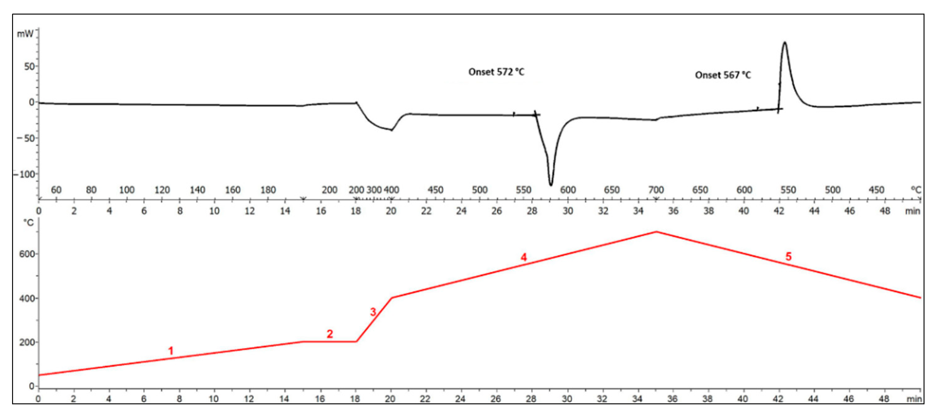
| TPCM_melt | 572 | °C |
| 2.5144 | ||
| 1.0748 | ||
| Pa s | ||
| 1935 | ||
| 2.6 | ||
| 0.56 | ||
| 195.5 |
| Number of Tanks | 1 | |
|---|---|---|
| Tank Section area | 166.7 | m2 |
| Tank Radius | 7.29 | m |
| Tank Height | 6 | m |
| Tank Volume | 500 | m3 |
| Volume of the PCM inside | 304 | m3 |
| Weight of the PCM inside | 587.7 | tons |
| 0.3 | ||
| T_in PCM | 851 | K |
| T_in PCM | 573 | K |
| T_in AIR | 563 | K |
| T_out AIR | 823 | K |
| HTF mass flow | 65.2 | m3/s |
| HTF velocity | 1.3 | m/s |
| Reynold number | 2060 | |
| Discharging heat | 94.3 | GJ |
| Discharging time (3 h) | 10,800 | s |
| Discharging power | 50 | MW |
| Units | Total Cost in EUR | ||
|---|---|---|---|
| Total PCM weight | 587,723 | kg | |
| Storage efficiency | 60% | ||
| Actual PCM weight needed | 763,277 | kg | |
| Actual PCM cost | 230,406 | ||
| Sphere diameter | 5 | cm | |
| Al thickness | 0.0040 | m | |
| Total number of spheres | 6,650,113 | ||
| Total Al weight | 1,409,491 | kg | 2,635,749 |
| Tank radius | 7.29 | m | |
| Tank height | 6.00 | m | |
| Tank volume | 1000 | m3 | |
| Total costs: tank + PCM | |||
| With SA516 gr 70 | 128,127 | ||
| With AISI 304 | 253,585 | ||
| With AISI 3016 | 293,625 | ||
| PCM manufacturing impact on the total cost | 25% | ||
| Total cost including PCM manufacturing | |||
| With SA516 gr 70 | 3,710,821 | ||
| With AISI 304 | 3,836,279 | ||
| With AISI 3016 | 3,876,319 | ||
| Investment costs per electric power and electric energy | |||
| Cost EUR/kW with SA516 gr 70 | 74.22 EUR/kW | ||
| Cost EUR/kWh with SA516 gr 70 | 24.74 EUR/kWh | ||
| Cost EUR/kW with AISI 304 | 76.73 EUR/kW | ||
| Cost EUR/kWh with AISI 304 | 25.58 EUR/kWh | ||
| Cost EUR/kW with AISI 316 | 77.53 EUR/kW | ||
| Cost EUR/kWh with AISI 316 | 25.84 EUR/kWh | ||
| PCM Manufacturing Cost (%) | 25% | 50% | 75% | 100% |
|---|---|---|---|---|
| EUR/kWh | ||||
| SA516 gr 70 | 24.74 | 29.52 | 34.29 | 39.07 |
| AISI 304 | 25.58 | 30.35 | 35.13 | 39.91 |
| AISI 3016 | 25.84 | 30.62 | 35.40 | 40.17 |
Publisher’s Note: MDPI stays neutral with regard to jurisdictional claims in published maps and institutional affiliations. |
© 2021 by the authors. Licensee MDPI, Basel, Switzerland. This article is an open access article distributed under the terms and conditions of the Creative Commons Attribution (CC BY) license (https://creativecommons.org/licenses/by/4.0/).
Share and Cite
Sau, G.S.; Tripi, V.; Tizzoni, A.C.; Liberatore, R.; Mansi, E.; Spadoni, A.; Corsaro, N.; Capocelli, M.; Delise, T.; Della Libera, A. High-Temperature Chloride-Carbonate Phase Change Material: Thermal Performances and Modelling of a Packed Bed Storage System for Concentrating Solar Power Plants. Energies 2021, 14, 5339. https://doi.org/10.3390/en14175339
Sau GS, Tripi V, Tizzoni AC, Liberatore R, Mansi E, Spadoni A, Corsaro N, Capocelli M, Delise T, Della Libera A. High-Temperature Chloride-Carbonate Phase Change Material: Thermal Performances and Modelling of a Packed Bed Storage System for Concentrating Solar Power Plants. Energies. 2021; 14(17):5339. https://doi.org/10.3390/en14175339
Chicago/Turabian StyleSau, Giovanni Salvatore, Valerio Tripi, Anna Chiara Tizzoni, Raffaele Liberatore, Emiliana Mansi, Annarita Spadoni, Natale Corsaro, Mauro Capocelli, Tiziano Delise, and Anna Della Libera. 2021. "High-Temperature Chloride-Carbonate Phase Change Material: Thermal Performances and Modelling of a Packed Bed Storage System for Concentrating Solar Power Plants" Energies 14, no. 17: 5339. https://doi.org/10.3390/en14175339