Article

The Application of Disturbance-Observer-Based Control in Breath Pressure Control of Aviation Electronic Oxygen Regulator

1
School of Aeronautic Science and Engineering, Beihang University, Beijing 100191, China
2
Hefei Jianghang Aircraft Equipment Corporation LTD. AVIC, Hefei 230051, China
3
Beijing Institute of Spacecraft Environment Engineering, Beijing 100094, China
*
Author to whom correspondence should be addressed.
Energies 2021, 14(16), 5189; https://doi.org/10.3390/en14165189
Submission received: 26 July 2021 / Revised: 13 August 2021 / Accepted: 21 August 2021 / Published: 22 August 2021
(This article belongs to the Special Issue Advances in Fluid Power Systems)

Abstract

:
The electronic oxygen regulator (EOR) is a new type of aviation oxygen equipment which uses electronic servo control technology to control breathing gas pressure. In this paper, the control method of EOR was studied, and the dynamic model of the aviation oxygen system was established. A disturbance-observer-based controller (DOBC) was designed by the backstepping method to achieve the goal of stable and fast breath pressure control. The sensitivity function was proposed to describe the effect of inspiratory flow on breath pressure. Combined with the frequency domain analysis of the input sensitivity function, the parameters of the DOBC were analyzed and designed. Simulation and experiment studies were carried out to examine the control performance of DOBC in respiratory resistance and positive pressurization process under the influence of noise and time delay in the discrete electronic control system, which could meet the aviation physiology requirements. The research results not only verified the rationality of the application of DOBC in the breath control of EOR, but also proved the effectiveness of the control parameters design method according to the frequency domain analysis, which provided an important design basis for the subsequent study of EOR.

1. Introduction

Fighter pilots need to be equipped with an aviation oxygen system to avoid the damage caused by low air pressure and oxygen deprivation at high altitude. Oxygen system consists of oxygen source, oxygen regulator, and individual equipment [1,2,3]. Oxygen regulator is the core component, and its main function is to control the oxygen supply pressure to meet the physiological and protective requirements. Physiological requirement refers to supplying oxygen according to the pilot’s breathing demand to reduce respiratory resistance and improve breathing comfort. Protective requirement refers to pressurizing the supply oxygen to prevent pilot from the harsh environment [4,5].
The mechanical oxygen regulator is the traditional type of oxygen regulator, which uses diaphragms for breath control [6]. With the development of microelectronic control technology, the concept of electronic oxygen regulator using sensor and motor was proposed to simplify the structure, improve the pilot’s breathing comfort, and provide monitoring capabilities [7]. The French company Airliquide launched the first electronic oxygen regulator for the F-35 which is the only product known to be in use [8]. In the research of civil emergency oxygen regulator, several attempts to combine mechanical control with electronic control have been made. Siska [9] retained the mechanically controlled valve but changed the valve seat from a fixed state to electronically adjustable. Therefore, this electromechanical oxygen regulator could work in two states: with electricity or no electricity. Frederic [10] designed a new kind of electromechanical oxygen regulator by parallel control of mechanical and electronic valves. In general, the aviation oxygen regulator is in the stage of transition from mechanical to electronic. Therefore, it is of great significance to carry out the research on the electronic oxygen regulator (EOR).
The difficulties in breath pressure control were analyzed in references [3,6,11]. Based on these studies and the particularity of pilot breath process, we summarize the following three points about breath pressure control. Firstly, the pilot’s breathing demand and the target pressure of control would change with the task load and physiological state, which has strong randomness and uncertainty. Secondly, the breath cycle is very short and the breath flow rate changes fast. In the normal state, the breath cycle is about 6 s, and the peak breath flow rate is about 30 L/min. During flight, the breath cycle may be shortened to about 1 s, and the peak breath flow rate may reach 180 L/min. Thirdly, due to the limitation of space, the volume of the breath chamber is small, so the breath pressure is very easy to change largely. Combined with the above characteristics, EOR needs to have fast response speed, high sensitivity, as well as a stable and robust control law [12].
So far, several studies have been conducted on EORs to improve the control performance of breath pressure. Yu et al. [13] designed an EOR driven by stepping motor and controlled by switch method. Sun et al. [14] improved research in [13] by adjusting the motor speed with fuzzy control theory. Li et al. [15] developed expert PID control for the EOR driven by voice coil motor, which solved the deficiency of fixed parameters. Jiang et al. uses a commercial flow servo valve as the executive structure of EOR to and apply generalized predictive control [16], active disturbance rejection control [17], and adaptive control [18] into breath pressure control. The results show that the intelligent control has better robustness than PID control. All the above studies were exploratory studies on control law schemes of EOR for physiological requirement, but the key to design control parameters did not be pointed out clearly. In addition, only a few of these researches took consideration into protective requirement, so the control of positive pressurization process is still to be studied.
Disturbance-observer-based control (DOBC) is a kind of control method which comprehensively estimates the external disturbance and internal model uncertainty according to the mathematical model and control input, and introduces equivalent compensation in the control to realize the complete control of disturbance. The disturbance observer is extended from the state observer in modern control in which disturbance is extended as a part of the system state. If the estimation error of the disturbance could converge gradually, the system will obtain the ability to compensate the disturbance in time with the estimation value of disturbance, and the control law can achieve great ability of disturbance rejection. DOBC has been usually adapted to supplement the commonly used method of feedback control, making the model-based control design to be applied better to the actual system and improving the robustness of the control system [19,20,21].
In this paper, a basic structure of EOR driven by hybrid stepping motor was presented, and the mathematical model of breath pressure control was established. The DOBC theory was applied to the breath pressure control of the EOR, and the external load of the pilot’s breath flow and the internal model error could be estimated and compensated. The sensitivity function of the input disturbance was used to describe the effect of pilot’s breath flow on breath pressure and analyzed in frequency domain, and the control parameters were determined by magnitude-frequency characteristics. Simulation and experiments were carried out to verify the control performance of DOBC on respiratory resistance and positive pressurization.

2. System Principle and Mathematical Model

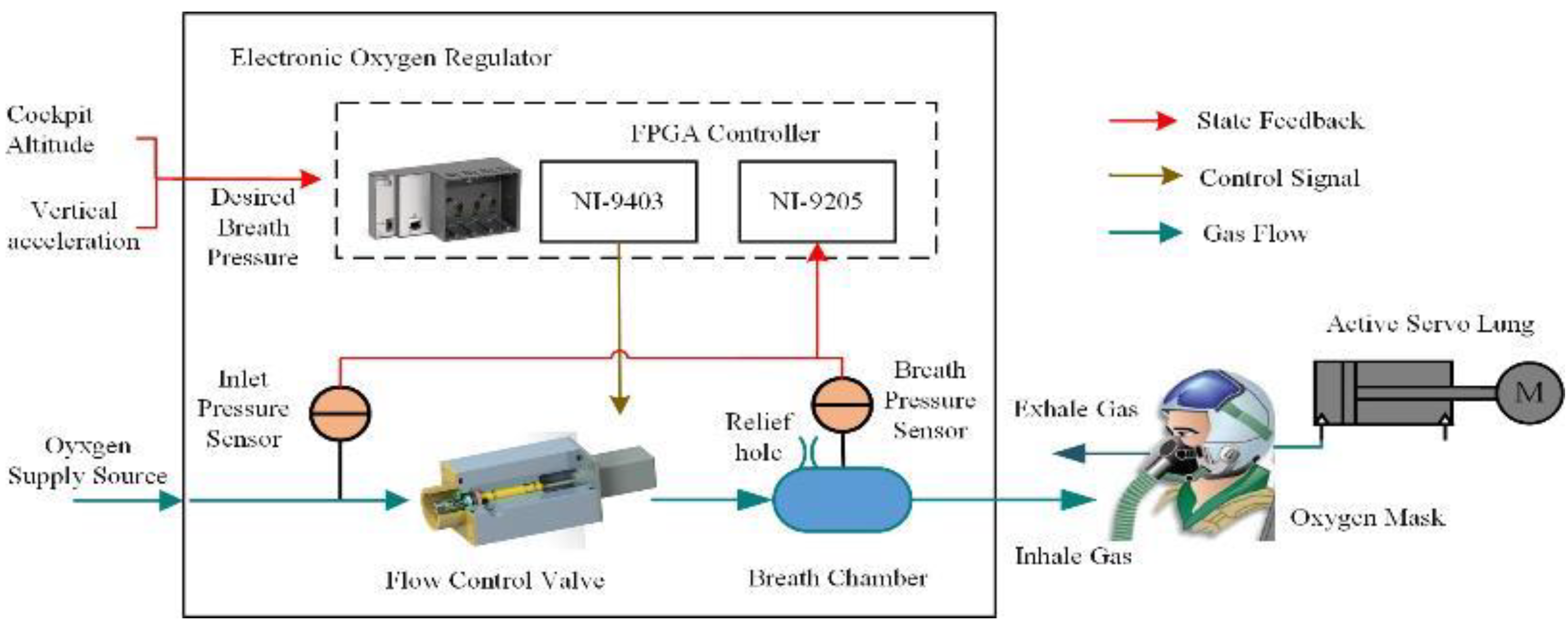
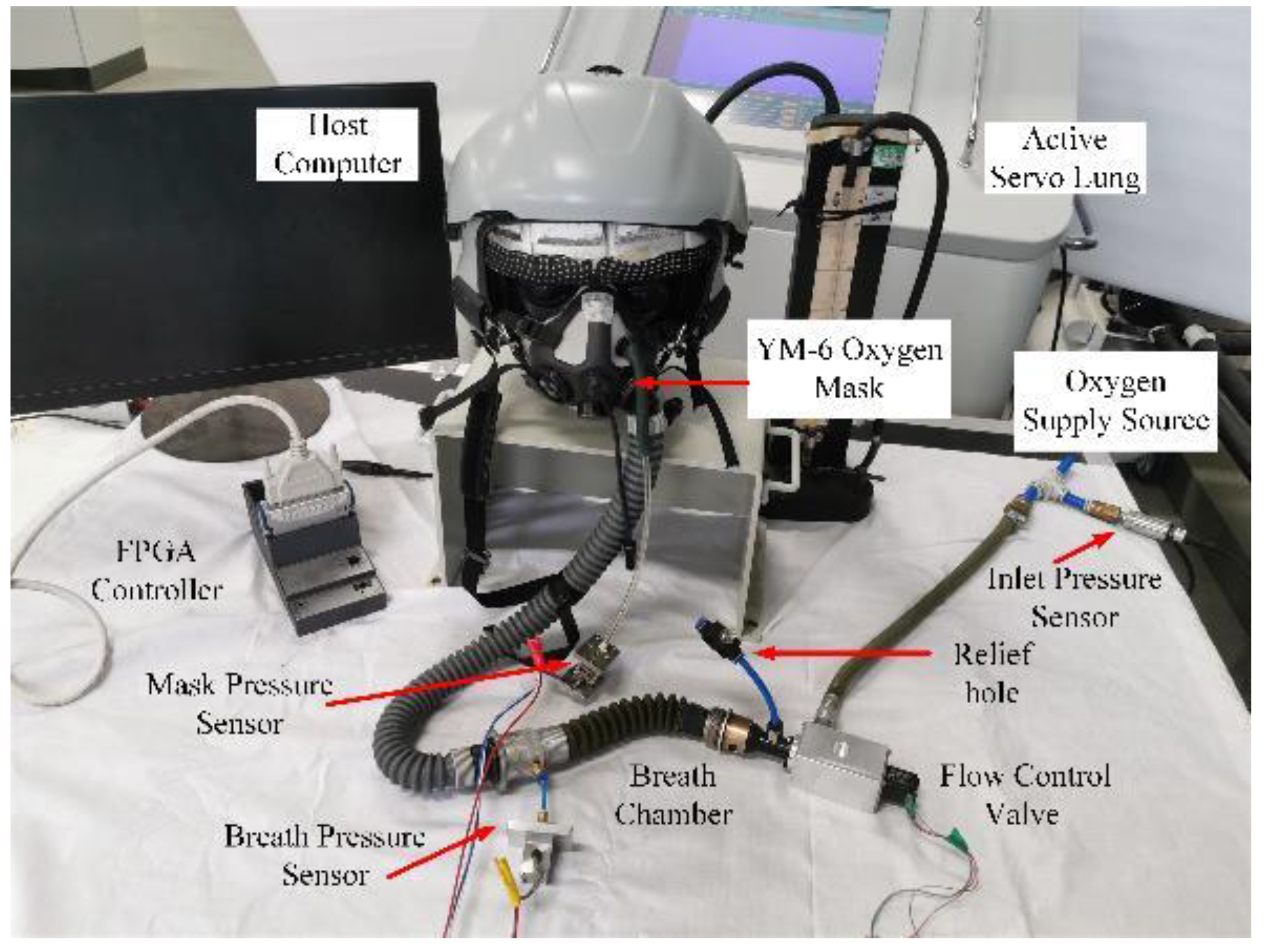
2.1. System Description

The new type of aviation oxygen system mainly includes four parts: oxygen supply source, electronic oxygen regulator, oxygen mask, and active servo lung, as shown in Figure 1. High pressure oxygen flow provided from oxygen supply source is adjusted by the EOR so that breath pressure could be keep stable around the target pressure. The oxygen mask has two check valves, one for inhalation and the other for exhalation. During breathing, the two check valves open alternately, not only saving oxygen supply, but also relief the exhaled air out of the mask. It is ensured that pilots would not repeatedly inhale the exhaled air with low oxygen concentration. Active servo lung was designed to simulate human lungs, which could intermittently inhale and exhale gas [22].
The electronic oxygen regulator mainly includes inlet pressure sensor, flow control valve, breath chamber, breath pressure sensor, and controller. The desired breath pressure was set in accordance with the cockpit height and vertical acceleration signal from external sensors, to achieve the purpose of positive breath pressure for high altitude and anti-G. When the pilot inhales, the check valve for inhalation on mask opens. Gas in the breath chamber would be breathed into the mask, and the breath pressure would drop below the desired pressure. The controller drives the flow control valve open to provide sufficient oxygen flow to the pilot to maintain breath pressure stable. When the pilot exhales, the check valve for inhalation on mask turns to close and the check valve for exhalation opens, the controller closes the flow control valve immediately to avoid excessive gas supply, affecting the pilot’s exhalation process. Relief hole on the breath chamber is used to relief excessive breath pressure.
The pressure difference between the breath pressure and the desired pressure is usually used to describe the working performance of EOR. The negative pressure difference indicates the inspiratory resistance, and the positive pressure difference indicates the expiratory resistance. In order to avoid the phenomenon of breathing fatigue, the pressure difference under control of the EOR should keep within the respiratory resistance threshold in Table 1. The control accuracy of breath pressure in positive pressurization process should reach ± 0.1 kPa in the pressurized range of 0~10 kPa to accurately realize the protective effect of pressurized oxygen supply.

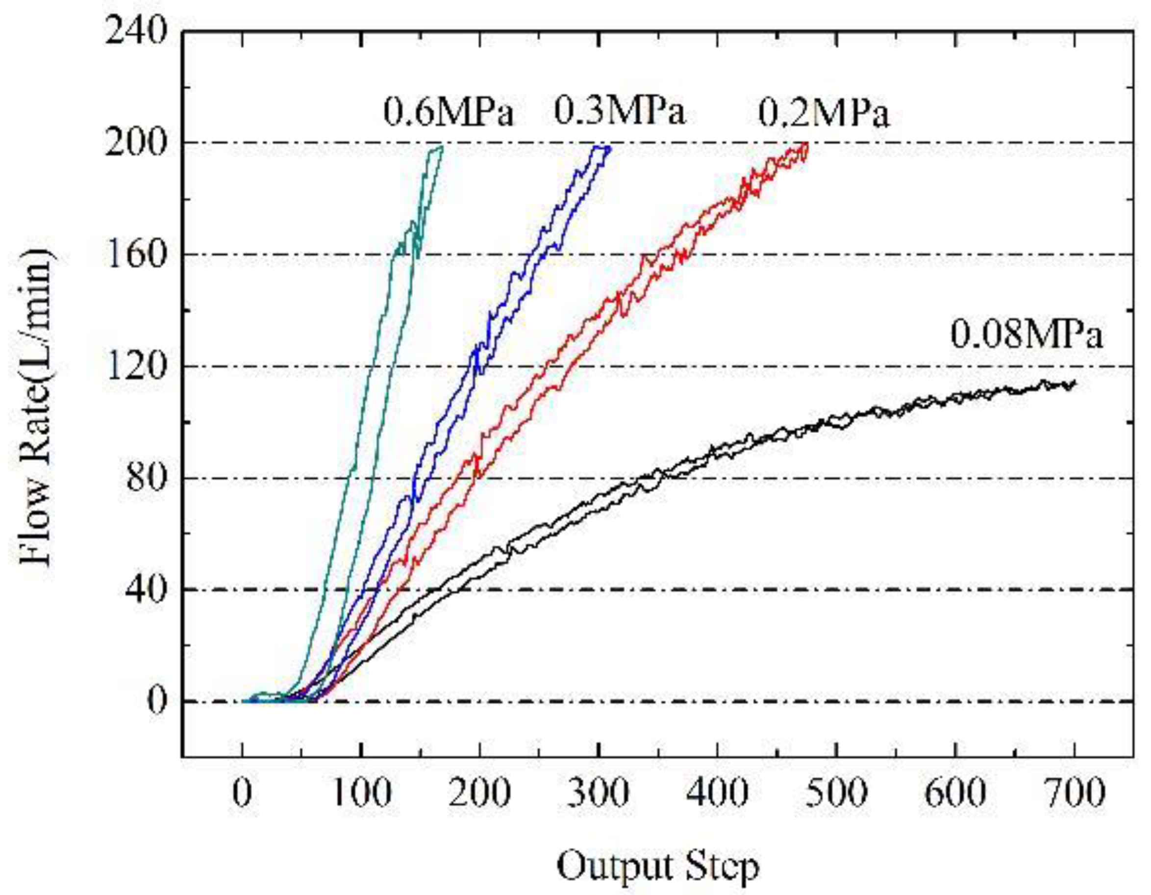
2.2. Mathematical Model

According to the characteristics of the thermal process, the following reasonable assumptions were made to simplify the model:
(1) The gas could be descried with the ideal gas state equation and the thermal process of gas in each chamber accords with the polytropic thermal process;
(2) The gas distribution in each chamber is even and pressure could be expressed by a uniform value;
(3) The flow of gas through the hole and valves was considered as the one-dimensional steady adiabatic flow.
During the working process, there will be continuous flow into and out of the breath chamber, and the exchange of mass, heat, and work exists between the system and the outside world. Therefore, the breath chamber was modeled as an open system. The control volume was selected according to the edge of the chamber, and the mathematical model of the state parameters such as pressure, temperature, and gas mass in the breath chamber were established with the mass conservation equation and the polytropic thermal process equation. According to the law of mass conservation, the mass increment in the control volume is equal to the difference between the mass into and out of the control volume. The differential form is written as
d m = δ m i n δ m o u t ,
where dm represents the gas mass increment in the breath chamber, δmin and δmout are the mass entering and leaving the system. Based on the ideal gas state equation p V = m R T , the gas mass increment could be written as
d m m = d p p + d V V d T T ,
where m, p, ρ, and T represent the mass, pressure, density, and temperature of the gas in the breath chamber, respectively; V is volume of breath chamber; and R is the gas constant. Since the volume of the breath chamber is fixed, the volume differential in the mass equation above can be ignored. According to the polytropic thermal process equation p / ρ n = c o n s t , relation between temperature and pressure could be descried as
d T T = n 1 n d p p ,
where n is the polytropic index, which was chosen as 1.35, because the polytropic process in the breath chamber is close to the adiabatic process. Combined with the Equations (1)–(3), the differential function of breath pressure could be given by
d p d t = n R T V ( δ m i n d t δ m o u t d t ) .
According to the relationship between the downstream and upstream pressure ratio and the critical pressure ratio, the mass flow through the flow control valve and relief hole can be divided into critical flow and subcritical flow. The mass flow rate of the critical flow is only determined by the upstream pressure, while the mass flow rate of the subcritical flow is affected by both upstream and downstream pressure. The mass flow model is as follows:
{ q m = μ A p i n 2 k ( k 1 ) R T i n ( ε 2 / k ε ( k + 1 ) / k ) ε = m a x ( p o u t / p i n , ε c r ) ,
where qm is the mass flow rate, kg/s; μ is the flow coefficient; A is the flow area, m2; pin and pout indicate upstream and downstream pressure, Pa; k is the adiabatic constant, with the value of 1.4. ε Refers to the pressure ratio, and εcr refers to the critical pressure ratio, with the value of 0.528. According to the condition of upstream and downstream pressure, the mass flow of the flow control valve should be calculated as critical flow, and the mass flow of the relief hole should be calculated as subcritical flow.
The human lung is innervated by the nervous system and periodically expands and contracts by the respiratory muscles. It is generally believed that the instantaneous breath flow is close to the sinusoidal process, which can be expressed as
Q B ( t ) = π V t N s i n ( 2 π 60 / N t ) ,
where QB is the instantaneous volume flow of breath, L/min. Tidal volume Vt is the amount of air inhaled or exhaled in each breath cycle, with the value of 1 L for pilots. The respiratory rate N is the number of breath cycle completed per minute. The product of tidal volume Vt and respiratory rate N becomes pulmonary ventilation volume, L/min.
Due to the presence of two check valves on the mask, only the inspiratory flow would affect the pressure in the breath chamber. Therefore, the mass flow of breath is given by
q m , B ( t ) = { ρ 60 × Q B ( t )   d u r i n g   i n h a l a t i o n   0                                   d u r i n g   e x h a l a t i o n ,
where qm,B is the instantaneous mass flow of breath from the breath chamber, g/s.
According to the above model, the mass flow variations in the breathing chamber include: control input—oxygen supply flow of the flow control valve, load disturbance—mass flow of respiration, state variable—leakage flow through the relief hole. The mathematical model of breath pressure control is
d p d t = n R T V ( q m , i n ( A ( t ) , p i n ) q m , l e a k a g e ( p ) q m , B ( t ) ) .

3. DOBC Design

In order to maintain the control stability and achieve better control accuracy of breath pressure, a disturbance-observer-based controller was designed to quickly adjust the oxygen supply flow and accurately compensate the inspiration flow and leakage.

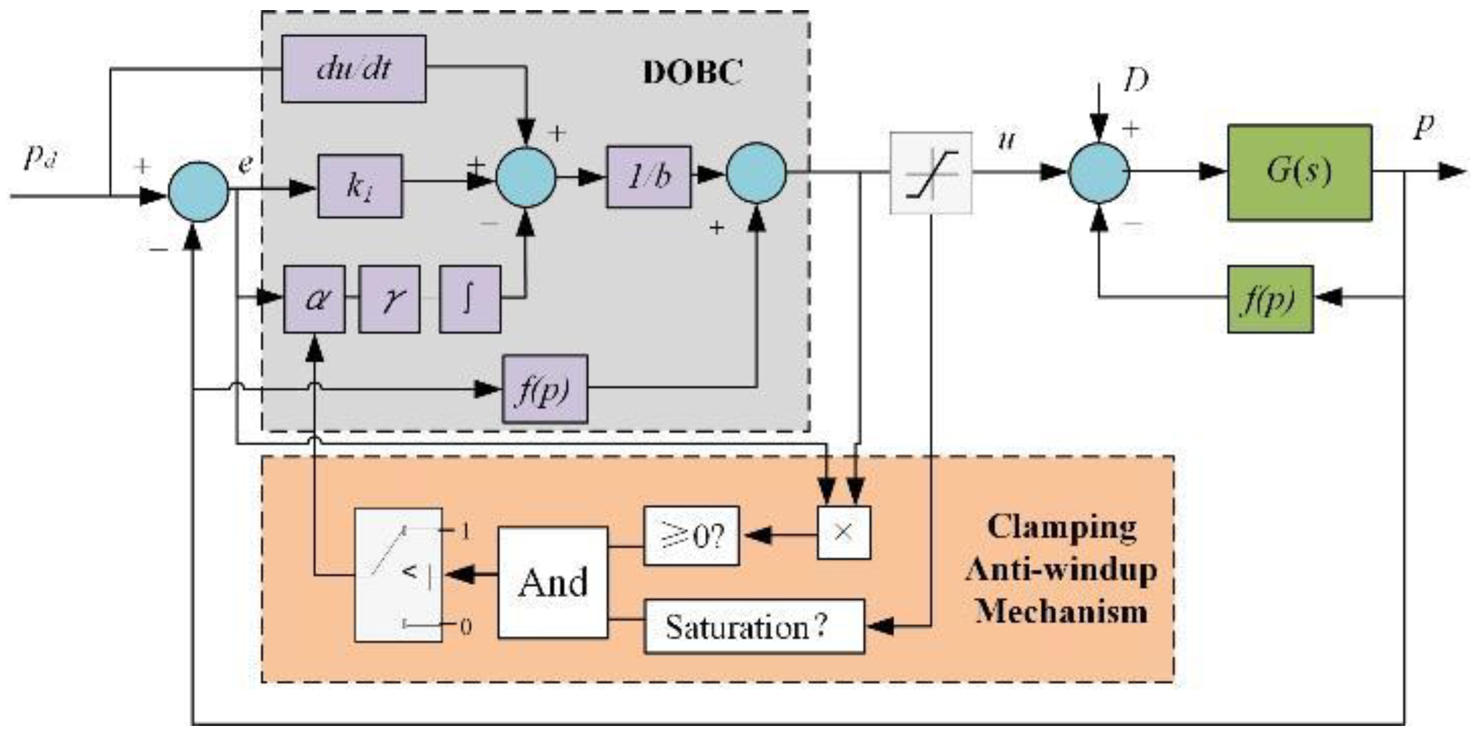
3.1. Design of Feedback Control

Let b = nRT/V, and according to the definition of mass flow variation, the differential function of breath pressure can be written as
p ˙ = b ( u f ( p ) d ( t ) ) ,
where f(p) represents the leakage of the system, u and d indicate input flow and inspiration flow, respectively. There may be some uncertainties in the system, such as parameter error between the model and the actual system. The input flow may also be not equal to the expected flow. Considering these uncertainties, the differential equation of the actual breath pressure is given by
p ˙ = ( b + b ) ( u + u f ( p ) f ( p ) d ( t ) ) ,
where ∆b reflects the influence of temperature variation and the uncertainty of chamber volume and polytropic index. ∆u represents the uncertainty of the input flow, which may be caused by the flow control error of the flow control valve. ∆f(p) represents the uncertainty of the leakage, which may be caused by the inaccurate leakage area or the variational flow coefficient. Let Di represent the disturbance caused by internal model uncertainty, Do represent the disturbance caused by external load, and D represent the total disturbance of the system. These disturbances could be given by
{ D i = ( b + b ) ( u f ( p ) ) D o = ( b + b ) d ( t ) D = D i D o .
The differential equation of breath pressure with uncertainty is rewritten as follows:
p ˙ = b ( u f ( p ) ) + D .
Let pd represent the desired breath pressure, which is set according to the cockpit height and vertical acceleration. For control system, the target is to make breath pressure stable around the desired breath pressure and the control error was expected to the 0. The control error of the system e and its change rate is
{ e = p d p e ˙ = p d ˙ p ˙ = p d ˙ b ( u f ( p ) ) D .
Define the Lyapunov function V1 as V 1 = e 2 / 2 , then the derivative of V1 is
V 1 ˙ = e e ˙ = e ( p d ˙ b ( u f ( p ) ) D ) .
The control input is design by back-stepping method as follows:
u = 1 b ( p d ˙ D + k 1 e ) + f ( p ) ,
where k1 is the state feedback gain. Then the derivative of Lyapunov function V1 can be rewritten as V 1 ˙ = k 1 e 2 . According to Lyapunov stability criterion, if Lyapunov function satisfies the conditions below:
{ V ( e ) > 0 V ˙ ( e ) 0 e 0 , V ˙ ( e ) 0 ,
the system has Lyapunov stability and the control error tends to 0. Therefore, under this feedback control law, the control stability of breath pressure could be guaranteed. The convergence speed of control error is related to the state feedback gain k1. The control error converged faster with larger k1, but it also might cause overshoot of the system. There is disturbance term of the system in the control input of the feedback control, so the second part is going to design an appropriate disturbance observer and use the estimated disturbance to calculate control input.

3.2. Design of Disturbance Observer

In the high frequency control system, the uncertainty of the system parameters and the external low frequency disturbance caused by the inspiratory flow can be regarded as a slow time-varying process, so it can be assumed that D ( t ) c o n s t , D ˙ ( t ) c o n s t . Let D ^ represent the disturbance estimated by the disturbance observe, and the disturbance estimation error D ˜ is D ˜ = D D ^ , the derivative of disturbance estimation error is
D ˜ ˙ = D ˙ D ^ ˙ D ^ ˙ .
Define Lyapunov function V2 as V 2 = e 2 / 2 + D ˜ 2 / 2 γ , where γ is the disturbance estimation coefficient. The derivative of V2 is V 2 ˙ = e e ˙ + D ˜ D ˜ ˙ / γ . By substituting the control input into the derivative of V2, we can get:
V 2 ˙ = k 1 e 2 D ˜ ( D ^ ˙ / γ + e ) .
Let the estimation function of the disturbance observer be D ^ ˙ = γ e , then the derivative of V2 can be rewritten as V 2 ˙ = k 1 e 2 . According to Lyapunov stability criterion, the system controlled by state feedback and disturbance observer has Lyapunov stability. The control input of DOBC can be expressed as
{ D ^ = 0 t γ e ( τ ) d τ u = 1 b ( p d ˙ D + k 1 e ) + f ( p ) .

3.3. Design of Anti-Windup Mechanism

Since the input flow rate is always positive, the disturbance observer may appear integral saturation. In order to reduce its influence, a clamping anti-windup mechanism was added into DOBC. After each completion of the control input calculation, the clamping anti-windup mechanism will examine whether the calculated control input has reached the limitation. If the control input exceeds the limitation and the sign of the total input is the same as the control error, the disturbance observer will stop working. Under any other condition, the disturbance observer would work normally. The DOBC with clamping anti-windup mechanism is as follows:
D ^ ( k ) = D ^ ( k ) α × γ e ( k ) × T s ,
where Ts is the sampling period and α is the anti-windup coefficient:
α = { 0     i f { u ( k 1 ) [ u m i n , u m a x ] u ( k 1 ) × e ( k ) 0 } 1                                                                               e l s e .
The block diagram of DOBC with clamping anti-windup mechanism is shown in Figure 2.

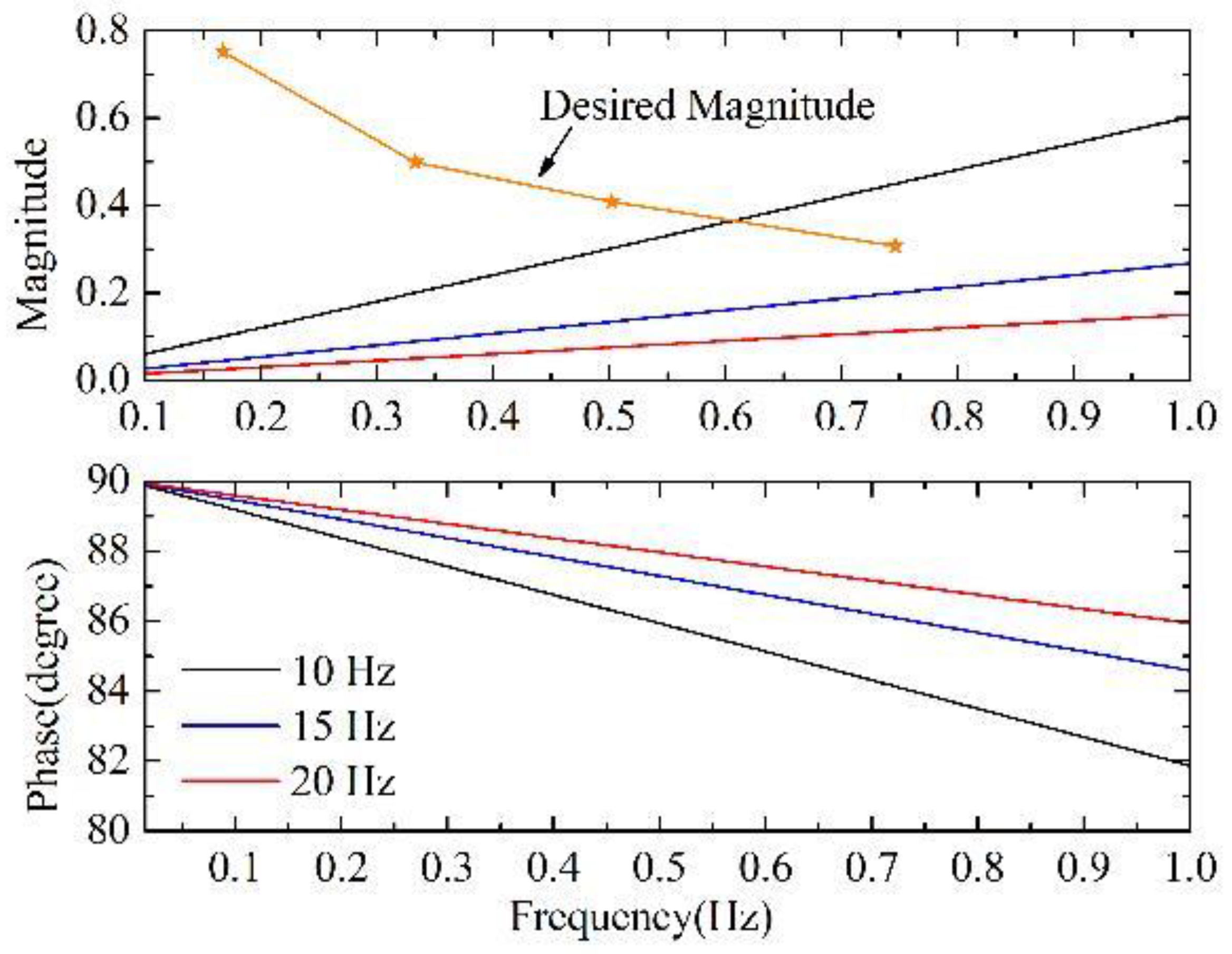
3.4. Design of Control Parameters

Laplace transform is applied to the DOBC in normal working mode to obtain the transfer function of the control input:
U ( s ) = 1 b ( s P d ( s ) + γ E ( s ) s + k 1 E ( s ) ) + f ( P ( s ) ) .
Assuming that the desired pressure remains constant, the leakage is relatively small compared to the inspiratory flow and the supply flow. The transfer function of control law can be simplified as C ( s ) = U ( s ) / E ( s ) = 1 b ( k 1 + γ s ) . Similarly, the transfer function of breath pressure could be obtained by Laplace transform, G ( s ) = b / s . According to the transfer function of control law and the plant, the influence of the inspiratory flow on the breath pressure can be expressed by the input sensitivity function:
S i ( s ) = G ( s ) 1 + G ( s ) C ( s ) = b s s 2 + k 1 s + γ .
Let the feedback gain and disturbance observer coefficient as k1 = 2ξωn, γ = ωn2. Then, the characteristic equation of the close-loop system can be expressed with the natural frequency ωn and damping coefficient ξ in the standard form of the second-order system. The magnitude-frequency characteristics of the input sensitivity function can be expressed as
M ( ω ) = | b j ω ω 2 + 2 ξ ω n s + ω n 2 | = b / ω n ( 2 ξ ) 2 + ( ω n ω ω ω n ) 2 .
It can be analyzed that the magnitude-frequency characteristic decreases monotonically with the increase of damping coefficient. When natural frequency ωn is greater than input disturbance frequency ω, the magnitude-frequency characteristic decreases monotonically with the increase of natural frequency, and increases monotonically with the increase of input disturbance frequency.
In order to make the respiratory resistance within the threshold in Table 1 it is necessary to limit the magnitude-frequency characteristics of the input sensitivity function under different input disturbance frequencies. Combined with the sinusoidal formula of inspiratory flow, the design objective of magnitude-frequency characteristics could be given by
W h e n   ω = 2 π f = 2 π 60 / N , M ( ω ) b j ω ω 2 + 2 ξ ω n s + ω n 2 .
According to the above equitation, the respiratory resistance threshold in Table 1 could be converted into the desired magnitude-frequency characteristic in Table 2.
Combined with the monotonically relationship analyzed above, it can be concluded from the Table 2 that if the magnitude-frequency characteristic of the input sensitivity function drops below 0.303 when the input disturbance frequency is 3/4 Hz, the control performance of DOBC could meet the inspiratory resistance threshold. The volume of breath chamber was set as 0.3 L, and the temperature was set as 293.15 K, so the coefficient b was calculated as 378.6 kPa/(g/s). The damping coefficient was selected as 0.707, and the natural frequencies were set as 10 Hz, 15 Hz, and 20 Hz, respectively. The Bode diagram of input sensitivity function was drawn in frequency range less than 1 Hz, as shown in Figure 3.
It can be seen from the magnitude-frequency characteristic diagram (upper panel) of the Bode diagram that when the natural frequency reaches 15 Hz, the magnitude-frequency characteristic can be maintained below the desired magnitude-frequency characteristic. At this time, the respiratory resistance control can theoretically achieve the control target. On the other hand, it can be seen from the phase-frequency characteristic diagram (lower panel) of Bode Diagram that the phase lag is between 80° and 90° at each natural frequency, which means that the response of breath pressure is ahead of the inspiratory flow in phase. Because of the sinusoidal wave of the inspiratory flow, the phase lead feature makes the peak of the inspiratory resistance appear at the beginning of the inhalation. Moreover, at the end of the inhalation, pressure error will become positive, which may lead to a higher expiratory resistance

4. Results and Discussion

4.1. Simulation Research

Simulation Researches were carried out to simulate the breath pressure during the whole breath process. Simulation parameters and conditions were set as follows. The natural frequency was set as 15 Hz and the damping coefficient was set as 0.707. Therefore, the state feedback gain k1 was calculated as 133, and disturbance observer coefficient was calculated as 8883. In order to simulate the discrete characteristics in the electronic control system, the sampling period of the controller Ts was set as 1 ms, and the time delay of system Td was set as 3 ms. White noise signal with the standard deviation of 0.005 kPa was added to the feedback loop to simulate the measurement noise of breath pressure signal.
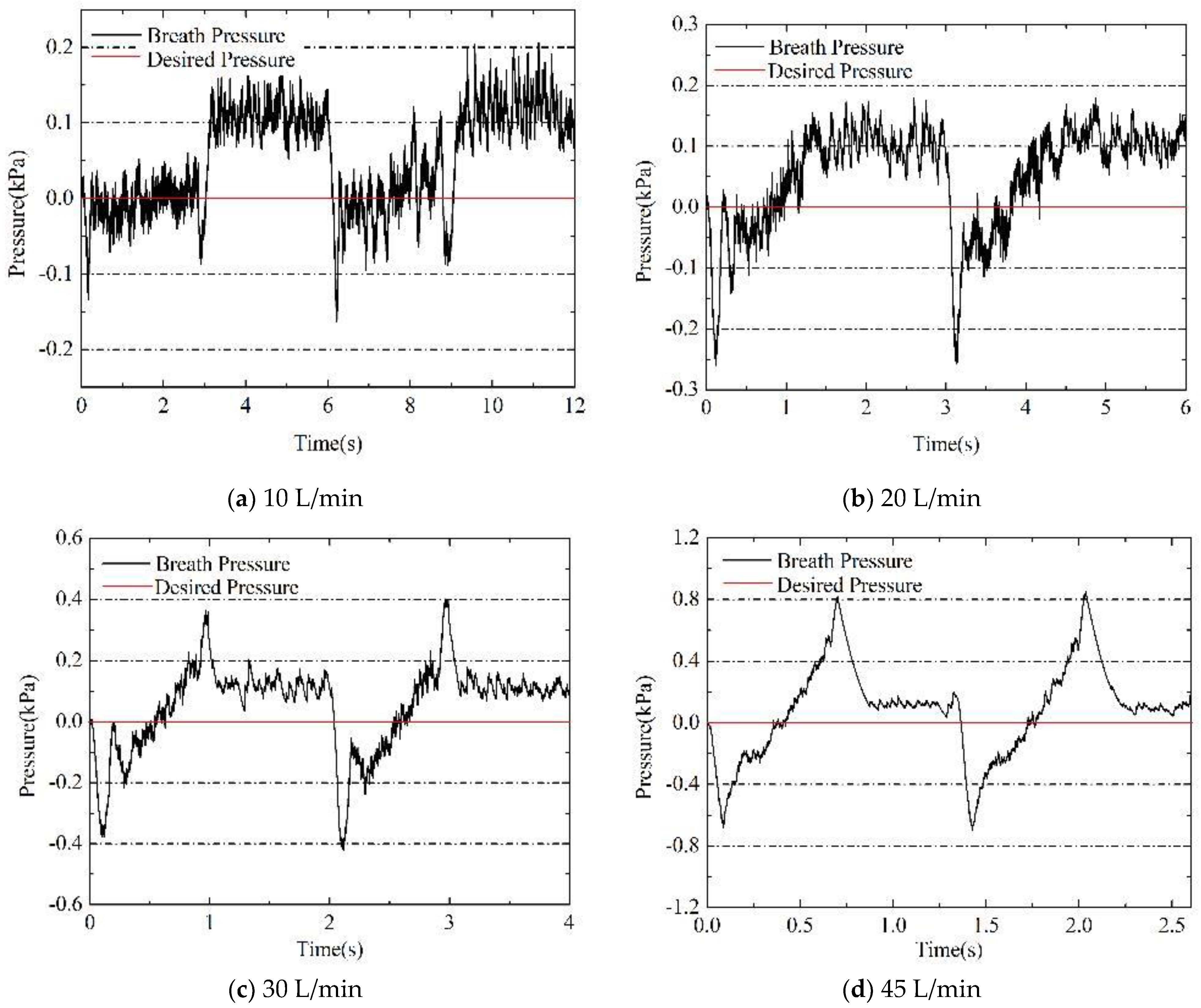
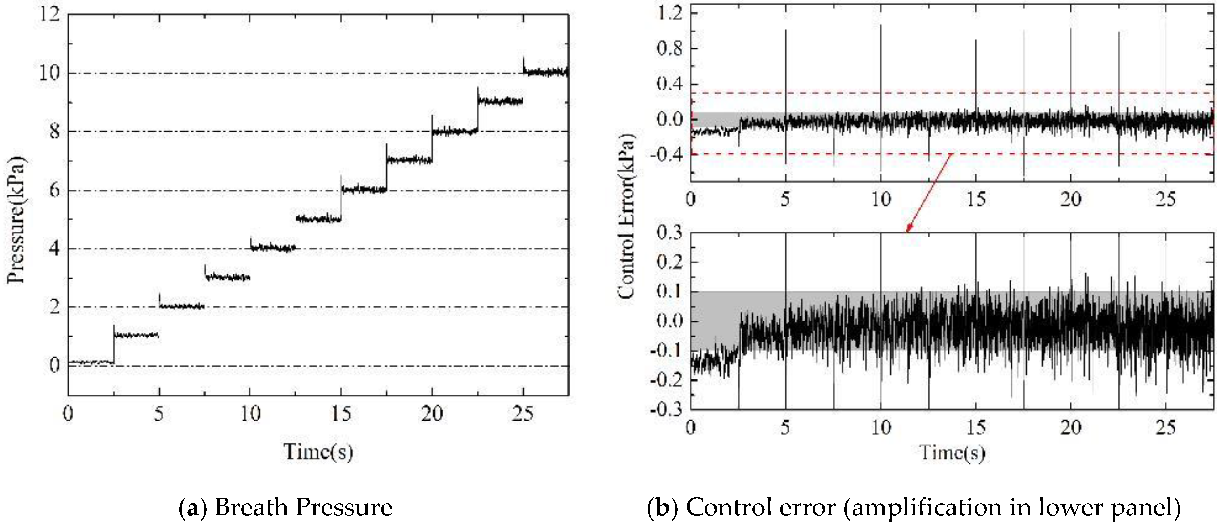
  • Simulation of normal breath
The desired pressure was set as 0 kPa to simulate the normal breath process. Figure 4 shows the dynamic curves of breath pressure under the control of DOBC for four different pulmonary ventilation rates of 10 L/min, 20 L/min, 30 L/min, and 45 L/min, respectively.
It can be seen from the simulation results that DOBC can provide appropriate supply flow according to the feedback breath pressure to meet the control target of respiratory resistance. In the stage of inhalation, when the pulmonary ventilation volume is small, the control process was affected significantly by the measurement noise, and the pressure fluctuates frequently near the desired pressure; when the pulmonary ventilation volume gets larger, the influence of measurement noise reduced gradually, and the phase response of breath pressure is basically consistent with the phase frequency characteristics in theoretical analysis, with the peak of inspiratory resistance at the initial of inhalation, and positive pressure at the end of inhalation. During exhalation, the breath pressure maintains a positive pressure of 0.1 kPa, result in a small expiratory resistance. This phenomenon is caused by the influence of measurement noise on control input of DOBC, making the supply flow fluctuate in a very small range.
  • Simulation of positive pressurization
The desired pressure was increased from 0 kPa to 10 kPa in a step process of 1 kPa to simulate the positive pressurization process. The curve of controlled breath pressure and the control error of DOBC were shown in Figure 5. In order to compare with the accuracy requirement, the control error was also amplified in part.
The simulation results show that the DOBC can reduce the control error in a very short time after the step of desired pressure signal and the overshoot could be limited to about 0.4 kPa. The control system has good ability of reference following and small overshoot characteristic. Furthermore, DOBC can achieve pressure control stably in the small breath chamber, and the steady-state error of control is basically maintained in the range of ±0.1 kPa, which basically meets the control accuracy requirement. According to the characteristics of the sensitivity function, the small input sensitivity function means that the complementary sensitivity function is close to 1. Therefore, the large control parameters in DOBC make close-loop system have good reference following performance and disturbance rejection at the same time. As a sacrifice, the negative effect of measurement noise was inevitably amplified. It can be deduced that the frequent fluctuation of control error is caused by measurement noise.

4.2. Experimental Research

The experimental platform of EOR is shown in Figure 6. The function of the host computer is to communicate with the FPGA controller, setting the desired pressure and record experimental data. Active servo lung can simulate breathing movements of a variety of pulmonary ventilation volume. The pressure of oxygen supply source is adjusted in the range of 0.08 MPa~0.6 MPa working pressure in advance. When the breath pressure is 10 kPa, the leakage flow rate of the relief hole has been calibrated as 0.062 g/s, which is equivalent to the volume flow rate of 3 L/min. The mask pressure sensor was added to evaluate the pilot’s breath comfort. The YM-6 pressurized oxygen mask was selected as the mask. The NI-9146 chassis with onboard FPGA chip is selected as the controller, and the acquisition and control functions of the controller are realized by NI-9205 and NI-9403, respectively. The operating frequency of the controller was set at 1 kHz. The control parameters of DOBC used in the experiment were set in accordance with the theory analysis, which has been used in the simulation. The flow control valve is driven by a high-precision, linear motion hybrid stepping motor. The flow curves under different inlet pressures are shown in Figure 7. Although the flow control valve has a hysteresis characteristic, the flow rate is generally linear with the output step. The output step of the flow control valve is adjusted according to the required flow calculated by DOBC, inlet pressure signal, and flow characteristic curve.
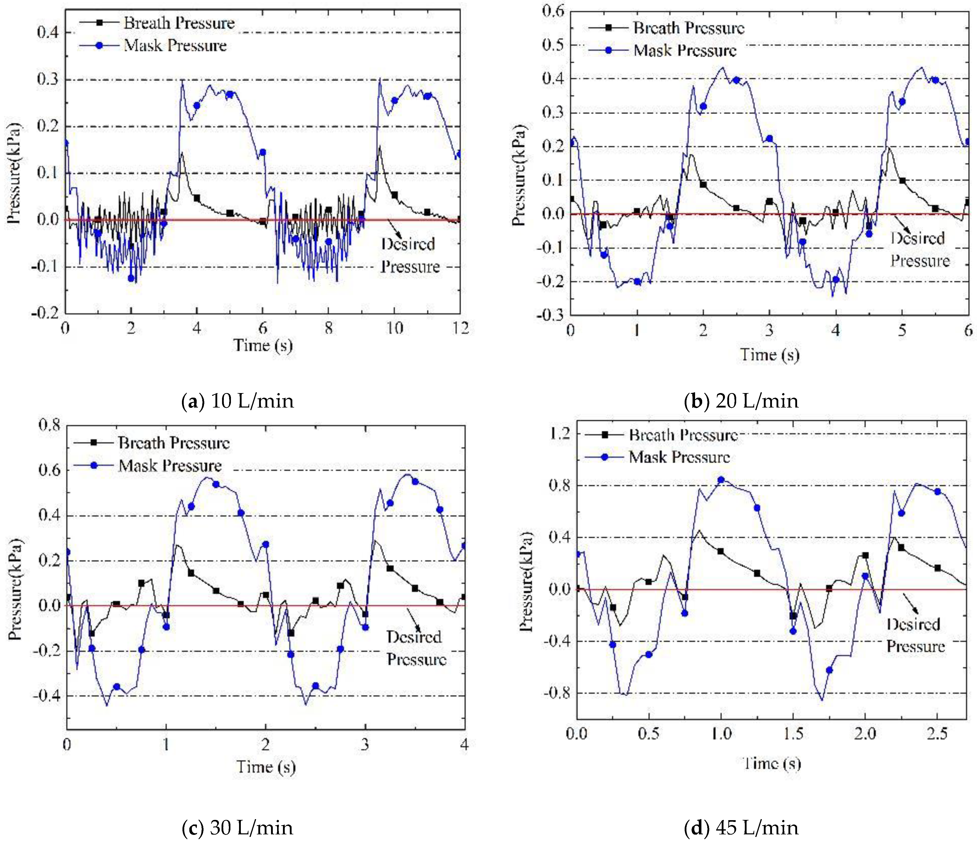
  • Experiment of normal breath
The normal breathing processes of four pulmonary ventilation volume were simulated by using the active servo lung. The recorded experimental results of breath pressure and mask pressure were shown in Figure 8. In addition, the maximum values of inspiratory resistance (IR) and expiratory resistance (ER) obtained from simulation and experiment were compared in Figure 9 with the thresholds in Table 1. It could be found that the control parameters of DOBC designed based on the frequency domain analysis could make the respiratory resistance under each pulmonary ventilation volume meet the threshold requirements of IR and ER. Combined with the mask pressure curve in Figure 8, the breath pressure was kept relatively stable and the pressure variation in mask was mainly affected by the flow resistance of the check valve on mask. This indicates that the pilot will have a good breath experience and not suffer from breathing fatigue.
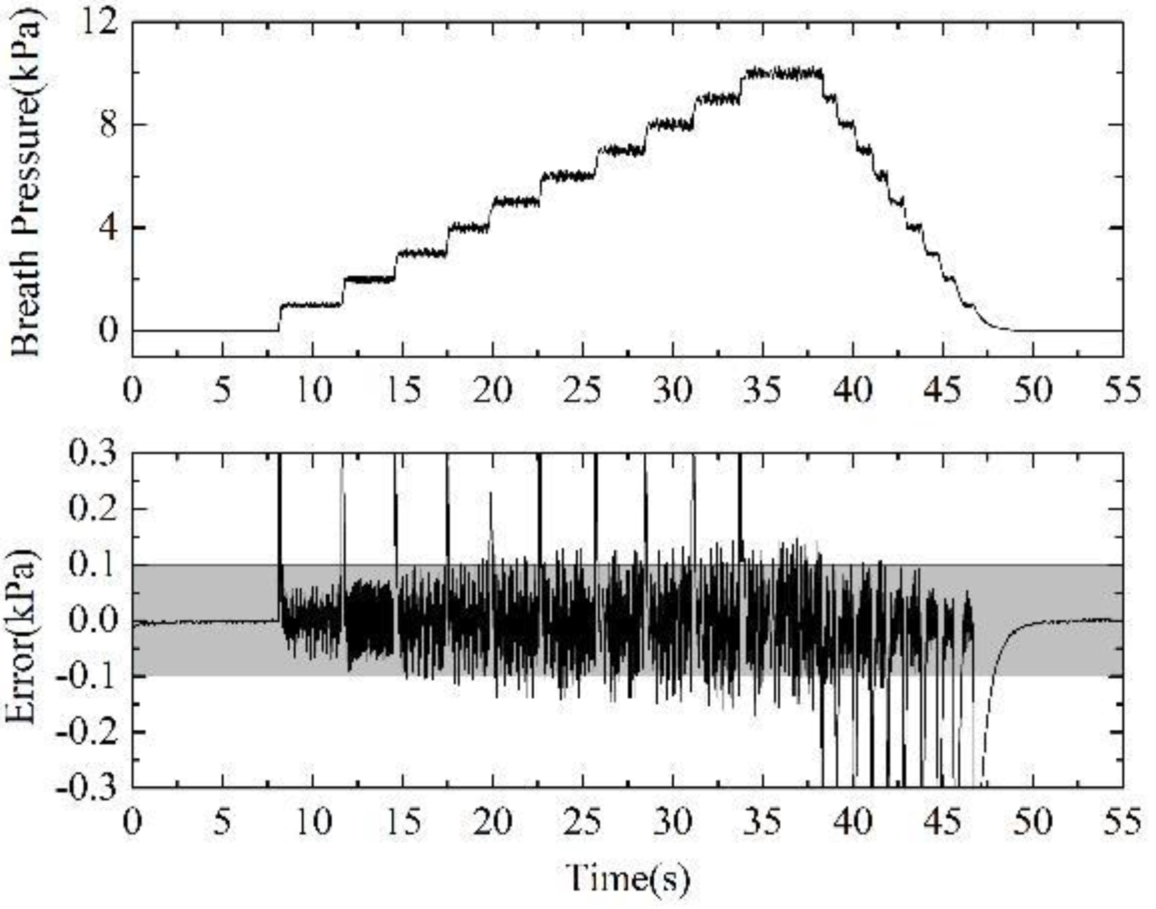
  • Experiment of positive pressurization
The desired pressure in experiment of positive pressurization process was set as same as the simulation condition. The curve of controlled breath pressure and the control error were shown in Figure 10.
The experimental results also verified the breath pressure control performance of DOBC in positive pressurization of the EOR. When the desired pressure was increased in the step of 1 kPa, the rise time of breath pressure was about 0.2 s, without significant overshoot. The steady-state error was kept within the control accuracy requirements of ±0.1 kPa, and only exceeded the requirements at few time points, which is acceptable in practical use. The continuous fluctuation of pressure was caused by the measurement noise amplified by large control parameters, and the reason has been explained in the discussion of simulation results.
Comparing the simulation results with the experimental results, it was found that the simulation research can nearly reflect the actual DOBC control performance. The experimental results are slightly better than the simulation results. The error between simulation and experiment might come from model errors and parameter uncertainties. First, the actual physical processes were simplified in mathematical model. Furthermore, the simulated white noise signal could not be identical to the measurement noise in experiment. Secondly, although some physical parameters can be measured directly, some other parameters might not be set accurately, such as standard deviation of noise and delay time of system. In addition, hysteresis characteristics and the fitting of linear gain of flow control valve will also cause errors between simulation and experiment. Overall, the simulation accuracy is acceptable and the mathematical model could be use in further study about the EOR.

5. Conclusions and Perspectives

In this paper, the mathematical model of the electronic oxygen regulator was established, and the main factors affecting the breath pressure control were analyzed. Based on the Lyapunov stability and backstepping design method, the DOBC with better stability and robustness has been designed, which can compensate the model error and the parameter uncertainty in the system. To avoid integral saturation, the clapping anti-windup mechanism was designed and adopted. The influence of the inspiratory flow on the breath pressure was described by the input sensitivity function, and the frequency domain analysis was applied to design the control parameter of DOBC for the first time, which could provide important theoretical guidance for the design of controller and control parameters of EOR.
The study shows that when the natural frequency of the close-loop control system reaches 15 Hz, the inspiratory resistance can meet the threshold requirements in theory. Through simulation and experimental researches, performance of the respiratory resistance and positive pressurization of the EOR under DOBC were obtained, which meets the physiological and protective requirements. It can be concluded that the application of DOBC in breath pressure control of EOR was reasonable and effective. However, it was found that although larger control parameters could reduce the respiratory resistance range, it will inevitably lead to the amplification of measurement noise, so that the control steady-state error cannot be completely eliminated and the pressure fluctuate continually. Further studies will be conducted to solve the contradiction.
Although there are certain errors between simulation and experiment, the main trend and approximate range of breath pressure can still be estimated by simulation, which proved the validity of the proposed model and provides a basis for further research on breath pressure control of EOR through simulation technology.
In the future study, the design method of control parameter based on frequency domain analysis will be applied to some other control laws. Then, we could compare the advantages and disadvantages of various control methods in the breath pressure control of EOR fairly. It is also possible to conduct physiological experiments in low-pressure-chamber to simulate performance of EOR during flight more realistically.

Author Contributions

Conceptualization, R.P., G.L., Z.S. and Y.Z.; methodology and investigation, R.P., G.L., Y.Z. and X.Y.; formal analysis, R.P., Y.Z. and X.Y.; software, R.P.; validation and resources, R.P. and Z.S.; writing—original draft preparation, R.P.; writing—review and editing, R.P. and Y.Z.; supervision and project administration, G.L. All authors have read and agreed to the published version of the manuscript.

Funding

This research received no external funding.

Institutional Review Board Statement

Not applicable.

Informed Consent Statement

Not applicable.

Data Availability Statement

Not applicable.

Conflicts of Interest

The authors declare no conflict of interest.

References

  1. Xiao, H.J. Application Physiology of Aircraft Oxygen Protective Equipment; Military Medical Science Press: Beijing, China, 2005; pp. 34–46. (In Chinese) [Google Scholar]
  2. Rainford, D.J.; Gradwell, D.P. Ernsting’s Aviation Medicine, 4th ed.; Oxford University Press: London, UK, 2006; pp. 105–127. [Google Scholar]
  3. Yan, S.H.; Yixuan, W.A.; Maolin, C.A.; Zhang, B.; Jian, Z.H. An aviation oxygen supply system based on a mechanical ventilation model. Chin. J. Aeronaut. 2018, 31, 197–204. [Google Scholar] [CrossRef]
  4. Ackles, K.N.; Porlier JA, G.; Holness, D.E. Protection against the physiological effects of positive pressure breathing. Aviat. Space Environ. Med. 1978, 49, 753–758. [Google Scholar] [PubMed]
  5. Lauritzsen, L.P.; Pfitzner, J. Pressure breathing in fighter aircraft for G accelerations and loss of cabin pressurization at altitude—A brief review. J. Can. Danesthésie 2003, 50, 415. [Google Scholar] [CrossRef] [Green Version]
  6. Pan, R.; Lin, G.P.; Zeng, Y.; Yang, X.; Shi, Z.G. Modeling and Simulation of Diaphragm Oxygen Regulator Pressure Control system. In Proceedings of the 2019 IEEE 10th International Conference on Mechanical and Aerospace Engineering (ICMAE), Brussels, Belgium, 22–25 July 2019; pp. 6–10. [Google Scholar] [CrossRef]
  7. Beaumont, M.; Lejeune, D.; Isabey, D.; Marotte, H.; Harf, A.; Lofaso, F. Positive pressure generation by pneumatic and electronic O2 regulators: A bench experimental evaluation. Aviat. Space Environ. Med. 1999, 70, 812–818. [Google Scholar] [CrossRef] [PubMed] [Green Version]
  8. Xiao, H.J. Molecular sieve oxygen systems on French military aircraft. Aeronaut. Astronaut. 1996, 1, 38–42. (In Chinese) [Google Scholar]
  9. Siska, W.D., Jr.; Collins, R.; Carleton Technologies Inc. Electromechanical Oxygen Valve and Regulator. United States Patent US 7677529 B2, 10 March 2010. [Google Scholar]
  10. Frampton, R.; B/E Intellectual Property. Electromechanical Regulator with Primary and Backup Modes of Operation for Regulating Passenger Oxygen. United States Patent US 7604019 B2, 20 October 2010. [Google Scholar]
  11. Yu, Z.; Zhao, J. Simulation of pressurized oxygen supply performance of air oxygen supply system based on Simulink. Microcomput. Appl. 2010, 31, 1–6. (In Chinese) [Google Scholar]
  12. Yu, Z.; Bing, S.; Weidong, W.; Guiping, L. Simulation and optimization of a new pulmonary mechanism in electronic oxygen regulator. In Proceedings of the 2016 IEEE International Conference on Aircraft Utility Systems (AUS), Beijing, China, 10–12 October 2016; pp. 719–722. [Google Scholar] [CrossRef]
  13. Yu, X.; Sun, B.; Lin, G.; Wang, H. Application of ATmega128 microcontroller in electronic oxygen regulator. Micro-Comput. Appl. 2009, 12, 50–56. (In Chinese) [Google Scholar]
  14. Sun, C.; Cai, Y.; Long, H. Research on stepping motor fuzzy control technology application in the aircraft electronic oxygen regulator. Meas. Control Technol. 2013, 4, 82–87. (In Chinese) [Google Scholar]
  15. Li, X.; Lin, G.; Zeng, Y.; Wu, F. Design of electronic oxygen regulator PID control system based on LabVIEW. Comput. Meas. Control. 2016, 3, 80–83. (In Chinese) [Google Scholar]
  16. Yuxin, J.; Qinglin, S.; Zengqiang, C.; Sanpeng, D. Modeling and simulation of an electronic oxygen regulator based on generalized predictive control algorithm. In Proceedings of the 34th China Control Conference (CCC), Hangzhou, China, 28–30 July 2015; pp. 4067–4072. [Google Scholar] [CrossRef]
  17. Jiang, Y.; Sun, Q.; Zhang, X.; Chen, Z. Pressure Regulation for Oxygen Mask Based on Active Disturbance Rejection Control. IEEE Trans. Ind. Electron. 2017, 6402–6411. [Google Scholar] [CrossRef]
  18. Jiang, Y.; Sun, Q.; Tan, P.; Chen, Z. Modeling and Simulation of an Electronic Oxygen Regulator Based on All-Coefficient Adaptive Control. ASME J. Dyn. Sys. Meas. Control 2016, 138, 081010. [Google Scholar] [CrossRef]
  19. Amare, N.D.; Kim, D.H.; Yang, S.J.; Son, Y.I. Boundary Conditions for Transient and Robust Performance of a Reduced-Order Model-Based State Feedback Controller with PI Observer. Energies 2021, 14, 2881. [Google Scholar] [CrossRef]
  20. Gao, N.; Lin, X.; Wu, W.; Blaabjerg, F. Grid Current Feedback Active Damping Control Based on Disturbance Observer for Battery Energy Storage Power Conversion System with LCL Filter. Energies 2021, 14, 1482. [Google Scholar] [CrossRef]
  21. Baran, J.; Jąderko, A. An MPPT Control of a PMSG-Based WECS with Disturbance Compensation and Wind Speed Estimation. Energies 2020, 13, 6344. [Google Scholar] [CrossRef]
  22. Rui, P.A.; Guiping, L.I.; Zhigao, S.H.; Yu, Z.E.; Xue, Y.A. Analysis and control optimization of positive pressure fluctuation in electromechanical oxygen regulator. Chin. J. Aeronaut. 2021, 34, 205–213. [Google Scholar] [CrossRef]
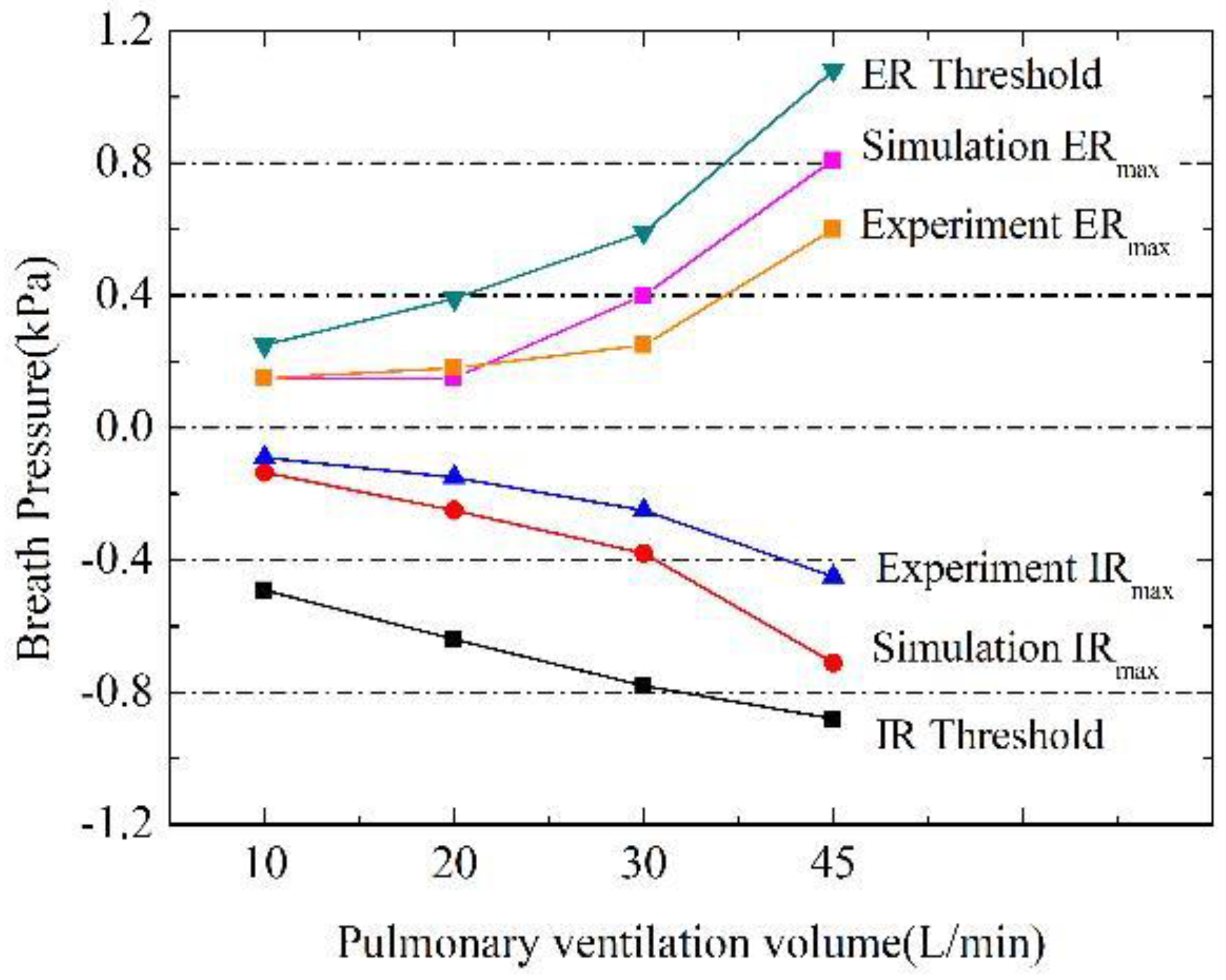
Figure 1. The structure and working principle of aviation oxygen system.
Energies 14 05189 g001
Figure 2. The block diagram of DOBC with clamping anti-windup mechanism.
Energies 14 05189 g002
Figure 3. The Bode diagram of input sensitivity function, upper panel: magnitude-frequency characteristic, lower panel: phase-frequency characteristic.
Energies 14 05189 g003
Figure 4. Simulation results of breath pressure during breath under different pulmonary ventilation volume, (a) 10 L/min, (b) 20 L/min, (c) 30 L/min, and (d) 45 L/min.
Energies 14 05189 g004
Figure 5. Simulation results of breath pressure and control error under DOBC during positive pressurization process: (a) breath pressure curve; (b) control error curve and its amplification in lower panel.
Energies 14 05189 g005
Figure 6. Experimental platform.
Energies 14 05189 g006
Figure 7. Characteristics of flow control valve under different inlet pressure.
Energies 14 05189 g007
Figure 8. Experiment results of breath pressure during breath under different pulmonary ventilation volume, (a) 10 L/min, (b) 20 L/min, (c) 30 L/min, and (d) 45 L/min.
Energies 14 05189 g008
Figure 9. Comparison of respiratory resistance between the threshold values in Table 1, simulation results, and experiment results.
Energies 14 05189 g009
Figure 10. Experiment results of breath pressure under DOBC during positive pressurization process in upper panel and control error in lower panel.
Energies 14 05189 g010
Table 1. Respiratory resistance threshold under different pulmonary ventilation volumes.
Pulmonary Ventilation Volume (L/min)Inspiratory Resistance (kPa)Expiratory Resistance (kPa)
10≤0.49≤0.25
20≤0.64≤0.39
30≤0.78≤0.59
45≤0.88≤1.08
Table 2. Desired magnitude-frequency characteristics of the input sensitivity function.
Pulmonary Ventilation Volume (L/min)Input Disturbance Frequency (Hz)Maximum of Inspiratory Flow (g/s)Inspiratory Resistance
Threshold (kPa)
Desired Magnitude-Frequency Characteristics
101/60.65≤0.49≤0.754
201/31.3≤0.64≤0.492
301/21.95≤0.78≤0.4
453/42.9≤0.88≤0.303
Publisher’s Note: MDPI stays neutral with regard to jurisdictional claims in published maps and institutional affiliations.

