Review

A Review of Modeling and Diagnostic Techniques for Eccentricity Fault in Electric Machines

1
Key Laboratory of Vehicle Transmission, China North Vehicle Research Institute, Beijing 100072, China
2
Department of Electrical Engineering, Tsinghua University, Beijing 100084, China
3
Department of Energy Technology, Aalborg University, DK-9220 Aalborg East, Denmark
4
College of Electrical Engineering, Zhejiang University, Hangzhou 310027, China
*
Author to whom correspondence should be addressed.
Energies 2021, 14(14), 4296; https://doi.org/10.3390/en14144296
Submission received: 18 May 2021 / Revised: 12 July 2021 / Accepted: 13 July 2021 / Published: 16 July 2021

Abstract

:
Research on the modeling and fault diagnosis of rotor eccentricities has been conducted during the past two decades. A variety of diagnostic theories and methods have been proposed based on different mechanisms, and there are reviews following either one type of electric machines or one type of eccentricity. Nonetheless, the research routes of modeling and diagnosis are common, regardless of machine or eccentricity types. This article tends to review all the possible modeling and diagnostic approaches for all common types of electric machines with eccentricities and provide suggestions on future research roadmap. The paper indicates that a reliable low-cost non-intrusive real-time online visualized diagnostic method is the trend. Observer-based diagnostic strategies are thought promising for the continued research.

1. Introduction

The diagnostic approaches toward predictive maintenance for rotating electric machines have been developed for decades. They provide early detection and severity evaluation with ease, saving time and labor costs [1,2,3]. A good diagnostic approach should also provide out-of-service margin, which helps to make full use of service life and make maintenance schedules.
In this area, the diagnosis for rotor eccentricity has attracted attention due to its catastrophic consequences. In general, there is a tolerable inherent eccentricity degree due to limited accuracy of fabrication and assembly. The permissible eccentricity could be exacerbated due to stresses or faults, such as misalignment and bearing wear. A lateral injure of bearing ball could cause shaft incline and rotor eccentricity occurs. Longtime misalignment would cause shaft bent and rotor eccentricity occurs. The aggravated eccentricity causes unbalanced magnetic pull, increased cogging torque, excessive vibration, and rotor temperature increase [4]. As the direction of unbalanced magnetic pull is roughly consistent with the direction of eccentricity, the rotor is gradually dragged to a more eccentric position. This positive feedback eventually evolves to a rotor stator rub, which harms lamination and generates sparks. Besides, an inverter-driven permanent magnet synchronous machine (PMSM) prototype with severe eccentricity could cause serious torque oscillations and inverter failures. Nonetheless, these hazards can be avoided by applying advanced diagnostic approaches [5].
Various diagnostic methods have emerged so far, and there are reviews regarding the diagnosis of eccentricity [6,7,8,9]. These articles discuss either one type of rotary machines or eccentricity. On the other hand, other reviews on general topics of diagnostics cannot give full discussion on eccentricities. While in this paper, all the possible modeling and diagnostic approaches for rotor eccentricities in general types of electric machines are reviewed. It is held that there are common research routes in the eccentricity modeling and diagnostics for any type of machines. Therefore, the paper is organized in a general frame and the most representative diagnostic strategies are reviewed. Suggestions for future research from the perspective of electrical engineering are given.
The paper is organized as follows. In Section 2, a brief review of the rotor eccentricities is presented. In Section 3, modeling techniques of electric machines with eccentricity faults are reviewed. In Section 4 and Section 5, the eccentricity diagnostic approaches are analyzed based on their most prominent features. The approaches are classified into model-based, and signal- and data-based methods, which will be dealt with separately. The challenges on the distinction between the eccentricity and other similar faults are discussed in Section 6. The trend of diagnostic approaches for eccentricities is further discussed in Section 7. The conclusion is presented in Section 8.

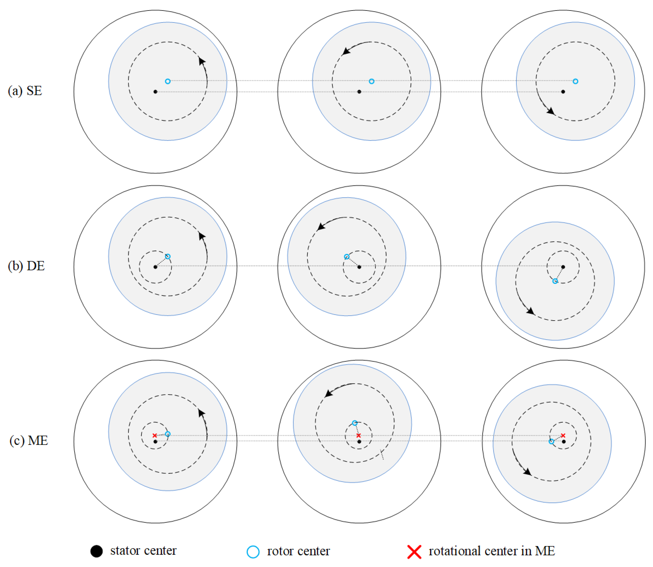
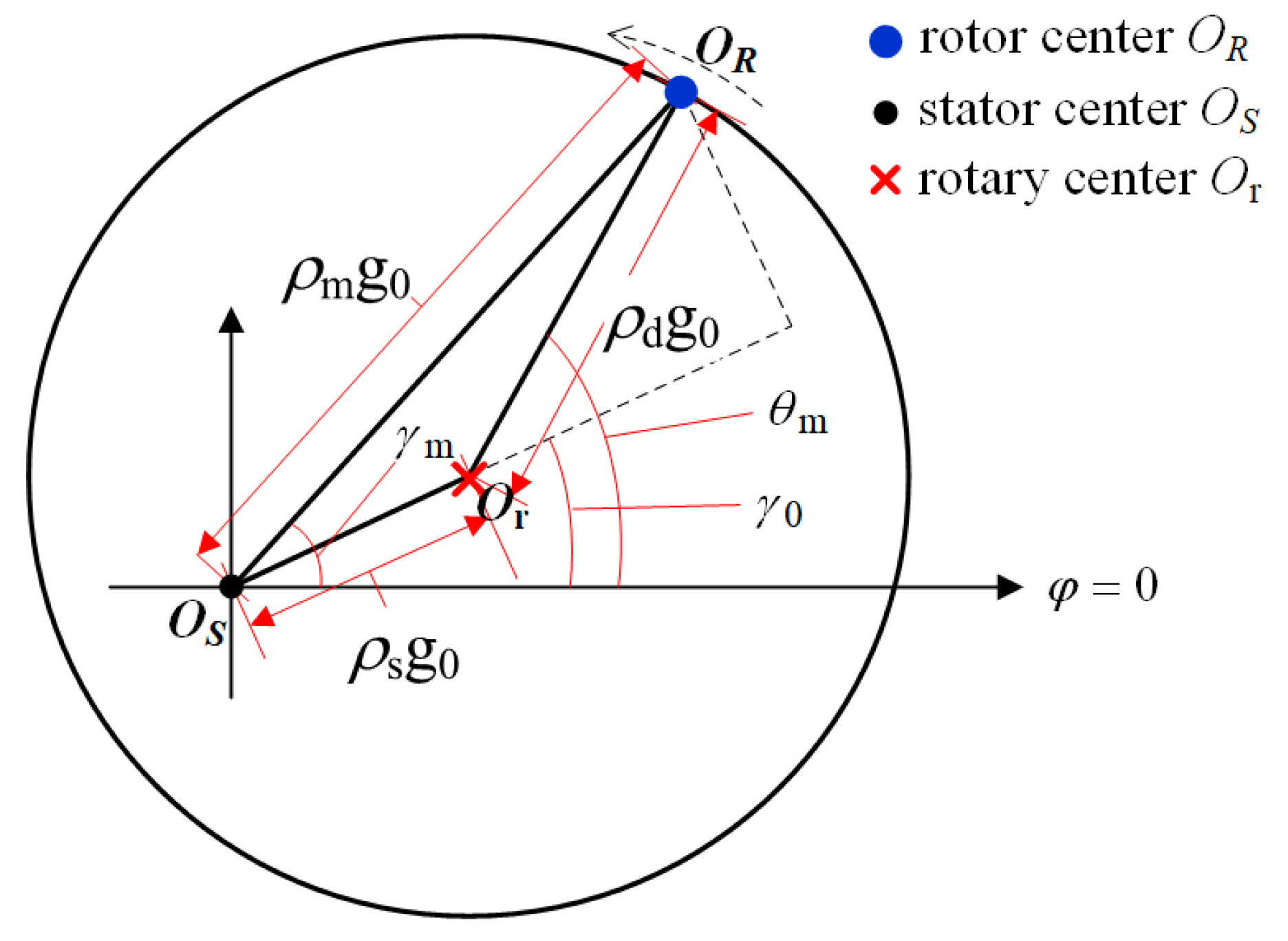
2. Rotor Eccentricity

In the literature, the rotor eccentricity is idealized as static eccentricity (SE), dynamic eccentricity (DE), or mixed eccentricity (ME), as shown in Figure 1 [10,11]. The SE indicates that the rotor and the stator centers do not coincide, and the rotor revolves the rotor center. The DE indicates that the rotor and the stator centers do not coincide, and the rotor revolves both the stator and the rotor centers. The ME contains both the SE and the DE, and in which case the rotor revolves a third center other than the stator and the rotor centers. The definitions of SE degree ρs, DE degree ρd, and ME degree ρm are depicted in Figure 2, where g0 represents the air-gap length. It is indicated that if ρs equals ρd, then the rotor center trajectory will pass through the stator center. In [12], an axial inclined or a bent rotor is modeled in segments to analyze the air-gap flux and unbalanced magnetic pull. Nonetheless, the 2-D SE, DE, and ME models are enough for study.
According to the permeance formula Λ = g·S/μ and the definition of inductance L = N1N2/Λ, where g is the air-gap length, S is the area, μ is the permeability, N1 and N2 are the number of turns, the asymmetric air gap distribution affects the inductances by changing g and μ, and further the distorted inductances cause fault harmonics in the machine currents. Therefore, the diagnostics have been proposed based either on exposed (current/voltage/power) performance or on internal (inductance) distortion.
The low-frequency fault frequencies of ME in line currents are depicted as [13]
f ecc = υ f s ± k f r
where fs is the power supply frequency, fr is the mechanical rotational frequency, ν is the principal harmonic order of stator currents, and k is a positive integer.
Specifically, for an IM with rotor slot harmonics, the high-frequency band fault frequencies of the eccentricity faults in currents are depicted by [13]
f h = ( k Z 2 ± n d ) f r ± υ f s
where Z2 is the number of rotor slots. For the SE, nd is 0, while for the DE, nd is a positive integer. Note that fh with nd = 0 are the rotor slot harmonic frequencies, therefore the SE fault causes a rise in the amplitude of rotor slot harmonics. For the pure SE or pure DE, it has been also found that the prerequisite of Equation (2) is that Z2 and p should satisfy Z2 = 2p (3(m ± q) ± r) for a balanced three phase winding, where p is the number of pole pairs, m ± qN+, and r = 0 or 1 [14]. Nonetheless, the ME fault is most considered in practice. Figure 2 shows the calculation model of ME degree.

3. Modeling of Machines with Eccentricities

An accurate model with configurable eccentricity type and degree can be used to predict the potential performance of a diagnostic strategy [15]. The finite element method (FEM), the analytical method, the magnetic equivalent circuit (MEC) method, and the modified winding function approach (MWFA) have been reported.
The FEM precisely simulates the magnetic field distribution and parameter variations of a faulty machine provided that the physical properties and geometrical dimensions are given. The simulated inductances of an interior PMSM under the ME condition is provided in [16] by using FEM. However, as the ME (and also the DE) has time-varying air gap length, it requires full time-step FEM, which is slow compared with static FEM which can be used for the SE. The joint simulation of FEM and digital control demands excessive computation [17,18]. Furthermore, the FEM cannot provide analytical mathematic relations between concerned variables and eccentricity degree, especially in the case of ME. Therefore, the FEM has been often utilized to verify the other methods.
The analytical methods include subdomain methods, perturbation methods, superposition methods, field reconstruction methods, and so forth [19,20,21,22,23,24,25]. Although the computation burden of the analytical methods is less than that of the FEM, the literature shows that the analytical methods have difficulty in dealing with the ME due to the continuous movement of the minimum air gap location. Therefore, the analytical methods are mostly used to calculate the cogging torque, air-gap field distribution, and UMP for a surface-mounted PMSM or an induction machine (IM) with SE or DE. The analytical method is seldom utilized to verify diagnostic strategies for inverter-driven eccentric machines.
The MEC and MWFA use magnetic circuit to describe electric machines. Both can be implemented in the MATLAB®/Simulink® (MathWorks, Natick, MA, USA) combined with a converter model, and thus the performance of a converter-based diagnostic strategy can be easily predicted and evaluated. As a lumped parameter method, the MEC uses permeance network to describe machine structure. An eccentric salient pole synchronous machine model based on MEC has been developed in [26]. A 3-D MEC model has been proposed to calculate the winding inductances of an eccentric IM in [27]. The MEC method can retain more structural details than the analytical method, yet its computation could be more intensive. The MWFA, which was proposed by Toliyat and developed by Faiz et al., is the extension of winding function theory for the eccentricity modeling of electric machinery [28,29]. As the model accuracy of MWFA is limited due to its series approximation of inverse air-gap function, a unified winding function approach has been further proposed to overcome this drawback in [16,30], and the effect of slotting and saturated teeth reluctance have been further considered in [31]. Recently a simplified MWFA model for IM with ME has been presented to reduce the computational effort caused by rotor bars [32]. In a word, the MWFA assumes superposition in taking saturation and slotting effects into account, which depends on machine type and is challenging. The MWFA is not comparable to the MEC method in retaining the physical geometrical details, while the computation burden of MWFA can be less. The simulation accuracy of MEC and MWFA could be the same if only the air-gap permeance is considered in the modeling. Moreover, the MWFA is easier to provide analytical solutions of inductance matrices especially in the case of ME [33]. Table 1 compares the characteristics of these modeling approaches qualitatively.

4. Model-Based Diagnosis

It is held herein that if a diagnostic strategy is based on the analysis of machine system model and related theories rather than the direct adoption of well-known eccentricity fault signatures like Equations (1) and (2), then it is classified as a model-based approach. The model-based approaches are superior to merely utilizing well-known eccentricity fault signatures because Equations (1) and (2) can confuse the eccentricity fault with other faults that have similar sideband patterns, which will be discussed in Section 6.
Model-based methods have been proposed in the last two decades. They are herein divided into simulation model analysis, MMF-permeance analysis, instantaneous power analysis, coordinate transform, auxiliary voltage injection, sensor-based and observer-based approaches, etc.

4.1. Simulation Model Analysis

The diagnostic approach based on simulation model analysis is to establish a faulty model for a real target prototype and predict the behavior based on the appearing fault signatures in simulation. The signatures are handled as the diagnostic criteria for the prototype machine.
For mains-fed and voltage source converter-driven machines, the winding currents under fault condition are unknown and different from those under healthy condition. Therefore, the supply input of simulation model should be configured as voltage source. For instance, time-step FEM, MWFA, and MEC model with applied voltage source have been developed to simulate currents of healthy and faulty machines [34,35,36]. Motor current signature analysis (MCSA) can be selected to analyze the simulated currents and spectral components of significant amplitude increase under SE, DE, and ME can be taken as fault indices [37,38]. In this way, the amplitudes of (1 ± (2k − 1)/p) fs and fs ± fr are selected as SE and ME indices, respectively, for a surface-mounted PMSM in [39]. The amplitude of 2fs is selected to detect SE fault for a salient pole synchronous generator [40]. For IMs, the amplitudes of fh (k = 1, ν = 1) and fs ± kfr are considered to discriminate SE, DE, and ME [41]. However, an important conclusion is arrived through MWFA model analysis that if an axial inclined rotor of IM with SE is symmetrical about the midpoint, then there are no SE frequencies in fh [42]. It can be concluded that simulation model-based MCSA relies on machine type and physical properties, indicating that the frequency indices of a machine could become invalid if design sheets are adjusted. Therefore, other simulation model-based approaches have been proposed as well. In [43], an exact MWFA model is developed for an IM prototype, and particle swarm optimization is introduced to correct the SE and DE degrees of model until minimum fitting function value is reached. The eccentricity type and severity are determined in this way. Stator inductance fluctuation is proposed in [44] as an eccentricity index for IM based on MWFA model.
The FEM model analysis is an effective tool for eccentricity diagnosis of the switched reluctance machine (SRM). The current source is applied to the SRM model for current chopping control mode and the voltage source is applied to the SRM model for single-pulse control mode. It has been found in simulation that the amplitudes of mutual induced voltages of idle phases increase with the eccentricity degree. Then the mutual induced voltage is proposed in [45] as the fault index for a 4-phase 8/6 SRM.
The simulation model analysis has also been applied to resolver position sensors which is assembled along with the machine because the resolver can reflect the eccentricity in the electric machine. In [46], an MWFA model of resolver under SE and DE has been developed and fault indices are proposed based on the regular resolver signals. The eccentricity in the machine is detected indirectly. Its advantage is the low complexity of eccentric resolver model because the resolver operates in linear zone and its structure is simple.

4.2. MMF-Permeance Analysis

The MMF-permeance analysis has been developed to predict fault frequencies of eccentricity [47,48,49,50,51]. Its theory is to expand F1/Λ into series expansion, where F1 is the time-space function of stator MMF and Λ is the time-space function of air-gap permeance. The merit of this method is that the effects of slotting and magnetic saturation can be easily considered with concise derivation. Nonetheless, as it cannot provide rigid quantitative results, the method is often used to provide theoretical basis for frequency distribution.

4.3. Instantaneous Power Analysis

The eccentricity of IM has been diagnosed by instantaneous power signature analysis (IPSA) in [52]. However, the fault indices of IPSA are found to be affected by motor load and control mode [53]. Therefore, it is hard to claim that the IPSA is better than MCSA. In [54], the apparent power signature analysis has been proposed to diagnose the eccentricity fault. In [55], the amplitude of fr frequency component of instantaneous reactive power spectrum has been used to diagnose the ME for a doubly-fed induction generator. Experiments show that the sensitivity of fr amplitude is twice that of MCSA. The instantaneous power analysis is not a widely adopted means in literature.

4.4. Coordinate Transform

The usage of Clarke and Park transforms is a general measure for motor diagnosis. (It should be reminded herein that the Clarke and the Park transforms are confused in some literature.) The Clarke transform of stator currents should be a circle and the shape deforms in the case of unbalance faults. Therefore, the Clarke transform of stator voltages and currents have once been used for diagnosis. However, it fails to separate the fault types. Therefore, it is often combined with the other methods. The Park transform has been often utilized to diagnose broken rotor bar (BRB) instead of eccentricity. This is because the BRB frequency is 2k times the slip frequency and can be submerged by spectral leakage at light load, but this is not an issue for the eccentricity detection [56]. Nonetheless, the SE fault has been detected based on the shift direction of Vd and Vq [57].
In addition, zero or negative sequence components have been used to diagnose SE for the IM. As stated earlier, the SE can be diagnosed by Equation (2) only if p and Z2 have a particular relation. Otherwise, new solutions have to be explored. In [58], slot harmonic components in zero-sequence current are proposed to solve this issue. In [59], the fundamental negative sequence of q-axis current is used to diagnose the SE.
An ingenious approach has been proposed in [60,61]. The stator winding of a synchronous generator is customized as parallel-pole-phase group structure. Each branch is equipped with a current sensor. If the total number of parallel branches is R, then this 2p-pole 3-phase generator is equivalent to a 2-pole R-phase machine. The R-phase currents are further turned into 0th ~ (R − 1)th complex sequence components by symmetrical components transform. Two generalized zero-sequence components and (R/2 − 1) pairs of complex conjugate sequence components are obtained. Only the first R/2 sequences are considered due to the conjugate relation. The pth order attributes to the fundamental supply fs, and the (p ± 1)th order attributes to the eccentricity. Then, the eccentricity component and the fundamental supply component are finally decoupled in time domain. 2-D visualization of eccentricity components using LabVIEW® (National Instruments, Austin, TX, USA) is shown in Figure 3. However, the main drawbacks of this approach are that it requires R sensors and the winding structure has to be redesigned, indicating that the hardware cost increases, and the reliability decreases, and that the designated winding distribution limits its application.

4.5. Auxiliary Voltage Injection

Diagnosis based on auxiliary voltage signals has attracted much attention recently. Different injection patterns have been proposed to obtain equivalent inductance or impedance, which is used to detect eccentricities [62,63,64,65]. In most cases, the injection patterns are generated by inherent converter of the driving system, which do not need additional hardware. In [62], the rotor of an IM is kept halted and a low-amplitude rotational square-wave pulsating voltage is injected by converter. The curve of zigzag leakage inductance (or impedance) along the mechanical circle is then calculated for eccentricity detection. In [63], on the contrary, the direction of the pulsating voltage is fixed while the rotor of an IM is manually rotated. The pulsating voltage is applied between any two phases with an AC power supply. Despite the fact that the method in [63] requires manual operation, its accuracy is higher than that in [58]. The injection pattern is further modified in [64], where the rotor of the IM is halted, and a low-frequency square-wave pulsating voltage with an increasing DC bias is injected in a fixed direction by converter. The curve of the calculated differential inductance with resulted DC current values is drawn. The knee point on the curve is used to diagnose eccentricity. The method in [64] is further extended onto a PMSM [65]. The DC bias is no more needed owing to the existence of PM, and the equivalent differential d-axis inductance is proposed as the eccentricity fault index of PMSM. The indices relating to the differential d-axis inductance further evolves in [66], where the d-axis axis saturation current and the height of lump of incremental inductance curve are used to detect the SE fault of PMSM. The imperfection of the aforesaid approaches is that they are implemented offline and cannot provide online diagnosis.
Moreover, research efforts are also dedicated to realizing real-time eccentricity visualization based on auxiliary injection. The trajectory of transient current change vector has been proposed using high-frequency pulsating voltage [67,68,69]. It is a real-time visualized offline approach, while its theory does not match well with tests. The injected pulses are required to be implemented within one PWM cycle, indicating the fundamental voltage commands cannot be generated during injection and basically the tests have to be offline. To solve this problem, inverse transient complex inductance vector theory with a special voltage sequence pattern is proposed in [15] to achieve online real-time visualization of SE, DE, and ME. The inner and outer boundaries of the experimental vector trajectories in Figure 4 provide both the degree and the proportion of existed types of eccentricities. The principle of this theory lies in that
g Λ m 1 L   1
where g is the air-gap length, Λ is the permeance and L is the inductance, which means that the inverse of machine inductance with “mH” unit turns out to be a value of thousands and then the air-gap length is significantly amplified. The sensitivity of eccentricity degree is increased. However, the limitation of this method is that it fails in high-speed operating cases due to the restriction of injection frequency.
A series of offline eccentricity diagnoses based on voltage injection and time-step FEM has been designed for the SRM as well. In [70], two rotor poles are aligned with two stator poles, and a low-frequency sinusoidal pulse is injected into one of the unaligned phases. The produced current signatures in idle phases are processed to diagnose SE, DE and ME. Likewise, in [71], all the windings are open circuited and the produced voltage signatures in idle phases are processed. Further, in [72], a pair of out-of-phase high-frequency sinusoidal pulses are injected into the two coils of the full aligned phase, and the differential currents in all phases are processed for severity estimation and eccentricity location. The proposed fault indicator is independent of the healthy motor information, which makes it reliable and applicable tool for all sizes of SRMs. It is shown that the diagnostics for SRM are more flexible than conventional AC machines.
In addition to the above, the surge tester has been used to detect the eccentricity offline [73]. The anode of surge tester is connected to one phase and the cathode is connected to the rest. The test is taken at evenly spaced mechanical angle in one round. The arriving time of the first and the fifth zero crossings of the surge wave is recorded in each test. The spectra of zero-crossing time are used for detection after hundreds of mechanical rounds.
Taken together, the existing injection-based approaches are applicable to offline standstill or online low-speed situation with no load or light load, which limits the scope of usage. Nonetheless, the speed range of the online injection-based methods will be further enlarged if the inverter switching frequency is increased with the development of semiconductor devices.

4.6. Sensor-Based Detection

Herein, the sensor-based approaches merely imply that these methods require additional sensors that are not essential for normal operation. Invasive and noninvasive sensors have been put into practice for eccentricity diagnosis where production cost is not in the first place. Search coils have been an effective tool for invasive detection. A polar graph formed by field components of induced coil voltages has been proposed to discern types of eccentricity faults for a concentrated-winding PMSM [74]. Spatiotemporal distribution of the amplitudes of the stator tooth fluxes are presented in [75]. In [76], one search coil is wound around the teeth corresponding to an even number of pole pitches to detect the DE fault. In [77], two additional windings with p + 1 and p − 1 pole pairs are installed as search coils to diagnose eccentricity for a 2p-pole wound rotor IM. The diagnostic principles in [77] and aforementioned in [60] are similar.
The inherent built-in analog Hall sensor signals of BLDC have also been used to detect the eccentricity and the partial demagnetization (PD) in [78]. The idea takes advantage of the essential Hall sensors in the motion control. In [79], a small optical sensing system has been integrated inside the machine to measure the air-gap eccentricity based on the reflection of infrared radiation between the rotor and the stator. The embedded sensors are immune to the motor structure and operating conditions. On the other hand, the reliability of the installed sophisticated device needs assessment.
In addition to the invasive detection, flux sensors have also been placed on the external motor frame and stray field is measured and analyzed for eccentricity detection [80,81,82]. The use of stray flux analysis is becoming popular due to its noninvasive nature and simplicity [83,84]. The stray flux is obtained at the midst or the end of the frame. The sensor position determines the portion of radial or axial flux components. The advantage of stray flux analysis is that the fault can be detected with low additional cost. While the constraints are that the difficulty determination of fault indicator and that the sensor position influences the results [85]. Apart from flux sensor, a Rogowski-coil current sensor without integrator circuit is used to detect eccentricity for the IM [86]. In [87], search coils, serving as stray flux sensors, are equally placed outside a generator to locate the SE position. Though nonintrusive, such layout faces a practical challenge in the accurate fixation of search coils.
It is seen that the robustness of intrusive sensors is higher than nonintrusive sensors in the fault detection.

4.7. Observer-Based Approaches

Few papers are focused on observer-based eccentricity diagnosis. A simple open-loop torque observer is designed in [88] to monitor the load mass imbalance, in which, however, the load imbalance is improperly regarded as a kind of eccentricity. In [89], a second-order sliding mode observer is proposed to detect both the BRB and the eccentricity.
As the modulated d- and q-inductances is the root cause of low-frequency current signatures in the case of ME, there is latent potential to diagnose ME by developing a time-varying inductance observer, which could possibly achieve online eccentricity diagnosis with no need of auxiliary injection or additional sensors. There is a lack of works in this area at present.

5. Signal and Data Based Diagnosis

The sustained interest in advanced signal-processing tools for motor diagnosis has led to abundant research outcomes. The eccentricity fault is only one of the application scenes to test the feasibility of these signal-processing techniques. The original motivations of the works on signal-based methods come from three issues: (a) FFT-based traditional MCSA fails in transient operating condition, (b) the fault signatures are prone to spectral leakage in frequency domain, and (c) the fault signatures are weak. The latter two issues do not exist in eccentricity detection. Therefore, the signal-based eccentricity detection is mainly focused on the fault signature tracking in nonstationary cases.
Data-driven methods have been also studied for eccentricity detection and they are mostly combined with signal- or model-based approaches. In this regard, data-driven methods have been mostly used to evaluate eccentricity severity or classify fault types in literature.
Both signal-based and data-based methods manipulate signal data from transducers and mostly do not require knowledge of machine parameters. Therefore, many of these methods proposed for other types of faults (e.g., BRB and bearing defect) can be used for eccentricity diagnosis as well [90,91].

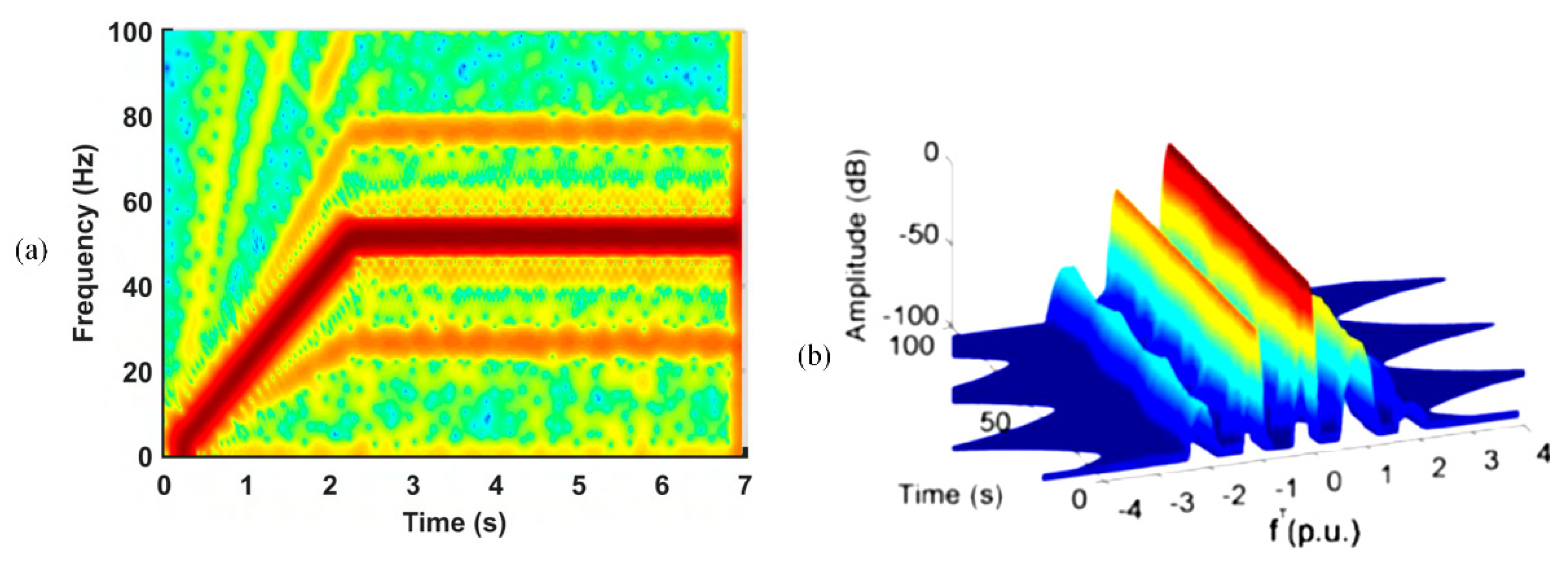
5.1. Signal-Processing Techniques

The signal-based methods use appropriate signal processing techniques to find fault characteristic frequencies from sampled sensor data. Comprehensive studies on steady-state MCSA and transient MCSA have been conducted to detect eccentricities.
As the FFT-based MCSA has the aforementioned drawbacks, a number of papers are focused on enhancing the fault feature and optimizing the feature extraction by applying Hilbert transform and Teager–Kaiser operator to the stator currents before performing FFT [91,92]. The adverse effect of spectral leakage is reduced and the signal-to-noise ratio is improved. A robust fault decision-making algorithm is proposed in [93] for MCSA to suppress false detection rate and achieve close to 100% accuracy on a tested IM with eccentricity and BRB faults.
More contribution has been focused on transient MCSA. The transient MCSAs are applied in machine startup to obtain time-frequency patterns. Short-time Fourier transform (STFT), Gabor, wavelets, Wigner–Ville distribution (WVD), and Hilbert–Huang transform (HHT) have been explored for the eccentricity faults [94,95,96,97,98,99,100]. It has been proved in [91] that the STFT has better extraction ability for fault components evolutions compared with discrete wavelet transform (DWT) in detecting ME. The continuous wavelet transform (CWT) is similar to the STFT, but the CWT has been proved to be less suitable for rotor fault components evolutions than the STFT [101]. Further, adaptive slope transform (AST) with optimal atom selection criterion has been proposed to improve the STFT and CWT so as to achieve a minimum ridge width [102,103]. The criterion asserts that the atom slope must be equal to the time derivative of the frequency along the harmonic trajectory. The evolution of each frequency component can be optimized as a thin line via the criterion. The WVD is a biquadratic distribution technique with inherent high-resolution, which offers perfect thin lines. However, its use is hindered by the cross terms which hamper the interpretation of distribution. The variants of WVD and prior notch filters have been adopted to suppress the cross terms [104,105]. A full comparison between all the above-mentioned methods has been done in the reference paper [101], and among which the STFT improved by AST is concluded as the best tool for ME detection.
Recent researchers have studied other techniques to present spectrum-like plots for the nonstationary cases as well. In [106], the filtered transient sideband harmonic is turned into a constant-frequency signal by polynomial-phase transform (PPT). Then, the FFT spectrum of such signal can be used to detect eccentricity. More literatures have been focused on a series of order tracking (OT) techniques [107,108,109,110]. The horizontal axis of order spectrum in angular domain represents the multiples of rotor speed and hence the velocity-dependent rotor faults can be depicted in a 2-D plot. An alternative approach of OT has been proposed in [111,112], where stator currents are expressed in rotor reference frame and the rescaling is performed after the time-frequency results of Gabor analysis. The reduced spectrum-like plot does not require large memory to store time-frequency distribution results, which makes it easier for industrial application. The results of traditional time-frequency pattern and OT spectrum are compared in Figure 5. The traditional time-frequency pattern tracks the fundamental frequency and eccentricity sideband frequencies from 0 Hz to 50 Hz, while the OT spectrum always presents like dealing with a stationary signal. Table 2 summarizes the signal processing techniques for eccentricity fault.

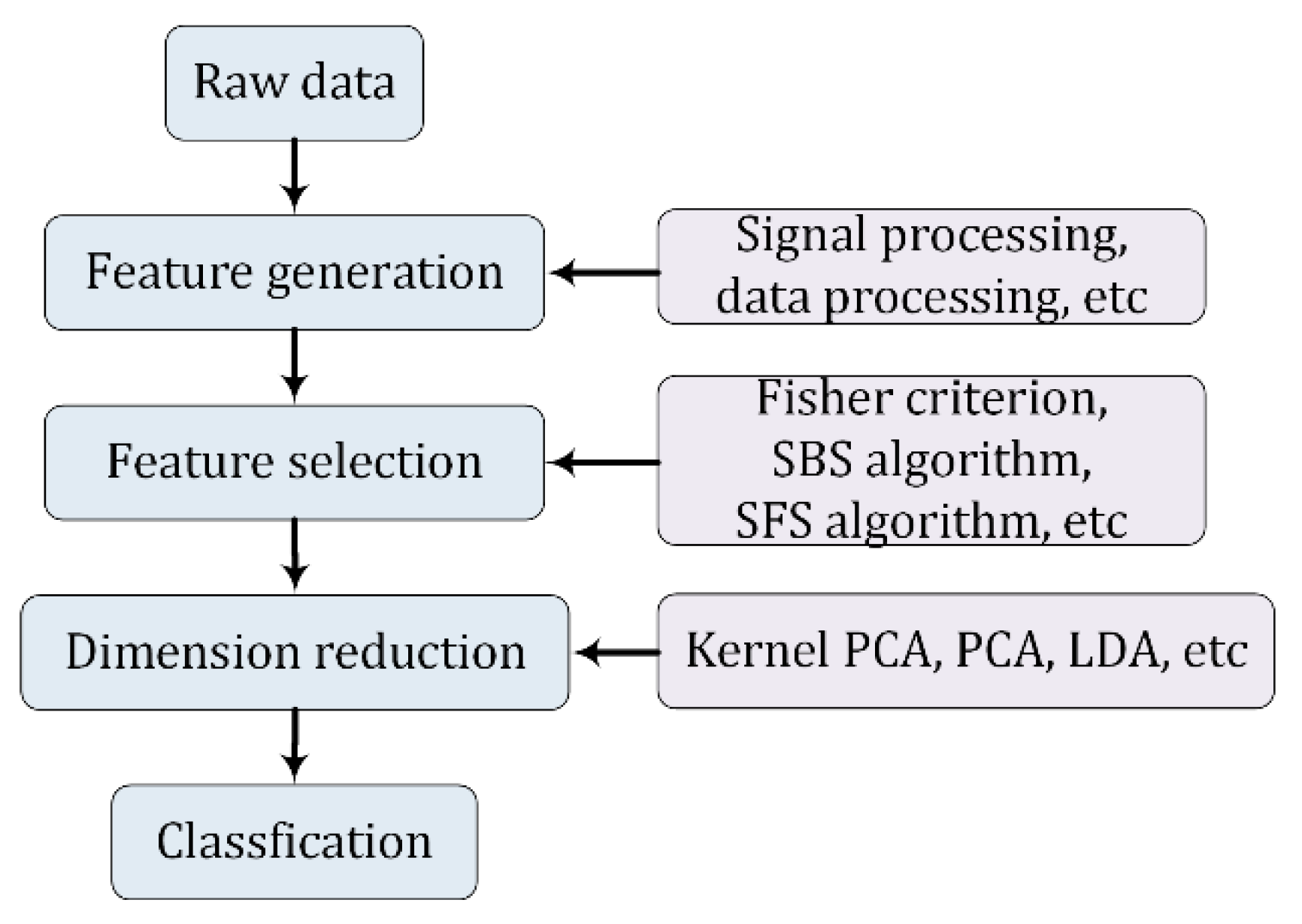
5.2. Data-Driven Algorithms

The data-driven method acts as an auxiliary artificial intelligence tool for fault classification and severity evaluation in literature. Various machine learning and statistical methods, such as neural network (NN), support vector machine (SVM), k-nearest neighbors (k-NN), linear discriminant analysis (LDA), and quadratic discriminant analysis (QDA), have been applied to eccentricity diagnosis. Data sources could be electrical, mechanical, acoustic, and their fusions [113]. Methods based on electrical data are within the scope and discussed herein.
Figure 6 presents a typical flow of data-driven algorithms for motor fault detection. In most cases for eccentricity detection, the data features are extracted from current or voltage signatures before fault classification. In [114], the LDA is used to classify the fault type and estimate the severity based on the amplitude of the main harmonics in MCSA or motor voltage signature analysis (MVSA). In [115], the fuzzy min-max (FMM) and classification and regression tree (CART) are used after MCSA to classify five different motor conditions including eccentricity. In [116], combined with MCSA, the k-NN has been used to classify SE and DE, and the fuzzy SVM has been employed to estimate the eccentricity degree.
The sign of an accurate data-based approach is to own a well-partitioned database. To succeed in this, the initial extracted features need to be carefully selected by researchers’ experience or feature selection algorithms. The goal of feature selection is to maximize the distance between classes. In addition to the feature selection, principal component analysis (PCA) is often required to reduce the dimension of the selected features because these features could still have mutual correlated information. The PCA is also a common means for visualization. In [117], the SE and rotor-side inter-turn short circuit (ITSC) of a turbo-generator are detected based on the data from flux probes and electrical sensors. Fisher criterion and sequential backward selection (SBS) algorithm are used and compared for feature selection. It is shown that the SBS algorithm with the Euclidean distance is better. In order to determine the optimal feature space dimension, the k-NN is used to measure the classification accuracy versus the dimension of new feature space. In this reference article, the PCA is used to verify the effectiveness in 3-D representation. In [118], a classical hierarchical classifier for eccentricity and bearing fault detection is proposed. After the feature generation by FFT and HHT, sequential forward search (SFS) algorithm is used for feature selection and PCA is used for dimension reduction. Then QDA is used as the first classifier for the super-category: normal and eccentricity. SVM is used as the second classifier for the sub-category: SE and DE.
It can be seen that the present data-driven methods based on electrical sensors often require efforts in the feature extraction and selection, which may need redesign for a new diagnosis task [119]. Recently, unsupervised feature learning algorithms, such as sparse filtering, have been applied to bearing defects detection based on vibration sensors. The raw sensor data can be transformed from original space into a feature space by such algorithms. Nonetheless, very few publications have reported the use of unsupervised feature learning algorithms in electrical sensor-based eccentricity detection. Therefore, the unsupervised feature learning techniques could be an interesting research subject for the eccentricity detection.
Last but not least, large numbers of samples are required for the data-driven methods in order to have a high probability of correct detection. However, the amount of computation can be greatly reduced if the fault features are previously proposed by the model-based approach, and the data-driven method only needs to provide the classification stage at this time. In the aforementioned [57], the features are the commanded voltages and the k-NN, LDA and QDA can be chosen for classification due to the distinct moving direction of Vd and Vq under healthy, eccentricity, PD and ITSC conditions, as shown in Figure 7.

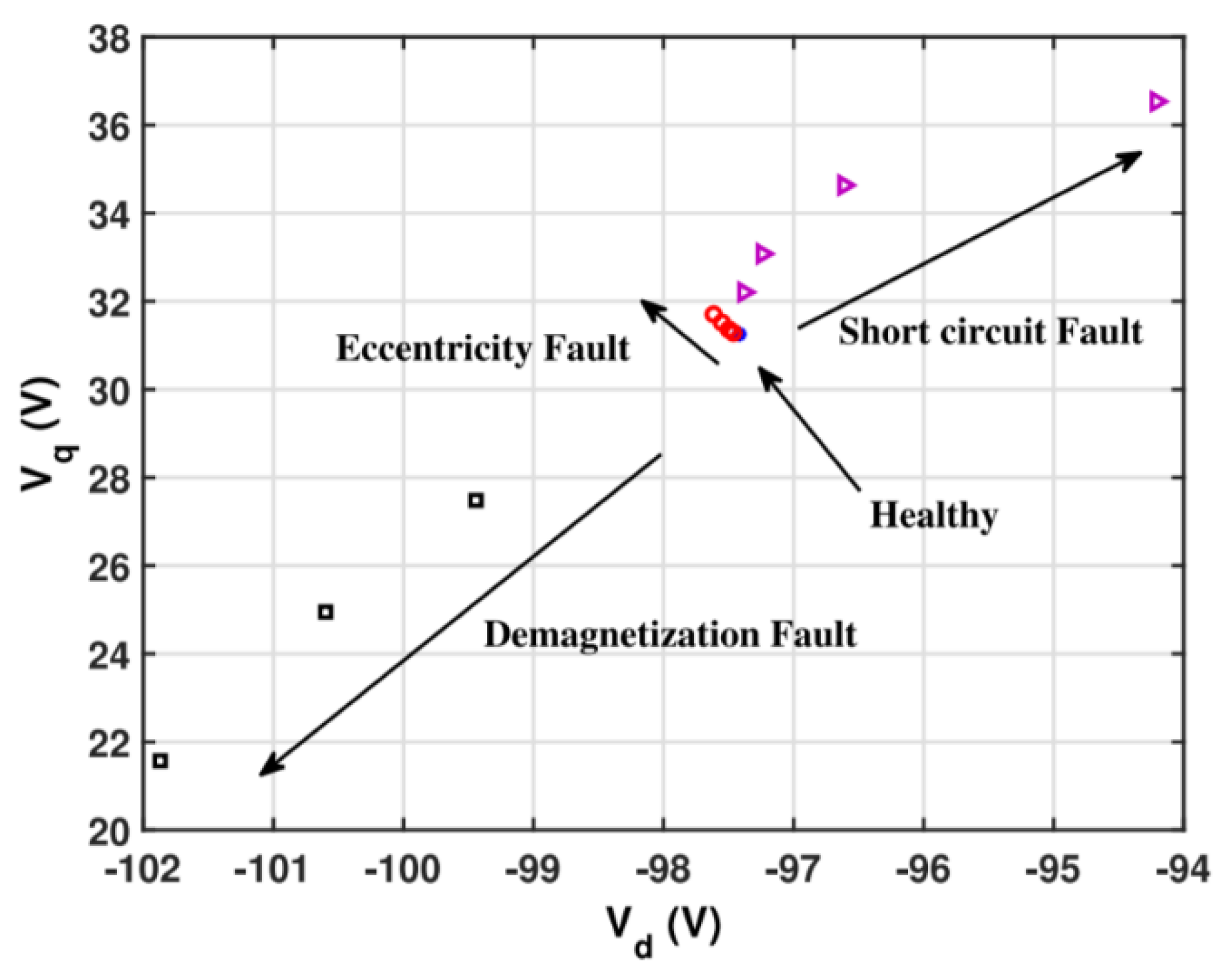
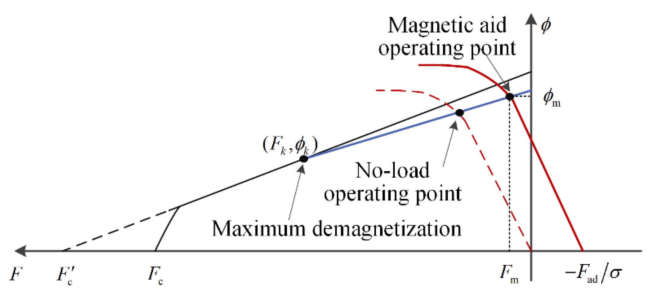
6. Separation with Other Faults

As the appearance of sideband patterns could be wrongly attributed to PD, ITSC, load torque oscillation, and shaft misalignment, the separation of eccentricity from the other faults has been considered in recent literature, and the discrimination ability should not be neglected in evaluating the feasibility of a diagnostic approach.

6.1. Separation with Load Torque Oscillation

The current or voltage harmonics due to rotor position dependent load torque oscillations usually have large magnitudes, which leads to an ambiguity in the diagnostics. The load torque oscillations can be produced by shaft misalignment, mass unbalance, transmission gear, etc. The load torque oscillation is usually simulated by an inertia disc with uneven mass distribution [120]. The distinctions between single frequency load torque oscillation and eccentricity have been studied by researchers. To distinguish between eccentricity and load torque oscillations of a closed-loop drive-connected IM, the fundamental negative sequence component of stator currents has been proposed as a mark of distinction, because the load torque oscillation does not belong to structural asymmetries, and it would not cause the fundamental negative sequence current [121]. However, whether the sequence fundamental negative sequence appear in the voltage or current signals depends on the controller bandwidth. The negative sequence component may also be produced by stator ITSC, yet this ambiguity can be excluded by analyzing the fundamental component of zero-sequence voltage. In [122], the spectral analyses of both instantaneous power factor and its phase angle have been found effective to separate them, but which require the measurements of all the stator voltages and currents.
The response of torque harmonic to the bandwidth of speed controller has been considered for the separation [123]. The fr torque harmonic shows opposite trends for the two cases and is suggested as the separation criterion. However, this criterion is much affected by the regulating range of the bandwidth and fails when both faults appear.
The separation has been also considered from the perspective of signal processing. The load torque oscillation produces phase modulation while the eccentricity produces amplitude modulation in stator currents. Based on this theory, pseudo-Wigner distribution has been used for analysis [124].
As the load torque oscillation does not produce anomalies in rotor MMF while the eccentricity does, the flux amplitude patterns monitored by embedded Hall sensors have been recently used to distinguish them in [125].

6.2. Separation with PD

The sideband patterns of MCSA were studied in the early stages in order to find differences between eccentricity and PD for PM motors. In [126,127], the (1 − 1/p) fs of MCSA is suggested for DE detection and the 7th negative sequence harmonic is suggested for SE. The remnant PM flux or the EMF–speed ratio is estimated to detect PD. However, the remnant flux of common PM materials has a negative temperature coefficient (αBr ≈ −0.03%/°C for SmCo), which has to be taken into account. Moreover, in [128], the (1 − 1/p) fs is found to be related to SE, which is inconsistent with the above conclusion. The (1 − 3/p) fs and (1 − 2/p) fs have been suggested for PD diagnosis. Therefore, the MCSA cannot provide reliable distinction.
As the air-gap variations affect the inductances significantly, the d-axis inductance Ld is considered in the aforementioned [65]. It is concluded that in the case of eccentricity, the magnetic field is deeply saturated at the narrower air gap, and the permeance is reduced at the wider air gap, leading to the final decrease of Ld. On the other side, if linear magnetic circuit is assumed, inductances are supposed to become larger based on the equations of MWFA. However, the practical no-load operating point is beneath the knee point of BH curve, and thus the Ld decrease caused by saturation is much likely to mask the Ld increase under the eccentricity case. Therefore, it is acknowledged that the effectiveness of indicator Ld is affected by the direction of eccentricity, the designed operating point, and the motor structure. This drawback has been indicated in [62], because in which the zigzag leakage inductance increases with eccentricity degree, which is consistent with the results of linear magnetic circuit MWFA. To overcome this drawback, an additional DC bias current has been further injected onto the d-axis to assist saturation, as shown in Figure 8, and this work is accomplished in [129]. The DC bias helps to distinguish eccentricity and PD offline successfully. Note that both the works in [65,129] have an implicit assumption that the recoil line and the demagnetization curve coincide.
Instead of exploiting the Ld saturation, the aforementioned work in [15] use the amplitude modulation of inductances to distinguish ME and PD online for an inverter-fed PMSM. The generated 2-D inverse transient complex inductance trajectories give intuitive distinction.
The aforementioned work in [57] also provides intuitive distinction between SE and PD. The flux linkages λd and λq have been found to be in distinct trends for different types of faults. Then the change direction of (Vd, Vq) in VdVq plane is affected and is used to distinguish the SE and PD faults.
In fact, intrusive sensor measurements can easily give clear graph comparison for the fault distinction. The aforementioned distributed search coils in [74] provide distinct intuitive voltage polar graphs for SE, DE, ME, and PD. Similarly, the aforementioned embedded Hall sensors in [78,121] can distinguish DE, ME, and PD by displaying the peaks of the flux waveforms.

6.3. Separation with ITSC

As the air-gap magnetic field distribution is deformed under both ITSC and eccentricity cases, the diagnosis and distinguishing of stator/rotor ITSC and eccentricity faults have been reported in the aforementioned [35,57,74,117]. Except for the invasive search coils, classification algorithms are commonly seen in literature. The separation with ITSC contributes a small proportion.

7. Discussion on Continued Research

The model-based, signal-based, and data-based eccentricity diagnostic approaches are suitable for applications with diverse properties and demands. The signal-based approaches are mostly proposed for startup process or feature extraction before data processing. The data-based approaches are basically studied for multiple faults classification in steady-state process. The model-based approaches have developed into all kinds of means and are also suitable for steady-state diagnosis. Moreover, the model-based approaches have clear theoretical basis for faults separation. These approaches could be used in combination in practice, such as in [57].
In Section 4, the model-based approaches have been categorized by the most prominent features and some subcategories inevitably overlap. For instance, the auxiliary-voltage-injection-based, the sensor-based approaches need simulation model analysis to provide performance prediction. In addition, it is challenging to distinguish eccentricity from other rotational faults, such as PD. Nevertheless, several methods based on auxiliary voltage injection, sensor detection and coordinate transform etc. are demonstrated to be valid in discrimination. Their attributes are presented in Table 3. To achieve a minimum cost, the injection based online approach is the best. To achieve sufficient robustness, the intrusive sensor based online approach is the best. The coordinate-transform-based approaches are less competitive compared with the other two. It can be inferred that the recent trend of diagnostic strategies for eccentricity is toward reliable low-cost noninvasive visualized online diagnostics without interfering with the normal operation, although it is not possible to achieve all these goals at present.
The aforementioned observer-based approach in Section 4.7 does not have the above drawbacks in theory. The ME, PD, and load torque oscillation could be separated by observing the stator inductances if a proper time-varying model observer was designed. The principle is shown in Figure 9, which presents the distortion of one stator phase inductance under ME and PD. The amplitude of stator inductance under ME is modulated by frequency fr, which is notably different from PD fault. In addition, the load torque oscillation hardly affects motor inductances. Then the observer-based approach could be effective.
Last but not least, the load torque oscillation produced by shaft misalignments involves nonlinear dynamics and it cannot be simulated by single frequency fluctuation. Therefore, the elimination of shaft misalignments effects in eccentricity detection is also worth to be investigated.

8. Conclusions

The modeling and diagnostic approaches for the eccentricity fault have been reviewed. In terms of modeling approaches, the MEC and MWFA are suitable for the early verification of diagnostic strategies, while the analytical methods are suitable for the electromagnetic analysis. The FEM is an effective verification tool for both modeling and diagnostic methods. The choice of modeling approaches depends on the specific selection of model-based approaches. In terms of diagnostic approaches, a reliable diagnosis requires accurate discrimination of ME, PD, and load torque oscillations, which have similar fault characteristics in the collected signals. The existing technologies have achieved real-time online visualized diagnosis and fault separation. The search coil-based diagnosis has the highest robustness while the injection-based diagnosis has the least practice cost. However, their shortcomings restrict the scope of application. The ideal solution is to develop a reliable low-cost noninvasive visualized online diagnostic without interfering with the normal operation. The observer-based diagnostic approach for eccentricity is suggested as the ongoing research interest.

Author Contributions

Investigation, writing—original draft preparation, Z.L.; writing—review, P.Z., S.H., J.H. All authors have read and agreed to the published version of the manuscript.

Funding

This research was funded by National Natural Science Foundation of China, grant number 52007090.

Conflicts of Interest

The authors declare no conflict of interest.

References

  1. Antonino-Daviu, J.A.; Quijano-Lopez, A.; Rubbiolo, M.; Climente-Alarcon, V. Advanced analysis of motor currents for the diagnosis of the rotor condition in electric motors operating in mining facilities. IEEE Trans. Ind. Appl. 2018, 54, 3934–3942. [Google Scholar] [CrossRef]
  2. Choi, S.; Haque, M.S.; Tarek, M.T.B.; Mulpuri, V.; Duan, Y.; Das, S.; Garg, V.; Ionel, D.M.; Masrur, M.A.; Mirafzal, B.; et al. Fault diagnosis techniques for permanent magnet ac machine and drives—A review of current state of the art. IEEE Trans. Transp. Electrif. 2018, 4, 444–463. [Google Scholar] [CrossRef]
  3. Henao, H.; Capolino, G.A.; Fernandez-Cabanas, M.; Filippetti, F.; Bruzzese, C.; Strangas, E.; Pusca, R.; Estima, J.; Riera-Guasp, M.; Hedayati-Kia, S. Trends in fault diagnosis for electrical machines: A review of diagnostic techniques. IEEE Ind. Electron. Mag. 2014, 8, 31–42. [Google Scholar] [CrossRef]
  4. Artigao, E.; Honrubia-Escribano, A.; Gómez-Lázaro, E. In-service wind turbine DFIG diagnosis using current signature analysis. IEEE Trans. Ind. Electron. 2020, 67, 2262–2271. [Google Scholar] [CrossRef]
  5. Faiz, J.; Nejadi-Koti, H. Eccentricity fault diagnosis indices for permanent magnet machines: State-of-the-art. IET Electr. Power Appl. 2019, 13, 1241–1254. [Google Scholar] [CrossRef]
  6. Faiz, J.; Ojaghi, M. Different indexes for eccentricity faults diagnosis in three-phase squirrel-cage induction motors: A review. Mechatronics 2009, 19, 2–13. [Google Scholar] [CrossRef]
  7. Faiz, J.; Moosavi, S. Eccentricity fault detection—From induction machines to DFIG—A review. Renew. Sustain. Energy Rev. 2016, 55, 169–179. [Google Scholar] [CrossRef]
  8. Salah, A.A.; Dorrell, D.G.; Guo, Y. A Review of the Monitoring and Damping Unbalanced Magnetic Pull in Induction Machines Due to Rotor Eccentricity. IEEE Trans. Ind. Appl. 2019, 55, 2569–2580. [Google Scholar] [CrossRef]
  9. Aggarwal, A.; Strangas, E.G. Review of Detection Methods of Static Eccentricity for Interior Permanent Magnet Synchronous Machine. Energies 2019, 12, 4105. [Google Scholar] [CrossRef] [Green Version]
  10. Riera-Guasp, M.; Antonino-Daviu, J.A.; Capolino, G.A. Advances in electrical machine, power electronic, and drive condition monitoring and fault detection: State of the art. IEEE Trans. Ind. Electron. 2014, 62, 1746–1759. [Google Scholar] [CrossRef]
  11. Faiz, J.; Ghods, M.; Tajdyni, A. Dynamic air gap asymmetry fault detection in single-sided linear induction motors. IET Electr. Power Appl. 2019, 14, 605–613. [Google Scholar] [CrossRef]
  12. Di, C.; Bao, X.; Wang, H.; Lv, Q.; He, Y. Modeling and analysis of unbalanced magnetic pull in cage induction motors with curved dynamic eccentricity. IEEE Trans. Magn. 2015, 51, 1–7. [Google Scholar]
  13. Nandi, S.; Toliyat, H.A.; Li, X. Condition monitoring and fault diagnosis of electrical motors—A review. IEEE Trans. Energy Convers. 2005, 20, 719–729. [Google Scholar] [CrossRef]
  14. Nandi, S.; Ahmed, S.; Toliyat, H.A. Detection of rotor slot and other eccentricity related harmonics in a three phase induction motor with different rotor cages. IEEE Trans. Energy Convers. 2001, 16, 253–260. [Google Scholar] [CrossRef]
  15. Liu, Z.; Huang, J.; He, S. Diagnosis of air-gap eccentricity and partial demagnetisation of an interior permanent magnet synchronous motor based on inverse transient complex inductance vector theory. IET Electr. Power Appl. 2018, 12, 1166–1175. [Google Scholar] [CrossRef]
  16. Liu, Z.; Huang, J.; Li, B. Diagnosing and distinguishing rotor eccentricity from partial demagnetisation of interior PMSM based on fluctuation of high-frequency d-axis inductance and rotor flux. IET Electr. Power Appl. 2017, 11, 1265–1275. [Google Scholar] [CrossRef]
  17. Iamamura, B.A.T.; Le Menach, Y.; Tounzi, A.; Sadowski, N.; Guillot, E. Study of static and dynamic eccentricities of a synchronous generator using 3-D FEM. IEEE Trans. Magn. 2010, 46, 3516–3519. [Google Scholar] [CrossRef]
  18. Mohr, M.; Bíró, O.; Stermecki, A.; Diwoky, F. An extended finite element based model approach for permanent magnet synchronous machines including rotor eccentricity. In Proceedings of the 39th Annual Conference of IEEE Industrial Electronics Society, Vienna, Austria, 10–13 November 2013; pp. 2596–2601. [Google Scholar]
  19. Fu, J.; Zhu, C. Subdomain model for predicting magnetic field in slotted surface mounted permanent-magnet machines with rotor eccentricity. IEEE Trans. Magn. 2012, 48, 1906–1917. [Google Scholar] [CrossRef]
  20. Taghipour Boroujeni, S.; Jalali, P.; Bianchi, N. Analytical modeling of no-load eccentric slotted surface-mounted PM machines: Cogging torque and radial force. IEEE Trans. Magn. 2017, 53, 1–8. [Google Scholar] [CrossRef]
  21. Li, Y.; Lu, Q.; Zhu, Z.Q. Unbalanced magnetic force prediction in permanent magnet machines with rotor eccentricity by improved superposition method. IET Electr. Power Appl. 2017, 11, 1095–1104. [Google Scholar] [CrossRef]
  22. Li, Y.; Lu, Q.; Zhu, Z.Q.; Wu, D.; Li, G. Superposition method for cogging torque prediction in permanent magnet machines with rotor eccentricity. IEEE Trans. Magn. 2016, 52, 1–10. [Google Scholar] [CrossRef]
  23. Torregrossa, D.; Khoobroo, A.; Fahimi, B. Prediction of acoustic noise and torque pulsation in PM synchronous machines with static eccentricity and partial demagnetization using field reconstruction method. IEEE Trans. Ind. Electron. 2012, 59, 934–944. [Google Scholar] [CrossRef]
  24. Ajily, E.; Ardebili, M.; Abbaszadeh, K. Magnet defect and rotor eccentricity modeling in axial-flux permanent-magnet machines via 3-D field reconstruction method. IEEE Trans. Energy Convers. 2016, 31, 486–495. [Google Scholar] [CrossRef]
  25. Jalali, P.; Taghipour Boroujeni, S.; Bianchi, N. Analytical modeling of slotless eccentric surface-mounted PM machines using a conformal transformation. IEEE Trans. Energy Convers. 2017, 32, 658–666. [Google Scholar] [CrossRef]
  26. Toliyat, H.A. Electric Machines: Modeling, Condition Monitoring, and Fault Diagnosis; CRC Press: Boca Raton, FL, USA, 2012. [Google Scholar]
  27. Faiz, J.; Ghasemi-Bijan, M. Estimation of induction machine inductances using three-dimensional magnetic equivalent circuit. IET Electr. Power Appl. 2017, 9, 117–127. [Google Scholar] [CrossRef]
  28. Toliyat, H.A.; Al-Nuaim, N.A. Simulation and detection of dynamic air-gap eccentricity in salient-pole synchronous machines. IEEE Trans. Ind. Appl. 1999, 35, 86–93. [Google Scholar] [CrossRef]
  29. Faiz, J.; Tabatabaei, I. Extension of winding function theory for nonuniform air gap in electric machinery. IEEE Trans. Magn. 2002, 38, 3654–3657. [Google Scholar] [CrossRef]
  30. Faiz, J.; Ojaghi, M. Unified winding function approach for dynamic simulation of different kinds of eccentricity faults in cage induction machines. IET Electr. Power Appl. 2009, 3, 461–470. [Google Scholar] [CrossRef]
  31. Ojaghi, M.; Nasiri, S. Modeling eccentric squirrel-cage induction motors with slotting effect and saturable teeth reluctances. IEEE Trans. Energy Convers. 2014, 29, 619–627. [Google Scholar] [CrossRef]
  32. Pal, R.S.C.; Mohanty, A.R.A. Simplified Dynamical Model of Mixed Eccentricity Fault in a Three-Phase Induction Motor. IEEE Trans. Ind. Electron. 2021, 68, 4341–4350. [Google Scholar] [CrossRef]
  33. Huang, J.; Li, B.; Jiang, H.; Kang, M. Analysis and control of multiphase permanent-magnet bearingless motor with a single set of half-coiled winding. IEEE Trans. Ind. Electron. 2014, 61, 3137–3145. [Google Scholar] [CrossRef]
  34. Park, J.K.; Hur, J. Detection of inter-turn and dynamic eccentricity faults using stator current frequency pattern in IPM-type BLDC motors. IEEE Trans. Ind. Electron. 2016, 63, 1771–1780. [Google Scholar] [CrossRef]
  35. Féki, N.; Clerc, G.; Velex, P. Gear and motor fault modeling and detection based on motor current analysis. Electr. Power Syst. Res. 2013, 95, 28–37. [Google Scholar] [CrossRef]
  36. Kaikaa, M.Y.; Hadjami, M.; Khezzar, A. Effects of the simultaneous presence of static eccentricity and broken rotor bars on the stator current of induction machine. IEEE Trans. Ind. Electron. 2014, 61, 2452–2463. [Google Scholar] [CrossRef]
  37. Ebrahimi, B.M.; Faiz, J. Configuration impacts on eccentricity fault detection in permanent magnet synchronous motors. IEEE Trans. Magn. 2012, 48, 903–906. [Google Scholar] [CrossRef]
  38. Ebrahimi, B.M.; Faiz, J.; Araabi, B.N. Pattern identification for eccentricity fault diagnosis in permanent magnet synchronous motors using stator current monitoring. IET Electr. Power Appl. 2010, 4, 418–430. [Google Scholar] [CrossRef]
  39. Ebrahimi, B.M.; Faiz, J. Diagnosis and performance analysis of three-phase permanent magnet synchronous motors with static, dynamic and mixed eccentricity. IET Electr. Power Appl. 2010, 4, 53–66. [Google Scholar] [CrossRef]
  40. Bruzzese, C.; Joksimovic, G. Harmonic signatures of static eccentricities in the stator voltages and in the rotor current of no-load salient-pole synchronous generators. IEEE Trans. Ind. Electron. 2011, 58, 1606–1624. [Google Scholar] [CrossRef]
  41. Faiz, J.; Ebrahimi, B.M.; Akin, B.; Toliyat, H.A. Comprehensive eccentricity fault diagnosis in induction motors using finite element method. IEEE Trans. Magn. 2009, 45, 1764–1767. [Google Scholar] [CrossRef]
  42. Li, X.; Wu, Q.; Nandi, S. Performance analysis of a three-phase induction machine with inclined static eccentricity. IEEE Trans. Ind. Appl. 2010, 43, 531–541. [Google Scholar] [CrossRef]
  43. Ojaghi, M.; Aghmasheh, R.; Sabouri, M. Model-based exact technique to identify type and degree of eccentricity faults in induction motors. IET Electr. Power Appl. 2016, 10, 706–713. [Google Scholar] [CrossRef]
  44. Faiz, J.; Ojaghi, M. Stator inductance fluctuation of induction motor as an eccentricity fault index. IEEE Trans. Magn. 2011, 47, 1775–1785. [Google Scholar] [CrossRef]
  45. Faiz, J.; Pakdelian, S. Diagnosis of static eccentricity in switched reluctance motors based on mutually induced voltages. IEEE Trans. Magn. 2008, 44, 2029–2034. [Google Scholar] [CrossRef]
  46. Lasjerdi, H.; Nasiri-Gheidari, Z.; Tootoonchian, F. Online Static/Dynamic Eccentricity Fault Diagnosis in Inverter-Driven Electrical Machines Using Resolver Signals. IEEE Trans. Energy Convers. 2020, 35, 1973–1980. [Google Scholar] [CrossRef]
  47. Cameron, J.R.; Thomson, W.T.; Dow, A.B. Vibration and current monitoring for detecting air-gap eccentricity in large induction motors. IEE Proc. B Electr. Power Appl. 1986, 133, 155–163. [Google Scholar] [CrossRef]
  48. Nandi, S.; Bharadwaj, R.M.; Toliyat, H.A. Performance analysis of a three-phase induction motor under mixed eccentricity condition. IEEE Trans. Energy Convers. 2002, 17, 392–399. [Google Scholar] [CrossRef]
  49. Nandi, S.; Ilamparithi, T.C.; Lee, S.B.; Hyun, D. Detection of eccentricity faults in induction machines based on nameplate parameters. IEEE Trans. Ind. Electron. 2011, 58, 1673–1683. [Google Scholar] [CrossRef]
  50. Ilamparithi, T.C.; Nandi, S. Identification of spectral components in the line current of eccentric salient pole machines using a binomial series-based inverse air-gap function. IET Electr. Power Appl. 2013, 7, 303–312. [Google Scholar] [CrossRef]
  51. Ilamparithi, T.C.; Nandi, S. Detection of eccentricity faults in three-phase reluctance synchronous motor. IEEE Trans. Ind. Appl. 2012, 48, 1307–1317. [Google Scholar] [CrossRef]
  52. Liu, Z.; Yin, X.; Zhang, Z.; Chen, D.; Chen, W. Online rotor mixed fault diagnosis based on spectrum analysis of instantaneous power in squirrel cage induction motors. IEEE Trans. Energy Convers. 2004, 19, 485–490. [Google Scholar] [CrossRef]
  53. Faiz, J.; Ojaghi, M. Instantaneous-power harmonics as indexes for mixed eccentricity fault in mains-fed and open/closed-loop drive-connected squirrel-cage induction motors. IEEE Trans. Ind. Electron. 2009, 56, 4718–4726. [Google Scholar] [CrossRef]
  54. Drif, M.; Cardoso, A.J.M. Air-gap-eccentricity fault diagnosis, in three-phase induction motors, by the complex apparent power signature analysis. IEEE Trans. Ind. Electron. 2008, 55, 1404–1410. [Google Scholar] [CrossRef]
  55. Faiz, J.; Moosavi, S.M.M. Detection of mixed eccentricity fault in doubly-fed induction generator based on reactive power spectrum. IET Electr. Power Appl. 2017, 11, 1076–1084. [Google Scholar] [CrossRef]
  56. Hu, N.Q.; Xia, L.R.; Gu, F.S.; Qin, G.J. A novel transform demodulation algorithm for motor incipient fault detection. IEEE Trans. Instrum. Meas. 2011, 60, 480–487. [Google Scholar] [CrossRef]
  57. Haddad, R.Z.; Lopez, C.A.; Foster, S.N.; Strangas, E.G. A voltage-based approach for fault detection and separation in permanent magnet synchronous machines. IEEE Trans. Ind. Appl. 2017, 53, 5305–5314. [Google Scholar] [CrossRef]
  58. Gyftakis, K.N.; Kappatou, J.C. A novel and effective method of static eccentricity diagnosis in three-phase PSH induction motors. IEEE Trans. Energy Convers. 2013, 28, 405–412. [Google Scholar] [CrossRef]
  59. Wu, L.; Lu, B.; Huang, X.; Habetler, G.; Harley, G. Improved online condition monitoring using static eccentricity-induced negative sequence current information in induction machines. In Proceedings of the 31st Annual Conference of IEEE Industrial Electronics Society, Raleigh, NC, USA, 6–10 November 2005; pp. 1737–1742. [Google Scholar]
  60. Bruzzese, C. Diagnosis of eccentric rotor in synchronous machines by analysis of split-phase currents—Part I: Theoretical analysis. IEEE Trans. Ind. Electron. 2014, 61, 4193–4205. [Google Scholar] [CrossRef]
  61. Bruzzese, C. Diagnosis of eccentric rotor in synchronous machines by analysis of split-phase currents—Part II: Experimental analysis. IEEE Trans. Ind. Electron. 2014, 61, 4206–4216. [Google Scholar] [CrossRef]
  62. Hyun, D.; Hong, J.; Lee, S.B.; Kim, K.; Wiedenbrug, E.J.; Teska, M.; Nandi, S.; Chelvan, I.T. Automated monitoring of air-gap eccentricity for inverter-fed induction motors under standstill conditions. IEEE Trans. Ind. Appl. 2011, 47, 1257–1266. [Google Scholar] [CrossRef]
  63. Hyun, D.; Lee, S.; Hong, J.; Lee, S.B.; Nandi, S. Detection of air-gap eccentricity for induction motors using the single-phase rotation test. IEEE Trans. Energy Convers. 2012, 27, 689–696. [Google Scholar] [CrossRef]
  64. Hong, J.; Hyun, D.; Lee, S.B.; Kral, C. Offline monitoring of air-gap eccentricity for inverter-fed induction motors based on the differential inductance. IEEE Trans. Ind. Appl. 2013, 49, 2533–2542. [Google Scholar] [CrossRef]
  65. Hong, J.; Lee, S.B.; Kral, C.; Haumer, A. Detection of air-gap eccentricity for permanent magnet synchronous motors based on the d-axis inductance. IEEE Trans. Power Electron. 2012, 27, 2605–2612. [Google Scholar] [CrossRef]
  66. Aggarwal, A.; Allafi, I.M.; Strangas, E.G.; Agapiou, J.S. Off-Line Detection of Static Eccentricity of PMSM Robust to Machine Operating Temperature and Rotor Position Misalignment Using Incremental Inductance Approach. IEEE Trans. Transp. Electrif. 2021, 7, 161–169. [Google Scholar] [CrossRef]
  67. Wolbank, T.M.; Macheiner, P.E. Monitoring of static and dynamic air gap eccentricity of inverter fed induction machine drives. IECON. In Proceedings of the 32nd Annual Conference of IEEE Industrial Electronics Society, Paris, France, 7–10 November 2006; pp. 1504–1509. [Google Scholar]
  68. Wolbank, T.M.; Macheiner, P.E. Modulation of transient reactances of induction machines caused by different types of eccentricity. In Proceedings of the 6th IEEE International Symposium on Diagnostics for Electrical Machines, Power Electronics and Drives, Cracow, Poland, 6–8 September 2007; pp. 89–94. [Google Scholar]
  69. Samonig, M.A.; Wolbank, T.M. Exploiting rotor slotting harmonics to determine and separate static and dynamic air-gap eccentricity in induction machines. In Proceedings of the 11th IEEE International Symposium on Diagnostics for Electrical Machines, Power Electronics and Drives, Tinos, Greece, 29 August–1 September 2017; pp. 52–57. [Google Scholar]
  70. Torkaman, H.; Afjei, E.; Yadegari, P. Static, dynamic, and mixed eccentricity faults diagnosis in switched reluctance motors using transient finite element method and experiments. IEEE Trans. Magn. 2012, 48, 2254–2264. [Google Scholar] [CrossRef]
  71. Torkaman, H.; Afjei, E. Sensorless Method for eccentricity fault monitoring and diagnosis in switched reluctance machines based on stator voltage signature. IEEE Trans. Magn. 2013, 49, 912–920. [Google Scholar] [CrossRef]
  72. Torkaman, H.; Afjei, E. Comprehensive detection of eccentricity fault in switched reluctance machines using high-frequency pulse injection. IEEE Trans. Power Electron. 2013, 28, 1382–1390. [Google Scholar] [CrossRef]
  73. Huang, X.; Habetler, T.G.; Harley, R.G.; Wiedenbrug, E.J. Using a surge tester to detect rotor eccentricity faults in induction motors. IEEE Trans. Ind. Appl. 2007, 43, 1183–1190. [Google Scholar] [CrossRef]
  74. Da, Y.; Shi, X.; Krishnamurthy, M. A new approach to fault diagnostics for permanent magnet synchronous machines using electromagnetic signature analysis. IEEE Trans. Power Electron. 2013, 28, 4104–4112. [Google Scholar] [CrossRef]
  75. Zeng, C.; Huang, S.; Lei, J.; Wan, Z.; Yang, Y. Online Rotor Fault Diagnosis of Permanent Magnet Synchronous Motors Based on Stator Tooth Flux. IEEE Trans. Ind. Appl. 2021, 57, 2366–2377. [Google Scholar] [CrossRef]
  76. Kang, K.; Song, J.; Kang, C.; Sung, S.; Jang, G. Real-time detection of the dynamic eccentricity in permanent-magnet synchronous motors by monitoring speed and back EMF induced in an additional winding. IEEE Trans. Ind. Electron. 2017, 64, 7191–7200. [Google Scholar] [CrossRef]
  77. Dorrell, D.G.; Salah, A. Detection of rotor eccentricity in wound rotor induction machines using pole-specific search coils. IEEE Trans. Magn. 2015, 51, 1–4. [Google Scholar] [CrossRef]
  78. Park, Y.; Fernandez, D.; Lee, S.B.; Hyun, D.; Jeong, M.; Kommuri, S.K.; Cho, C.; Reigosa, D.D.; Briz, F. Online Detection of Rotor Eccentricity and Demagnetization Faults in PMSMs Based on Hall-Effect Field Sensor Measurements. IEEE Trans. Ind. Appl. 2019, 55, 2499–2509. [Google Scholar] [CrossRef]
  79. Herman, J.; Begus, S.; Mihalic, P.; Bojkovski, J. Novel Method for Direct Measurement of Air Gap Anomalies in Direct-Drive Electrical Motors. IEEE Trans. Ind. Electron. 2020, 67, 2422–2429. [Google Scholar] [CrossRef]
  80. Capolino, G.; Romary, R.; Hénao, H.; Pusca, R. State of the Art on Stray Flux Analysis in Faulted Electrical Machines. In Proceedings of the IEEE Workshop on Electrical Machines Design, Control and Diagnosis, Athens, Greece, 22–23 April 2019; pp. 181–187. [Google Scholar]
  81. Lee, S.-B.; Shin, J.; Park, Y.; Kim, H.; Kim, J. Reliable Flux based Detection of Induction Motor Rotor Faults from the 5th Rotor Rotational Frequency Sideband. IEEE Trans. Ind. Electron. 2020, 68, 7874–7883. [Google Scholar] [CrossRef]
  82. Gyftakis, K.N.; Panagiotou, P.A.; Lee, S.B. Generation of Mechanical Frequency Related Harmonics in the Stray Flux Spectra of Induction Motors Suffering from Rotor Electrical Faults. IEEE Trans. Ind. Appl. 2020, 56, 4796–4803. [Google Scholar] [CrossRef]
  83. Ramirez-Nunez, J.A.; Antonino-Daviu, J.A.; Climente-Alarcón, V.; Quijano-López, A.; Razik, H.; Osornio-Rios, R.A.; Romero-Troncoso, R.D. Evaluation of the Detectability of Electromechanical Faults in Induction Motors Via Transient Analysis of the Stray Flux. IEEE Trans. Ind. Appl. 2018, 54, 4324–4332. [Google Scholar] [CrossRef]
  84. Vitek, O.; Janda, M.; Hajek, V.; Bauer, P. Detection of eccentricity and bearings fault using stray flux monitoring. In Proceedings of the 8th IEEE Symposium on Diagnostics for Electrical Machines, Power Electronics and Drives, Bologna, Italy, 5–8 September 2011; pp. 456–461. [Google Scholar]
  85. Ceban, A.; Pusca, R.; Romary, R. Study of rotor faults in induction motors using external magnetic field analysis. IEEE Trans. Ind. Electron. 2012, 59, 2082–2093. [Google Scholar] [CrossRef]
  86. Poncelas, O.; Rosero, J.A.; Cusido, J.; Ortega, J.A.; Romeral, L. Motor fault detection using a rogowski sensor without an integrator. IEEE Trans. Ind. Electron. 2009, 56, 4062–4070. [Google Scholar] [CrossRef] [Green Version]
  87. He, Y.; Zhang, Z.J.; Tao, W.Q.; Wang, X.L.; Gerada, D.; Gerada, C.; Gao, P. A New External Search Coil Based Method to Detect Detailed Static Air-Gap Eccentricity Position in Non-Salient Pole Synchronous Generators. IEEE Trans. Ind. Electron. 2020, 68, 7535–7544. [Google Scholar] [CrossRef]
  88. Kim, H. On-line mechanical unbalance estimation for permanent magnet synchronous machine drives. IET Electr. Power Appl. 2009, 3, 178–186. [Google Scholar] [CrossRef]
  89. Pilloni, A.; Pisano, A.; Usai, E.; Puche-Panadero, R. Detection of rotor broken bar and eccentricity faults in induction motors via second order sliding mode observer. In Proceedings of the 51st IEEE Conference on Decision and Control, Maui, HI, USA, 10–13 December 2012; pp. 7614–7619. [Google Scholar]
  90. Pons-Llinares, J.; Antonino-Daviu, J.A.; Riera-Guasp, M.; Pineda-Sanchez, M.; Climente-Alarcon, V. Induction motor diagnosis based on a transient current analytic wavelet transform via frequency B-splines. IEEE Trans. Ind. Electron. 2011, 58, 1530–1544. [Google Scholar] [CrossRef]
  91. Puche-Panadero, R.; Pineda-Sanchez, M.; Riera-Guasp, M.; Roger-Folch, J.; Hurtado-Perez, E.; Perez-Cruz, J. Improved resolution of the MCSA method via Hilbert transform, enabling the diagnosis of rotor asymmetries at very low slip. IEEE Trans. Energy Convers. 2009, 24, 52–59. [Google Scholar] [CrossRef]
  92. Pineda-Sanchez, M.; Puche-Panadero, R.; Riera-Guasp, M.; Perez-Cruz, J.; Roger-Folch, J.; Pons-Llinares, J.; Climente-Alarcon, V.; Antonino-Daviu, J.A. Application of the Teager–Kaiser energy operator to the fault diagnosis of induction motors. IEEE Trans. Energy Convers. 2013, 28, 1036–1044. [Google Scholar] [CrossRef]
  93. Choi, S.; Pazouki, E.; Baek, J.; Bahrami, H.R. Iterative condition monitoring and fault diagnosis scheme of electric motor for harsh industrial application. IEEE Trans. Ind. Electron. 2015, 62, 1760–1769. [Google Scholar] [CrossRef]
  94. Rajagopalan, S.; Aller, J.M.; Restrepo, J.A.; Habetler, T.G.; Harley, R.G. Detection of rotor faults in brushless DC motors operating under nonstationary conditions. IEEE Trans. Ind. Appl. 2006, 42, 1464–1477. [Google Scholar] [CrossRef] [Green Version]
  95. Riera-Guasp, M.; Pineda-Sanchez, M.; Perez-Cruz, J.; Puche-Panadero, R.; Roger-Folch, J.; Antonino-Daviu, J.A. Diagnosis of induction motor faults via Gabor analysis of the current in transient regime. IEEE Trans. Instrum. Meas. 2012, 61, 1583–1596. [Google Scholar] [CrossRef]
  96. Riera-Guasp, M.; Antonino-Daviu, J.A.; Pineda-Sanchez, M.; Puche-Panadero, R.; Pérez-Cruz, J. A general approach for the transient detection of slip-dependent fault components based on the discrete wavelet transform. IEEE Trans. Ind. Electron. 2008, 55, 4167–4180. [Google Scholar] [CrossRef]
  97. Antonino-Daviu, J.; Rodriguez, P.J.; Riera-Guasp, M.; Pineda-Sanchez, M.; Arkkio, A. Detection of combined faults in induction machines with stator parallel branches through the DWT of the startup current. Mech. Syst. Signal Process. 2009, 23, 2336–2351. [Google Scholar] [CrossRef]
  98. Rajagopalan, S.; Restrepo, J.A.; Aller, J.M.; Habetler, T.G.; Harley, R.G. Nonstationary motor fault detection using recent quadratic time–frequency representations. IEEE Trans. Ind. Appl. 2008, 44, 735–744. [Google Scholar] [CrossRef]
  99. Pons-Llinares, J.; Antonino-Daviu, J.A.; Riera-Guasp, M.; Bin Lee, S.; Kang, T.-J.; Yang, C. Advanced induction motor rotor fault diagnosis via continuous and discrete time–frequency tools. IEEE Trans. Ind. Electron. 2015, 62, 1791–1802. [Google Scholar] [CrossRef]
  100. Elbouchikhi, E.; Choqueuse, V.; Amirat, Y.; Benbouzid, M.E.; Turri, S. An Efficient Hilbert–Huang Transform-Based Bearing Faults Detection in Induction Machines. IEEE Trans. Energy Convers. 2017, 32, 401–413. [Google Scholar] [CrossRef]
  101. Fernandez-Cavero, V.; Morinigo-Sotelo, D.; Duque-Perez, O.; Pons-Llinares, J. A Comparison of Techniques for Fault Detection in Inverter-fed Induction Motors in Transient Regime. IEEE Access 2017, 5, 8048–8063. [Google Scholar] [CrossRef]
  102. Pons-Llinares, J.; Antonino-Daviu, J.; Roger-Folch, J.; Morinigo-Sotelo, D.; Duque-Perez, O. Mixed eccentricity diagnosis in Inverter-Fed Induction Motors via the Adaptive Slope Transform of transient stator currents. Mech. Syst. Signal Process. 2014, 48, 423–435. [Google Scholar] [CrossRef]
  103. Pons-Llinares, J.; Riera-Guasp, M.; Antonino-Daviu, J.A.; Habetler, T.G. Pursuing optimal electric machines transient diagnosis: The adaptive slope transform. Mech. Syst. Signal Process. 2016, 80, 553–569. [Google Scholar] [CrossRef]
  104. Climente-Alarcon, V.; Antonino-Daviu, J.A.; Riera-Guasp, M.; Puche-Panadero, R.; Escobar, L. Application of the Wigner–Ville distribution for the detection of rotor asymmetries and eccentricity through high-order harmonics. Electr. Power Syst. Res. 2012, 91, 28–36. [Google Scholar] [CrossRef]
  105. Climente-Alarcon, V.; Antonino-Daviu, J.A.; Riera-Guasp, M.; Vlcek, M. Induction motor diagnosis by advanced notch FIR filters and the Wigner–Ville distribution. IEEE Trans. Ind. Electron. 2014, 61, 4217–4227. [Google Scholar] [CrossRef] [Green Version]
  106. Pineda-Sanchez, M.; Riera-Guasp, M.; Roger-Folch, J.; Antonino-Daviu, J.A.; Perez-Cruz, J.; Puche-Panadero, R. Diagnosis of induction motor faults in time-varying conditions using the polynomial-phase transform of the current. IEEE Trans. Ind. Electron. 2011, 58, 1428–1439. [Google Scholar] [CrossRef] [Green Version]
  107. Akar, M. Detection of a static eccentricity fault in a closed loop driven induction motor by using the angular domain order tracking analysis method. Mech. Syst. Signal Process. 2013, 34, 173–182. [Google Scholar] [CrossRef]
  108. Borghesani, P.; Pennacchi, P.; Chatterton, S.; Ricci, R. The velocity synchronous discrete Fourier transform for order tracking in the field of rotating machinery. Mech. Syst. Signal Process. 2014, 44, 118–133. [Google Scholar] [CrossRef]
  109. Gong, X.; Qiao, W. Current-based eccentricity detection for direct-drive wind turbines via synchronous sampling. In Proceedings of the 2013 IEEE Energy Conversion Congress and Exposition, Denver, CO, USA, 15–19 September 2013; pp. 2972–2976. [Google Scholar]
  110. Gong, X.; Qiao, W. Current-based mechanical fault detection for direct-drive wind turbines via synchronous sampling and impulse detection. IEEE Trans. Ind. Electron. 2015, 62, 1693–1702. [Google Scholar] [CrossRef]
  111. Sapena-Bano, A.; Pineda-Sanchez, M.; Puche-Panadero, R.; Perez-Cruz, J.; Roger-Folch, J.; Riera-Guasp, M.; Martinez-Roman, J. Harmonic order tracking analysis: A novel method for fault diagnosis in induction machines. IEEE Trans. Energy Convers. 2015, 30, 833–841. [Google Scholar] [CrossRef] [Green Version]
  112. Sapena-Bano, A.; Riera-Guasp, M.; Puche-Panadero, R.; Martinez-Roman, J.; Perez-Cruz, J.; Pineda-Sanchez, M. Harmonic order tracking analysis: A speed-sensorless method for condition monitoring of wound rotor induction generators. IEEE Trans. Ind. Appl. 2016, 52, 4719–4729. [Google Scholar] [CrossRef]
  113. Luo, G.; Habetler, T.G.; Hurwitz, J. A Multi-sensor Fusion Scheme for Broken Rotor Bar and Air-gap Eccentricity Detection of Induction Machines. In Proceedings of the 2019 IEEE Energy Conversion Congress and Exposition, Baltimore, MD, USA, 29 September–3 October 2019; pp. 3905–3911. [Google Scholar]
  114. Haddad, R.Z.; Strangas, E.G. On the accuracy of fault detection and separation in permanent magnet synchronous machines using MCSA/MVSA and LDA. IEEE Trans. Energy Convers. 2016, 31, 924–934. [Google Scholar] [CrossRef]
  115. Seera, M.; Lim, C.P.; Ishak, D.; Singh, H. Fault detection and diagnosis of induction motors using motor current signature analysis and a hybrid FMM–CART model. IEEE Trans. Neural Netw. Learn. Syst. 2012, 23, 97–108. [Google Scholar] [CrossRef]
  116. Ebrahimi, B.M.; Roshtkhari, M.J.; Faiz, J.; Khatami, S.V. Advanced eccentricity fault recognition in permanent magnet synchronous motors using stator current signature analysis. IEEE Trans. Ind. Electron. 2014, 61, 2041–2052. [Google Scholar] [CrossRef]
  117. Biet, M. Rotor faults diagnosis using feature selection and nearest neighbors rule: Application to a turbogenerator. IEEE Trans. Ind. Electron. 2013, 60, 4063–4073. [Google Scholar] [CrossRef]
  118. Esfahani, E.T.; Wang, S.; Sundararajan, V. Multisensor wireless system for eccentricity and bearing fault detection in induction motors. IEEE/ASME Trans. Mechatron. 2014, 19, 818–826. [Google Scholar] [CrossRef]
  119. Lei, Y.; Jia, F.; Lin, J.; Xing, S.; Ding, S.X. An intelligent fault diagnosis method using unsupervised feature learning towards mechanical big data. IEEE Trans. Ind. Electron. 2016, 63, 3137–3147. [Google Scholar] [CrossRef]
  120. Kim, H.; Lee, S.B.; Park, S.; Kia, S.H.; Capolino, G.A. Reliable detection of rotor faults under the influence of low-frequency load torque oscillations for applications with speed reduction couplings. IEEE Trans. Ind. Appl. 2015, 52, 1460–1468. [Google Scholar] [CrossRef]
  121. Wu, L.; Huang, X.; Habetler, T.G.; Harley, R.G. Eliminating load oscillation effects for rotor eccentricity detection in closed-loop drive-connected induction motors. IEEE Trans. Power Electron. 2007, 22, 1543–1551. [Google Scholar] [CrossRef]
  122. Drif, M.H.; Cardoso, A.J. Marques Cardoso. Discriminating the Simultaneous Occurrence of Three-Phase Induction Motor Rotor Faults and Mechanical Load Oscillations by the Instantaneous Active and Reactive Power Media Signature Analyses. IEEE Trans. Ind. Electron. 2012, 59, 1630–1639. [Google Scholar] [CrossRef]
  123. Le Roux, W.; Harley, R.G.; Habetler, T.G. Detecting faults in rotors of PM drives. IEEE Ind. Appl. Mag. 2008, 14, 23–31. [Google Scholar] [CrossRef]
  124. Blodt, M.; Regnier, J.; Faucher, J. Distinguishing load torque oscillations and eccentricity faults in induction motors using stator current Wigner distributions. IEEE Trans. Ind. Appl. 2009, 45, 1991–2000. [Google Scholar] [CrossRef]
  125. Park, Y.; Yang, C.; Lee, S.-B.; Lee, D.-M.; Fernandez, D.; Reigosa, D.; Briz, F. Online Detection and Classification of Rotor and Load Defects in PMSMs Based on Hall Sensor Measurements. IEEE Trans. Ind. Appl. 2019, 55, 3803–3812. [Google Scholar] [CrossRef] [Green Version]
  126. Le Roux, W.; Harley, R.G.; Habetler, T.G. Detecting rotor faults in low power permanent magnet synchronous machines. IEEE Trans. Power Electron. 2007, 22, 322–328. [Google Scholar] [CrossRef]
  127. Rajagopalan, S.; le Roux, W.; Habetler, T.G.; Harley, R.G. Dynamic eccentricity and demagnetized rotor magnet detection in trapezoidal flux (brushless DC) motors operating under different load conditions. IEEE Trans. Power Electron. 2007, 22, 2061–2069. [Google Scholar] [CrossRef]
  128. Goktas, T.; Zafarani, M.; Akin, B. Discernment of broken magnet and static eccentricity faults in permanent magnet synchronous motors. IEEE Trans. Energy Convers. 2016, 31, 578–587. [Google Scholar] [CrossRef]
  129. Hong, J.; Park, S.; Hyun, D.; Kang, T.J.; Lee, S.B.; Kral, C.; Haumer, A. Detection and classification of rotor demagnetization and eccentricity faults for PM synchronous motors. IEEE Trans. Ind. Appl. 2012, 48, 923–932. [Google Scholar] [CrossRef]
Figure 1. Diagram of RE. (a) SE. (b) DE. (c) ME.
Energies 14 04296 g001
Figure 2. Calculation of ME.
Energies 14 04296 g002
Figure 3. Online diagnostic for a 17-kVA synchronous generator based on split-phase currents [61]. (a) 0% SE + 0% DE. (b) 20% SE + 20% DE.
Energies 14 04296 g003
Figure 4. Online diagnostics for a 40-kW PMSM based on inverse transient complex inductance vector theory [15].
Energies 14 04296 g004
Figure 5. (a) Typical time-frequency spectrogram for eccentricity diagnostics [101]. (b) Time-frequency pattern of OT analysis for eccentricity diagnostics [112].
Energies 14 04296 g005
Figure 6. Typical flow chart of data-driven methods for motor diagnosis.
Energies 14 04296 g006
Figure 7. VdVq plane for fault classification [57].
Energies 14 04296 g007
Figure 8. Diagram of PM under no-load and magnetic aid operating points.
Energies 14 04296 g008
Figure 9. Variation in stator inductances due to (a) ME and (b) PD.
Energies 14 04296 g009
Table 1. Qualitative comparison between modeling methods for eccentricity diagnosis.
FEMAnalytical
Methods
MECMWFA
Computation burdenHighMedium,MediumLow
AccuracyHighDepends on model simplification
assumptions
Depends on model simplification
assumptions
Depends on model
simplification
assumptions
Can simulate MEYesNoYesYes
Provide analytical
relations
NoYesYesYes
Convenience in joint
simulation with
digital control and power electronics
LowNoHighHigh
CommentsGood tool for fault diagnosis and validation of other modeling methods.Good tool for
computing cogging torque, field
distribution and
radial force.
Good tool for fault diagnosisGood tool for fault
diagnosis
Table 2. Summary of signal processing techniques for eccentricity diagnosis.
Stationary Signal
Processing
Nonstationary Signal Processing
Representative methodsFFT, etc.STFT, CWT, DWT, HHT, WVD, AST, etc.
OT, PPT, etc.
Necessity of improvements for eccentricityLowHigh
Best suitable methods for eccentricityFFTSTFT, AST
OT
Representative formSpectrum
Stem plot
Time-frequency pattern
Spectrum-like plot
Table 3. Comparison of predominant methods in distinguishing eccentricity and demagnetization.
Auxiliary Voltage InjectionSensor-Based
Detection
Coordinate Transform
PrincipleInductances (or impedances) are modulated and distortedMagnetic field distortionVariation of components transform
Real-time capabilityOffline [129] or real-time online [15]Real-time online [74]Real-time [60,61] or non-real-time online [57]
ProsSmall computation and low cost
No additional hardware or FFT is required
No winding structure modification is required
Simple principle and no interference
Robust to operating conditions
No interference
ConsThe diagnostic condition is restricted to low speed or offload
The operation is intermittently affected
Additional fabrication cost,
and reliability issue
Additional computation [57], hardware or fabrication cost [60,61],
and reliability issue
Publisher’s Note: MDPI stays neutral with regard to jurisdictional claims in published maps and institutional affiliations.

