Article

Instantaneous Electromagnetic Torque Components in Synchronous Motors Fed by Load-Commutated Inverters

1
Department of Applied Sciences, University of Quebec, Chicoutimi, QC G7H 2B1, Canada
2
School of Engineering, University of Quebec, Rouyn-Noranda, QC J9X 5E4, Canada
3
Department of Electrical and Computer Engineering, University of Quebec, Trois-Rivières, QC G8Z 4M3, Canada
4
Department of Electrical Engineering and Automation, University of Fuzhou, Fuzhou 350116, China
*
Authors to whom correspondence should be addressed.
Energies 2021, 14(11), 3223; https://doi.org/10.3390/en14113223
Submission received: 26 April 2021 / Revised: 24 May 2021 / Accepted: 27 May 2021 / Published: 31 May 2021

Abstract

:
This paper proposes time-domain analytical expressions of the instantaneous pulsating torque components in a synchronous machine air gap when supplied by a load-commutated-inverter (LCI) system. The LCI technology is one of the most used variable frequency drives when very high power and low speed are required in applications such as pipeline recompression and decompression, as well as liquefied natural gas compression. In such applications, synchronous motors are used because of their high efficiency resulting from a separated supply of the current to their rotor through the excitation circuit. These applications usually have long and flexible shafts, which are very sensitive to torsional vibration excitation when their natural frequencies interact with any external torque applied to the shaft. A torsional analysis is required by international standards to assess the survivability of the shaft through the overall speed range of the motor. Therefore, the magnitude and frequencies of the motor air-gap torque are needed for such evaluation. The proposed developments are supported by numerical simulations of LCI systems in a large range of operation range. From the simulation results, torque harmonic families are derived and expressed in a parametric form, which confirm the accuracy of the proposed relationships.

Graphical Abstract

1. Introduction

1.1. Classification of Variable Frequency Drive (VFD) Applications: Power Ratings

Crude oil produced by a set of wells is usually a mixture of gas, oil and water compositions. These components are separated such that water is cleaned, disposed or reinjected into wells to improve wells pressure. Oil and gas (O&G) components are cleaned; unwanted components, such as mercury and carbon dioxide, are removed; and, finally, useful components are conditioned for transportation into markets. Gas compositions have high-energy molecule components, whereas oil compositions have low-energy molecules [1]. The separation is done through the management of the energy on these molecules. Energy can be manipulated by changing the work or the heat of the molecules, which then impacts their volumes. This is done by manipulating temperature with exchangers and coolers and by manipulating the system pressure with pumps and compressors [1]. The mechanical energy produced pumps and compressors is generally converted from electrical energy by using electric motors [2]. Sometimes for large compressors, the mechanical energy is converted from a combustion of diesel fuel or gas fuel engines. Hybrid drivers combining electric and gas-turbine drivers are also used for large compressors, where a high-power electric motor (which power possibly exceeding 45 MW) is combined to a large gas turbine [3].
In general, to optimize the energy manipulation processes, pumps and compressor loads are required to operate at different speeds for different power requirements. In these applications, high-power electronic conversion systems are needed when variable speed operation is required. These systems have their specific challenges, such as the variable-frequency drive (VFD) topology and its reliability, electric machine compatibility to withstand high-voltage spikes and high dv / dt resulting from the commutation of power switches. These systems are also required to produce low-torque ripples and low torque harmonic magnitude at the shaft natural frequencies to avoid shaft torsional resonance excitation. In most of these high-power applications, VFDs are often classified as current source load-commutated inverters (LCIs) and voltage source inverters (VSIs). A simplified representation of these two VFDs is shown in Figure 1. They are usually installed in topside facilities, located onshore or offshore.

1.2. Motivation, Purpose and Organization of This Paper

One of the most challenging engineering issues involving VFDs is the possible interactions between the air-gap torque they are generating and the natural frequencies of the driven shaft [4]. At the design stage, a torsional analysis is required in order to assess the survivability of the shaft, based on the electromagnetic torque harmonic level in the motor air gap [4]. The American Petroleum Industry (API) standards 617, 672 and 673, which are defined in References [5,6,7] respectively, require a torsional analysis to be performed for all rotating shafts in the for the petroleum, chemical and gas industries. These recommendations are often followed by other industries where large or long rotating shafts are utilized, such as mining, pulp and paper industries. Moreover, the API recommended practice 684 [8] provides guidance on how to carry out such an analysis. A statement of the potential torsional excitation mechanism, its position, magnitude and frequency shall be defined according to the API 617 standard. For systems that operate at variable speeds, the evaluation of excitation mechanism is compulsory over the entire operating speed range. Airgap torque which can potentially excite the shaft is heavily influence by the quality of the waveforms generated by the VFD. Therefore, the harmonic components of the airgap torque created by the VFD shall be evaluated as percentage of the rated motor torque.
This paper is focused specifically on LCIs for synchronous machines as developed in Section 2. In Section 3, it proposes analytical expressions of relevant torque harmonic components in the time domain. The LCI configurations being assessed have respectively six pulses both on the rectifier and inverter sides, as well as 12 pulses on both sides as well. A detailed numerical validation is discussed in Section 4.

1.3. Notes on Alternative Method to Evaluate Air-Gap Torque

The finite-element analysis might be considered as an alternative approach to obtaining air-gap torque harmonics when the synchronous motor is supplied by LCIs. FEA methods were used in Reference [9] to analyze faulty induction motors. The approach is to perform a coupled electrical circuit analysis and finite-element area. The electrical circuit can be modeled as a controlled voltage source, driven by the voltage harmonics (such as the one produced by a load-commutated inverter).
However, such methods are very challenging to extract insightful information for the purpose of performing torsional analysis as required by the API standards [5,6,7,8]. These standards specifically required precise locations of potential excitation stimulus forces in the frequency domain, including their magnitudes and frequencies through the entire speed range of the motor.
Because the purpose of this paper is to provide an easy-to-use tool to practicing engineers, the suggested approach is to determine the instantaneous air-gap torque of the motor derived from available measurable electrical quantities. The alpha–beta reference frame is the preferred reference because it offers straightforward torque expressions both in time and frequency domains. The relationship between LCI current harmonics and the torque harmonics they generate is linear, and easily adaptable to the motor speed. Therefore, a couple electromechanical simulation can be implemented to analyze the torque propagation from the grid, through the LCI, the synchronous motor and the mechanical shaft [4,10].

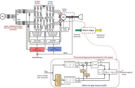
2. LCI Systems for Synchronous Motors

2.1. Operating Range of LCIs in O&G Industry

Figure 2 summarizes the operational application envelope of LCIs and VSIs in upstream O&G industry, depending on the motor speed and the corresponding power range [11]:
  • Liquefied Natural Gas plants, with a speed between 3000 and 3600 rpm, and a power range between 10 and 80 MW.
  • Pipeline recompression and decompression, with speed between 4000 and 8000 rpm, and a power range between 10 and 40 MW.
  • Storage recompression and decompression, with speed between 8000 and 18,000 rpm, and a power range between 15 and 20 MW.
  • Gas refrigeration with a speed between 15,000 and 20,000 rpm, and a power range between 0.75 and 4 MW.
There is a large overlap area where both LCIs and VSIs can be utilized without substantial differentiation in terms of their benefits. The design engineers use their project-specific requirements (such as performance, cost, reliability, lead time, etc.) to select the type of VFD which is suitable for their needs [12]. In some cases, selections are based on their company agreements with certain preferred VFD suppliers. Such contracts can cover cost-reduction approaches because of the pre-agreed factory acceptance tests and documentation flowcharts. Synchronous machines with field windings tend to be preferred in very high-power applications because the rotor current is supplied separately through a rotating rectifier, resulting in overall reduced losses [13].

2.2. Engineering Challenges of LCIs

2.2.1. Input Power Quality

The quality of power at the point of common coupling (PCC) remains a concern in large power VFD application in the O&G facilities. The IEEE-519 standard is usually followed during the design of large VFD [14]. Therefore, multi-secondary transformers, combined to multi-pulse rectifier systems are often utilized. This standard is mainly providing guidelines for steady-state requirements on the input power quality. However, in some weak islanded systems such as in oil platforms, the quality of power affecting VFDs is due to transient events impacting the voltage at the terminal of the VFD input transformer. Such transient events include the following: (i) circuit breaker closure and restrike that can induce resonance phenomena in the transformer, potentially leading to transformer insulating breakdown; and (ii) disconnect switch operation which can result in transformer insulation breakdown due to multiple reflections and refractions of traveling waves. Such overvoltage can exceed the basic insulation level (BIL) of transformers, which can be as high as 150 kV.

2.2.2. Machine Compatibility: Induction vs. Synchronous Machines

The windings of the AC motors should be able to survive significant high-voltage spikes, and high dv / dt caused by the VFD output waveforms. Such spikes can potentially create partial discharges, which can possibly damage the winding insulation [15]. VFDs are also known for inducing bearing currents failures due to unwanted common-mode voltages and currents that are inherent to VFDs topologies [16].
LCIs are suitable to operate with synchronous machines since thyristor commutation needs a voltage assistance. Such voltage assistance is provided by the back electromagnetic force (EMF) of the synchronous motor. To utilize LCI with induction motors, additional passive commutation components are needed to assist the thyristor operation, which increase the system complexity and thereby reduce LCI reliability. As a result, LCIs are preferred for driving synchronous machines, while VSIs are preferred for induction machines for the simplicity of their implementation [17].

2.2.3. Reliability

Even though the insertion of a VFD in the energy conversion shaft has provided noticeable benefits in term of overall system performance, it has also created a new single-point of failure, which has decreased the overall system reliability. High-reliability is one of the key requirements that is reducing the high penetration of VFD in certain applications, such as in the oil and gas industry. Several VFD topologies have been proposed, and some of them have been adopted by the industry to supply high-power to the motor with reasonable reliability [9]. In general, VFD topologies are built with series connection of power switches with their control boards to handle the medium voltage needed in high-power applications; and some of them require series or parallel connected power electronic building blocks to supply high-power, as described in the next subsection.
Increasing the number of power device components has reduced the reliability of VFDs in general. However, certain high-power VFD topologies offer the possibility of N + 1 redundancy, which increases the over system cost. Consequently, a trade-off analysis between cost, performance and reliability is carried out per project at the design stage. The modularity of LCI systems built around identical six-pulse rectifier and six-pulse inverter building blocks had enable the VFD to easily be scaled-up for high-power applications, while maintaining a high-reliability due to built-in redundancies at the component level, as well as at the module level. Therefore, LCI systems have proven reliability records since they were introduced decades ago to industry.

2.2.4. Torsional Excitation and Low-Torque Ripple

Rotating shafts models are constructed by the interconnection of multiple inertias through stiffness constants and viscous damping devices. Therefore, they form a multi-resonant system with Eigen frequencies that might be excited. A shaft being excited by externally applied stimulus forces be subject to accelerated fatigue or breakdown [3], possibly impacting production output in industry. All VFD topologies supply voltage and current harmonics that are mixed in the motor’s air-gap to generate pulsating torque components. Some of these components might have relatively high magnitudes [18]. If some of these pulsating torque components have frequencies that are located in the vicinity of the shaft natural frequencies, they might increase the shear stress on the shaft material beyond its design value. Consequently, VFDs are seeing as a potential threat to the shaft integrity.
To prevent shaft failure due to their Eigenmode excitation, VFDs should be designed to generate motor air-gap torque components with low magnitudes at shaft natural frequencies. Specifically, torque harmonics should be located far away from the first resonance mode of the shaft which has the lowest natural frequency at low [3,4].

2.3. LCI System Configurations

Large gas-turbine generator systems are often driven by Direct-On-Line motor with hydraulic coupling, or by a LCI to accelerate the gas turbine startup. Because LCI systems offer high-reliability records, they are widely used in high-power and low-speed applications for system start-up.
To address the input power quality challenges, several six-pulse building blocks are stacked on the rectifier side, which requires a multi-secondary input transformer. As consequence, the grid current has a higher number of pulses, leading to current harmonics with substantial high-frequencies and low magnitudes [18]. Moreover, when large power is required, synchronous machines with multiple three-phase windings are housed in the same stator. Consequently, several 6-pulse building blocks are also stacked on the inverter sides. Figure 3 shows numerous configurations of the LCI topology. In Figure 3a, a 12/12-pulse configuration for a six-phase synchronous motor is shown; and Figure 3c shows a 24/12-pulse configuration for the same machine. In more generic term, LCIs are always arranged with a p/q-pulse configuration as shown in Figure 3b.

2.4. Advantages and Drawbacks of LCIs

Modularity: LCIs are modular power conversion structures, which can be easily stacked to achieve desired electrical or mechanical harmonic performance on the grid or on the motor side. The converter is built around 6-pulse thyristor modules, both on the rectifier and inverter sides [19].
The same power devices and firing cards are often used, leading to an easy spare part strategy, mainly for upstream O&G facilities located offshore or in remote geographical areas which are very challenging for logistics and transportation locations.
Motor speed: A motor driven by LCI can hardly exceed 120 Hz fundamental frequency, because of the commutation requirements of thyristor devices. Therefore, LCIs are not utilized in high-speed motor applications. For compressor applications for example, a gearbox is always required to adapt the motor’s low-speed to compressors’ high-speed [12].
Input power quality: LCIs are often built such that they fulfill international standards often used in project specifications at its point of common coupling. In some cases, an input harmonic filter is required, leading to an increased complexity and size which are undesired in offshore platforms [19].
Reliability: Based on a very large operational record, LCIs are one of the most reliable high-power converter topologies in industry today. Thyristor devices are well-known and their firing and protection schemes are mature in today’s LCIs [16].
Torque harmonics: Because of well-known characteristics of their torque harmonics, this topology suffers with a high-torque ripple, which might excite shaft’s Eigen frequencies.
Torsional vibration control and damping: Because of their easy control methods, a torque resonance damping control function can be easily integrated to any LCI, with minor changes, both on the motor and grid sides. Particularly for weak power systems. Such function can substantially reduce the risk to excite gas-turbine generators torsional natural frequencies, regardless of their origin [3,9].

3. Instantaneous Electromagnetic Torque Harmonics in LCI Systems

3.1. Assumptions

For sake of simplicity with minor impacts to the overall results, the following assumptions are made. The LCI has a p/q-pulse configuration, and the main notations are adjusted for grid and motor sides respectively. The grid side is a three-phase system with, but its per unit values are neglected; therefore, the grid side overlap angle is neglected. Similarly, the synchronous motor model is assumed to be a back-electromotive force (EMF), behind a series R m ,   L m impedance with negligible per unit values. Consequently, the inverter side overlap angle is also not taken into account. The resistance of the DC coil is negligible; therefore, only the DC link is a pure inductive energy storage tank.
The investigations presented in this paper are limited to the effects of the VFD on the electromagnetic torque resulting from the fluctuation of the magnetomotive force only. The analysis is performed in steady state from the electrical parameters point of view. In such conditions, it is assumed that the field windings are supplied by a constant steady state current. Thus, the type of rotor has no impact on the electromagnetic air-gap torque. Consequently, the results discussed in this paper are valid both for field winding machines and for synchronous machines with permanent magnet rotor.
In general, the electromagnetic pulsating torque components result from the electromagnetic phenomenon in the machine, which is visible through the magnetomotive force. They originate from two sources: machine’s construction-induced torque ripples (reluctance torques, commutation torques and cogging torques) and power-supply-induced torque ripples, which depends on the quality of the power being supplied to the motor.
The paper investigation is from the industrial operational point of view (as specified in the API standards [5,6,7,8]), and not from the machine design point of view. With such approach, it is assumed that the machine was fully designed to minimize all machine construction induced pulsating torque components. Therefore, this paper only investigates the electromagnetic torque resultant from the imperfection of the power quality supplied to the motor [20]. The quality of the power is dependent on the quality of the current supplied to the motor by the LCI system. The LCI system is inherently supplying a non-sinusoidal current to the machine, due to the commutation of the thyristors.
From the analytical point of view, it is to be noticed that all motor construction induced torque components are dependents on the machine speeds and can be classified as baseband harmonics, with frequencies proportional to the stator current and motor poles (i.e., motor speed), and magnitudes dependent on the machine construction [21].

3.2. LCI Current Harmonic Performance

LCI electrical harmonics can be analyzed by superposing individual effects of the grid and motor side voltages v g ( t ) and v m ( t ) , as shown in Figure 4. The machine voltage corresponds to its back EMF. It is usually reasonable to assume that the grid voltage and motor back EMF are harmonic free.
A generic formulation of a current harmonic i M g i N g i ( t ) on the grid side is given by the following:
i M g i N g i ( t ) = I M g i N g i cos ( M g i ω g t + N g i ω m t + θ M g i N g i i )
where I M g i N g i and θ M g i N g i i are respectively the current harmonic magnitude and phase; ω g and ω m are the grid and motor frequencies; and M g i and N g i are integers given by the following:
M g i = m g i p ± 1 ,   with   m g i = 0 ,   ± 1 ,   ± 2 ,   ± 3
N g i = n g i q ,   with   n g i = 0 ,   1 ,   2 ,   3
Similar expressions are derived for the motor side current harmonic performance as shown in Equations (4) and (5):
i M m i N m i ( t ) = I M m i N m i cos ( M m i ω g t + N m i ω m t + θ M m i N m i i )
where I M m i N m i and θ M m i N m i i are respectively the current harmonic magnitude and phase; ω g and ω m are the grid and motor frequencies; and M m i and N m i are integers given by the following:
M m i = m g i p ± 1 ,   with   m m i = 0 ,   1 ,   2 ,   3
N m i = n m i q ± 1 ,   with   n m i = 0 ,   ± 1 ,   ± 2 ,   ± 3

3.3. LCI Current Harmonic Performance

The electromagnetic torque in the motor’s air gap is produced by the interaction of the motor stator flux derived from the back EMF and the current produced by the LCI as shown in Equations (7) and (8). The flux is the time integral of the back EM. It is usually convenient to express the torque in the stationary orthogonal reference frame, 0 α β , in order to properly capture the effects of frequency superposition in the air gap.
t e ( t ) = 3 2 P 2 ( ψ α   i β ψ β   i α )
ψ a b c = ( v m a b c Z s i m a b c ) d t v m a b c d t
where t e ( t ) is a time-dependent torque in the machine’s air gap, Z s is the machine impedance, P is the machine’s number of poles; ( ψ α ,   ψ β ) and ( i α ,   i β ) are stator flux and current in α β -coordinates.
The motor’s air-gap torque harmonic components when supplied by a p/q-pulse LCI can be expressed as follows [9]:
t e h ( t ) = T e h cos ( ω h t + θ h )
T e h = 3 2 P 2 V 01 ω m I m m i n m i
ω h = m m i p ω g + n m i q ω m
θ h = θ m m i n m i i ε n m i θ 01 v
where V 01 is the magnitude of the fundamental of the motor’s back EMF, and θ 01 v is its phase; ε n m i = 1 for a positive sequence harmonic, and ε n m i = 1 for a negative sequence harmonic. Usually, torque frequencies are plotted in a Campbell diagram to find operational speeds where torsional excitation may occur. The instantaneous expression of the air-gap electromagnetic torque is summarized as follows:
t e ( t ) = T D C + n = 1 T e 0 , n q cos ( n q ω 0 t + θ 0 , n q ) + m = 1 n = 0 T e , m p , n q cos ( ( m p ω g ± n q ω 0 ) t + θ m p , n q )
T D C = λ 0   m = 0 n = 1 sin ( n 2 π 3 ) V m n I m n m p ω g + n q ω 0 cos θ m n i
λ 0 = 3 2 P 2 2 3 ;   and   T D C λ 0   n = 1 sin ( n 2 π 3 ) V 01 I 0 n ω 0 cos θ 0 n i

3.4. Torque Harmonic Families for a 6/6-Pulse LCI System

The instantaneous expression of the electromagnetic torque in the air gap of a synchronous motor supplied by a 6/6-pulse LCI system is shown in Equation (16). For sake of simplicity, the DC torque is not shown. The three harmonic families are summarized in Figure 5 and Figure 6. All baseband harmonics are integer multiple of 6, because of the 6-pulse inverter on the motor side; and all gridband harmonics are also integer multiple of 6, because of the 6-pulse rectifier on the grid side. Finally, there are sideband harmonics around multiple of 6 times the grid frequency surrounded by integer multiple of 6 times the motor current frequency.
t e 6 / 6 ( t ) = T D C + n = 1 T e 0 , n q cos ( 6 n ω 0 t + θ 0 , 6 n ) + m = 1 n = 0 T e , 6 m , 6 n cos ( ( 6 m ω g ± 6 n ω 0 ) t + θ 6 m , 6 n )

3.5. Torque Harmonic Families for a 12/12-Pulse LCI System

Likewise, the instantaneous expression of the electromagnetic torque in the air gap of a synchronous motor supplied by a 12/12-pulse LCI system is shown in Equation (17), and harmonic families are summarized in Figure 7 and Figure 8. In this case, all harmonics odd multiple of 6 are eliminated. The only remaining ones are all integer multiple of 12.
t e 12 / 12 ( t ) = T D C + n = 1 T e 0 , 12 n cos ( 12 n ω 0 t + θ 0 , 12 n ) + m = 1 n = 0 T e , 12 m , 12 n cos ( ( 12 m ω g ± 12 n ω 0 ) t + θ 12 m , 12 n )

3.6. Torque Harmonic Families for a 24/24-Pulse LCI System

Consistent with the previous results, the instantaneous expression of the electromagnetic torque in the air gap of a synchronous motor supplied by a 24/24-pulse LCI system is shown in Equation (18) and harmonic families are summarized in Figure 9 and Figure 10. Only harmonics which are integer multiples of 24 are present; all other harmonic components were eliminated as a result of transformer phase-shift both in grid and motor sides.
Because of the reduced number of harmonics as both side number of pulses increase, it is obvious that the higher the pulses on the grid side, the lower its current total harmonic distortion. Similar conclusions can be drawn on the motor side, with respect to the inverter side number of pulses.
t e 24 / 24 ( t ) = T D C + n = 1 T e 0 , 24 n cos ( 24 n ω 0 t + θ 0 , 24 n ) + m = 1 n = 0 T e , 24 m , 24 n cos ( ( 24 m ω g ± 24 n ω 0 ) t + θ 24 m , 24 n )

3.7. Campbell Diagrams of LCI Systems

The theoretical results developed in the previous subsections are grouped in the respective Campbell diagrams shown in Figure 11. They highlight the positive impact of high-pulse order of LCIs when supplying a motor which is driving a shaft with risk of exciting its natural frequencies. It is to be noted that the torque frequency limits of the y-axis of these diagrams were kept identical to ease the understanding of the impact of the rectifier and inverter number of pulses. The cleaner the diagram, the lower the risk of exciting shaft Eigenmodes.

4. Numerical Validation of the Theoretical Results

All investigated systems are simulated using Matlab/Simulink software. For each investigated case, the LCI model and its control strategy, as well as the synchronous motor and a single inertia load are implemented in Simulink environment. Simulations are run till the motor reaches its steady state, and then relevant state variables are recorded to the workspace. The recorded state variables are then post-processed for visualization and analyzed in time and frequency domains. The validation method used is described in detail in Section 4.2.

4.1. Simulated Systems

The parameters shown in Table 1 were used to simulate a 6/6-pulse and a 12/12-pulse LCI systems. Simplified electric diagrams of the simulated systems are shown in Figure 12 and Figure 13 respectively, with the respective grid and motor side control functionalities. The firing angles of each power stage are synchronized to their respective voltages.
The grid is replaced by a set of three-phase voltages supplying the isolation transformers. In both systems, three- and six-phase synchronous motors are respectively utilized as electric load, driving a mechanical load. The six-phase synchronous motor is a double three phases winding systems which are electrically phase-shifted by 30 degrees.

4.2. Validation Method

4.2.1. Principle of Validation

Each investigated system was simulated with the fundamental frequency varying from 5 to 50 Hz, with a step of 5 Hz, while the grid fundamental frequency was constant at 50 Hz. For a given operating point, the system is simulated until it reaches its steady state, then the voltages, currents and air-gap electromagnetic torque waveforms are recorded at 50 kHz sampling rate for the time domain analysis. The results are processed as follows: (i) the recorded three-phase currents and voltages are Park transformed to the stationary and orthogonal coordinates; (ii) then, the stator flux is calculated as a time integral of the transformed voltage; and finally, (iii) the torque is reconstructed according to the equations developed in this paper.

4.2.2. Frequency Domain Validation

For frequency domain analysis, a Fast Fourier Transformation (FFT) with a 1 Hz resolution and an even window length is applied to the recorded (simulated) and reconstructed (calculated) electromagnetic torque waveforms. The magnitudes and frequencies of the simulated and calculated results are then compared. Finally, the locations of the torque and current harmonic frequencies are compared in order to validate the accuracy of the results. Finally, the instantaneous electromagnetic torque is reconstructed from the dominant components of the power spectrum density of the torque spectrum, which coincide with the dominant calculated torque components located at the predicted frequencies.

4.2.3. Confirmation of the Robustness of the Results

The validation method described in this section is implemented on both system configurations at multiple operating points, i.e., different fundamental frequencies. The summary is outlined in Campbell diagrams, in which simulated torque frequencies are superposed to the predicted Campbell lines to confirm the accuracy and robustness of the proposed relationships.

4.3. Selected Simulation Results of a 6/6-Pulse LCI System

4.3.1. Simulation Results in Time and Frequency Domains

In this subsection, the results of the specific operating point with a fundamental frequency of 40 Hz are discussed. In Figure 14a–d, the grid voltage and current, as well as their respective spectra, are shown.
The grid voltage is a pure sinewave; therefore, its spectrum contains only the fundamental component as shown in Figure 14b. It should be highlighted that only secondary side state variables are shown. In that case, the rectifier side firing angles are synchronized to the transformer secondary voltages.
The current spectrum contains baseband and sideband harmonics. It is to be noted that, in the grid side analysis, baseband harmonic family has frequencies that are integer multiple of the grid frequency and are all in the form of negative and positive sequence harmonics. Sideband harmonic families are grid side harmonics with frequencies located around an integer multiple the motor operational frequency. This distinction is to be made to avoid misunderstanding of the harmonic concepts and harmonic families.
For illustrative purposes, the DC-link current in time and frequency domains is shown in Figure 14e,f, and grid active and reactive powers are shown Figure 14g, while the motor active and reactive power are shown in Figure 14h.
In Figure 15a–d, the motor voltage and current, as well as their respective spectra, are shown. The motor voltage is not a pure sinewave. These spectra contain baseband, gridband and sideband harmonics. Because the voltage spectrum is the line-to-line voltage, it does not contain gridband harmonics, which are common-mode harmonics. It is to be noted in the motor side analysis that the baseband frequencies are integer multiple of the motor frequency and are all in the form of negative and positive sequence harmonics. Gridband harmonic families are motor side harmonics with frequencies which are integer multiple the motor operational frequency. Moreover, sideband harmonic families are harmonic components located around an integer multiple of the grid frequency. Moreover, the shaft speed is constant, as shown in Figure 15g, which shows that data were recorded when the motor reached its steady state. Therefore, its spectrum shows a single DC component, as illustrated in Figure 15f.
The simulated instantaneous electromagnetic torque is shown Figure 15e, and its spectrum is shown in Figure 15f.
Because the torque was expressed in α β reference frame, motor stator currents are also expressed in α β coordinates as shown in Figure 16a, and their spectra are shown in Figure 16b. The current space vector is illustrated in Figure 16c. The stator voltages and their respective spectra in α β , as well as the corresponding space vector, are shown in Figure 16d,f. The time integral of the stator voltage is calculated to derive the stator flux as shown in Figure 16g,i. These are the state variables that were utilized to determine the instantaneous motor air-gap torque shown in Figure 15e. A more precise analysis of the harmonic location in the frequency domain is given in Section 4.3.2.

4.3.2. Detailed Analysis of Harmonic Families

In this section, a detailed analysis of harmonic families is performed based on the simulated results of a 6/6-pulse LCI system operating at f 0 = 40 Hz. It is to be noted that the grid voltage is f g = 40 Hz. The spectra are shown in Figure 15f and Figure 16b and magnified respectively in Figure 17a,b, to illustrate the exact location of each harmonic and its family, based on the actual value of its frequency. Families of generated harmonics are given based on the analytical expression of the frequencies developed in this paper. Moreover, for a given double set of current harmonics highlighted in Figure 17a, the single torque harmonics they are generating in the air gap are shown in Figure 17b, with identical color. It is to be noted that each torque harmonic component is created by two current harmonic components.
Detailed analysis of stator current harmonic families: The following harmonics are identified in Figure 17a; the values and location are given in the form ( M i ,   N i ) .
  • Baseband harmonic family of stator current are located at ( 0 ,   N i ) : (i) 200   H z ( 0 ,   5 ) and 280 ( 0 ,   7 ) ; (ii) 440   H z ( 0 , 11 ) and 520 ( 0 , 13 ) ; (iii) 680   H z ( 0 , 17 ) and 760 ( 0 , 19 ) .
  • Sideband harmonic family of stator current located around 1 × 6 f g are given in the form of ( 6 ,   N i ) : (i) 20   H z ( 6 , 7 ) and 100   H z ( 6 , 5 ) ; (ii) 140   H z ( 6 , 11 ) and 220   H z ( 6 , 13 ) ; (iii) 260   H z ( 6 , 1 ) and 340   H z ( 6 , 1 ) ; (iv) 380   H z ( 6 , 17 ) and 460   H z ( 6 , 19 ) ; (v) 500   H z ( 6 , 5 ) and 580   H z ( 6 , 7 ) ; (vi) 740   H z ( 6 , 11 ) and 820   H z ( 6 , 13 ) ; (vii) 980   H z ( 6 , 17 ) and 1060   H z ( 6 , 19 ) .
  • Sideband harmonic family of stator current located around 2 × 6 f g are given in the form of ( 12 ,   N i ) : (i) 80   H z ( 12 , 13 ) and 160   H z ( 12 , 11 ) ; (ii) 320   H z ( 12 , 7 ) and 400   H z ( 12 , 5 ) ; (iii) 560   H z ( 12 , 1 ) and 640   H z ( 12 , 1 ) ; (iv) 800   H z ( 12 , 5 ) and 880   H z ( 12 , 7 ) ; (v) 1040   H z ( 12 , 11 ) and 1120   H z ( 12 , 13 ) .
  • Sideband harmonic family of stator current located around 3 × 6 f g are given in the form of ( 18 ,   N i ) : (i) 860   H z ( 18 , 1 ) and 940   H z ( 18 , 1 ) .
Detailed analysis of air-gap torque harmonic families generated by the previously identified current harmonic families: The following torque harmonics are identified in Figure 17b, the values and location are given in the form ( m , n ) .
  • Baseband harmonic family of torque current are located at ( 0 , N i ± 1 ) : (i) 240   H z ( 0 , 6 ) ; (ii) 480   H z ( 0 , 12 ) ; (iii) 720   H z ( 0 , 18 ) .
  • Sideband harmonic family of torque current located around 1 × 6 f g are given in the form of ( 6 , N i ± 1 ) : (i) 60   H z ( 6 , 6 ) ; (ii) 180   H z ( 6 , 12 ) ; (iii) 300   H z ( 6 , 0 ) ; (iv) 420   H z ( 6 , 18 ) ; (v) 540   H z ( 6 , 6 ) ; (vi) 780   H z ( 6 , 12 ) ; (vii) 1020   H z ( 6 , 18 ) .
  • Sideband harmonic family of torque current located 2 × 6 f g are given in the form of ( 12 , N i ± 1 ) : (i) 120   H z ( 12 , 18 ) ; (ii) 360   H z ( 12 , 6 ) ; (iii) 600   H z ( 12 , 0 ) ; (iv) 840   H z ( 12 , 6 ) ; (v) 1080   H z ( 12 , 12 ) .
  • Sideband harmonic family of stator current located around 3 × 6 f g are given in the form of ( 18 , N i ± 1 ) : (i) 900   H z ( 18 , 0 ) .
This detailed analysis of the simulation results confirms the accuracy of the theoretical analysis proposed in this paper.

4.3.3. Reconstruction of the Instantaneous Electromagnetic Air-Gap Torque Waveform

Based on the previous detailed harmonic families’ analysis, the instantaneous electromagnetic torque was reconstructed to verify the relationships proposed in this paper. Figure 18a shows the “filtered” current based on the dominant harmonic level per the principle proposed in this paper, and Figure 18b shows the reconstructed instantaneous electromagnetic torque. These waveforms show an accurate superposition of both simulated and calculated results.

4.3.4. Campbell Diagram and Relevant Air-Gap Torque Harmonic Families and Their Magnitude

The results of all simulated operating points were summarized in a Campbell diagram, where predicted location of the torque harmonic components in the frequency domain are represented by solid lines. The specific case when f o = 40 Hz is clearly highlighted, with their respective values of the ( m , n ) set of parameters, as shown in Figure 19a. Relevant harmonic families are shown in Figure 19b. Moreover, the magnitude of each harmonic component in a given harmonic family is shown in Figure 19c.

4.4. Selected Simulation Results of a 12/12-Pulse LCI System

4.4.1. 12/12-Pulse LCI System Operation at 40 Hz

Sample simulation results of the 12/12-pulse LCI system are summarized in this subsection in a similar way as the results of a 6/6 LCI system presented in the previous subsection. The same operating point at f o = 40 Hz was chosen for specific discussion in order to ease the analysis and to confirm the robustness of the proposed relationships.
In Figure 20a–d, the grid voltage and current, as well as their respective spectra, are shown. Only phase “a” voltages and currents of both three-phase systems are shown. The voltages are 30-degree phase-shifted, which also produce currents that are also 30-degree phase-shifted. Voltage and current spectra of both systems are identical; only their phases are different and are not shown for sake of simplicity. The grid voltages are pure sinewaves; therefore, their spectrum contains only the fundamental component as shown in Figure 20b. However, the current spectrum contains baseband and sideband harmonics. As previously discussed, in the grid side analysis, baseband harmonic family has frequencies that are integer multiple of the grid frequency and are all in the form of negative and positive sequence harmonics. Sideband harmonic families are grid side harmonics with frequencies located around an integer multiple the motor operational frequency. This distinction is to be made to avoid misunderstanding of the harmonic concepts and harmonic families.
For illustrative purposes, the DC-link current in the time and frequency domains is shown in Figure 20e,f, and grid active and reactive powers are shown Figure 20g, while the motor active and reactive power are shown in Figure 20h. In Figure 21a–d, the motor voltages and currents of respective phase “a”, as well as their respective spectra, are shown. The motor voltages are not pure sinewaves. These spectra contain baseband, gridband and sideband harmonics.
Because the voltage spectrum is the line-to-line voltage, it does not contain gridband harmonics, which are common-mode harmonics. It is to be noted in the motor side analysis that the baseband frequencies are integer multiple of the motor frequency and are all in the form of negative and positive sequence harmonics. Gridband harmonic families are motor side harmonics with frequencies which are integer multiple the motor operational frequency. Moreover, sideband harmonic families are harmonic components located around an integer multiple of the grid frequency. Moreover, the shaft speed is constant as shown in Figure 21g, which shows that data were recorded when the motor reached its steady state. Therefore, its spectrum shows a single DC component, as illustrated in Figure 21h.
The simulated instantaneous electromagnetic torque is shown Figure 21e, and its spectrum is shown in Figure 21f. Because the torque was expressed in an α β reference frame, motor stator currents are also expressed in α β coordinates as shown in Figure 22a, and their spectra are shown in Figure 22b. The current space vector is illustrated in Figure 22c. The stator voltages and their respective spectra in α β , as well as the corresponding space vector, are shown in Figure 22d–f. The time integral of the stator voltage is calculated to derive the stator flux as shown in Figure 22g–i. These are the state variables that were utilized to determine the instantaneous motor air-gap torque shown in Figure 21e. A more precise analysis of the harmonic location in the frequency domain is given in Section 4.4.2.

4.4.2. Detailed Analysis of Harmonic Families

In this section, a detailed analysis of harmonic families is performed based on the simulated results of a 12/12-pulse LCI system operating at f 0 = 40 Hz. It is to be noted that the grid voltage is f g = 40 Hz. The spectra shown in Figure 21d,f are magnified and respectively shown in Figure 23a,b, to illustrate exact location of each harmonic and its family, based on the actual value of its frequency.
Families of generated harmonics are given based on the analytical expression of the frequencies developed in this paper. Moreover, for a given double set of current harmonics highlighted in Figure 23a, the single torque harmonics they are generating in the air gap are shown in Figure 23b, with identical color. It is to be noted that each torque harmonic component is created by two current harmonic components. Detailed analysis of stator current harmonic families: The following harmonics are identified in Figure 23a; the values and location are given in the form ( M i ,   N i ) .
  • Baseband harmonic family of stator current are located at ( 0 , N i ) : (i) 440   H z ( 0 , 11 ) and 520   H z ( 0 , 13 ) ; (ii) 920   H z ( 0 , 23 ) and 1000   H z ( 0 , 25 ) ; (iii) 1400   H z ( 0 , 35 ) and 1480   H z ( 0 , 37 ) .
  • Sideband harmonic family of stator current located around 1 × 12 f g are given in the form of ( 12 , N i ) : (i) 80   H z ( 12 , 13 ) and 160   H z ( 12 , 11 ) ; (ii) 320   H z ( 12 , 23 ) and 400   H z ( 12 , 25 ) ; (iii) 560   H z ( 12 , 1 ) and 640   H z ( 12 , 1 ) .
  • Sideband harmonic family of stator current located 2 × 12 f g are given in the form of ( 24 , N i ) : (i) 200   H z ( 24 , 25 ) and 280   H z ( 24 , 23 ) ; (ii) 680   H z ( 24 , 13 ) and 760   H z ( 24 , 11 ) ; (iii) 1160   H z ( 24 , 1 ) and 1240   H z ( 24 , 1 ) .
When compared to the detailed spectrum analysis of a 6/6-pulse LCI system, the simulation results of a 12/12-puls LCI system clearly show that only baseband harmonics which are multiple of twelve remain. Moreover, sideband harmonics are now located around multiple of twelve times the grid frequency remain. All other are cancelled or have negligible magnitudes (irrelevant for the purpose of this paper).
Detailed analysis of air-gap torque harmonic families generated by the previously identified current harmonic families: The following torque harmonics are identified in Figure 23b; the values and location are given in the form ( m , n ) .
  • Baseband harmonic family of torque current are located at ( 0 , N i ± 1 ) : (i) 480   H z ( 0 , 12 ) ; (ii) 960   H z ( 0 , 24 ) ; (iii) 1440   H z ( 0 , 36 ) .
  • Sideband harmonic family of torque current located around 1 × 12 f g are given in the form of ( 12 , N i ± 1 ) : (i) 120   H z ( 12 , 12 ) ; (ii) 360   H z ( 12 , 24 ) ; (iii) 600   H z ( 12 , 0 ) .
  • Sideband harmonic family of torque current located 2 × 12 f g are given in the form of ( 24 , N i ± 1 ) : (i) 240   H z ( 24 , 24 ) ; (ii) 720   H z ( 24 , 12 ) ; (iii) 1200   H z ( 24 , 0 ) .
Frequencies of torque harmonic families are consistent with the current harmonics that have created them. This detailed analysis of the simulation results also confirms the accuracy of the theoretical analysis proposed in this paper.

4.4.3. Reconstruction of the Instantaneous Air-Gap Torque Waveform

Based on the previous detailed harmonic families’ analysis, the instantaneous electromagnetic torque was reconstructed to verify the relationships proposed in this paper. Figure 24a shows the “filtered” current based on the dominant harmonic level per the principle proposed in this paper, and Figure 24b shows the reconstructed instantaneous electromagnetic torque. These waveforms show an accurate superposition of both simulated and calculated results.

4.4.4. Summary: Campbell Diagram and Relevant Air-Gap Torque Harmonic Families and Their Magnitudes

The results of all simulated operating points were summarized in a Campbell diagram, where predicted location of the torque harmonic components in the frequency domain are represented by solid lines. The specific case when f o = 40 Hz is clearly highlighted, with their respective values of the ( m , n ) set of parameters, as shown in Figure 25a. Moreover, the relevant harmonic families are shown in Figure 25b, and the magnitude of each harmonic component in a given harmonic family is shown in Figure 25c.
The Campbell diagram of the 12/12-pulse LCI system has fewer lines, which reduces the risk of torsional excitation of the driven shaft.

5. Conclusions

This paper proposed analytical expressions of the instantaneous electromagnetic torque in the air gap of a synchronous motor supplied by LCI systems. These relationships are written based on voltage and current harmonic components in the stationary orthogonal reference frame. They are developed to fulfil international standard requirements to perform accurate torsional analysis. Simulation results of a 6/6-pulse and 12/12-pulse systems, as well as the detailed location of their current harmonic components, which are correlated to torque harmonic locations in the frequency domain confirm the accuracy of the proposed expressions.
Even though the finite-element methods might be considered to be an alternative approach to derive electromagnetic air-gap torque of a motor supplied by LCIs, such methods are very challenging to extract insightful information for the purpose of performing torsional analysis as required by the API standards [5,6,7,8]. Therefore, they have not been explored in this paper.

Author Contributions

Conceptualization and overall paper organization, G.E. and J.S.-M.: theoretical and numerical validation methodologies, and numerical simulations and simulation data processing, P.M.L. and G.E.; results analysis, G.E., J.S.-M. and P.M.L.; writing—original draft preparation an writing, G.E. and J.S.-M.; review and editing, P.M.L.; supervision, F.S.-H. and I.F. All authors have read and agreed to the published version of the manuscript.

Funding

This research received no external funding.

Conflicts of Interest

The authors declare no conflict of interest.

References

  1. Campbell, J.M. The Basic Principle. In Gas Conditioning and Processing, 8th ed.; John Campbell and Company: Norman, OK, USA, February 2004; Volume 1. [Google Scholar]
  2. Campbell, J.M. The Equipment Modules. In Gas Conditioning and Processing, 8th ed.; John Campbell and Company: Norman, OK, USA, February 2004; Volume 2. [Google Scholar]
  3. Hutten, V.; Zurowski, R.M.; Hilsher, M. Torsional interharmonic interaction study of 75 MW direct-driven VSDS motor compressor trains for LNG duty. In Proceedings of the 37th Turbomachery and Pump Symposia, College Station, TX, USA, 8–11 September 2008; pp. 57–66. [Google Scholar]
  4. Schramm, S.; Sihler, C.; Song-Manguelle, J.; Rotondo, P. Damping Torsional Interharmonic Effects of Large Drives. IEEE Trans. Power Electron. 2010, 25, 1090–1098. [Google Scholar] [CrossRef]
  5. API. API Standard 617, Axial and Centrifugal Compressors and Expander-Compressors, 8th ed.; API: Englewood, CO, USA, 2016. [Google Scholar]
  6. API. API Standard 672, Packaged, Integrally Geared Centrifugal Air Compressors for Petroleum, Chemical, and Gas Industry Services, 5th ed.; API: Englewood, CO, USA, August 2019. [Google Scholar]
  7. API. API Standard 673, Centrifugal Fans for Petroleum, Chemical and Gas Industry Services, 3rd ed.; API: Englewood, CO, USA, December 2014. [Google Scholar]
  8. API. API Standard 684, Paragraphs Rotodynamic Tutorial: Lateral Critical Speeds, Unbalance Response, Stability, Train Torsional, and Rotor Balancing, 2nd ed.; API Recommended Practice 684; API: Englewood, CO, USA, August 2005. [Google Scholar]
  9. Toliyat, H.A.; Nandi, S.; Choi, S.; Meshgin-Kelk, H. Electric Machines: Modelling, Condition Monitoring, and Fault Diagnosis; CRC Press, Taylor and Francis Group: Boca Raton, FL, USA, 2013; pp. 83–85. [Google Scholar]
  10. Rotondo, P.; Andreao, D.; Famoli, S.; Jörg, P.; Lenzi, A.; Hattenbach, T.; Fioravanti, D.; de Franciscis, S. Combined Torsional and Electromagnetic Analysis of an LNG Compression Train with Variable Speed Drive System. In Proceedings of the 38th Turbo Machinery Symposium, College Station, TX, USA, 14–17 September 2009; pp. 93–102. [Google Scholar]
  11. Song-Manguelle, J.; Sihler, C.; Schramm, S. A General Approach of Damping Torsional Resonance Modes in Multi-megawatt Applications. IEEE Trans. Ind. Appl. 2011, 47, 1390–1399. [Google Scholar] [CrossRef]
  12. Baccani, R.; Zhang, R.; Toma, T.; Iuretig, A.; Perna, M. Electric Systems for High Power Compressor Trains in Oil and Gas Applications—System Design, Validation Approach and Performance. In Proceedings of the 36th Turbo Machinery Symposium, College Station, TX, USA, 11–13 September 2007; pp. 61–68. [Google Scholar]
  13. Lipo, T.A. Introduction to AC Machine Design; Series on Power Engineering; Wiley-IEEE Press: Hoboken, NJ, USA, 2017. [Google Scholar]
  14. IEEE. Std 519-2014 Recommended Practice and Requirements for Harmonic Control in Electric Power Systems; IEEE: Piscataway, NJ, USA, 2014. [Google Scholar]
  15. Mohamadian, S.; Castellan, S.; Tessarolo, A.; Ferrari, G.; Shoulaie, A. An Algebraic Algorithm for Motor Voltage Waveform Prediction in Dual-LCI Drives with Interconnected DC-Links. IEEE Trans. Energy Convers. 2016, 31, 506–519. [Google Scholar] [CrossRef]
  16. Muetze, A.; Binder, A. Practical Rules for Assessment of Inverter-Induced Bearing Currents in Inverter-Fed AC Motors up to 500 Kw. IEEE Trans. Ind. Electron. 2007, 54, 1614–1622. [Google Scholar] [CrossRef]
  17. Mon-Nzongo, D.; Ekemb, G.; Song-Manguelle, J. LCIs and PWM-VSIs for the Petroleum Industry: A Torque Oriented Evaluation for Torsional Analysis Purposes. IEEE Trans. Power Electron. 2019, 34, 8956–8970. [Google Scholar] [CrossRef]
  18. Mohamadian, S.; Tessarolo, A.; Castellan, S.; Shoulaie, A. Steady-State Simulation of LCI-Fed Synchronous Motor Drives Through a Computationally Efficient Algebraic Method. Power Electron. IEEE Trans. 2017, 32, 452–470. [Google Scholar] [CrossRef]
  19. ABB Medium Voltage Drives. MEGADRIVE-LCI: Large Adjustable-Speed Synchronous Motor Drives, Power Range 2000 to 80000 kW; ABB Publication: Turgi, Switzerland, 2003. [Google Scholar]
  20. Bianchi, N.; Bolognani, S. Reducing torque ripple in PM synchronous motors. In Proceedings of the International Conference on Electrical Machines, ICEM 2000, Helsinki, Finland, 28–30 August 2000; pp. 1222–1226. [Google Scholar]
  21. Song-Manguelle, J.; Ekemb, G.; Mon-Nzongo, D.L.; Jin, T.; Doumbia, M.L. A Theoretical Analysis of Pulsating Torque Components in AC Machines with Variable Frequency Drives and Dynamic Mechanical Loads. IEEE Trans. Ind. Electron. 2018, 65, 9311–9324. [Google Scholar] [CrossRef]
Figure 1. Simplified representation of current source and voltage source VFDs: (a) current source system, where the DC tank is an inductance and the AC/DC stage is controlled; (b) voltage source system, where the DC tank is a capacitor and the control of the AC/DC stage is optional.
Energies 14 03223 g001
Figure 2. VFD LCI vs. VSI: preferred operating ranges in O&G applications.
Energies 14 03223 g002
Figure 3. Example of LCI configurations: (a) 12/12-pulse, (b) p/q-pulse and (c) 24/12-pulse LCI.
Energies 14 03223 g003
Figure 4. LCI simplified modeling for electromechanical harmonic analysis purpose: (a) rectifier side model with its firing angle and line impedance and (b) inverter side model with its firing angle and motor impedance.
Energies 14 03223 g004
Figure 5. Harmonic families in a 6/6-pulse LCI system: baseband and gridband families.
Energies 14 03223 g005
Figure 6. Harmonic families in a 6/6-pulse LCI system: sideband families.
Energies 14 03223 g006
Figure 7. Harmonic families in a 12/12-pulse LCI system: baseband and gridband families.
Energies 14 03223 g007
Figure 8. Harmonic families in a 12/12-pulse LCI system: sideband families.
Energies 14 03223 g008
Figure 9. Harmonic families in a 24/24-pulse LCI system: baseband and gridband families.
Energies 14 03223 g009
Figure 10. Harmonic families in a 24/24-pulse LCI system: sideband families.
Energies 14 03223 g010
Figure 11. Campbell diagram of air-gap torque harmonics of a synchronous motor fed by (a) 6/6-pulse LCI system, (b) 12/12-pulse LCI system and (c) 24/24-pulse LCI system.
Energies 14 03223 g011
Figure 12. Simplified representation of the simulated 6/6-pulse LCI system with a 3-phase synchronous motor.
Energies 14 03223 g012
Figure 13. Simplified representation of the simulated 12/12-pulse LCI system with a 6-phase synchronous motor.
Energies 14 03223 g013
Figure 14. Sample simulation results of a 6/6-pulse LCI system at 40 Hz: (a) grid voltages, (b) spectrum of grid voltage, (c) grid currents, (d) spectrum of grid current, (e) DC-link current, (f) spectrum of DC-link current, (g) grid active power and reactive power and (h) motor active power and reactive power.
Energies 14 03223 g014
Figure 15. Sample simulation results of a 6/6-pulse LCI system at 40 Hz: (a) motor voltages, (b) spectrum of motor voltage, (c) motor currents, (d) spectrum of motor current, (e) motor electromagnetic torque, (f) spectrum of motor electromagnetic torque, (g) shaft speed and (h) spectrum of shaft speed.
Energies 14 03223 g015
Figure 16. Sample simulation results of a 6/6-pulse LCI system at 40 Hz in alpha–beta reference frame: (a) motor current, (b) spectrum of motor current, (c) phasor of motor current, (d) motor voltage, (e) spectrum of motor voltage, (f) phasor of motor voltage, (g) stator flux, (h) spectrum of stator flux and (i) phasor of stator flux.
Energies 14 03223 g016
Figure 17. Detailed analysis of motor current and air-gap torque harmonic families of a 6/6-pulse LCI system at 40 Hz: (a) motor current spectrum and (b) air-gap torque spectrum.
Energies 14 03223 g017
Figure 18. Reconstructed instantaneous electromagnetic torque waveform: (a) reconstructed motor current waveform and (b) reconstructed torque waveform.
Energies 14 03223 g018
Figure 19. Summary of simulation results of a 6/6-pulse LCI system: (a) Campbell diagram with specific parameters ( m , n ) to localize the simulated torque harmonics at 40 Hz, (b) relevant air-gap torque harmonic families and (c) magnitudes of relevant air-gap torque components for each harmonic family.
Energies 14 03223 g019
Figure 20. Sample simulation results of a 12/12-pulse LCI system at 40 Hz: (a) grid voltages, (b) spectrum of grid voltage, (c) grid currents, (d) spectrum of grid current, (e) DC-link current, (f) spectrum of DC-link current, (g) grid active power and reactive power and (h) motor active power and reactive power.
Energies 14 03223 g020
Figure 21. Sample simulation results of a 12/12-pulse LCI system at 40 Hz: (a) motor voltages, (b) spectrum of motor voltage, (c) motor currents, (d) spectrum of motor current, (e) motor electromagnetic torque, (f) spectrum of motor electromagnetic torque, (g) shaft speed and (h) spectrum of shaft speed.
Energies 14 03223 g021
Figure 22. Sample simulation results of a 12/12-pulse LCI system at 40 Hz in alpha–beta reference frame: (a) motor current, (b) spectrum of motor voltage, (c) phasor of motor current, (d) motor voltage, (e) spectrum of motor voltage, (f) phasor of motor voltage, (g) stator flux, (h) spectrum of stator flux and (i) phasor of stator flux.
Energies 14 03223 g022
Figure 23. Detailed analysis of motor current and air-gap torque harmonic families of a 6/6-pulse LCI system at 40 Hz: (a) motor current spectrum and (b) air-gap torque spectrum.
Energies 14 03223 g023
Figure 24. Reconstructed instantaneous electromagnetic torque waveform for a 12/12-pulse LCI system at 40 Hz: (a) reconstructed waveform of motor current set 1, (b) reconstructed waveform of motor current set 2, and (c) reconstructed torque waveform.
Energies 14 03223 g024
Figure 25. Summary of simulation results of a 12/12-pulse LCI system: (a) Campbell diagram with specific parameters ( m , n ) to localize the simulated torque harmonics at 40 Hz, (b) relevant air-gap torque harmonic families and (c) magnitudes of relevant air-gap torque components for each harmonic family.
Energies 14 03223 g025
Table 1. Simulation parameters.
Parameters3-Phase (SM)6-Phase (SM)
Pn1.85 MW1.85 MW
Vllrms6000 V6000 V
fn50 Hz50 Hz
poles33
Power Factor0.850.85
Rs0.0085 pu0.0085 pu
Lls0.13 pu0.13 pu
Rf0.002180.005 pu
Llfd0.307 pu0.307 pu
Rkd0.0915 pu0.0915 pu
Llkd0.208 pu0.208 pu
Rkq0.079 pu0.079 pu
Llkq0.185 pu0.185 pu
Lmd1.26 pu1.29 pu
Lmq0.695 pu0.695 pu
Publisher’s Note: MDPI stays neutral with regard to jurisdictional claims in published maps and institutional affiliations.

