Article

Zero-Sequence Differential Current Protection Scheme for Converter Transformer Based on Waveform Correlation Analysis

1
State Key Laboratory of Alternate Electrical Power System with Renewable Energy Sources, North China Electric Power University, Beijing 102206, China
2
State Key Laboratory of Power Grid Safety and Energy Conservation, China Electric Power Research Institute Co., Ltd, Beijing 100192, China
*
Author to whom correspondence should be addressed.
Energies 2020, 13(7), 1814; https://doi.org/10.3390/en13071814
Submission received: 22 March 2020 / Revised: 3 April 2020 / Accepted: 4 April 2020 / Published: 9 April 2020
(This article belongs to the Section F: Electrical Engineering)

Abstract

:
Through the analysis of the recovery inrush current generated by the external fault removal of the converter transformer, it is pointed out that the zero-sequence current caused by the recovery inrush may result in the saturation of the neutral current transformer (CT), whose measurement distortion contributes to the mis-operation of zero-sequence differential current protection. In this paper, a new scheme of zero-sequence differential current protection based on waveform correlation is proposed. By analyzing the characteristics of zero-sequence current under internal fault, external fault and external fault removal, the waveform correlation of the zero-sequence current measured at the terminal of the transformer and the zero-sequence current measured at the neutral point of the transformer is used for identification. The polarity of the CT is selected to guarantee the zero-sequence currents at the terminal and neutral point of the transformer exhibit a “ride through” characteristic under external fault, then the waveform similarity is high, and the correlation coefficient is positive. On the other hand, when internal fault occurs, zero-sequence current waveforms on both sides differ from each other largely, and the correlation coefficient is negative. Through a large number of simulations verified by PSCAD/EMTDC, this criterion can accurately identify internal and external faults, exempt from effects of the recovery inrush. Moreover, it presents certain ability for CT anti-saturation.

1. Introduction

In the ultra/extra high voltage direct current transmission system (UHVDC/EHVDC), it is essential to guarantee the safe and stable operation of converter transformers, which play the important role of connecting alternating and direct current systems. Transformer longitudinal differential protection has always been valued and is the first choice for transformer main protection. However, the longitudinal differential protection has the problem of insufficient sensitivity in response to grounding fault and may be slowed down by the second harmonic braking. The zero-sequence differential current protection can overcome these shortcomings; therefore, it is necessary to install zero-sequence differential current protection for the converter transformer [1,2]. In the UHVDC/EHVDC project, in addition to installing the differential protection as the main protection for the converter transformer, zero-sequence differential current protection is also installed at the terminal of the Y side as one of the important protections for the converter transformer [3]. The zero-sequence differential current protection detects the internal grounding faults of the converter transformer by means of the difference between the zero-sequence currents at the terminal and the neutral point as the operating current. Zero-sequence differential current protection has strong resistance to inrush current and high accuracy [3], it is required to be reliable, locked under non-internal faults. However, due to the saturation characteristic of the transformer core, during the external fault and the voltage recovery after the external fault is removed, large fault current or recovery inrush current flows through the winding side and the neutral point of the transformer. Because of the differences between the current transform (CT) model parameters of the two sides in the zero-sequence differential current protection, there may be a phenomenon of CT saturation on one side influenced by the non-periodic component with large fault current, generating a false differential current which leads to the mis-operation of the protection. There have been many mis-operations caused by the recovery inrush current relating to the fault removal in recent years [4,5].
At present, little research pays attention to the operating characteristics of the zero-sequence differential current protection for the converter transformer, they mainly focused on conventional transformers in alternating current (AC) systems [1,6]. On the basis of the zero-sequence differential current protection for conventional AC transformers, some scholars have come up with some improved measures. A new scheme of zero-sequence differential current protection with variable characteristics was put forward to solve the shortcomings of single action in conventional protection in References [7,8] and proposed to solve the sensitivity problem of the zero-sequence differential current protection by optimizing the proportional criterion. Reference [2] raised the idea to improve the reliability and sensitivity of the protection by zero-sequence current automatic compensation. Reference [9] analyzed and pointed out that the removal of the external faults of the converter transformer may bring about the transient saturation of the CT caused by recovery inrush, which brings the risk of mis-operation to the transformer zero-sequence differential current protection, thus affecting the safe operation of the DC transmission project. In Reference [10], Hausdorff’s distance algorithm is used as an auxiliary criterion for zero-sequence differential current protection of the converter transformer, which can resist recovery inrush current well. However, it fails to analyze the situation that external faults persist and internal faults cause CT saturation, probably leading to misjudgment. As for the mis-operation problem exposed in zero-sequence differential current protection for conventional AC systems, considering that the AC and DC field lines of ultra-high voltage converter station are complex and the electromagnetic environment is more sophisticated, it can be inferred that the zero-sequence differential current protection for ultra-high voltage converter transformers faces the same or even higher mis-operation risk. Therefore, it is necessary to analyze the influence of recovery inrush current caused by fault removal on zero-sequence differential current protection, and put forward appropriate schemes to improve the reliability of zero-sequence differential current protection and avoid the occurrence of mis-operation.
In this paper, a zero-sequence differential current protection criterion based on the waveform correlation principle is proposed, with adaptive braking characteristic referring to the waveform correlation information of the zero-sequence currents at the terminal and the neutral point of the transformer. The new criterion can effectively solve the problem of the false differential current caused by external fault and its removal accompanied by CT saturation on one side, also can operate reliably in case of internal fault. It is not affected by the recovery inrush current, and has certain ability of CT anti-saturation. The proposed protection criterion will improve the reliability of zero-sequence differential current protection, power systems computer aided design/ electromagnetic transients including the DC (PSCAD/EMTDC) simulation experiment verifies the validity of the new criterion.

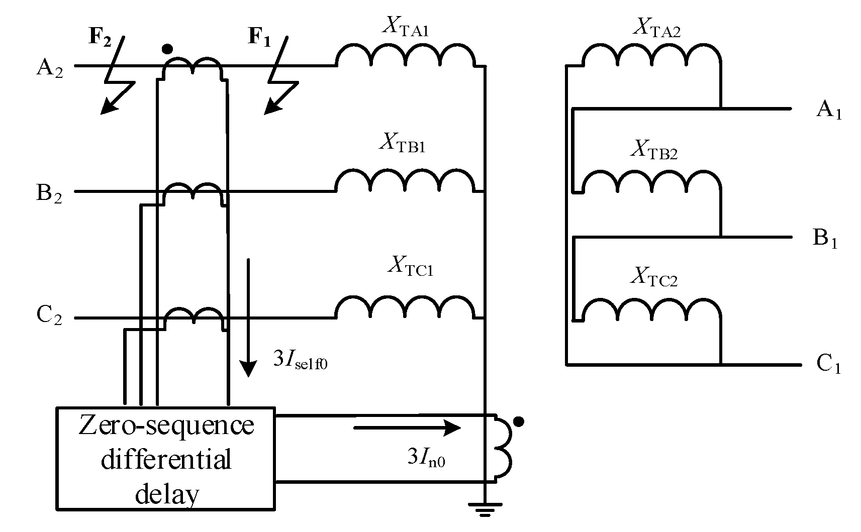
2. Principle of Zero-Sequence Differential Current Protection for Converter Transformer

The composition of the zero-sequence differential current protection of the converter transformer is shown in Figure 1. Zero-sequence differential current protection detects the internal grounding fault of the transformer through the difference between the zero-sequence currents at the terminal and the neutral point of the transformer. The phasor sum of terminal currents is three times the zero-sequence current, which is called terminal zero-sequence current 3 I ˙ self 0 . The current at the neutral point is also three times the zero-sequence current, which is called neutral point zero-sequence current 3 I ˙ n 0 . Positive directions of currents on both sides are shown in Figure 1. Under normal working conditions, due to the three-phase symmetry of the system, three times zero-sequence current flow through the neutral point 3 I ˙ n 0 = 0 . The sum of three-phase current flowing into the protection equipment is 3 I ˙ self 0   =   I ˙ A   +   I ˙ B   +   I ˙ C   =   0 , then 3 I ˙ self 0   =   3 I ˙ n 0   =   0 . When there is an internal fault in the system (Fault F1 in Figure 1), zero-sequence differential current is large enough to make the protection take action reliably. When external fault occurs in the system (Fault F2 in Figure 1), although 3 I ˙ self 0 and 3 I ˙ n 0 are no longer equal to zero, | 3 I ˙ self 0 |   =   | 3 I ˙ n 0 | is still true and the zero-sequence differential current protection will not operate. The operation criterion for zero-sequence differential current protection is:
I op   >   I op . 0 .   ,
In Equation (1), I op = | 3 I ˙ self 0     3 I ˙ n 0 | , where I op . 0 is the operating current of the zero-sequence differential current protection for the transformer. Generally, it is set as 0.3 times the rated current of the grounding winding of the converter, that is   I op . 0 = 0.3   p . u .

3. Impact of Recovery Inrush Current on the Zero-sequence Differential Current Protection

3.1. The Mechanism of Recovery Inrush Current of Fault on the Converter Transformer

For a general single-phase transformer, a T-type equivalent circuit can be used to simulate its transient mathematical model [11]. The T-type equivalent circuit of the transformer is shown in Figure 2.
In Figure 2, R1 and L1 represent the resistance and leakage inductance of the primary side, R2 and L2 represent the resistance and leakage inductance of the secondary side, Rm and Lm represent the excitation resistance and excitation inductance of the excitation branch, RL and LL represent the load resistance and load inductance, u represents the terminal voltage of the transformer, um is the excitation voltage; i1, i2 and im are the primary side current, secondary side current and excitation current respectively.
According to the transformer mathematical model, the relationship between the excitation potential um and terminal voltage u is:
u = R 1 i 1 + ( R 2 + R L ) i 2 + L 1 d i 1 d t + ( L 2 + L L ) d i 2 d t ,
u m = u     R 1 i 1     L 1 d i 1 d t ,
Let the source potential be u ( t ) = 2 U cos ( ω t + θ ) . Under normal operation, the resistance and inductance of the primary side of the transformer are so small compared with the secondary side that it can be ignored. At this time, the potential um of the excitation branch and the source can be considered as equal. Then the core flux of the transformer is:
ψ ( t ) = ψ m sin ( ω t + θ ) ,
where ψ m = 2 U ω . Let the transformer external fault occurs at t = 0, secondary resistance and inductance suddenly change to R2k and L2k. Excitation current becomes small and can be ignored as well. Let m = | R 2 k + j X 2 k | | R k + jX k | represent the severity of the external fault, R k = R 1 + R 2 k ,   X k   = X 1 + X 2 k = ω ( L 1 + L 2 k ) . Neglecting the influence of the primary side impedance, the potential of the excitation branch can be expressed as:
m u ( t )     m u = 2 m U cos ( ω t + θ ) ,
When the fault occurs, the core flux of the transformer will not change instantaneously. According to the Equation (4) and ψ ( 0 _ ) = ψ ( 0 + ) , the core flux of the transformer can be written as:
ψ ( t ) = m ψ m sin ( ω t + θ ) + ( 1     m ) ψ m sin θ ,
If we suppose the fault is removed at t = τ , secondary resistance and inductance immediately changes to R 2 and L 2 . When the fault cutting voltage is restored, primary impedance is small with respect to the secondary side, which means it can also be ignored. In this circumstance, the excitation branch potential um can be considered as approximately equal to the source potential u again. Regarding Equation (4) and ψ ( 0 _ ) = ψ ( 0 + ) , the magnetic flux of the transformer core is:
ψ ( t )     ψ m sin ( ω t + θ ) + ψ 1 , p , t   >   τ ,
The equation ψ 1 , p = ( 1     m ) ψ m ( sin θ sin ( τ ω + θ ) ) is called transformer bias, which causes the recovery inrush. In addition, the cutting angle and recovery angle also have a great impact on the amplitude of the magnetic bias, thus affects the severity of the recovery inrush current.
Figure 3 shows the flux change of the converter’s Y-type winding under external fault removal; the fault occurs at 1.0 s. The blue, red, and yellow lines in the figure represent the three-phase flux curves of phase A, B and C, respectively. It can be seen that the three-phase flux is affected by different cutting angles, they all have saturation phenomenon with different degrees. As a result, there will be an inrush in the process. Figure 4 shows the excitation current of the transformer, the blue, red and yellow lines represent the three-phase excitation current curves of phase A, B and C, respectively. It is apparent that in the voltage recovery process after fault removal, inrush occurs in all three phases and the inrush characteristics of each phase are different.

3.2. Effect of CT Saturation Caused by Recovery Inrush in Zero-Sequence Differential Current Protection

Because most of the converter transformers are composed of three independent single-phase transformers, the three-phase magnetic circuit will not affect each other in the process of fault and fault removal. When it comes to a three-phase group transformer, the phase angles between three phase voltages vary by 120°. Even if the fault occurs at the same time, the fault angles and cutting angles of each phase are different. According to the analysis of magnetic linkage in Section 3.1, saturation degree of the three-phase iron cores are not consistent, so that corresponding inrush current characteristics of each phase are different. The amplitude of zero-sequence current obviously increased after the superposition of three phase currents, accompanied by the appearance of a DC component and high-order harmonic.
Figure 5 shows the change of the zero-sequence current at the neutral point when external fault occurs and after it has been removed. The fault occurs during 1.00–1.05 s. There is also a small zero-sequence current in normal operation mode. In this case, zero-sequence current at the neutral point is symmetric with respect to time axis, having no effect on the transfer characteristics of CT. However, when the fault is removed, the amplitude of zero-sequence current rises up significantly. In the meantime, an asymmetric biasing phenomenon of positive and negative halves is generated, which may contribute to CT saturation and interfere with its normal transmission.
In order to analyze the mechanism of the distortion in zero-sequence current measurement at the neutral point, it is necessary to study the transfer characteristic of CT. In this paper, the J-A transformer model in PSCAD/EMTDC is adopted for analysis. In the J-A transformer model, parameters are mainly used to simulate different excitation curve trajectories, the expression for excitation current im relating to the saturation of the transformer is [12]:
d i m d t = l [ R ( i 2 i m ) + L σ d i 2 d t ] μ 0 N 2 A ( 1 + d M d H ) + l L σ ,
In Equation (8), l is the equivalent flux length of the transformer core; im is the excitation current of the transformer; i2 is the secondary current of the transformer; R is the load on the secondary (including the line loss on the winding), and Lσ is the leakage inductance of the winding; μ 0   is the magnetic permeability under vacuum; A is the equivalent cross-sectional area of the CT core; N is the number of turns of CT secondary winding; M is magnetization and H is the magnetic field intensity.
Due to the fact that three-phase currents of the converter are symmetric under normal operation, zero-sequence current is very small, and the anti-saturation ability of the CT at the neutral point is generally inferior to CT at the terminal. When there is an aperiodic component in the zero-sequence current, the remanence accumulation of the core may cause CT flux bias, which may further lead to CT saturation [13]. For zero-sequence differential current protection, it has high sensitivity but is not equipped with second harmonic braking. The transmission error caused by CT saturation at the neutral point may bring the risk of mis-operation.
Figure 6 shows the magnetic induction intensity of CT core at the neutral point before and after the fault. It is shown that after fault removal, the remanence accumulation of the iron core leads to the bias of CT flux, which seriously affects the normal transmission of CT and thus influences the operational reliability of zero-sequence differential current protection.

4. A New Principle of Zero-Sequence Differential Current Protection Based on Waveform Correlation Analysis

4.1. The Basic Principle of Waveform Correlation

Correlation analysis is mainly used to study the degree of similarity or dependence between two signals, so as to achieve the detection, identification and extraction of signals [14]. Assuming that the two zero-sequence current sequences in a certain period of time are x(n) and y(n), rab is defined as the correlation coefficient of x(n) and y(n):
r ab = n = 0 k c o v ( x , y ) n = 0 k V a r ( x ) V a r ( y ) ,
In Equation (9), cov(x,y) is the covariance of x(n) and y(n), Var(x) and Var(y) are the variances of x(n) and y(n). According to Schwartz’s inequality [14], the correlation coefficient of two signals | r ab |     1 . r ab   can reflect the correlation degree of amplitudes and phases angle between two current signals: the larger the r ab is, the more similar the two waveforms are. When the amplitudes of two current signals are proportional with the same phase, the correlation coefficient r ab = 1 , which is a strong positive correlation. When the amplitudes are proportional while their phases are opposite, the correlation coefficient r ab = 1 , which means a strong negative correlation. When their amplitudes are not proportional, 1   <   r ab   <   1 , representing a weak relation.
Figure 7 and Figure 8 show the waveforms of zero-sequent currents x(n) and y(n) under external (excluding CT saturation) and internal fault (excluding CT saturation). x(n) is zero-sequence current at the terminal of the transformer and y(n) is zero-sequence current at the neutral point of the transformer. Learning from these two figures, under normal circumstances, x(n) and y(n) are periodic functions with a period of 2π. When there is an external fault, the amplitudes of x(n) and y(n) waveforms are proportional and have the same phase, so that the correlation coefficient r ab is 1. When internal fault occurs, the amplitudes of x(n) and y(n) waveforms are proportional but the phases are opposite, the correlation coefficient r ab is −1. Therefore, the magnitude of correlation degree can clearly distinguish internal and external fault of the zero-sequence differential current protection.

4.2. A New Criterion for Zero-Sequence Differential Current Protection Based on Waveform Correlation Analysis

According to the analysis in Section 4.1, correlation analysis plays a role of amplifying the difference between signals, specifically the difference between the waveforms of two signals. To be exact, the larger the correlation coefficient is, the stronger the correlation is, vice versa. Based on the UHVDC transmission model, the sampling values 3 I ˙ self 0   and 3 I ˙ n 0 on both sides of the converter zero-sequence differential current protection are used to construct the following two current discrete signals [15]:
{ x ( n ) = 3 i self 0 ( n T ) y ( n ) = 3 i n 0 ( n T ) ,
In Equation (10), x(n) and y(n) are virtual current signals; 3 I ˙ self 0   is the sampling value of zero-sequence current at the terminal; 3 I ˙ n 0   is the sampling value of zero-sequence current at neutral point; T is the sampling interval.
After obtaining the discrete signals of currents on both sides, the correlation coefficient r ab is calculated according to Equation (9). When external fault occurs, the waveform amplitudes of zero-sequence currents on both sides of the protection are exactly the same and the difference of phase angles is nearly 0. It is a strong positive correlation and the correlation coefficient is 1. When the internal fault occurs, the waveforms of zero-sequence currents on both sides have little similarity and the difference of phase angles is close to 180°, which is a strong negative correlation and the correlation coefficient is close to −1. In order to distinguish internal and external faults, action threshold is set r ab .   set = R set . The improved criterion for zero-sequence differential current protection is shown in Equation (11):
{ I op   >   I op . 0 r ab ( i self 0 ,   i n 0 )   <   r ab .   set = R set ,
In the equation, r ab .   set is the action threshold of correlation coefficient and its action value R set is given with respect to the verification of actual parameters of ± 800   kV   UHVDC transmission model. r ab ( i self 0 ,   i n 0 )   is the correlation coefficient of zero-sequence currents on the two sides. Moreover, I op = | 3 I ˙ self 0     3 I ˙ n 0 | , I op . 0   is the operating current of the converter zero-sequence differential current protection, whose value is 0.3 times the rated current of the converter grounding winding [16,17], expressed as   I op . 0 = 0.3   p . u .

5. The Simulation Analysis

Converter transformer T1 on the rectification side in the ± 800   kV UHVDC transmission model was taken as the study object, as shown in Figure 9. Zero-sequence differential current protection measures i self 0 and   i n 0 on the Y0 winding side of converter. Relevant parameters of the simulation model are listed in Table 1 [18,19,20].
Validity of the new criterion in different typical fault scenarios is verified by analyzing the ± 800   kV UHVDC transmission model. For convenience of analysis, the neutral point CT uses a J-A model with a good saturation characteristic in PSCAD [21,22,23,24,25]. The total simulation duration is set to be 2.0 s and the current sampling rate is set to be 4 kHz. The window length of the identification criterion is selected as 20 ms. The calculation sequence of the correlation coefficient r ab is obtained through the passage of the time window.

5.1. External Fault of Converter Transformer (Excluding CT Saturation)

The established PSCAD/EMTDC model is used to simulate the situation of external fault of the converter transformer (excluding CT saturation). When the phase A external fault occurs at t = 1 s, the waveforms of   i self 0 and   i n 0 are detected by zero-sequence differential current protection as shown in Figure 10, noting that the blue line is   i self 0 and the red dotted line is   i n 0 . In Figure 11, the blue line is the calculation sequence of r ab and the dotted line is the calculation value of r ab under normal conditions. Since zero-sequence current is very small under normal conditions, zero-sequence differential current protection will not operate. The “1” here is false and does not refer to external fault.
It can be seen from Figure 10 and Figure 11 that when external fault occurs (excluding CT saturation), waveforms of two zero-sequence currents almost coincide completely with the same phase, which is strong positive correlation and is judged as an external fault. During the duration of the fault, the two current waveforms are consistent in general, as good as no difference in amplitude and phase. The amplitude of the zero-sequence differential current is close to 0, which is far lower than the action value of protection, so the protection can block reliably.
During the duration of the external fault, large zero-sequence current may give rise to the saturation of neutral point CT. The deterioration of CT transmission characteristic will result in a large zero-sequence differential current, leading to the mis-operation of traditional zero-sequence differential current protection. Such kind of working condition is verified below.

5.2. External Fault of Converter Transformer (Taking CT Saturation into Account)

When the phase A external fault occurs at t = 1 s with CT saturation, the zero-sequence differential current protection detects the waveforms of iself0 and in0 as shown in Figure 12. The meaning of each waveform and variable is the same as in Section 5.1.
In regard to Figure 12a, the neutral point CT is saturated and in0 transmission is deformed after saturation. Here, zero-sequence current waveforms of two sides are weakly positively correlated. Figure 12b shows the waveform of zero-sequence differential current with CT saturation. Its amplitude is close to 0.49 p.u., which is larger than the action current 0.3 p.u., so traditional zero-sequence differential current protection will mis-operate. Using the criterion proposed in this paper, the calculation result of correlation coefficient sequence   r ab for iself0 and in0 is shown in Figure 13. The minimum value of r ab is 0.96.
In addition to the protection mis-operation caused by CT saturation during the external fault, according to the analysis in Section 3.2, neutral point CT accumulates a certain remanence during the external fault. After it is removed, the CT is affected by the recovery inrush current. The cumulative effect of remanence will cause the saturation of CT. Furthermore, the false differential current is generated after the removal of external fault, bringing about the mis-operation of the traditional zero-sequence differential current protection. Therefore, the reliability of the new criterion for zero-sequence differential current protection under such condition is verified below.

5.3. Recovery Inrush Current (Taking CT Saturation into Account)

Phase-A external grounding fault occurs at t = 1 s and is removed after 0.05 s. The waveforms of iself0 and in0 detected by zero-sequence differential current protection are shown in Figure 14a.
Considering the scenario when the recovery inrush current is more serious, three-phase flux of the converter transformer is seriously asymmetric. CT at the neutral point is affected by the recovery inrush current. As its magnetic bias accumulates continuously, CT gets saturated as a result. Zero-sequence current is distorted after transmission and there is a little deviation in phase. False differential current is also generated. Figure 14b shows the waveform of zero-sequence differential current on condition that CT is saturated under recovery inrush current. Two waveforms are weakly positive correlated. It can be learned that after the fault is removed, since the CT at the neutral point is saturated, there will be false differential current in differential current protection with maximum amplitude being 0.51 p.u., which is higher than the protection action value. If no locking criterion is added, the zero-sequence differential protection will mis-operate. According to the criterion proposed in this paper, the calculation result of correlation coefficient sequence of iself0 and in0 is shown in Figure 15, and the minimum value of r ab is 0.57.

5.4. Internal Fault of Converter Transformer (Excluding CT Saturation)

The single-phase grounding fault occurs at t = 1 s. The waveforms of iself0 and in0 detected by zero-sequence differential protection are shown in Figure 16a.
It can be seen that after the waveforms of the internal fault tend to be stable without CT saturation, the phases of iself0 and in0 are opposite. The differential current is shown in Figure 16b. The difference between amplitudes increases significantly, which is much higher than the protection action value. Calculating the correlation coefficient of zero-sequence currents on both sides, the calculation sequence of r ab is shown in Figure 17. The amplitudes of two current waveforms are proportional and the phases are opposite, which is strongly opposite correlation. The minimum value of r ab is −1.
The zero-sequence current changes at the moment when the fault occurs. Currents on both sides are almost the same before the fault occurs, r ab   = 1. However, the phase of zero-sequence current on the fault side is reversed, causing r ab changes to −1 within one cycle, which can accurately identify internal fault and external fault.

5.5. Internal Fault of Converter Transformer (Taking CT Saturation into Account)

The phase-A internal grounding fault occurs at t = 1 s with CT saturation. The waveforms of iself0 and in0 detected by zero-sequence differential current protection are shown in Figure 18a, and the waveform of differential current is shown in Figure 18b.
It can be seen that when CT is already saturated, amplitude difference still increases apparently, to much higher than action value. Figure 19 shows the calculation sequence of r ab under internal fault with CT saturation. The amplitudes of two waveforms are proportional and the phases are opposite, r ab changes to −1 within one cycle after the fault occurs. The minimum value of r ab is −1, which can identify internal faults and external faults precisely.
Table 2 shows the simulation results under different fault conditions, based on the analysis in Section 5.1 to 5.5, the correlation coefficient of recovery inrush current with CT saturation is the smallest, at exactly 0.57. Namely, the critical correlation coefficient r abd = 0.57. Considering the practical engineering need and the inconsistency of CT transfer characteristics in each case, the critical correlation coefficient can be appropriately reduced to improve the reliability of the criterion, so that the operation threshold Rset is set as 0.4. The identification criterion for zero-sequence differential current protection based on waveform correlation analysis is expressed by Equation (12), where the variables have the same meanings as Equation (11).
{ I op   >   I op . 0 r ab ( i self 0 , i n 0 )   <   r ab .   set = 0.4 ,
Therefore, after the protection is started, if Equation (12) is satisfied, it will be judged as an internal fault. On the contrary, the fault is judged as an external fault and the protection is locked reliably. Verification results are presented in the fourth column of Table 2. The results show that present zero-sequence differential current protection has a certain risk of mis-operation, while the zero-sequence differential current protection strategy based on waveform correlation analysis proposed in this paper has a strong CT anti-saturation capability. It can also operate correctly when CT saturation is caused by recovery inrush current.

6. Conclusions

Zero-sequence differential current protection is an important protection method for the converter transformer to deal with winding grounding faults, but present zero-sequence differential current protection has the risk of mis-operation in the case of recovery inrush current with CT saturation, when external fault persists and is removed. In this paper, by analyzing the amplitude and phase characteristics of zero-sequence currents on both sides of zero-sequence differential current protection, combined with correlation analysis that can magnify the difference between signals, the new criterion for zero-sequence differential current protection of the converter transformer based on correlation analysis is proposed. The simulation results are verified based on the HVDC transmission model. The results show that the traditional zero-sequence differential current protection may mis-operate under external fault persistence and removal accompanied by CT saturation. The proposed new criterion for zero-sequence differential current protection based on waveform correlation can be locked reliably. It can operate sensitively in all kinds of internal fault conditions. It has strong CT anti-saturation ability, as well as the reliable ability of identification even when external fault removal causes recovery inrush current with CT saturation.

Author Contributions

Conceptualization, T.Z. and X.Y.; Data curation, X.G.; Formal analysis, X.Y.; Methodology, X.G.; Project administration, T.Z.; Supervision, X.W.; Validation, X.W.; Writing—original draft, T.Z. and X.Y.; Writing—review & editing, X.Y. and C.Z. All authors have read and agreed to the published version of the manuscript.

Funding

This research was funded by the Science and Technology Project of State Grid Corporation of China (Research on Multi-type Power Equipment Fault Identification and Protection Technology) (5100-201955017A-0-0-00).

Conflicts of Interest

The authors declare no conflict of interest.

References

  1. Wang, W. Necessity of zero-sequence differential protection for large-sized transformer. Electr. Power Autom. Equip. 2003, 23, 1–5. [Google Scholar]
  2. Zhang, X.; Shan, Q.; Zhang, X. Several problems on zero-sequence differential protection for transformer. Relay 2005, 33, 13–17. [Google Scholar]
  3. Zhu, S. Discussion on transformer zero-sequence current differential protection. Electr. Power Autom. Equip. 2003, 23, 5–8. [Google Scholar]
  4. Shi, H. Analysis of a 500 kV transformer zero-sequence differential protection mis-operation accident. In Proceedings of the 13th national symposium on protection and control, Nanjing, China, 1 December 2011; pp. 62–64. [Google Scholar]
  5. Zhan, Q.; Wang, S.; Zhang, S. Analysis of a 500 kV transformer zero-sequence differential protection fault and its prevention. Relay 2007, 35, 71–73. [Google Scholar]
  6. Shan, Y. Analysis of a 220 kV autotransformer zero-sequence differential protection fault and its prevention. In Proceedings of the 2011 Yunnan Electric Power Technology Forum, Yunnan, China, 15 November 2011. [Google Scholar]
  7. Luo, Y.; Chen, Z. On the algorithm of resisting current of transformer’s zero-sequence differential protection. South. Power Syst. Technol. 2011, 5, 77–80. [Google Scholar]
  8. Wu, D.; Yin, X.; Zhang, Z.; Bao, K.P. Zero-sequence current automatic compensation of transformer differential protection based on negative-sequence current. Electr. Power Autom. Equip. 2007, 27, 28–31. [Google Scholar]
  9. Ding, S.; Lin, X.; Zhang, Z. Mal-operation risk analysis and countermeasure on ze-ro-sequence differential protection of converter substation during existence of recovery inrush due to fault removal. Proc. CSEE 2017, 33, 13–17. [Google Scholar]
  10. Lu, J. Operation Performance Analyses and Novel Principles Studies on Differential-Type Protections of Power Transformer Under AC-DC Deeply Coupling Interactions; Huazhong University of Science and Technology: Wuhan, China, 2016. [Google Scholar]
  11. Zheng, T.; Wang, Z.; Wong, H.; Lin, X. Key Technology and New Principle of Differential Protection for EHV / UHV Transformers; Beijing Science Press: Beijing, China, 2017. [Google Scholar]
  12. Lei, Y.; Duan, J.; Zhang, X.; Li, Y.G.; Zhang, Y.Y.; Zhang, W.C.; Jin, Z.T. Identification of current transformer J-A model parameters with large current dynamic simulation experiments. Proc. CSEE 2016, 36, 240–245. [Google Scholar]
  13. Wong, H.; Liu, L.; Lin, X.; Jin, N.; Li, Z.; Huang, J. Mechanism and countermeasures of mal-operation of converter transformer zero-sequence overcurrent protection casused by inrush currents. Autom. Electr. Power Syst. 2019, 43, 171–182. [Google Scholar]
  14. Li, X.; Luan, Q.; Wang, Y.; Tan, L.; Hao, H. Bus-bar protection scheme based on correlation of coefficients of sampled current values. Autom. Electr. Power Syst. 2014, 38, 107–111. [Google Scholar]
  15. Chen, D.; Huang, J.; Zhang, L. Identification of transformer excitation inrush based on correlation analysis between two Fourier algorithms. Electr. Power Autom. Equip. 2010, 30, 71–74. [Google Scholar]
  16. Zou, G.; Huang, Q.; Song, S.; Tong, B.; Gao, H. Novel transient-energy-based directional pilot protection method for HVDC line. PCMP 2017, 2, 15. [Google Scholar] [CrossRef]
  17. Zheng, T.; Guo, X.; Hu, X.; Yu, Y.; Zheng, X.; Wang, X. Mechanism of fault inrush current of inverter-side converter transformer and its influence on differential protection. Electr. Power Autom. Equip. 2019, 39, 39–45. [Google Scholar]
  18. Wu, Z.; Zeng, G.; Li, Y.; Wang, F.; Tu, Q.; Yang, Y.; Zhao, Q. A novel criterion for fast protection of transformer based on Hausdorff distance and double threshold. Power Syst. Prot. Control. 2019, 47, 128–135. [Google Scholar]
  19. Zhang, K.; Qi, X.; Hu, W.; Zhang, S.; Chen, K.; Yin, X. Impact of the CT saturation of the delta winding on the HVDC protection and its countermeasure. Power Syst. Prot. Control. 2016, 44, 99–105. [Google Scholar]
  20. Guzman, A.; Zocholl, S.; Benmouyal, G.; Altuve, H.J. A current-based solution for transformer differential protection, part II: Description and evaluation. IEEE Trans. Power Deliv. 2002, 17, 886–893. [Google Scholar] [CrossRef]
  21. Angel, R.; Juan, C.B. Influence of tertiary stabilizing windings on zero-sequence performance of three-Phase three-Legged YNynd transformers. part II: Tank overheating hazard and short-circuit duty. Electr. Power Syst. Res. 2017, 145, 149–156. [Google Scholar]
  22. Suonan, J.-L.; Zhang, J.-M.; Xu, L.-Q.; Tan, S.-F. Study of zero-sequence differential protection for transformer with Yn/Δ connection. Power Syst. Prot. Control. 2010, 38, 54–61. [Google Scholar]
  23. Wang, B.; Li, B.; Song, X. Verification method for transformer CT wiring based on instantaneous power theory. Power Syst. Prot. Control. 2019, 47, 173–179. [Google Scholar]
  24. Cao, W.; Qi, X.; Zhang, K.; Yin, X.; Zhang, Z.; Guo, Q. The impact of the CT saturation on the HVDC protection and its countermeasure. IEEJ Trans. Electr. Electron. Eng. 2017, 12, 834–840. [Google Scholar] [CrossRef]
  25. Li, S.; Ding, R. An identification method for low-frequency oscillation based on signal correlation. Power Syst. Prot. Control. 2018, 46, 46–54. [Google Scholar]
Figure 1. Schematic wiring diagram of zero-sequence differential current protection for the converter transformer.
Energies 13 01814 g001
Figure 2. Transformer T-type equivalent circuit.
Energies 13 01814 g002
Figure 3. Flux of the converter transformer under external fault removal.
Energies 13 01814 g003
Figure 4. Field current of the converter transformer under external fault removal.
Energies 13 01814 g004
Figure 5. Zero-sequence current waveform at the neutral point under external fault.
Energies 13 01814 g005
Figure 6. Magnetic induction intensity of iron core at the neutral point CT after fault removal.
Energies 13 01814 g006
Figure 7. Waveforms of zero-sequent currents under external fault (excluding CT saturation).
Energies 13 01814 g007
Figure 8. Waveforms of zero-sequent currents under internal fault (excluding CT saturation).
Energies 13 01814 g008
Figure 9. Schematic diagram of the UHV bipolar 12-pulse converter unit.
Energies 13 01814 g009
Figure 10.   i self 0 and   i n 0 waveforms under external fault (excluding CT saturation).
Energies 13 01814 g010
Figure 11. r ab calculation sequence under external fault (excluding CT saturation).
Energies 13 01814 g011
Figure 12. Waveforms under external fault (taking CT saturation into account): (a) iself0 and in0; (b) zero-sequence differential current.
Energies 13 01814 g012
Figure 13. r ab calculation sequence under external fault (taking CT saturation into account).
Energies 13 01814 g013
Figure 14. Waveforms under recovery inrush current (taking CT saturation into account): (a) iself0 and in0; (b) zero-sequence differential current.
Energies 13 01814 g014
Figure 15. rab calculation sequence under recovery inrush current (taking CT saturation into account).
Energies 13 01814 g015
Figure 16. Waveforms under internal fault (excluding CT saturation): (a) iself0 and in0; (b) zero sequence differential current.
Energies 13 01814 g016
Figure 17. r ab calculation sequence under internal fault (excluding CT saturation).
Energies 13 01814 g017
Figure 18. Waveforms under internal fault (taking CT saturation into account): (a) iself0 and in0; (b) zero-sequence differential current.
Energies 13 01814 g018
Figure 19. r ab calculation sequence under internal fault (taking CT saturation into account).
Energies 13 01814 g019
Table 1. Simulation model parameters.
ParametersValue
Rated Capacity (MW)760
Rated Ratio (kV)525/170
Connection MethodY0/Y
Positive Sequence Linkage (p.u.)0.18
Hollow Reactance (p.u.)0.2
Saturation Point (p.u.)1.25
Excitation Current (p.u.)1%
Table 2. Simulation verification results under different fault conditions.
Fault TypeTraditional Zero-Sequence Differential Protection CriterionNew Criterion of Zero-Sequence Differential Protection Based on Waveform Correlation
Amplitude of Differential Current (p.u.)Action SituationMinimum Value of Correlation Coefficient
rab.min (p.u.)
Action Situation
Internal FaultMetallic grounding without CT saturation1.6−1
Grounding through a 10Ω transition resistor without CT saturation1.1−1
Grounding through a 100Ω transition resistor without CT saturation0.62−1
Metallic grounding with CT saturation1.15−1
External FaultMetallic grounding without CT saturation0×1×
Metallic grounding with CT saturation0.49*0.96×
Recovery Inrush CurrentExternal fault removal without CT saturation0×0.99×
External fault removal with CT saturation0.51*0.57×
Note: √ represents protection action, × represents protection does not action, * represents the protection mis-operate.

