1. Introduction
The energy consumption of space heating and cooling has attracted attention, and thermal transmittance (
U-value) must be limited to maximum acceptable values for commercial and residential buildings according to construction regulations and related energy efficiency standards [
1,
2,
3]. Therefore, increasing the normal thermal resistance (
R-value in steady state) of a building envelope is the main measure used to protect the indoor environment from extreme external conditions and reduce the energy consumption on space heating and cooling. However, these factors are not sufficient to characterize the dynamic thermal behavior. In a transient situation, the thermal mass of a structure can store or release heat depending on the surrounding temperature differences. Balaras [
4] reviewed tools for calculating cooling load, accounting for thermal mass, and indicated the effectiveness of thermal mass on an indoor thermal environment and energy conservation, particularly in the places with deep diurnal temperature differences. Regulating the amount of thermal mass can increase the time lag and decrease the temperature fluctuation in a conditioned space. Optimizing the thermal mass has been regarded as an important measure for passive heating/cooling strategies and for designing low-energy buildings [
5,
6,
7]. Besides, the phase change materials (PCMs) embedded in a building enclosure are regarded as a useful passive method to increase in heat storage capacity and thermal inertia further [
8]. The structures are expected to narrow indoor temperature fluctuations and reduce energy demands [
9], and the integration of PCM technologies has been on trial in some net-zero energy buildings recently [
10,
11].
Many studies have focused on the investigation of thermal behavior for an individual building envelope with the objective to optimize arrangement of insulation and massive layers. Al-Sanea [
12] developed a concept of dynamic thermal resistance, accounting for the influences of wall orientation, long wave radiation exchange, thermal energy storage, and nominal thermal resistance. With this concept, Al-Sanea et al. [
13,
14] investigated the effects of insulation locations and various amounts of thermal mass on thermal performances of building external walls based on the climate of Riyadh. They recommended that building walls should contain a minimum critical amount of thermal mass, and that the insulation be placed on the outside in a case where the air conditioning system runs continuously; otherwise the insulation layer should be placed on the inside. Tsilingiris [
15,
16,
17] investigated the effects of various insulation configurations and heating systems on the energy loss through a building envelope. The results showed that the position of a massive layer strongly influences the transient heat transfer through the structure, but that it has no effect on the heat flux in the time-average quasi steady-state; and they also confirmed that the thermal insulation performs better when located at the inside in an intermittently conditioned room. Deng et al. [
18] suggested that the high thermal mass in an external wall should be directly faced toward the indoor air to avoid overheating in the part-time, part-space cooling conditions. An experimental study by Kumar et al. [
19] showed that a high inside mass can help to reduce excess heat discomfort for a significant time; i.e., 40% and 98% of the summer and winter respectively in a naturally ventilated office building in India. Reilly and Kinnane [
20] developed new metrics (transient energy ratio and effective U-value) to quantify the effects of thermal mass on the energy use for heating and cooling. They found that a high thermal mass possibly causes reductions in energy use in a hot climate with big diurnal temperature differences, but it could lead to more energy use in cold climates. In addition, with the building energy simulation tools being well-developed, the transient thermal behavior can be investigated, and the effect of thermal mass on energy performance can be evaluated in a building approximating real-life, wherein the occupancy gain, solar gain, and HVAC operation strategies can be involved. Rodriguez et al. [
21] stated that human behavior is one of the most important factors when understanding building physics. Eben Saleh [
22,
23] used a computer program named National Bureau of Standards Load Determination to analyze the energy use of an entire building and showed that placing the insulation on the outside of the building envelope can improve performance. Kossecka and Kosny [
24,
25] utilized simulation software DOE to investigate the thermal performances of six different configurations used in residential buildings in different USA climates. They recommended that a wall with an internal insulation layer can improve performance in a continuously used residential building, but indicated that a wall with inside insulation can enhance performance for intermittent heating and cooling. Verbeke and Audenaert [
26] reviewed the impacts of thermal inertia in buildings across climate and building use, and suggested that assessing the impact of thermal inertia should be based on studies on the scale of whole buildings. According to their conclusion, the impacts of thermal inertia on energy use are relatively small and variable, with both positive and negative performances existing, but the thermal inertia can be used to shift the peak-load of an HVAC system in a proper control strategy.
In the light of the previous studies, additional problems have still not been focused on or clearly addressed:
Previous studies were based on investigations of indoor air temperature, and few considered envelope surface temperatures;
Many studies were based on situations wherein conventional heating and cooling systems were applied, without noting the differences in the heat transfer process for a radiant system.
At present, the radiant system has been widely used in recent years and is regarded to have many advantages in indoor environmental control and energy efficiency [
27]. As an alternative cooling method, the radiant system is suggested to make use of the construction thermal mass to shift the peak HVAC system cooling load and power use [
26,
28]. However, as stated by Niu et al. [
29], the radiant effect of a chilled ceiling can decrease the heat storage capacity of a building envelope. Feng et al. [
30,
31] also indicated the cooling load differences between radiant and air systems through simulation and measurement verification. Several methods of operating the radiant system in practice are available [
32,
33], and appropriate scheduling techniques can provide some opportunities to reduce the energy consumption with smaller initial investments [
34]. The present authors [
35] have conducted research on the operating characteristics of two radiant systems using various strategies in a typical office building through simulative and on-site measurements. The thermal mass of a slab can be utilized for cooling storage to shift the peak cooling load, particularly for a thermally active building system (TABS) in which a hydronic system is deeply embedded in the slab. In addition, an experimental study by Tahersima et al. [
36] showed that the mass in the radiant floor can also be used for heating conservation during off-peak hours, and the operational costs result in significant savings.
On the basis of those considerations, the present study analyzed the effects of thermal mass in external walls on transmission loads in spaces with radiant cooling systems, and we present the differences from an identical room equipped with only an equivalent convective air system (CAS). In addition, operative temperature was used to evaluate the thermal comfort level in a room with radiant surfaces [
37,
38,
39,
40]. That parameter combines room air temperature and radiant temperature, weighted by convection and radiation heat transfer coefficients respectively.
2. Methodology
In a zone with a CAS alone, convection heat gain directly becomes the cooling load of the CAS, whereas instantaneous radiation gain is absorbed and stored in the thermal mass, and then converted to be the cooling load by convection with a time lag (
Figure 1a). In a zone with a radiant system (
Figure 2), which usually acts as a cooling ceiling or a floor, a CAS as an auxiliary system is necessary to maintain the indoor hygiene level, and is responsible for the zone latent load. Thus, besides the convection gain which is immediately handled by the auxiliary CAS, a part of the radiation heat gain is directly absorbed by the cooling surface (active surface). The remaining radiation heat gain is absorbed by the structure or furniture and then extracted by these two systems simultaneously (
Figure 1b).
Dynamic simulation is generally a reliable method used to compute heat transfer in a given zone [
42]. Feng et al. [
30] stated that the heat balance method should be employed to calculate the cooling loads of radiant systems; and used the Energy-Plus simulation software to assess the cooling load. Energy-Plus was developed by U.S. Department of Energy and Lawrence Berkeley National Laboratory. The present algorithm models have been validated according to the standard method of test for the evaluation of building energy analysis computer programs (ANSI/ASHRAE 140) [
43]. Thus, the Energy-Plus simulation software was also selected for computing instantaneous heat transfer in a building with cooling surfaces in this study. The algorithm is based on the conduction transfer function.
In this study, the results of instantaneous heat extracted from a given zone (, heat extracted by a cooling surface , and the portion due to radiation ( are significant for analysis, but they cannot be directly obtained from the simulation, and the deduction process is as follows.
In a conditioned space, heat balances of an inside face and the indoor air can be expressed as follows:
Thus, total convection heat transfer from surfaces in an envelope can be expressed as follows:
and the cooling load of the air-conditioning system can be expressed as follows:
In a zone where a hydronic system is contained in a concrete floor or ceiling (
Figure 2), the heat can be conducted from both sides to the internal source. Thus, the heat extraction at cooling surfaces can be expressed in Equation (5) as follows.
Thus, the heat extraction from the thermal zone (
can be expressed as follows:
However, the size of a radiant system cannot be directly assessed by the Energy-Plus simulation software, because only CAS is assumed when sizing a calculation. For the consideration of differences in the heat transfer process between the zones with and without a radiant system, hydronic systems are assumed in an initial simulation, and the parameters (pipe dimension, water flow rate, water inlet temperature, etc.) refer to many practical items. Thus, repeat computations must be implemented until the room operative temperature can meet the design criteria.
Instantaneous zone radiation heat gain
is distributed to the surfaces according to their surface temperatures and shape factors; it is the sum of short wave and long wave radiation gains:
Radiation heat gain at the active surfaces
can be obtained using Equation (8):
When , a part or all of the radiation heat gain is absorbed by the active surfaces via direct and indirect radiation transfer; for , not only is the zone radiation heat gain absorbed, but also more conductive heat transfer on inactive surfaces is compensated by the active surfaces through radiation heat transfer. (Heat gain on the fenestration surface, excluding short-wave transmitted heat gain, is grouped under conduction heat gain for simplicity in this study.)
2.1. Influencing Parameters
The parameters that influence thermal mass performance generally include the thermal environment condition, construction, occupant scheduling, and the heating ventilation and air-conditioning (HVAC) system and its own operational strategy [
4].
2.1.1. Thermal Environment Conditions
The effect of thermal mass is clear in the places with moderate climate or deep diurnal temperature differences [
4,
10,
16]. This study selects two typical places in China as examples; namely, Beijing and Nanjing. According to the Chinese Building Climate Demarcation [
44], Beijing is in the cold area, where the maximum air dry-bulb temperature reaches 34.73 °C on a cooling design day (e.g., July 21, and referenced as BJ_7/21) and varies over a large range (i.e., 8.6 K); meanwhile, Nanjing is in the hot summer and cold winter area, where the peak value is 35.1 °C on the cooling design day, and the temperature difference between the maximum and minimum values is 6.5 K. On a typical day in the transient season (e.g., June 14), the peak outdoor air dry-bulb temperature in Beijing remains high (i.e., 32.71 °C), but the minimum temperature decreases to 19.17 °C. By contrast, on the typical day in Nanjing (referenced as NJ_6/14), the temperature decreases, ranging from 19.25 °C to 27.89 °C. In addition, indoor design temperature can be set as 26 °C (operative temperature) during the occupied period (07:00–19:00).
2.1.2. Building and Construction
The simulation is based on a typical office building with 20 floors. The plan of a standard floor is illustrated in
Figure 3a. The external window area accounts for 50% of the wall, and the exterior blinds work when the incident solar intensity exceeds 50 W/m
2. The external wall is mainly composed of extrusion polystyrene insulation (XPS) and concrete (
Figure 3b), and the thermal properties of the structures meet the national building efficiency standard [
3]. The internal heat gains and their scheduling are illustrated in
Figure 3c.
The insulation and concrete in the external wall are sandwiched by two thin cement mortar layers, and the concrete layer is placed inside (
Figure 3b). Thermal mass can be defined as the specific capacity multiplied by the mass of construction. For the 1D structure, the thermal mass per square meter of the external wall can be written as follows:
where
Cpi is the specific capacity, J/kg·K;
is the density, kg/m
3; and
is the layer thickness, m.
Given that specific capacity and material density are fixed, the layer thickness is the only function of the thermal mass of the construction. The normal thermal resistance of the external wall remains constant to distinguish the effects of thermal mass on the indoor environment, transmission load, and room sensible cooling load in a perimeter zone. Thus, the thermal mass increases as the thickness of the concrete layer increases, whereas the thickness of the insulation layer decreases.
Table 1 shows that the thermal mass in external walls without concrete layer (lightweight structure) only accounts for 10% of the total in a perimeter zone on one standard floor in the office building, and the percentage increases to 43% as the thickness of the concrete layer extends to 200 mm.
2.1.3. HVAC System and Operational Strategy
The output of a radiant system should vary with climatic change, and the hydronic system has variable water flow rate but constant supply temperature. For considering the effect of thermal mass surrounding a hydronic system (the concrete slab acts significantly as a regenerator in TABS [
35]), the embedded surface cooling system (ESCS) is only selected to determine the significant effect of thermal mass in the external walls on the heat transfer and transmission load in the zone with a radiant system.
The auxiliary CAS in the combined system (ESCS+CAS) is only responsible for fresh air cooling load and indoor latent load. It supplies conditioned air with a constant flow rate (1 ac/h) at a constant dry-bulb temperature (15 °C). Thus, the CAS is simulated with priority.
System operation strategy is a main factor which affects the thermal mass performance [
13]. The conventional operation scheduling technique (OPCT), wherein the cooling system is available 24 h/day and the room temperature set point is adjusted to achieve energy savings, has been widely applied [
45,
46,
47,
48]. Thus, the auxiliary CAS runs continuously during the occupied period, and the hydronic system in ESCS operates according to the setting of the room thermostat.
An equivalent CAS is also considered in the identical perimeter zones and operates according to the strategy OPCT.
2.2. Definition
The parameters decrement factor and thermal phase lag, are frequently used to describe the effects of thermal mass in studies, and the specific definitions are listed as follows.
2.2.1. Decrement factor (f)
The decrement factor is a dimensionless factor which describes the change in amplitude of a sinusoidal heat transfer through a building component (
Figure 4a), and it is generally expressed by the ratio of amplitude of temperature excitation to the value of response (Equation (10)) [
26].
2.2.2. Thermal Phase Lag ()
The thermal phase lag determines how long it takes for excitation heat to go through an opaque material, and it represents the time difference between the moments when the maximum excitation and response heat fluxes occur (
Figure 4b) [
26].
According to the above definition, the instantaneous heat fluxes occurring on both sides of an opaque wall can be used to calculate decrement factor and thermal phase lag directly. The decrement factor in the article is defined by the ratio of the maximum conduction heat gain on the inside face to the maximum excitation heat on the outside face of an external wall.
2.2.3. Relative Effect (R)
In order to distinguish the effect of thermal mass in the zone with a combined system from the performance in the zone with an equivalent CAS, a parameter named relative effect is used and is defined as
where
is the decrement factor of a wall which is heavy (light).
3. Results
The effect of thermal mass on the room cooling load is limited in the perimeter zones. The peak room sensible cooling load and the accumulated load (
) decrease by 1% to 2% as the thickness of the concrete layer in the external wall increases from 0 to 200 mm. The data shows only a slight change as the thermal mass increases further (
Figure 5). There are two main reasons. The first is that the conduction heat gain only accounts for a small portion of the total heat gain in the building at the peak time when the maximum building cooling load occurs; that is, only 3% or less in the perimeter zones (
Figure 6). The second reason can be illustrated by
Figure 7; only a very narrow gap in accumulated transmission load exists between the structures of light weight and of heavy weight when the same cooling system applied to maintain an identical indoor thermal environment. It also confirms some preceding research: the thermal mass has little impact on building energy consumption [
15,
16,
17,
27].
In addition, the peak cooling load of the zone with an ESCS is higher than the load of the zone with an equivalent CAS by 9% to 11%, and the accumulated load is also higher by 3%–4% based on same weather conditions. As
Figure 7 illustrates, accumulated conduction heat gain through an external wall with a heavy thermal mass in the zone with an ESCS is still more than the amount on the wall with a lightweight structure in the zone with an equivalent CAS when the degree-hours are selfsame. These results are basically consistent with the findings from the laboratory experiment conducted by Woolley et al. [
49]. The tests were carried out in a standard climatic chamber, and two separated tests were implemented side-by-side: one with a radiant cooling ceiling, and the other with an overhead mixing air distribution system. The results showed that the peak cooling load of the radiant system was 2%–10% larger than the load of air system in the case where internal heat gain varied periodically, and the accumulated load was 2%–7% higher. The experiment also confirmed the differences existing in heat transfer processes between the zones with and without a radiant system, but it did not explain the effect of thermal mass further.
The instantaneous transmission load has obvious varietious between the constructions with different thermal masses. As
Table 2 and
Table 3 state, the internal thermal mass helps to decrease the transmission through external structures in different orientations, especially on the typical days in the transient season. By comparing the performances in the zone with an equivalent CAS, the effect of thermal mass is more evident in the zone with an ESCS on the cooling design days, while it becomes less on the days in transient season.
In addition, the internal thermal mass prolongs the phase lag for some structures with various orientations, especially on the typical days in transient season (
Table 2 and
Table 3).
According to the impact factors mentioned above, the climatic situation, and the thermal mass position, the specific analysis is as follows by taking the performance in the north perimeter zone as an example.
3.1. Effect of Thermal Mass on System Performance in Different Climates
3.1.1. Performance on Cooling Design Days
On the cooling design days in the cities of Nanjing and Beijing, the minimum outdoor dry-bulb temperatures are higher than the room setting temperature; i.e., 26 °C. The inside face temperatures of external opaque walls are lower than the temperatures of the outside faces during the occupied period, for the structures with and without a concrete layer. In addition, for the external opaque surfaces which contain the same structure, the inside face temperatures appear lower in the zones with ESCSs compared to the temperatures in the zones with CASs (
Figure 8a). Since the heat transfer process in the zone with an ESCS is different from the process in the zone with a CAS (
Figure 1), most of instantaneous radiant heat gain can be absorbed by the cooling surface through direct or indirect radiant heat transfer (
Figure 9a). This also confirms the statement by Niu et al. [
29]: the cooling surface can decrease the heat storage capacity of the building envelope to the radiation heat transfer. Besides, a big portion of conduction occurring on the inside faces of the external walls is balanced by radiation instead of convection (averages of about 66% and 88%, respectively, for the zone with heavy weight and the zone with light weight). The instantaneous radiation heat fluxes on the inside faces are related to the cooling surfaces during the occupied period (
Figure 9a), such that heat fluxes are conducted from the outside faces to the inside in this time, and the instantaneous conduction heat gains on the inside faces have approximate values in the most of the occupied time when these cooling systems operate to maintain the indoor environment within the given criteria (
Figure 10a). However, the thermal mass in the external wall can help to maintain the inside face temperature stably, and the transmission loads through the external walls with heavy weights are lesser than the ones through the walls without concrete layers (
Figure 10a). Consequently, compared to the performance in the zone with an equivalent CAS, the maximum conduction heat transfer on the inside face is slightly lower in the zone with an ESCS, and the relative effect of thermal mass (R) appears more significant on the cooling design days.
In contrast to the performances during the occupied period, more transmission loads are observed on the external walls with heavy weight structures during the unoccupied period, compared to the loads on the walls of a light weight in the zones with same cooling systems. It is due to the fact that the inside face temperatures of the external surfaces with heavy weight structures still stay higher than the corresponding room operative temperatures in this time; meanwhile, the inside face temperatures of the surfaces with lightweight structures decrease and approach the corresponding operative temperatures after the midnight. For a same structure, a wider gap exists between the inside face temperature and the corresponding operative temperature in the zone with an ESCS in comparison with the performance in that zone with a CAS. More radiation heat transfers occur on the surfaces in the zones with ESCSs, and the consequent conduction heat gains are higher in most of the unoccupied period, and the accumulated values (
Figure 10a).
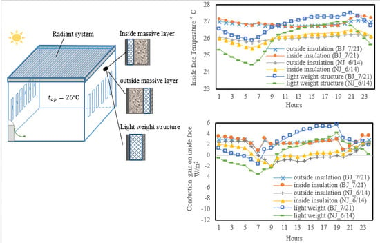
3.1.2. Performance on Typical Days in the Transient Season
On typical days in the transient season, the outdoor dry-bulb temperature ranges surrounding the rooms set the temperatures in Beijing and Nanjing. For a surface with a lightweight structure, the inside face temperature fluctuates with outdoor temperature both in a zone with an ESCS and a zone with an equivalent CAS (
Figure 8b). Both the inside face temperatures are higher than the corresponding zones’ operative temperatures during occupied period. The maximum conduction gains on these inside faces are close, occurring at 19:00 (
Figure 10b). However, the heat fluxes transfer from the inside faces to the outside in most of the unoccupied period, because the inside face temperatures decrease sharply as the outdoor temperatures fall down, and are even lower than the corresponding operative temperatures after midnight. In contrast, for the surfaces with heavy weight structures, the inside face temperatures have little fluctuation. The conduction heat gains on the inside faces are very minor, or even negative during the occupied period, but they increase as time goes on. The maxima occur at 5:00 when the zone operative temperatures are out of control (
Figure 10b). The phase lag times are prolonged by 10 hours compared to the performances on the surfaces with lightweight structures. Thus, the 24-hour conduction heat transfers on the external surfaces can be also regarded as the process of cooling charging when the cooling systems operate, and discharging in the rest time. That is the main reason why the values of relative effect of the thermal mass (R) are enhanced on typical days in the transient season.
Although almost all radiation heat gain in the zone with an ESCS can be extracted by a cooling surface through direct or indirect radiation heat transfer during the occupied period, the portion of conduction heat gain on the inside face of the external surface balanced by radiation is not as much as the one on a cooling design day (
Figure 9b), average 30% on a surface with lightweight structure and less than 10% on a heavy wall. This is due to the fact that the inside face temperatures of the external surfaces decrease as the outdoor weather becomes cooler. Even so, the inside face temperatures in the zones with ESCSs are relatively lower than the values on the surfaces with the same structures in the zones with CASs (
Figure 8b). The difference in heat transfer process between the zones with the different cooling systems leads to an interesting phenomenon on typical days in the transient season: the operative temperatures increase significantly when the CASs are switched off, and stay above the 26 °C during un-occupied period, whereas in the zones with ESCSs the operative temperatures rise slightly and then fall down after the internal heat gains completely disappear. Thus, similarly to the statement in [
5,
50], the application of night ventilation to cool down a surface with an interior massive layer could be feasible in a zone with a CAS. It may result in a considerable reduction in conduction gains, but it is not necessarily for a zone with a cooling surface. In addition, since a bigger difference exists between the inside face temperature and zone operative temperature in the zone with an ESCS, more conduction heat gain is observed by comparing it with the gain in the zone with an equivalent CAS. The values of relative effect of thermal mass (R) in the perimeter zones with ESCSs become less than the ones in the zones with CASs on the typical days in the transient season.
3.2. The Effect of Thermal Mass Position on System Performance
Preceding research [
13,
14,
15,
16,
17,
20] indicated that the insulation layer should be placed inside when the cooling system runs intermittently. Thus, the external wall structure can be rearranged (i.e., outside concrete + inside insulation). The corresponding thermal mass performances are discussed based on identical thermal environments in the same office building equipped with the combined system. The peak sensible cooling load decreases by approximately 2% to 3% as the thickness of the concrete layer extends from 0 to 200 mm, whereas the corresponding accumulated cooling loads for 24 h change minimally as the thermal mass increases.
Taking the performances in the north perimeter zones with ESCSs as examples, the inside face temperature on the surface with inside insulation approximates to the temperature on the surface with a massive layer inside during the occupied period on the Beijing cooling design day (
Figure 11). The conduction gains at these inside faces are also close (
Figure 12). Since the conduction heat gain only accounts for a small portion of the total gain in the thermal zone, the peak room cooling load reduces slightly as the thickness of outside concrete layer increases on the cooling design day. However, the accumulated conduction heat gain for the wall with inside insulation is higher than that for the surface with a massive layer inside, because the inside face temperature rises more significantly as the cooling system is turned off.
On a typical Nanjing day in June, more conduction gain exists on the external wall with inside insulation during the occupied period compared to the gain of the wall with outside insulation (
Figure 12), because little internal heat gain is absorbed by the inside insulation layer, and the portion distributed to the external wall immediately becomes the cooling load through convection and radiation heat transfers. In a typical office building, internal heat gain from occupants, lighting, and electrical equipment accounts for 60% or more of the total gain. Correspondingly, the inside face temperature on a wall with inside insulation is higher than that of the wall with a massive layer inside, most times, on the typical day in June. Although the temperature falls down after midnight, and the corresponding conduction gain decreases and becomes less than the gain on the surface with a massive inside layer, it cannot compensate the excess gain from 09:00 to 23:00 during the day. Therefore, the structure (outside massive layer + inside insulation) has little positive impact on the saving of heat transmission. The accumulated conduction gain on the inside face is close or even higher than the amount on the surface without concrete layer when the degree-hours are absolutely the same.
4. Discussion
Generally, a cooling source with a relatively higher temperature can be utilized by a radiant system, and the entire system coefficient of performance (COP) is expected to be better than a conventional CAS. The present authors investigated a practical TABS operation, and found that the supply water temperature can increase to some degree to maintain the indoor environment at an acceptable comfort level by utilizing the thermal mass and prolonging the radiant system operation time [
35]. In addition, from the performances on the typical days in the transient season, the transmission loads caused by an outdoor environment are not as much as the loads on the cooling design days, and the heat transfer in the inside massive layer can be viewed as a process of cooling charging and discharging. Therefore, a potential system strategy, OPPN, could be tried in the zone with ESCS. In the strategy, the auxiliary CAS still runs continuously during the occupied period; the hydronic system starts at midnight and runs continuously with a constant flow rate until the end of the occupied period. The supply water temperature is set at a constant value according to the average outdoor temperature over 24 h and the hydronic system operation hours. Thus, the room operative temperature cannot stay constant but should be in an acceptable range.
As illustrated by
Figure 13, during the period from midnight to the earliest occupied time, the inside face temperature of the external wall is relatively higher than the operative temperature in the zone (with ESCS in OPPN) on a Beijing cooling design day. As a consequence, the conduction gain on the inside face is considerably higher than the performance in strategy OPCT (
Figure 14), and it is the process for cooling conservation. During the occupied period, the inside face temperature approaches to the zone operative temperature, and the conduction is as low as zero, meaning that the conserved cooling releases to compensate the heat gain on this surface. Thus, the maximum heat gain on the cooling surface in strategy OPPN is not as much as the peak value in OPCT. Considering the effect of additional thermal mass on other structures in the zone, the supply water temperature can be raised from 16 °C (in OPCT) to 20 °C (in OPPN), and the peak cooling load of radiant system can fall down 28% in turn. In addition, the strategy OPPN can be also tried in the zone where the external wall has no concrete layer. However, as the
Figure 14 illustrates, little cooling can be conserved in the external wall, and the instantaneous transmission load is still close to the load in the same zone with ESCS in OPCT during occupied period. However, the risk of condensation should be avoided on the cooling surface by some measures when the single hydronic system runs in night.
Therefore, the cooling water temperature of the radiant system could be raised by taking the effect of internal thermal mass and improving the system’s operation strategy. Some low-grade cooling energy sources can be directly used for free cooling, such as geothermal systems. The geothermal system has been applied in several projects where radiant heating and cooling is employed [
32,
36,
51].
5. Conclusions
The effects of thermal mass in external walls were investigated by simulating the energy performances in a typical office building, rather than considering only the heat transfer for an individual structure. Operative temperature is employed to evaluate the thermal comfort level in both zones—those having a combined system and an equivalent CAS alone. The simulation tool of Energy-Plus is employed in the research, and it is based on heat balance method. It takes the influences of human actives and the cooling system operation strategy into account, in addition to the impacts of building physics and climatic conditions. Thus, the study results approximate real life and muse be the references for building and radiant cooling system designs, although the computation process is relatively complex.
The article introduces a new concept, relative effect (R), and takes the performance in the northern perimeter zone as an example with which to quantificationally distinguish the heat transfer process in the zone with an ESCS from the performance in the zone with an equivalent CAS, confirming that the cooling surface can decrease the heat storage capacity of the building envelope by radiation heat transfer [
29]. A big portion of conduction gain on an inside face of external walls is balanced by radiation heat transfer during the occupied period on cooling design days (e.g., 66% and 88%, respectively for the zone with heavy weight and the zone with light weight in the north zone). The research shows some new findings as follows.
The peak cooling load and the accumulated load of the combined system are higher than the corresponding values of the equivalent CAS by 9%–11% and 3%–4%, respectively, in the buildings of the same structure. The results are basically consistent with the findings from laboratory experiments [
49].
Compared to the performance in the zones with equivalent CASs, the effect of thermal mass is more evident in the zones with ESCSs on the cooling design days. The values of relative effect (R) are 22%–31% and 34%–40%, respectively, for the building with CASs and the building with ESCSs. The relative effects are about 60% and 45%, respectively, on the typical days in transient season.
An external wall with a massive inside layer is suggested for a zone with a radiant system either in intermittent operation or in continuous operation, because the inside insulation may lead to a greater transmission load, especially in a case with high internal heat gain (>60% of the total gain). The inside massive layer can also be used for cooling conservation in a different operation strategy (OPPN), and the peak cooling load of ESCS decreases 28%.
Based the results mentioned above, maintaining the thermal mass with a certain weight can be a key measure for a low-carbon building or green building, particularly in the zones equipped with radiant systems. In addition, the risk of condensation on cooling surfaces should be avoided, especially when the radiant system works in the situation without a dehumidification system running. In future work, some tests are going to be carried out to determine instantaneous heat fluxes on a cooling surface, and verify the interaction between a cooling surface and its surroundings.


