1. Introduction
Wind-diesel power plants (WDPP) are widely used for power autonomous consumers all round the world [
1]. The main components of the WDPP are a wind turbine and a diesel generator set (DGS). DGS provides guaranteed power supply to consumers, and the wind turbine can reduce fuel consumption and harmful emissions into the environment [
2]. However, commercially available WDPP have certain disadvantages like an excessive diesel fuel consumption during DGS operation, low efficiency, an incomplete use of a wind turbine at low wind speeds [
3].
The studies aimed at solving these problems can be divided into two main groups:
The first group includes studies devoted to determining an optimal quantity and capacity of the power units in the system of the WDPP. The article [
4] proposes a specific methodology for substantiating the parameters, placing and evaluating the WDPP effectiveness based on a multi-level system assessment of the resource potential and climate information. The article [
5] considers the influence of the share of the wind turbine generator capacity in the installed capacity in the WDPP and the composition of consumers on the amount of replacement of the DGS energy output. The article [
6] presents an optimal day-ahead scheduling of the WDPP and considers the role of battery storage system in frequency response. The optimal sizing of the PV/Wind/Diesel/Battery storage stand-alone hybrid system has been presented in the article [
7] to minimize the cost of energy supplied by the system while increasing the reliability and efficiency of the system presented by the loss of power supply probability. The article [
8] proposes a two-stage stochastic optimization framework to determine an optimal size of energy storage devices in a WDPP. The article [
9] introduces an optimization method that takes economic and technical indexes into account. The method optimizes the capacity of the battery and DGS under the premise of satisfying the technical indexes, and it also increases the capacity of the wind turbine and photovoltaic array by considering the economic index.
The second group includes studies on improving the WDPP efficiency. The articles [
10,
11] proposed an additional adaptive voltage compensation controller for static var compensator by using a double sliding-mode optimal strategy to maintain the system bus voltage stability. In the article [
12], a composite control strategy has been investigated for a photovoltaic, wind turbine, and DGS-based off-grid power generation system to achieve high performance while supplying unbalanced nonlinear loads. The article [
13] introduces a frequency regulation scheme to share the active power, not supplied by the wind power, among DGS with the aim of reducing the total fuel consumption of the DGS. The article [
14] presents a wind energy conversion system with a diesel generator. The proposed system regulates the loading of diesel generator to achieve low-specific fuel consumption.
The use of DGS with the variable shaft speed as a part of the WDPP is the most effective solution [
15]. As a rule, a change in the shaft speed depending on the load power is stepwise. This allows one to reduce specific fuel consumption by up to 20%. However, fuel economy can be increased by a smooth regulation of the speed based on the multi-parameter characteristic of the internal combustion engine (ICE) as a part of the DGS.
The multi-parameter characteristic is individual for each ICE; it has a nonlinear character and shows the dependence of specific fuel consumption on the shaft speed and pressure on the ICE piston. The multi-parameter characteristic varies depending on the external and internal ICE operating conditions. External working conditions for ICE are temperature, pressure, and humidity of ambient air, etc. Internal conditions are the brand and quality of fuel and the wear of ICE internal parts, etc. WDPP manufacturers do not provide information on such characteristics, as a rule. It is impossible to calculate a multi-parameter characteristic; it can only be obtained experimentally. There are no developments allowing an optimal selection of the ICE speed in the absence of a multi-parameter characteristic.
The aim of the research is the development of an intelligent control system for WDPP, which provides effective operating modes under changing external and internal working conditions.
The economy mode setting device (EMSD) has been proposed to be used as the basis of the intelligent control system. EMSD automatically calculates the value of the optimal speed of the ICE for the current value of the load power under changing external and internal conditions.
Section 2 describes EMSD.
Section 3 presents an algorithm of the intelligent control system.
Section 4 is devoted to simulation.
Section 5 describes the EMSD prototype.
Section 6 is devoted to the experimental research and discussion.
2. Economy Mode Setting Device (EMCD)
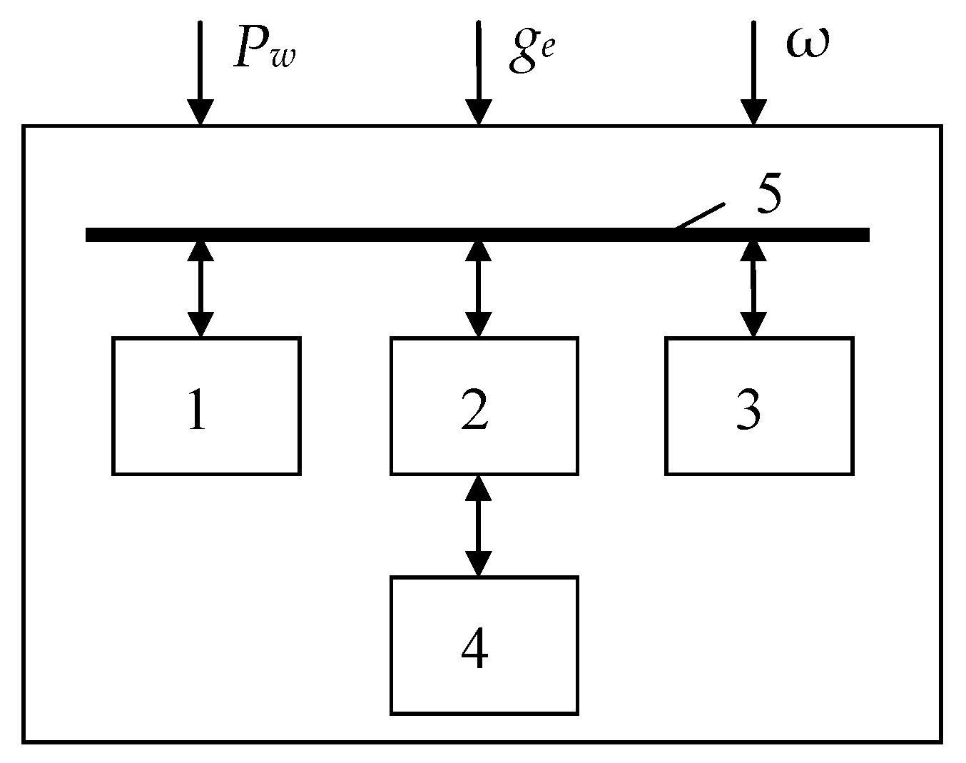
A functional chart of EMSD is presented in
Figure 1.
EMSD is an adaptive controller that uses the principle of artificial neural networks. EMSD consists of four main elements: a management controller, a learning controller, an associative memory block, and nonvolatile memory. A common information bus, providing bi-directional exchange of information and expansion of the system in the case of controlling multiple ICEs, combines the elements.
EMSD optimizes the speed of the engine shaft by controlling the ICE fuel supply depending on the internal and external working conditions. The control signal is generated using the associative memory block, which is a software model of an artificial neural network. The optimal ICE shaft rotation speed is determined in real time. The principle of EMSD operation is as follows.
The sensors record the following parameters: DGS power (P), ICE fuel consumption (ge), and ICE shaft speed (ω). These parameters are transferred to the learning controller, where they are compared with similar parameters available in the data memory block.
If the parameters of the current mode match to the parameters of one of the modes stored in the data memory block, the learning controller reads information about the position of the fuel pump rail (value h) and transmits it to the management controller. The management controller forms a control signal in the ICE fuel supply system. As a result, the fuel pump rail moves in the right direction by the required number of steps.
If the input data of the learning controller does not match to any mode stored in the data memory block, then the learning controller performs several learning cycles of the memory block. After training, a new optimal position of the fuel pump rail is formed, which is transmitted to the management controller. Additionally, parameters of a new mode are formed from the input (P, ge, and ω) and output (h) parameters, which are stored in the data memory block.
A block scheme of the neural network of the EMSD associative memory block is presented in
Figure 2.
The neural network of the associative memory block consists of three layers: input, hidden, and output. The input layer distributes the input data. The hidden layer consists of two neurons whose activation function is hyperbolic tangent. The signals of the neurons of the hidden layer are displayed linearly in the output layer. The output layer sums up the signals of the hidden layer and normalizes them. Neural network learning is implemented according to the algorithm of back error propagation, and it is realized by the learning controller.
At the beginning of learning process, the load power vector
Pload is applied to the inputs of the first layer of the network. At the outputs of the first layer, the following values are calculated:
where
is the input i of the neuron (j) of the layer n;
is the weight ratio of the corresponding neuron input;
Knorm is the normalization coefficient required to bring the load power value to the unit basis of the neural network;
Bi is the weight of additional input for the i-th neuron initialization;
M is the number of neurons in the layer n;
is the output i of the neuron (j − 1) of the layer n;
Pq is the component q of the input vector P; and
ωq is the component q of the output speed array ω.
For the output layer and the hidden layer
n, the error value (
δ) and the weight change (∆
Wij) are calculated:
where
dj is an ideal (desired) state of the neuron and
β is the learning coefficient.
Next, the values of the network link weights are corrected:
where
t is the number of the learning era of the associative memory block.
The value of the optimal rotation speed (ω
opt) is determined in the output:
where
xi1 and
xi2 are the inputs of the
i-th neurons of layers 1 and 2 of the neural network, respectively, and
Knorm is the normalization coefficient needed to reduce the load power value
P to the unit basis of the neural network.
The calculation continues until the network operation error (
Eω) becomes less than permissible. Network operation error is determined by:
where
ωt is an actual value of the rotation speed at the output of the neural network at the era t;
ωopt is an optimal value of the rotation speed at the output of the learning controller; and
p is the number of the learning era corresponding to the permissible error.
A necessary condition for the correct learning of the neural network is the presence of a learning set; that is, a set of logical pairs ωopt = f(P). A table array of speed values ωopt = f(P) for discrete values of power P is stored in a data memory block.
3. Algorithm of the WDPP Intelligent Control System
The WDPP intelligent control system consists of four modules:
A network learning management module
A module for determining the minimum fuel consumption of ICE
A control module for the optimal position of the ICE fuel pump rail
A module for managing associative memory and data memory of the neural network
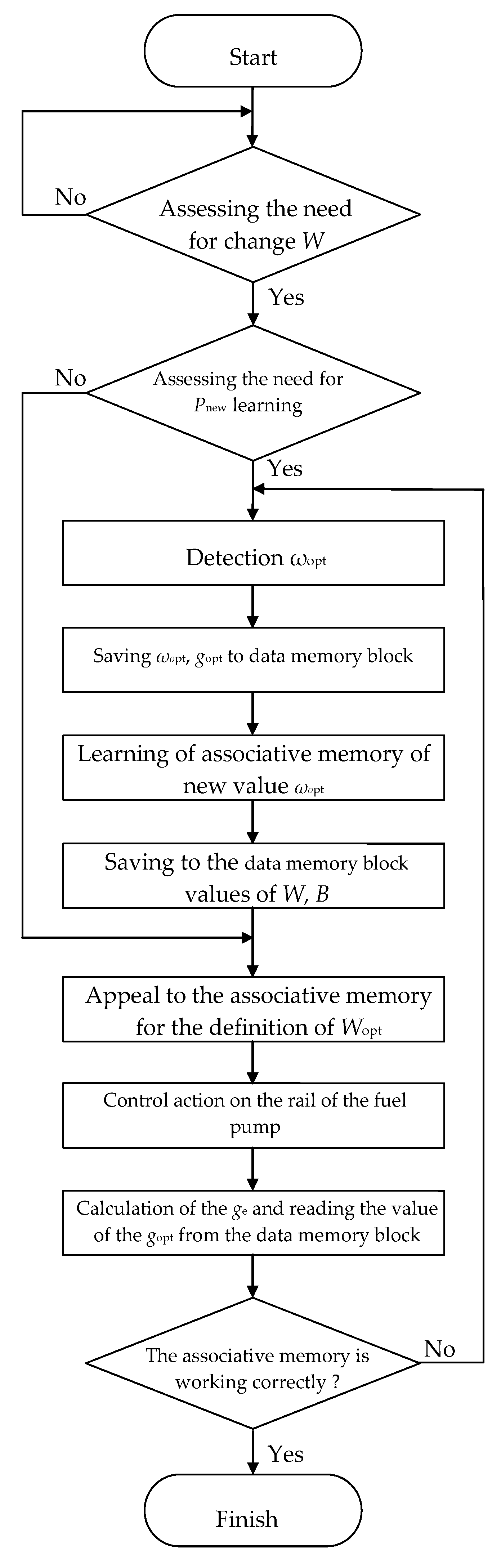
A block-chart of the algorithm of the WDPP intelligent control system is shown in
Figure 3.
The input data of the algorithm are an actual value of the DGS power (PDGS), an ICE fuel consumption (ge), a rotational speed of the ICE shaft (ωICE), and an actual value of the output power of the wind generator (Pw).
The management controller monitors change in the value of the load power during the WDPP operation. If the load power changes by more than a predetermined value Pstep, then a new value Pnew is fixed. Further, the management controller determines that the new power value belongs to the range of values stored in the associative memory block.
Based on the artificial neural network of the associative memory block, the optimal value of the ICE speed is determined. In accordance with the optimal value of the ICE speed, a control signal for the fuel pump rail h is generated. This provides an efficient mode of WDPP operation.
The developed algorithm significantly expands the limits of the efficient operation of the WDPP and makes the intelligent control system adaptive towards to the external and internal operating conditions of the ICE.
4. Simulation
A Simulink model of the WDPP has been created to test the developed algorithm. The Simulink model allows one to study the static and dynamic modes of WDPP taking into account the mutual influence of WDPP units on each other.
The model is built on the basis of differential equations describing the functioning of the main units of the WDPP:
A wind turbine, consisting of a turbine and a synchronous generator
DGS, consisting of a diesel engine and a synchronous generator
Energy storage systems
Three-phase active-inductive load
The block scheme of the Simulink model is in
Figure 4.
Mathematical models have been developed to simulate the operation of each WDPP unit. The models are differential equations that describe the processes of change of physical quantities such as current, voltage, frequency, torque, etc.
So, the operation of a synchronous generator as part of a wind turbine and DGS is described by a system of equations based on the law of electromagnetic induction and Ohm’s law [
16]:
where
Uabc is the stator voltage vector;
Ψabc is the stator flux distribution vector;
Rabc is the stator windings resistance vector;
Iabc is the stator current vector;
Hs is the matrix of independent circuits [
17];
Ux is the vector of the voltage across stator clamps;
ψf is the excitation winding flux distribution;
ef is the electromotive force of the excitation winding;
rf is the resistance of the excitation winding; and
if is the current of the excitation winding.
Differential equations allow one to determine the phase currents and voltages for static and dynamic modes of operation based on the initial parameters for a specific model of a synchronous generator. The detailed descriptions of the mathematical models of WDPP units and their study results are given in [
16].
A system of matrix differential equations has been developed to study WDPP operation modes, taking into account the mutual influence of WDPP units on each other:
Vectors Y with corresponding indices represent variable values describing the operation of the diesel engine (D), the synchronous generator (G), the wind turbine (W), and the load (E). Vectors Y are determined for each WDPP unit with appropriate mathematical models. So, the variables for the synchronous generator are the stator voltage and current vectors, which are determined by Equations (10). The variables for the diesel engine are the engine speed and the position of the fuel pump rail. The variables for the wind turbine are wind turbine power and torque.
All equations have been compiled in relative units that facilitate their joint integration. The basic values correspond to the nominal passport data of the elements [
16].
The algorithm of the WDPP intelligent control system for WDPP consisting of a 4 kW wind turbine and a 4 kW diesel generator has been tested on the Simulink model. Modeling was carried out for relative values of the load power in the range from 0.00 to 1.00 in increments of 0.05.
Figure 5 shows the obtained dependence of the ICE rotation speed on the load power
P.
Dots indicate discrete values calculated by using the learning controller. The solid line shows a continuous dependence ωopt = f(P) obtained with the associative memory block. The difference between the values ωopt, calculated with the associative memory block and the discrete values determined by the learning controller for the corresponding P values, does not exceed 0.03% of the nominal value of the ICE speed.
The research has shown that the developed algorithm of the WDPP intelligent control system provides a minimum error in determining the optimal ICE shaft speed.
5. Economy Mode Setting Device (EMSD) Prototype
An EMSD prototype has been developed. In addition to the learning and management controller, associative and data memory blocks (for generating a control signal), the prototype includes a block of parameters from measuring sensors (for obtaining initial data) and a stepper motor control unit (for changing the position of the fuel pump rail).
The appearance of the prototype is shown in
Figure 6.
Learning and management controllers are combined in one device (3), which is based on the TM4C123GH6 microcontroller. Its memory capacity is 256 kB, which makes it possible to store the control algorithm, process sensor signals, and also store intermediate data during the functioning of the neural network. To control the position of the fuel pump rail, a linear stepper motor (2) is used, which is connected to a programmable control unit (1). The control unit generates control pulses with a frequency of up to 10 kHz and an accuracy of 0.2%.
6. Experimental Studies and Discussion
The appearance of the test bench is shown in
Figure 7. The test bench consists of the following parts: (1 and 2) DGS and wind turbine simulators based on an asynchronous variable frequency drive and an alternator, (3) a DGS based on a gasoline ICE and synchronous generator, (4) connecting terminals for connecting a wind turbine, (5) an accumulator battery, (6) a programmable logic controller, (7) an autonomous inverter, (8) measuring equipment, (9) learning and management controller, and (10) programmable control unit.
Technical parameters of the test bench are shown in
Table 1.
The programmable logic controller (6) provides an overall control of the test bench. EMSD prototype is designed to control the operation of DGS simulator (1) and DGS with the gasoline ICE (3).
The EMSD prototype is connected to the frequency converter as part of the DGS simulator. Therefore, it is able to adjust the DGS speed. DGS simulator (1) and wind turbine simulator (2) are used for testing and tuning the software of the WDPP intelligent control system.
The main purpose of the EMSD prototype is to control the DGS based on a gasoline ICE and synchronous generator (3). The learning and management controller (9) as part of EMSD prototype receives information from the sensors about the DGS power, the ICE fuel consumption, and the rotation speed of the ICE shaft and determines the optimal value of the ICE speed according to the algorithm (
Figure 3). Information is transmitted to a programmable control unit (10), which forms a control signal for a linear stepper motor. The linear stepper motor changes the position of the ICE fuel pump rail according to the optimal engine speed. The placement of the learning and management controller, the programmable control unit, and the linear stepper motor as the part of the EMSD prototype is shown in
Figure 8.
Figure 8 shows: (1) the learning and management controller, (2) programmable control unit of the stepper motor, (3) ICE, (4) linear stepper motor, and (5) rail of the ICE fuel pump.
A test bench has been used to study the parameters of the WDPP operation modes with EMSD.
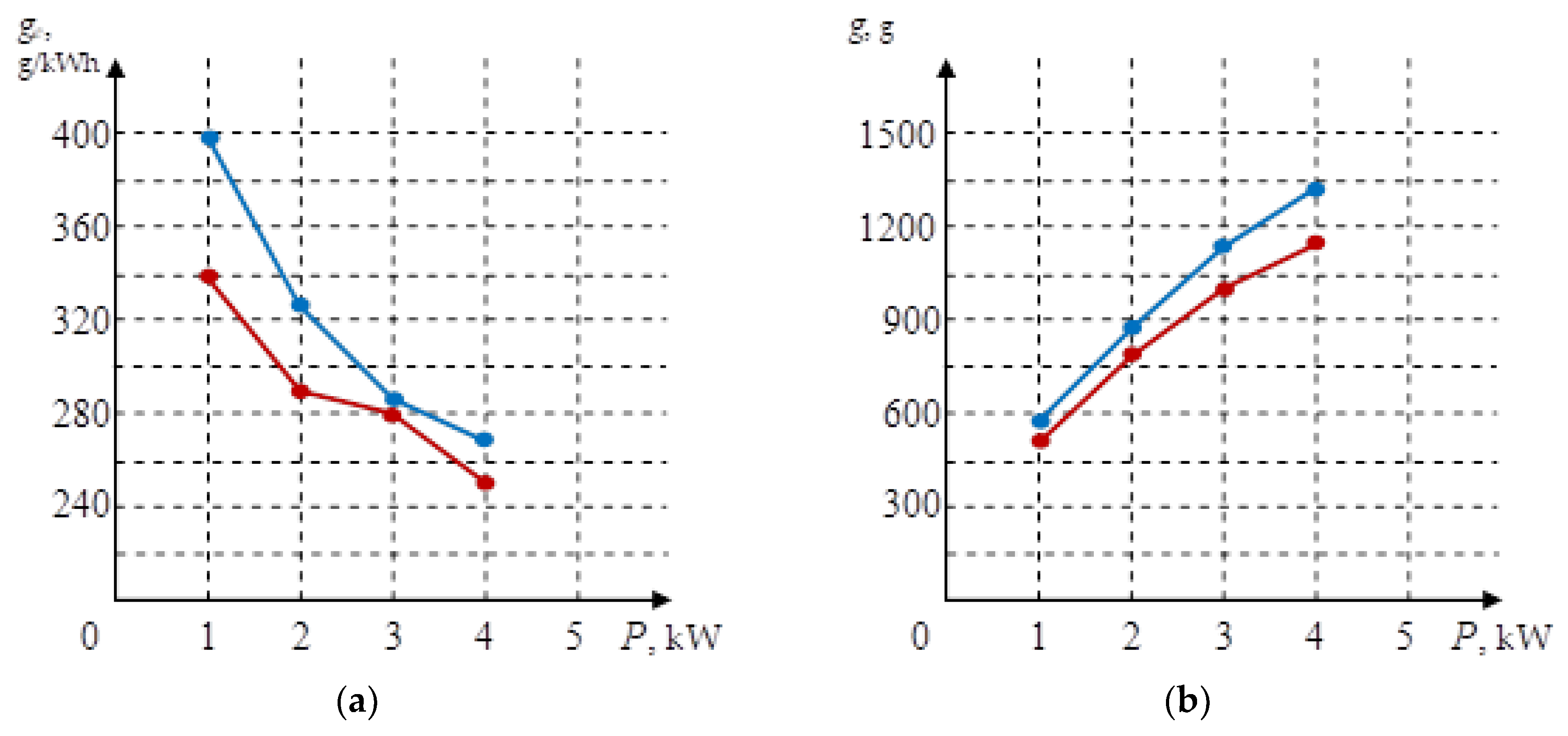
Figure 9 shows the dependences of the specific
ge (
Figure 9a) and absolute
g (
Figure 9b) fuel consumption of 4 kW DGS with variable rotation speed. The results were obtained by calculation (using the multi-parameter characteristics of the ICE) and experimentally (using the EMSD prototype).
In
Figure 9, the blue lines show the calculated characteristics, and the red lines show the experimental characteristics. The obtained results show that the error in determining the optimal engine speed using EMSD prototype is not more than 15%.
Figure 10 shows that the dependences of changes in specific (
Figure 10a) and absolute (
Figure 10b) fuel consumptions on the load power have been studied for two types of 4 kW DGS: with a constant (blue lines) and variable speed when using EMSD (red lines).
In the figures, one can see that the greatest difference in the fuel consumption corresponds to the mode of low loads. The difference in the fuel consumption is decreasing with an increase in the load power (
Figure 10). The fuel economy takes place due to the regulation of the engine rotation using EMSD and is the greatest with a load power of 1 kW and amounts to almost 30%.
Also, the research results have shown that the intelligent management system based on EMSD provides:
7. Conclusions
The article is devoted to solving the problem of the low efficiency of WDPPs.
An WDPP intelligent control system has been developed, which provides effective operating modes when changing external and internal conditions. It has been proposed to use the EMSD as the basis of the intelligent control system. The key block of EMSD is an associative memory block, which is a software model of an artificial neural network. Using this unit, the optimal ICE speed for the current load power value is automatically determined. The proposed approach allows one to expand the limits of WDPP effective operation.
The algorithm of the intelligent control system has been tested on the WDPP Simulink model. The simulation results have shown that the error in determining the values of the ICE shaft rotation speed does not exceed 0.03%. This confirms the high accuracy of the algorithm.
An EMSD prototype has been created. Research of the prototype has been conducted on a test bench consisting of simulators of a 4 kW DGS and 4 kW wind turbine. The research results have shown that the use of EMSD can significantly improve the efficiency of the WDPP. The error in determining the optimal engine speed using an EMSD prototype is not more than 15%. Diesel fuel economy in the low-load area was almost 30% for variable-speed ICE with EMSD compared with the constant-speed ICE.


