Review

Micro- and Macroscale Consequences of Interactions between CO2 and Shale Rocks

Petroleum Department, SINTEF Industry, 7031 Trondheim, Norway
*
Author to whom correspondence should be addressed.
Energies 2020, 13(5), 1167; https://doi.org/10.3390/en13051167
Submission received: 23 January 2020 / Revised: 25 February 2020 / Accepted: 2 March 2020 / Published: 4 March 2020
(This article belongs to the Special Issue Applied Geomechanics in Petroleum Engineering)

Abstract

:
In carbon storage activities, and in shale oil and gas extraction (SOGE) with carbon dioxide (CO2) as stimulation fluid, CO2 comes into contact with shale rock and its pore fluid. As a reactive fluid, the injected CO2 displays a large potential to modify the shale’s chemical, physical, and mechanical properties, which need to be well studied and documented. The state of the art on shale–CO2 interactions published in several review articles does not exhaust all aspects of these interactions, such as changes in the mechanical, petrophysical, or petrochemical properties of shales. This review paper presents a characterization of shale rocks and reviews their possible interaction mechanisms with different phases of CO2. The effects of these interactions on petrophysical, chemical and mechanical properties are highlighted. In addition, a novel experimental approach is presented, developed and used by our team to investigate mechanical properties by exposing shale to different saturation fluids under controlled temperatures and pressures, without modifying the test exposure conditions prior to mechanical and acoustic measurements. This paper also underlines the major knowledge gaps that need to be filled in order to improve the safety and efficiency of SOGE and CO2 storage.

1. Introduction

Shale rocks come in contact with carbon dioxide (CO2) when the latter is pumped underground either for CO2 capture and storage (CCS) or for shale oil and gas extraction (SOGE) purposes [1]. In the case of CCS, the shale typically acts as a caprock (sealing) that protects the CO2 stored in a reservoir underneath from escaping back to the atmosphere. In SOGE, the CO2 is used to enhance natural gas production. It can be used either during the stimulation stage as a fracturing fluid or at the secondary gas recovery stage as an extraction fluid displacing the natural gas and increasing the extraction efficiency. In this case, the CO2 is pumped directly into the shale formations (using shale as a reservoir).

1.1. Shale as a Caprock

Since approximately 1950, the concentration of carbon dioxide (CO2) in the atmosphere has increased abnormally. It is widely believed that this increase is one of the main causes of current global warming [2,3,4]. One of the solutions to combat this increase is to capture anthropologically emitted CO2 and store it in suitable reservoirs. Among the CO2 capture and storage (CCS) alternatives, geological sequestration in high porosity reservoirs is currently the most mature technology to efficiently combat climate change. The feasibility of CCS has been demonstrated in many successful projects (e.g., Sleipner and Snøhvit in Norway and Decatur in the USA [5,6,7,8,9]). The injected CO2 is targeted to stay underground for a minimum period of 1000 years, with a leakage rate of less than 0.1% per year [10,11]. Suitable sites are permeable reservoirs sealed by a nearly impermeable geological layer known as caprock. The role of the caprock in CCS is to protect the stored CO2 from escaping back to the atmosphere [12]. An ideal caprock should, therefore, be a non-porous, non-fractured, non-permeable, and non-reactive layer that will stay intact for eternity, unperturbed by changes in the chemistry of the surrounding fluids, the stress-field associated with injection, or tectonic movements. However, in practice, shale rocks available as caprock, even with extremely low permeability, are sensitive to changes in temperature and the chemical environment and remain susceptible to failure under certain stress conditions [13]. When injected into a reservoir, CO2 first displaces the reservoir pore fluid (water or brine), some dissolves in the pore fluid, and the rest remains as dry CO2. Through buoyancy forces, the injected CO2 migrates upward and forms a plume underneath the caprock [14,15,16,17]. The caprock may thus come into contact with dry or wet CO2, as well as CO2-saturated brine. The CO2-rich fluids can migrate through fractures and faults and interact with shale via the different mechanisms described in Section 3.

1.2. Shale as a Reservoir/Source Rock

In order to extract oil and gas stored in very low permeability shale formations, stimulation is required to increase the permeability of the rock for the faster and more efficient release of oil or gas. This is done through induced fractures around a horizontally drilled wellbore by pumping a fracturing fluid. Typical fracturing fluids are water-based [18]. However, due to the high water sensitivity of many shale formations (see Section 2.3), water-free alternatives are highly recommended [19]. One of the emerging alternatives is supercritical CO2 [20]. In this case, the CO2 is pumped directly into the shale formations. As discussed in the literature, there are several benefits to using CO2 as a fracturing fluid. The main advantages include: (1) elimination of harmful chemical elements, (2) mitigation of formation damages caused by water-based fracturing fluids and rapid cleanup, (3) simultaneous preferential CO2 adsorption over methane and thus enhanced gas recovery, and (4) storage of the greenhouse CO2 in the shale formations [21,22]. In order to optimize CO2 stimulation and storage processes in shale formations, a better understanding of CO2-shale interactions is needed.

1.3. CO2 Fluids in the Subsurface

Depending on the temperature and pressure in the reservoir, CO2 can occur in a gas, liquid, or supercritical state. In subcritical conditions, i.e., those below the critical point (a temperature of 31.1 °C and pressure of 7.38 MPa), CO2 occurs in a gas or liquid phase [23]. CO2 in its supercritical phase (above the supercritical point) has high diffusivity, low viscosity, a density close to that of a liquid, high reactivity, and a higher ability to dissolve other substances compared to gaseous or liquid CO2 [24,25].
The interactions between CO2-rich fluids and shale rock can lead to changes in the chemical composition (mineralogy), petrophysical (e.g., porosity, permeability), and mechanical (e.g., stiffness, strength) properties of the shale, which in turn may affect the shale’s performance as a sealing layer and the efficiency of shale oil and gas extraction operations. The goal of this review is to present the state of the art in research investigating the interactions between shale and CO2, to describe how the exposure of typical shale caprocks or reservoir rocks to reactive fluids, such as dry CO2 and CO2-saturated brine, will affect the chemical, physical, and mechanical properties of rocks. This is done by combining different investigations on various shale rocks, including experiments and modelling, and critically discussing the results. The recommendations are also highlighted for future studies in this area, especially on experimental procedures for mechanical tests. This paper is divided into three parts. The first part provides a thorough description of shale and its mineralogical, petrophysical, and mechanical properties. The second part describes the physical and chemical mechanisms between CO2 and shale. In the third part, the effects of these interactions on petrophysical (porosity, permeability, etc.) and mechanical (strength, stiffness, etc.) properties are described.

2. Shale Rock Characteristics

Shale is a laminated or fissile [26] fine-grained detrital sedimentary rock, formed by the consolidation of clay, silt, or mud (Figure 1) [27]; it is also the most abundant sedimentary rock on Earth [28,29,30]. In rock mechanics, shale can be defined as a rock where clay minerals form the load-bearing framework [31,32,33]; however, strictly speaking, freshly deposited clays are not shale. The lithological properties of shale (e.g., the textural properties, elevated capillary entry pressure, and ductility) are mostly controlled by the shale’s mineralogical composition [34]. Moreover, shales are highly inhomogeneous and anisotropic due to their fine laminations and the constitutions of different clay minerals.

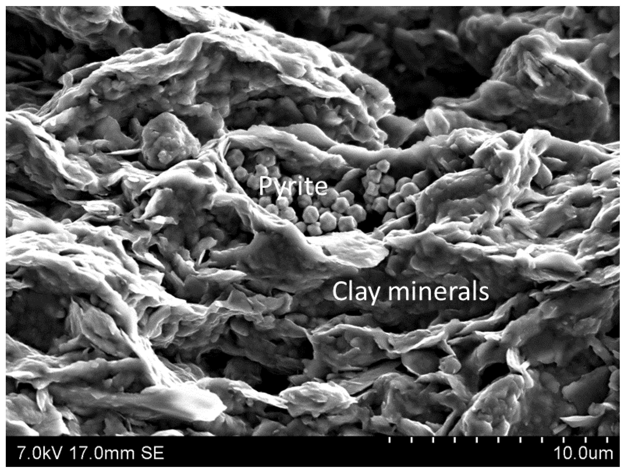
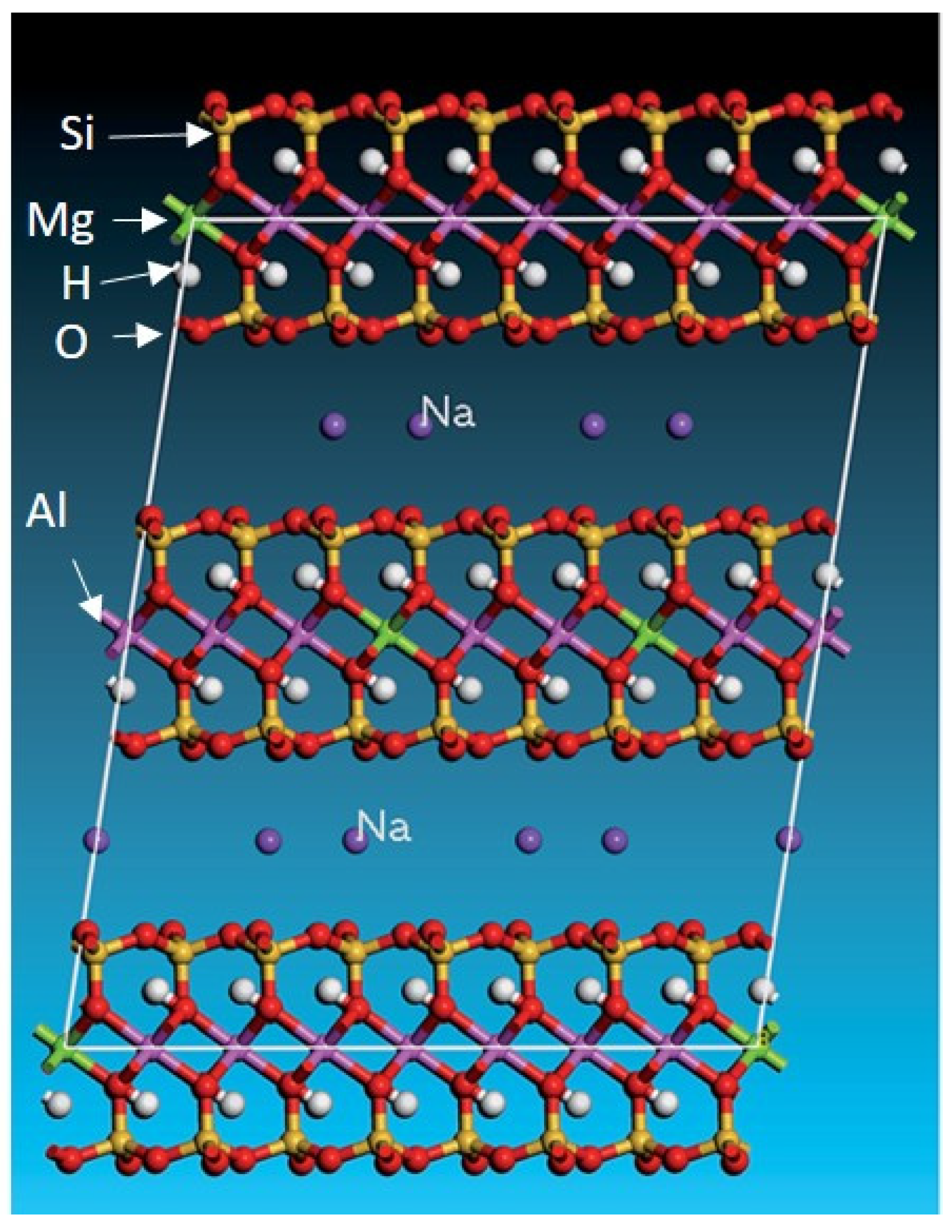
2.1. Mineralogical Properties of Shales

The complex and wide variety of composition types among shales can be attributed to their different sources (i.e., different rocks, reliefs, and climate), the degree of weathering (decomposition from the source rock and during transportation), the end-product of weathering and chemical interactions, and biochemical additions [26,35]. Moreover, the alteration of some clay minerals occurs due to chemical diagenesis with an increase in burial depth, creating greater complexity in shale composition. The composition of shale is dominated by clay minerals, which are mostly hydrated aluminium silicate with some replacement by iron and magnesium. Typical minerals in shale include (e.g., [26]) the following:
  • Kaolinite [ Al 4 Si 4 O 10 ( OH ) 8 ]
  • Smectite/montmorillonite [ ( Na , Ca ) 0.33 ( Al ,   Mg ) 2 Si 4 O 10 ( OH ) 2 n ( H 2 O ) ]
  • Illite [ ( K , H 3 O ) ( Al , Mg , Fe ) 2 ( Si , Al ) 4 O 10 ( ( OH ) 2 , ( H 2 O ) ) ]
  • Chlorite [~ ( Mg , Fe ,   Al ) 5 6 ( Si ,   Al ) 4 O 10 ( OH ) 8 ]
  • Quartz [ SiO 2 ]
  • Potassium/plagioclase feldspars [ KAlSi 3 O 8 ; ( Na ,   Ca ) ,   Al   ( Al ,   Si )   Si 2 O 8 ].
Other minerals include biochemical carbonates (e.g., calcite, dolomite) along with iron-bearing minerals (e.g., pyrite, siderite, and hematite). The presence of organic carbon makes certain shale formations potential petroleum (oil/gas) sources and/or reservoirs (gas shale). The exchange of cations in shales commonly occurs in clay minerals, which can be classified by their layered lattice structures. Two-layer (1:1) lattice structures contain one tetrahedral and one octahedral layer (Figure 2), whereas three-layer (2:1) lattice structures are made of one octahedral surrounded by two tetrahedral layers (Figure 3). These layer units are linked together by water or cations. The layer charge depends upon the substitution of cations in the tetrahedral or octahedral sheets [36]. Kaolinite group minerals generally have no (or very little) layer charge, whereas illite typically has a layer charge of less than 1 (0.7–0.9 per O10(OH)4). Smectite possesses a layer charge between 0.2 and 0.6 per O10(OH)4. Kaolinite is known as a neutral mineral, and its interlayer spaces are tightly bounded by hydrogen bonds, extending from exposed hydroxyl ions in the octahedral sheet of one layer to the oxygen layers in the tetrahedral sheet of the next layer. Almost no ionic replacement occurs at either the tetrahedral or the octahedral sheets in kaolinite.
In illite, the interlayer space is also bonded by two layers of water and large K+ ions, which are not easy to substitute. On the other hand, the interlayer space in smectite generally contains two layers of water and exchangeable cations (Na+, Ca+2). Due to the low layer charge in smectite, the smectite expands when it comes in contact with fluids with higher fluid activities and is substituted by the cation of preference (e.g., Ca+2 can be replaced by Na+). Smectite lattices shrink when native Na+ is replaced by K+ in its interlayer space.
Therefore, the cation exchange capacity depends on the degree of layer charge and chemical ability to exchange the cation in the interlayer space by foreign cations. The cation exchange capacity (CEC) of clay minerals ranges from 1–10 mequ/100 g for kaolinite to 80–150 for smectites and 120–200 for vermiculites [39]. Depending on the mineralogical composition of shale, its CEC values can differ significantly. However, cationic substitution takes place not only in the interlayer space but also at the tetrahedral or octahedral layer’s lattice. The transformation of clay minerals depends on the cationic transformation/exchange in the layer’s lattice, which appears to occur with exposure to appropriate conditions (e.g., pressure, temperature, and presence of a solution). As mentioned, shales also contain organic carbon. Most shales contain a small percentage (typically less than 10%) of organic matter. Organic matter is a source for a higher porous area within low porosity shales, but this porosity depends on the maturity of the organic matter.

2.2. The Petrophysical and Mechanical Characteristics of Shale

The petrophysical properties of shale include, among others porosity, permeability, grain size and shapes, and a specific surface area. The two most important parameters are porosity and permeability. Pore space (intrinsic void or fractures) are the storage sites for gas/liquid. The porosity of freshly deposited mud can be as high as 70% [40] and can be reduced to about 30% beyond a few hundred meters depth [41] and as low as below 10% at larger depths [42,43]. The porosity of shale depends on the depth of its burial (compaction), as well as its mineralogical composition, texture, and degree of diagenesis. The connective pores, along with existing fractures, create the pathway for fluid migration and thus contribute to the permeability of the rock. The physical and chemical interactions of fluids with shale strongly depend on the shale’s porosity and permeability. Therefore, it is worthwhile to understand permeability when analysing any effect of fluid (such as CO2) on argillaceous rocks, such as shale. Unfortunately, it is very difficult to achieve reliable permeability measurements for shales, given their fine pore sizes and complex structures [35,44,45]. In addition, the permeability relative to different fluids (gas or liquids) is different for the same rock sample. Shales exhibit very low hydraulic permeability, and this value varies widely, ranging from nanoDarcy (nD) to microDarcy (µD) [46]. The equation derived by Kozneny [47] and later modified by Carman [48] indicates that permeability is a function of porosity, fluid viscosity, grain size and shape, tortuosity, the pressure gradient across a cross-section, and the specific surface area. However, for CO2 storage integrity, scale-dependent permeability may be worthy of note. Many laboratory-derived permeability measurements underestimate the large (reservoir) scale permeability [49], which can be attributed to the existence of fractures and non-clay minerals [45]. Scale dependency has also been reported by several authors (e.g., Bredehoeft et al. [50], Rudolph et al. [51], and Keller et al. [52]). However, Neuzil [45] showed that the permeability scale-dependence in argillaceous rocks is not present at an intermediate scale, but it may be present at very large regional scale. It is also important to study the fracture network of the sealing material since there is field evidence (e.g., [53]) of fluid movement through fracture networks, which may even lead fluids all the way up to surface (e.g., Bond et al. [54], Ingram and Urai [55], and Lewicki et al. [56]).
A few more physical or mechanical characteristics of shales are worthy of mention, such as capillary entry pressure, strength, stiffness, acoustic velocity and anisotropy [57] (acoustic and strength), wettability, etc. As mentioned earlier, capillary entry pressure is one of the most important properties to ensure that shale is sealed and to quantify the maximum height of the injected CO2 column that can be held in the reservoir [34,58,59]. A higher capillary entry pressure of shale restricts the movement of the fluid (e.g., CO2), which in turn restricts the available space for the fluid to react with the shale [59]. The potential leakage of CO2 through caprock could occur by diffusion, capillary breakthroughs, or by fracture flow; among these mechanisms, the latter two dominate [60,61,62]. These seepages could create potential available space for CO2–shale interactions inside the shale formation (the seal), in addition to the contact area between the seal and the reservoir. The capillary entry pressure is directly related to the permeability of the shale material, the interfacial tension between the shale wetting fluid and the non-wetting fluid, and the cation exchange capacity [63]. The very low permeability, very small pore throat radius, and higher cation exchange capacity of the shale contribute to a very high capillary entry pressure for any non-wetting fluid to enter into the generally water-wet shale [55,63,64]. The fluid-flow and fluid-recovery efficiency in shale reservoirs can also be affected by shale wettability [65,66,67]. However, the wettability of shale is still ambiguous, ranging from oil-wet to water-wet [66]. This can be modified by the interplay of various factors, such as pH, temperature, and surface access [67]. Since fine-grained sediments (mud/shale) are deposited in a marine environment, the shale is expected to be water-wet [68]. However, the presence of mature organic matter may cause local oil-wet patches [69].
Among the many characterization parameters, stiffness, strength, and acoustic velocities will be briefly discussed in this review article. These parameters are generally related to the porosity, density, mineralogy (mainly clay content), and heterogeneity of shale materials. Stiffness is a very important parameter in geomechanics to understand the deformability of rock and can be obtained from static (stress–strain) or dynamic (acoustic velocities) measurements. The stiffness parameter can bridge the geomechanical parameters and seismic parameters (velocity). The number of stiffness parameters needed to define a rock depends on the rock’s anisotropy. For an isotropic linear elastic material, only two parameters are required to characterize the material: Young’s modulus and Poisson’s ratio or the shear and bulk moduli. However, when the material is anisotropic, the number of stiffness parameters increases significantly (to a maximum of 81). However, shale can be approximated as a transversely isotropic (TI) material where the properties of the rock are similar in two horizontal axes (x- and y-axis) but different from its vertical axis (z-axis) (e.g., x = y ≠ z). The number of the stiffness parameter in the case of TI is 5 (for more details, see Fjær et al. [31]). Very few articles have reported the effects of CO2 on stiffness parameters. Both the Young’s modulus and Poisson’s ratio were investigated by Agofack et al. [70] and Espinoza et al. [71], but only changes in Young’s modulus was reported by Lyu et al. [72]. More detailed discussions on CO2‘s effect on shale stiffness are presented in Section 5.2.
The strength of the shale is very important, not only to understand how difficult the shale is to break but also for seal integrity evaluation, well planning, wellbore stability, reservoir compaction, and surface or sea floor subsidence, which has been found to be sensitive to the internal properties of rock or external factors such as composition, organic content, pore pressure, and stress history (e.g., Dewhurst et al. [42]). The strength of shales varies with the direction of measurement (anisotropy), e.g., shales are the strongest at 0° with the bedding direction (measuring the strength across the bedding) and are the weakest at 45–60° with the bedding direction. Strength parameters include UCS (unconfined compressive strength), shear strength, and tensile strength. For more discussions, with a few examples of the effects of CO2 on shale strength, please see Section 0.
Anisotropy is one of the most widely studied properties (yet to be understood perfectly) of shale. When a rock property (e.g., strength, acoustic velocity, or permeability) varies with the direction of measurement (angle of measurement) with respect to a fixed orientation (e.g., bedding), the sample is said to be anisotropic in that property (e.g., it can have velocity anisotropy or fracture anisotropy). Shales show two types of anisotropy: intrinsic (lithological anisotropy, developed from the preferred orientation of platy clay minerals and the development of thin lamination) and stress-induced anisotropy (anisotropy developed with an increase in stress). There are many articles in the literature discussing strength anisotropy (e.g., Jin et al. [73], Fjær and Nes [74]), where the variation of the strength of the rocks with the angle creates problems, especially in inclined wells (e.g., borehole stability). Few researchers have discussed the effects of stiffness, strength, acoustic velocity, and even fracture anisotropy on CO2 storage or seal integrity. Bond et al. [54] discussed the influence of fracture anisotropy on CO2 flow. Cheng et al. [75] and Armitage et al. [76] investigated the effects of permeability anisotropy on buoyancy driven CO2 flow. Al Ismail et al. [77] investigated the effects of CO2 adsorption on permeability anisotropy. Taheri et al. [78] made an attempt to investigate the effects of anisotropy and heterogeneity in both the horizontal and vertical directions of layering on the CO2 dissolution in a saturated porous medium with brine using simulation methods. Lu et al. [79] reported anisotropic strain in response to CO2 injection, where the strain is always smaller in the direction parallel to the bedding plane.

2.3. Water Sensitivity of Shale Rocks

The main cause of the water sensitivity of shale formations is the presence of swelling clays in their composition. The most common type of swelling clay is smectite. Smectite’s structure consists of 2:1 layers consisting of an octahedral hydroxide sheet sandwiched between two opposing tetrahedral silicate sheets [80]. When the fluid molecules are adsorbed into the interlayer, the interlayer distance d001 increases and induces swelling of the material. Ferrage [80] considered four hydration states for smectite:
-
Dehydrated state (d001 ~ 9.6–10.7 Å; 0W: no complete water layer);
-
Mono-hydrated state (d001 ~ 11.8–12.9 Å; 1W: one complete water layer);
-
Bi-hydrated state (d001 ~ 14.5–15.8 Å; 2W: two complete water layers);
-
Tri-hydrated state (d001 ~ 18.0–19.5 Å; 3W: three complete water layers);
where Å refers to Ångström (1 Å = 0.1 nanometer). The exposure of shale to fluids with compositions even slightly different from those of in situ pore fluid induces a difference in chemical potential and changes the swelling pressure [81]. Under constant strain conditions, the increase of pressure due to adsorption-induced swelling can be as high as a hundred MPa up to a few GPa [82,83]. If the swelling pressure along with the pore pressure exceed the in-situ stress and particle cementation forces, shale failure will occur.

3. Interactions between CO2 and Shale

3.1. Processes at the CO2/Brine Interface

When dry CO2 is pumped underground, it comes into contact with the reservoir brine. Two processes take place at the brine/CO2 interface: (1) Water present in the brine evaporates to the CO2 phase [84], and the concentration of salts in the brine increases. With the progressive evaporation of water, the brine becomes oversaturated with salts, and salt precipitation may occur. (2) CO2 dissolves in brine. The dissolved CO2 reacts with water to form carbonic acid, which partially dissociates and forms carbonic (CO32−), bicarbinate (HCO3), and hydrongen (H+) ions. Due to these dissolution and dissociation processes, the pH of CO2-rich brine drops. The pH value at equilibrium depends on the partial pressure of CO2 and on the temperature and salinity of the brine [85,86,87]. These acidic conditions of the pore fluid have the potential to affect the composition of the rock matrix. In addition to CO2-rich brine, dry CO2 can also affect the rock microstructure and its mechanical properties via different mechanisms. These interaction mechanisms are described below.

3.2. Shale in Contact with Dry CO2

3.2.1. Drying

At the dry CO2/brine interface, water evaporates and mixes with the CO2 phase. Under downhole conditions, this evaporation and mixing lasts until the CO2 becomes saturated with water (i.e., reaches equilibrium). The thermodynamics of water partitioning in equilibrium with CO2 have been described by Spycher et al. [86,88]. The water absorption into CO2 leads to drying of the surrounding formation fluids [89,90,91,92,93,94]. This drying may affect both the brine present in the pore matrix and the rock matrix itself. The continueous drying of brine, filling pore spaces in the rock matrix, often leads to the oversaturation and precipitation of different minerals in the matrix. It has been found that drying and concommitant salt precipitation may lead to the clogging of an initially very permeable pore matrix, which may eventually result in injectivity problems [89,95,96]. The permeability of nonfractured shale rocks is usually very low, but, as fractures are very abundant in shale rocks, the overal permeability of fractured shales can be significantly affected by the drying and concommitant salt precipitation processes. More specifically, fractures serving as flow conduits may be clogged by the precipitating salts. Nooraiepour et al. [97] studied how fractures in Draupne shale (primary caprocks for Smeaheia CO2 storage in Norway) clog upon CO2 induced salt precipitation. The authors showed that the CO2 phase influences the magnitude, distribution, and precipitation patterns of the salt in fractures. The injection of gaseous CO2 resulted in larger salt precipitation compared to both the liquid and supercritical CO2. Miri et al. [92,93] demonstrated the importance of capillary forces on salt precipitation. It has been suggested that drying-induced salt precipitation may have fracture sealing potential [97]. However, it remains unknown whether salt precipitation has any effect on the mechanical properties of shale rocks close to fractures and to to what extent it influences fracture propagation.
Not only interstitial brine but also the rock matrix itself may be affected by drying. Drying may cause rock dessication. It is known that shale dehydration will lead to structural changes like shrinkage and cracking within the shale matrix [24]. This occurs as a consequence of the dehydration of clays, which tends to respond, under volumetric changes (swelling or shrinkage), to changes in brine/water content (wetting and drying) [25]. The integrity and strength of Pierre shales were found to be deterioted by submitting the samples to successive wetting and drying cycles [26,27]. Mugridge and Young [98] observed significant deterioration of mechanical properties, despite negligable mineralogical changes. A reduction in size of the clay aggregates was suggested to contribute to the observed residual strength decrease [27]. The above-described observations were made under ambient conditions. The effect of dry CO2 on shale dessication and the possibly-induced changes in the mechanical properties of shales under realistic downhole stress conditions seem to be neglected in the literature and are perceived by the authors as a knowledge gap that needs to be filled in order to obtain a better understanding of the interactions between dry CO2 and shale reservoirs or caprocks. This knowledge gap has already been highlighted by Gaus [28], who suggested using mass balance calculations to answer the question of whether, and under which CO2 injection conditions, the dessication of the caprock may impair its integrity.

3.2.2. Dissolution of Organic Matter

Another physical process that may affect the microstucture, and thus the mechanical properties, of shale is the dissolution of organic matter (i.e., kerogen) present in the shale matrix. Kerogen is the major organic component of shale rocks and consists of a complex mixture of organic materials. Under a supercritical state (a temperature and pressure higher than 31.1 °C and 7.2 MPa, respectively), CO2 has been demonstrated to be an excellent solvent for organic compounds [99]. Supercritical CO2 has a density and dissolving ability similar to those of liquid CO2, while its diffusivity, viscosity, and surface tension are comparable to those of gas [100]. As such, supercritical CO2 offers the efficient dissolution and mass transfer of dissolved components [101]. CO2 is a nonpolar solvent and thus it dissolves readily nonpolar molecules [102]. The dissolution of polar oil components in supercritical CO2 was, however, enhanced in the presence of polar solvent additives like methanol [102]. In addition, it has been shown that supercritical CO2 can partially dissolve the kerogen present in shale rocks [100,103]. The supercritical extraction efficiency of kerogen was found to be related to the mineralogical composition and microstructure of shale rocks and was higher for carbonate rich shales [102]. The corelation between kerogen dissolution and changes in the porosity, permeability, and mechanical properties of shale rocks has not yet been well established. It is thus unclear how the long-term exposure of organic matter-rich shales to supercritical CO2 can affect their mechanical stability.

3.2.3. Sorption of CO2 on Shale Rocks

This phenomenon has been extensively studied both in the context of enhanced oil and gas recovery and in the context of CO2 sequestration [20,104,105,106,107,108,109,110]. Heller and Zoback [111] compared the sorption capacity of CO2 and that of methane on clay minerals (kaolinite and illite) and carbon as a model for shale components. The authors found that the sorption capacity of CO2 on both minerals and organic matter was 2–3 times higher compared to methane. According to Nuttall et al. [112] and Kang et al. [105], the difference in the sorption capacity between CO2 and methane can be up to 5–10 times depending on the shale type. Upon the adsorption and absorption of CO2, shales undergo volumetric changes [79,111], which are proportional to the amount of adsorbed CO2. For a given amount of adsorbed gas, the magnitude of swelling observed for different shales and shale components is different. The difference in swelling capacity has been attributed to the difference in the stiffness between materials (i.e., the stiffer the material was, the smaller the volume change that was found) [111]. The complexity of the swelling mechanisms of shales upon the adsorption of CO2 arises from the chemical diversity of shale components. Shale components can adsorb and absorb CO2 in both physical and chemical manners known as physi- and chemisorption. Figure 4 schematically illustrates the adsorption of CO2 at mineral grain surfaces, as well as its absorption inside organic matter and clay mineral grains under true dry conditions. The deformation of clay particles and organic matter upon the adsorption of CO2 is probably the main contributor to global shale volumetric changes when the shale is exposed to CO2 [111,113,114]. It has been shown that the spacing between the crystalline structure of clay sheets increases upon adsorption of CO2 [115]. For example, for a single hydrated Na-montmorillonite (with original spacing of d001~12.4 Å), the spacing increaed by 0.5 Å, which resulted in a 4% expansion in the direction perpendicular to the clay sheets [116]. The expansion determined for Na montmorillonite clays initially containing a higher fraction of water in the interlayer region has been reported to reach 9% [117]. The magnitude of this so called “crystalline swelling” is also dependent on the type of cation present in the interlayer [115]. Therefore, it is expected that the magnitude of clay swelling inside the shale matrix will be a result of CO2 adsorption and possible concomitant ion exchange processes.
Molecular dynamic simulations show that the organic matter present in shale rocks (kerogen) undergoes non-negligable deformation upon CO2 uptake [113,118]. Ho et al. [118] suggest that strong chemo–mechanical coupling exists between the gas sorption and mechanical strain of a kerogen matrix. The authors showed that the kerogen volume can expand by up to 11% upon CO2 adsorption at around 19 MPa and that gas uptake is enhanced by kerogen swelling [118]. It has also been suggested that the CO2-induced swelling of clays and kerogen may contribute to the sealing of small fractures and thus to a reduction in the permeability and improved sealing capacity of swelling clay-rich shale rocks [117,119]. However, this hypothesis needs to be experimentally validated. The magnitude of net shale swelling will depend on the ratio between the total content of swelling matter (i.e., the swelling clays and kerogen) and nonswelling matter (e.g., quartz and nonswelling clays) in the shale matrix. The effect of CO2 sorption-induced swelling on the mechanical properties of shale is, however, unknown. The main difficulty remaining is to decouple sorption from other physicochemical processess (such as the dissolution of minerals) that occur within shales during their exposure to CO2 or from the processes of pH-induced swelling.

3.3. Shale in Contact with CO2-Saturated Brine or Wet CO2

3.3.1. Dissolution of Minerals

When shale comes in contact with CO2-saturated brine or wet CO2, the carbonic acid present in the solution starts diffusing into the shale’s pore space. In shale’s composition, there are always some minerals susceptible to carbonic acid’s effects. These minerals may be dissolved and eventually leach out. Shales may have very diverse mineralogical compositions (see Section § 0), but they are most often comprised of quartz, feldspar, clay minerals, carbonates, iron oxides, and other minerals, as well as organic matter (kerogen) [120]. All these minerals can, to some extent, react with acid under very different dissolution rates.
Poorly water soluble carbonates like calcite (CaCO3), dolomite (CaMg(CO3)2), magnesite (MgCO3), and siderite (FeCO3) are very susceptible to acid attack and react rapidly with carbonic acid according to Equation (1):
MeCO 3 + H + Me 2 + + HCO 3
As a consequence of this reaction, carbonate is dissolved, protons are consumed, pH increases, and both metal ions (Me2+) and bicarbonate ions (HCO3) are released into the solution. Lahann et al. [121] showed that carbonate dissolution was one of the first responses resulting from the injection of CO2 into the New Albany Shale reservoir [121]. The dissolution rates of calcite, dolomite, and magnesite in CO2-saturated aqueous solutions at partial CO2 pressure up to 5.5 MPa (pH between 3 and 6) have been well described by Pokrovsky et al. [122] and Golubev et al. [123]. The dissolution rate was found to decrease in the following order: calcite > dolomite > siderite > magnesite [123]. As the carbonate dissolution rates are relatively fast at pH conditions relevant for storage and fracturing, the reactivity of low permeability shales will be, in most cases, transport-controlled. The dissolution and reaction of CO2 with water, the dissociation of acid, and the diffusion of the dissociated acid to a carbonate substrate are the limiting factors in carbonate leaching [87]. Therefore, any increase in the porosity and permeability of the shale matrix will facilitate carbonate leaching [124]. Carbonate leaching from shale rocks upon exposure to CO2-saturated brine has been reported by many authors [124,125,126,127]. Armitage et al. [128] exposed “In Salah” caprock samples to CO2 saturated brine and showed that the caprock experienced a significant increase in porosity and permeability due to the dissolution of its siderite and chlorite minerals. More interestingly, Sanguinito et al. [129] observed the carbonate dissolution in Utica shale upon exposure to dry CO2. They showed that the presence of interstitial pore water is enough for carbonation processes to occur in shale. Recently, Goodman et al. [130] showed that, by comparing unexposed exposed outcrop Utica Shale samples, both the porosity and the surface area (m2/cm3) significantly increased when exposed to CO2 and that this effect is higher when exposed to a H2O + CO2 solution. Performing relatively similar experiments on Marcellus Shale samples, Kutchko et al. [131] showed that exposure to CO2 decreases the BET surface area and porosity of a downhole sample; the effect on the outcrop sample was also significant, but sometimes showed an opposite trend. Thus, the physicochemical and mechanical changes in shale rocks saturated with brine exposed to both wet and dry CO2 should continue to be addressed.
Phyllosilicate minerals are also susceptible to carbonic acid attack. They present a wide range of chemical constituents, including smectites, kaolinite, serpentine, talc, mica, illite, and chlorite minerals, but the common feature for all phyllosilicates is their layered nature. Due to this sheeted structure, their specific surface area is large, which increases their reactivity. In most cases, the dissolution of phyllosilicates is sensitive to pH and increases with a decreasing pH in an acidic environment [87]. Therefore, reactivity increases with an increase in partial CO2 pressure. The reaction of chlorite, as an example of a phyllosilicate mineral, in the presence of water and carbonic acid is described in Equation (2). Due to the complexity of the structures and pathways by which the dissolution of chlorite and other phyllosilicates may proceed, only a generalized reaction is presented [132,133]:
( Fe , Mg ) 5 Al 2 Si 3 O 10 ( OH ) 8 + 8 H + 3 SiO 2 ( aq ) + 2.5 Fe 2 + + 2.5 Mg 2 + + 8 H 2 O + 2 AlO 2
Chlorite dissolution releases silica, iron, and/or magnesium and aluminate ions into the solution. In contrast with other phyllosilicates, the chlorite dissolution rates were found to be independent of pH, with a pH range between 4.2 and 5.3 [132]. Feldspar undergoes hydrolysis, as outlined in Equation (3):
2 KAlSi 3 O 8 + H 2 O + 2 H + +   CO 3 2 2 K + + CO 3 2 + Al 2 Si 2 O 5 ( OH ) ( s ) + 4 SiO 2 ( aq )
The substrates of K-feldspar hydrolysis in the presence of carbonic acid are potassium carbonate, silica dissolved in water, and solid kaolinite [134]. Thus, during the hydrolysis reaction, soluble elements (potassium carbonate and silica) are leached out of the rock; only the insoluble kaolinite is left behind. Similar to the reaction with carbonates, feldspar hydrolysis leads to the consumption of acid and the neutralization of pH. The long-term reactive transport modelling of CO2 in the Nordland Shale caprock at Sleipner, performed by Gaus et al. [135], shows that carbonate dissolution initially dominates, but, in the long term, feldspar alteration is the dominant reaction.
In contrast to carbonates and silicates, the dissolution of quartz is a slow process under CO2 storage or fracturing conditions. According to Knauss and Wolery [136], the dissolution rates of quartz are independent of pH for pH values lower than 6. This means that increasing CO2 pressure and thus decreasing pH will not facilitate quartz dissolution [87]. The relatively small quartz grain surface area compared to, for example, feldspar can further slowdown quartz’s dissolution in CO2-saturated brine. Consequently, the effect of CO2-saturated brine on quartz is usually assumed negligible.

3.3.2. Precipitation and Reprecipitation of Minerals

The reactions of carbonates and other minerals with CO2-saturated brine leads to the consumption of proton and thus increases the pH of brine. Along with these pH changes, metal ions are released to the solution, as described in reactions (1)–(3). At relatively high concentrations of metal ions, this increase of pH may lead to the reprecipitation of some minerals [135,137]. The reprecipitation of dolomite, ankerite, siderite, and iron hydroxide was experimentally shown to take place in shales exposed to dry CO2 or CO2-saturated brine [121,129,138]. Kampman et al. [138] examined caprock samples recovered from a natural CO2 reservoir. This reservoir was located at a shallower depth and had a lower pressure than that encountered in reservoirs for geological carbon storage. However, since the reactions between the minerals and CO2-saturated brines are only slightly affected by pressure, the authors were able to assess the long-term impacts of CO2-rich fluids on caprock integrity. The authors showed that the caprock, at its interface with the reservoir (up to 7 cm), was depleted of hematite and primary dolomite and that the minerals were reprecipitated in the form of ankerite–dolomite, pyrite, and gypsum. The authors concluded that reprecipitation delays the propagation of the reaction front, which reduces the penetration of carbonic acid into the caprock. It has been suggested that precipitation or reprecipitation of the dissolved minerals within the shale matrix may also lead to the so-called “self-sealing of fractures” and to caprock strengthening [139]. The effects of mineral dissolution and reprecipitation on the pore system and permeability of shale have not yet been well described.

4. Effect of CO2 on Petrophysical Parameters of Shale

This section focuses on the changes in some selected petrophysical parameters of shale after exposure to CO2. It is also important to recall the different states of CO2 while talking about the interactions between CO2 and shale. Pan et al. [140] showed that supercritical CO2 has a significantly greater effect on shale than subcritical CO2. The effects of CO2–brine–shale interactions on porosity, permeability, pore size, and surface area have been reported by several experimental studies [141,142,143,144,145,146,147]. These interactions trigger dissolution, precipitation, and migration of fine clay grains, which can open or close the pore throats [148]. On the one hand, studies have revealed an increase of total porosity and connective porosity upon CO2 exposure [140,142,144]; on the other hand, a decrease of porosity and connective porosity/matrix permeability was also reported [140,142,145,146,148,149,150]. The increase in pore volume may be related to the decrease in capillary threshold pressure [144]. However, Lahann et al. [121], Okamoto et al. [151], and Gaus et al. [135] reported that there was no, or very little, change in shale’s pore structure upon CO2 exposure. Wu et al. [145] explained that this reduction in permeability was dependent on permeability’s initial value in shale and the effective stress. Pan et al. [140] investigated a broad range of pore structure parameter changes under sub and supercritical CO2 exposure. It is difficult to highlight a single parameter behind the mechanism that decreases or increases the total porosity, pore diameter/width, and connective porosity under CO2 exposure (especially supercritical CO2). Dissolution and adsorption-induced expansion are the two most important mechanisms able to alter the pore structure during the interactions between subcritical CO2 and shales, but these mechanisms may play different roles in pore structure modification [140]. On the one hand, geochemical reactions dissolve and destroy the internal structures of minerals, leading to nanopore enlargement; on the other hand, adsorption-induced expansion leads to volumetric changes, which may alter the pore structure and ultimately narrow the pores [145,146,152]. Lu et al. [79] reported the swelling of shale samples under CO2 exposure, with an increase and then a drop in stress. This occurs mainly due to a reduction in the surface potential and an increase in the thickness of the surface layer when free CO2 penetrates into pores or cracks. Clay swelling upon CO2 exposure, which may be expected to increase sealing capacity, was also reported by de Jong et al. [153], Geisting et al. [117], and Schaef et al. [154]. However, if the swelling stress exceeds the rock strength, it may destroy the sealing capacity [155]. Pan et al. [140] noticed a difference in the changes of pore structures for marine and terrestrial sediments and concluded that more complicated geochemical reactions may exist between shale and CO2. Moreover, the presence of organic carbon, and its maturity, may affect pore structure modification [156,157]. Since adsorption induced expansion is crucial, it is important to understand the adsorption behaviour of CO2 on shale. Adsorption of CO2 can be varied with pore sizes, temperature and pressure which may influence its induced strain in shale nanopores [107,158,159,160,161].
The specific surface area is an important parameter that may be linked to the smaller pores of the sample, whereas larger pores are important for diffusion and gas seepage [140,162]. The specific surface area of shale decreases after supercritical CO2 treatment [146]. The increase or decrease of total porosity, connective porosity, number of pores, specific surface area, and permeability depends on the mineralogical composition, the state of the CO2 fluid, and the mechanism acting during CO2 treatments.

5. The Effect of CO2 on the Mechanical Properties of Shale Rock

As presented previously, the formation of a CO2-plume at the reservoir–caprock interface is usually followed by a pressure increase [14], which will affect the caprock’s effective stress and may lead to fault reactivation. CO2–brine–caprock interactions can therefore cause changes in the mechanical properties of rocks, in terms of their strength, stiffness, and fracture thresholds, which can increase the risk of CO2 leaking from the reservoir [163,164,165]. These effects have been experimentally investigated on various shale formations and under different exposure conditions in terms of temperature and pressure [24,70,72,166,167,168,169,170,171,172,173,174]. The investigated parameters affected by CO2 exposure include volume change (swelling), strength, stiffness, Poisson’s ratio, stress thresholds for crack initiation, and crack damage, as well as the brittleness index. The available literature is summarized in Table 1. CO2–water and CO2–brine refer to CO2 in equilibrium with water or brine, respectively. Except for some experiments, the relevant test procedures are globally similar: After exposing the shale samples in a pressure cell to CO2, CO2–water, or CO2–brine under a controlled pressure and temperature for a given saturation time, the samples are brought back to ambient conditions before mechanical and acoustic testing. It seems like the dynamic properties of shales in Al-Ameri et al. [172] were investigated before the samples were brought to an ambient condition.
In the experiment of Agofack et al. [70], the sample was subjected to an isotropic pressure of 20 MPa and a pore pressure of 10 MPa. The sample was first saturated with brine, and then mechanical cycles were applied. The mechanical cycle consisted of a decrease in confining pressure from 20 MPa to 15 MPa followed by an increase from 15 MPa to 20 MPa under undrained conditions, with a loading rate of 1 MPa/h. A solution of CO2-saturated brine (CO2–brine), prepared in a separate setup, was flooded at the same pore pressure (10 MPa) for 12 days, and similar mechanical cycles were applied. One should keep in mind that the test procedure can highly affect the experimental results. Indeed, it has been demonstrated that free CO2 can emerge from a solution within a sample if the test pressure is lower than the pressure at which the sample was saturated with CO2-rich brine. The presence of free CO2 affects the compressibility of the pore fluid and the dynamic stiffness of the porous material [175]. These effects were not discussed in the experiments listed here and are not analyzed in this review.
The novelty of the experimental procedure proposed here, as described and used by Agofack et al. [70], lies in the possibility it gives to expose shale rocks to different saturation fluids (brine, dry/wet scCO2, or sbCO2) under a controlled temperature and pressure, without modifying the test exposure conditions prior to mechanical and acoustic measurements of the rock sample. Following that procedure, the sample is placed in a confining chamber under predefined conditions of confining pressure, pore pressure, axial stress, and temperature. Before putting the sample into a rubber sleeve and mounting it into the confining chamber, the lateral surface of the sample is covered by a metal mesh. In addition, two sintered plates are placed on its two sections. The metal mesh and sintered plates are used to enhance the pore fluid distribution across the sections and lateral surface of the sample. A separate new design injection-setup, connected to the pore fluid system of the sample, is used to prepare the CO2 or the mixture of CO2–fluid (water, brine, etc.) at a given temperature and pressure. The injection-setup is then used to flow the prepared CO2 or fluid-rich CO2 into the sample without modifying the experimental conditions of the sample and pore fluid in terms of its temperature and pressure. Before, during, and after the flow of fluid-rich CO2, continuous acoustic measurements of compressive and shear wave velocities, as well as some mechanical loadings, are made. Because the only changed parameter during the experiment is the exposure environment, its effect is better monitored. Some new experimental results using low-frequency measurements [175], which are not presented here, revealed that the Young’s modulus of a Draupne shale sample exposed to CO2 increased by around 2%, while its Poisson ratio remained roughly unchanged.

5.1. Effect of CO2 on Shale Volume Expansion (swelling) and Brittleness Index

The swelling of shale due to CO2 adsorption has been confirmed in several investigations [79,109,153,176]. The swelling degree depends on the shale’s initial smectite content and water saturation. According to de Jong et al. [153], maximum expansion up to 2.46% is reached with an initial interlayer spacing of around 11.1 Å. The largest swelling was observed when the shale samples were exposed to CO2–water [173], probably because under the given conditions of temperature and pressure, the pH of the CO2–water was lower than that of the CO2–brine, making the former more aggressive than the latter [177,178]. Several sorption experiments also showed that adsorption-induced swelling reduces the mechanical properties of the shale, including its compressive strength [79,173,179,180]. Among the different definitions for the brittleness index, the following was chosen by Lyu et al. [166] in the analysis of their experimental results, which are highlighted here. The brittleness index (BI) is defined as the ratio of reversible strain over the total strain and is given in Equation (4) [181]:
B I = Reversible   strain Total   strain = D E O E
The experimental data show that the swelling of shale leads either to an increase or decrease in the brittleness index, depending on whether the shale samples are exposed to only CO2 or to CO2–water, respectively [72,166]. According to the results of these authors, dry CO2 seems to induce hardening of the shale material, which is revealed by an increase in the elastic strain or an increase in the brittleness index.

5.2. Effect of CO2 on Shale Strength, Stiffness, and Poisson’s Ratio

The combined results of the UCS (unconfined compressive strength) and Young’s modulus determinations are presented in Figure 5 as a function of exposure time. The different shale samples were exposed to different solutions of CO2, including scCO2, sbCO2, scCO2–brine, and sbCO2–brine (where sc and sb refer to supercritical and subcritical, respectively). These values are normalized by dividing the value at a given exposure time by the value obtained for the non-exposed sample. The normalized numbers, therefore, reflect the percent of reduction. The UCS and Young’s modulus can decrease by as much as 60% after 30 days of exposure depending of the type of the exposure fluid.

5.2.1. Exposure to Dry CO2

After exposure to dry sub- and supercritical CO2, the experiments show a gradual decrease in the UCS and static Young’s modulus with saturation time [168,171,173]; they also show a decrease in the dynamic Young’s modulus [172]. An outcrop anisotropic shale from the Sichuan basin in China was exposed for 10 and 20 days to CO2 and CO2-water at a temperature of 40 °C under a pressure of 9 MPa. When exposed only to CO2, the authors reported a gradual reduction of UCS with exposure time, up to 30% after 20 days [166,169]. The Young’s modulus initially showed a reduction up to 36% during the first 10 days of exposure and then started to increase again between 10 and 20 days of exposure [166]. The increase in the Young’s modulus after 10 days of exposure to CO2 was confirmed by the same authors in subsequent experiments. A gradual decrease in the Young’s modulus was measured within 30 days of exposure to both sub- and supercritical CO2 [169]. The results show that after 10 days of exposure, both the UCS and Young’s modulus decreased when CO2-saturation pressure increased from 0 to approximately 12 MPa and then started to increase at a saturation pressure from 12 to 16 MPa [167]. However, when the dry shale samples were exposed to scCO2 for 2 weeks, the Young’s modulus and Poisson’s ratio were hardly affected. The effect of dry CO2 on the wet samples seems to be higher than that on the dry samples. This is because, on the dry samples, as presented in the previous sections, the effect of water evaporation and that of pH change due to exposure to CO2 are absent, so the impact of CO2 is reduced.

5.2.2. Shale Samples Exposed to CO2–Water or CO2–Brine

All experimental tests on the mechanical properties of shales upon exposure to CO2-saturated fluids showed reduction of their UCS, Young’s modulus, and Poisson’s ratio with exposure time, as presented in Figure 5 [70,72,168,173]. Reductions up to 66% and 56% were, respectively, measured for the UCS and Young’s modulus after 30 days of exposure to the CO2–water mixture [72]. On similar shale samples exposed to gaseous CO2- and scCO2–brine for 7 days, Zhang et al. [168] found reductions up to 32% and 19% for the UCS and Young’s modulus, respectively. In the experiment of Agofack et al. [70], a shale sample was subjected to triaxial loading conditions consisting of 20 MPa of confining pressure and 10 MPa of pore pressure. After consolidation, and prior to the flow of CO2–brine, two isotropic compression unloading/reloading cycles were applied. After flooding with CO2–brine for more than 12 days, similar cycles were performed. With the permeability in the range of nD, drained conditions are very difficult to achieve, and all the cycles were considered as performed under undrained conditions.
Agofack et al. [70] also showed a reduction of the Young’s modulus and Poisson’s ratio, while the maximum deviatoric stress (axial stress minus confining pressure) increased after exposure to CO2–brine. A reduction of the undrained bulk modulus after exposure to CO2–brine was also reported [70]. The cause of this reduction in the experiment of Agofack et al. [70] could be the combined effect of change in the microstructure due to chemical reactions and that of the compressibility of the pore fluid due to free CO2 coming out of solution when the pore pressure decreased during the applied cycles [175].

5.3. Stress Thresholds for Crack Initiation and Crack Damage

During the unconfined compressive strength (UCS) tests, the samples were equipped with acoustic emission sensors to record crack initiation and propagation. The signals from the sensors (of ultrasonic frequency) were correlated with the stress state to provide stress thresholds for crack initiation and damage [72,166,167,168]. The results are presented in Table 2 for different solutions of CO2 and different times of exposure. As presented in the previous section, for a given fluid, the peak stress gradually decreases with exposure time. For a given reaction time, it decreases when pressure is increased between 4 and 12 MPa. For a given exposure fluid under constant temperature and pressure, the stress thresholds for crack initiation and crack damage decrease with the exposure time [72]. For a given exposure time, Yin et al. [167] showed that the stress for crack initiation and crack damage decrease with increasing pressure up to 12 MPa and then increase for pressures above 12 MPa. However, the stress thresholds for crack initiation and damage show a decreasing trend with pressure (between 6 and 12 MPa) when exposed to CO2 or CO2–brine [168]. In other words, as the pH of a CO2-rich fluid decreases with an increase of pressure, the solution becomes more acidic and more aggressive and tends to weaken the shale sample by reducing its peak strength, as well as its thresholds for crack initiation and crack damage.

5.4. Tensile Strength and Surface Energy

Brazilian tests (or indirect tensile strength tests) are commonly used to estimate the tensile strength of shale. For a given cylindrical sample of diameter D and thickness h, the following relation is used to calculate the Brazilian splitting tensile strength:
σ t = 2 P max π D h
where Pmax is the peak load (in Newton) applied to the sample.
Equations (6) and (7) show a relationship between the tensile stress and the adsorption induced change in surface tension. These relations can be used to explain the weakening effect resulting from the adsorption of CO2 in shale or clay minerals [164,182]:
d γ = ( Γ i d μ i )
σ t = 2 γ E π a
where σt is the tensile stress at an existing crack tip required to form a new crack surface, E is the Young’s modulus, γ is the surface energy, a is the half crack length, and d μ i is the change in the chemical potential of the ith adsorbent component. Equations (6) and (7) refer to Gibbs’ and Griffith’s relations, respectively. According to Equation (6), the replacement of an existing fluid by another fluid with greater chemical potential ( d μ > 0 ) results in a decrease of the surface energy. Equation (7) shows that this decrease in surface energy causes a reduction in the tensile stress. In addition, the formation of a new crack surface, like during a Brazilian test, contributes to increasing the crack length and again to the reducing the tensile stress. The strength of the material can then be reduced by replacing an existing adsorbate (e.g., brine) with a more reactive fluid with a greater chemical potential (e.g., CO2). Thus, a chemical reaction that leads to a decrease of surface energy in the adsorbate–adsorbent system will reduce the tensile strength of the material.
Feng et al. [24] exposed several samples of anisotropic shale from Sichuan in China to scCO2 for a time period of up to 60 days. After exposure and being returned to ambient conditions, samples with different bedding orientations were submitted to Brazilian testing. The results show a gradual decrease of tensile strength with exposure time, and little effect of bedding orientation was found. These results are similar to those found by other authors [171], as presented in Figure 6. The normalized values, also presented in previous figures, were obtained by dividing the value at a given age of exposure over the initial value (without CO2). The results of Ao et al. [171] demonstrate a reduction of around 30% for tensile strength after only 5 days of exposure, while the results of Feng et al. [24] show a reduction of around 8% and 45% after 10 and 60 days, respectively. The shale samples of these two investigations were from the same basin but with different total organic content (TOC). The reduction in tensile strength during the first week of exposure seems to be highly correlated with the TOC. In contrast, the results of Ojala [183] did not show any effect of CO2 on the tensile strength after exposure of Pierre shale to water and CO2-water for one week. Based on the surface energy theory presented in Equations (6) and (7), the results of Figure 6 seem to demonstrate that new cracks were formed within the shale specimens upon their exposure to CO2.
The Brazilian splitting modulus, which shows the ability of shale to resist elastic deformation, was also measured; a continuous decrease with exposure time was observed, and little effect with bedding orientation was found [24].

6. Concluding Remarks

The interactions of shale with CO2 are a complex phenomenon. This complexity arises not only from the diversity of the mineralogical composition of shale rocks but also from their variety of possible interaction mechanisms. A summary of the possible CO2–shale interaction mechanisms discussed in this paper is presented in Figure 7.
Both physical and chemical processes can affect shale’s composition, petrophysical parameters, and mechanical behavior at different scales, from nano to macro. The main processes accompanying the exposure of shale to wet CO2 or CO2-saturated brine include the mineral dissolution, precipitation, and reprecipitation of some minerals, as well as volume change in clays resulting from pH and ion concentration changes. Upon exposure to dry CO2, the main processes occurring in shale rocks include shale dehydration, mineral precipitation, dissolution of organic matter (such as kerogen), and the adsorption of CO2. The combination of these processes shows a significant reduction in the mechanical properties of shales in terms of its strength, stiffness, and Poisson’s ratio, as well as the stress threshold for crack initiation and crack damage. The largest reductions were measured on wet samples exposed to dry supercritical CO2 or scCO2-saturated brine. The interaction mechanisms underlying the observed changes were, however, not always experimentally addressed. Presently, the effect of dry CO2 on shale desiccation, as well as the effect of supercritical CO2 on kerogen dissolution, and their consequences on porosity, permeability, as well as their mechanical properties, are still not well understood. Multidisciplinary studies are needed to link observed mechanical changes with physicochemical changes in shales. It seems crucial that the interactions of shale with CO2-saturated brine and dry subcritical or supercritical CO2 need to be better described to obtain a complete picture of the potential failure mechanisms. These comprehensive studies should include both batch and flow conditions to mimic equilibrium conditions and far-from-equilibrium conditions. To access the mechanical effects upon exposure to CO2, the available experimental procedures need to be improved. In the majority of investigations, the exposure conditions, in terms of their temperature and pressure, are disturbed before any mechanical measurements, which, by affecting the microstructure of the sample, can add errors to the resulting interpretations. In addition, sample variability should also, as far as possible, be avoided. The experimental procedure should then be as follows: The sample should first be put under in situ conditions in terms of temperature and pressure, and then a fluid similar to its initial pore fluid should be used for re-saturation. After consolidation, the dry CO2 or CO2-rich pore fluid should be flooded without modifying either the sample or the stress and temperature conditions. During these phases, measurements should be made continuously either by using acoustic waves or by applying mechanical cycles on the sample with a stress amplitude less than 1 MPa (to limit mechanical cycle-induced damage).

Author Contributions

In this review paper, M.H.B. described the chemical and petrophysical properties of shale; N.A. described the changes in mechanical properties due to interactions between shale and CO2; K.M.G. described the interaction mechanisms and changes in chemical properties due to shale’s exposure to CO2. P.R.C. contributed with his valuable suggestions on the scientific and quality control of the manuscript and also on other parts, including the abstract, introduction, and conclusion. All authors have read and agreed to the published version of the manuscript.

Funding

This publication has been produced with support from the Research Council of Norway under the framework of the SPHINCSS—Stress Path and Hysteresis effects on Integrity of CO2 Storage Site Researcher Project number 268445 and the SECURe—Subsurface Evaluation of Carbon capture and storage and Unconventional risks H2020 EU research and innovation program under grant agreement number 764531.

Acknowledgments

The authors would like to thank the Research Council of Norway and EU research and innovation program for supporting the funding of the review article through the SPHINCSS and the SECURe projects, respectively.

Conflicts of Interest

The authors declare no conflict of interest.

References

  1. Jia, B.; Tsau, J.S.; Barati, R. A review of the current progress of CO2 injection EOR and carbon storage in shale oil reservoirs. Fuel 2019, 236, 404–427. [Google Scholar] [CrossRef]
  2. Ledley, T.S.; Sundquist, E.T.; Hall, D.K.; Fellows, J.D.; Killeen, T.L. Climate Change and Greenhouse Gases, EOS, Transaction. Am. Geophys. Union 1999, 80, 453–458. [Google Scholar] [CrossRef] [Green Version]
  3. Bernstein, L.; Bosch, P.; Canziani, O.; Chen, Z.; Christ, R.; Riahi, K. Climate Change, Synthesis Report, Summary for Policymakers; A report of the intergovernmental Panel on Climate Change; IPCC: Valencia, Spain, 2007; p. 22. [Google Scholar]
  4. Otheim, T.L. Monitoring CO2 Sequestrqtion in Basalt with Elastic Waves. Ph.D. Thesis, Boise State University, Boise, ID, USA, 2012; p. 134. [Google Scholar]
  5. Torp, T.A.; Gale, J. Demonstrating storage of CO2 in geological reservoirs: The Sleipner and SACS projects. Energy 2004, 29, 1361–1369. [Google Scholar] [CrossRef]
  6. Gislason, S.R.; Wolff-Boenisch, D.; Stefansson, A.; Oelkers, E.H.; Gunnlaugsson, E.; Sigurdardottir, H.; Sigfusson, B.; Broecker, W.S.; Matter, J.M.; Stute, M.; et al. Mineral sequestration of carbon dioxide in basalt: A pre-injection overview of the CarbFix project. Int. J. Greenh. Gas Control 2010, 4, 537–545. [Google Scholar] [CrossRef]
  7. Lu, J.; Kharaka, Y.K.; Thordsen, J.J.; Horita, J.; Karamalidis, A.; Griffith, C.; Hakala, J.A.; Ambats, G.; Cole, D.R.; Phelps, T.J.; et al. CO2–rock–brine interactions in Lower Tuscaloosa Formation at Cranfield CO2 sequestration site, Mississippi, U.S.A. Chem. Geol. 2012, 291, 269–277. [Google Scholar] [CrossRef]
  8. Maldal, T.; Tappel, I.M. CO2 underground storage for Snohvit gas field development. Energy 2004, 29, 1403–1411. [Google Scholar] [CrossRef]
  9. Mathieson, A.; Midgely, J.; Wright, I.; Saoula, N.; Ringrose, P. In Salah CO2 Storage JIP: CO2 sequestration monitoring and verification technologies applied at Krechba, Algeria. Energy Procedia 2011, 4, 3596–3603. [Google Scholar] [CrossRef] [Green Version]
  10. Bennaceur, K.; Gielen, D.; Kerre, T.; Tam, C. CO2 Capture and Storage: A Key Carbon Abatement Option; OECD Publishing: Paris, France, 2008. [Google Scholar]
  11. Wilson, E.J.; Gerard, D. Carbon Capture and Sequestration: Integrating Technology, Monitoring, Regulation; WileyBlackwell: Hoboken, NJ, USA, 2007. [Google Scholar]
  12. Metz, B.; Davidson, O.; De Coninck, H.; Loos, M.; Meyer, L. Carbon dioxide capture and storage: Intergovernmental panel on climate change. In Chapter 5: Underground Geological Storage; IPCC, Cambridge University Press: Cambridge, UK, 2005. [Google Scholar]
  13. Michael, K.; Golab, A.; Shulakova, V.; Ennis-King, J.; Allinson, G.; Sharma, S.; Aiken, T. Geological storage of CO2 in saline aquifers-A review of the experience from existing storage operations. Int. J. Greenh. Gas Control 2010, 4, 659–667. [Google Scholar] [CrossRef]
  14. Song, J.; Zhang, D.X. Comprehensive Review of Caprock-Sealing Mechanisms for Geologic Carbon Sequestration. Environ. Sci. Technol. 2013, 47, 9–22. [Google Scholar] [CrossRef]
  15. Liu, D.Q.; Li, Y.L.; Agarwal, R.K. Numerical simulation of long-term storage of CO2 in Yanchang shale reservoir of the Ordos basin in China. Chem. Geol. 2016, 440, 288–305. [Google Scholar] [CrossRef]
  16. Krevor, S.C.M.; Pini, R.; Zuo, L.; Benson, S.M. Relative permeability and trapping of CO2 and water in sandstone rocks at reservoir conditions. Water Resour. Res. 2012, 48. [Google Scholar] [CrossRef]
  17. Pruess, K.; Nordbotten, J. Numerical Simulation Studies of the Long-term Evolution of a CO2 Plume in a Saline Aquifer with a Sloping Caprock. Transp. Porous Media 2011, 90, 135–151. [Google Scholar] [CrossRef] [Green Version]
  18. Barati, R.; Liang, J.-T. A review of fracturing fluid systems used for hydraulic fracturing of oil and gas wells. J. Appl. Polym. Sci. 2014, 131. [Google Scholar] [CrossRef]
  19. Gawel, K.; Lavrov, A.; Torsæter, M. Emerging methods and materials for shale gas operations. In M4ShaleGas Report; M4ShaleGas Consortium, European Union: Brussels, Belgium, 2016. [Google Scholar]
  20. Middleton, R.S.; Carey, J.W.; Currier, R.P.; Hyman, J.D.; Kang, Q.; Karra, S.; Jiménez-Martínez, J.; Porter, M.L.; Viswanathan, H.S. Shale gas and non-aqueous fracturing fluids: Opportunities and challenges for supercritical CO2. Appl. Energy 2015, 147, 500–509. [Google Scholar] [CrossRef] [Green Version]
  21. Sinal, M.L.; Lancaster, G. Liquid CO Fracturing: Advantages And Limitations. J. Can. Pet. Technol. 1987, 26, 6. [Google Scholar] [CrossRef]
  22. Eshkalak, M.O.; Al-shalabi, E.W.; Sanaei, A.; Aybar, U.; Sepehrnoori, K. Enhanced Gas Recovery by CO2 Sequestration versus Re-fracturing Treatment in Unconventional Shale Gas Reservoirs. In Proceedings of the Abu Dhabi International Petroleum Exhibition and Conference, Abu Dhabi, UAE, 10–13 November 2014; p. 18. [Google Scholar]
  23. Laboureur, L.; Ollero, M.; Touboul, D. Lipidomics by Supercritical Fluid Chromatography. Int. J. Mol. Sci. 2015, 16, 13868–13884. [Google Scholar] [CrossRef] [PubMed] [Green Version]
  24. Feng, G.; Kang, Y.; Sun, Z.D.; Wang, X.C.; Hu, Y.Q. Effects of supercritical CO2 adsorption on the mechanical characteristics and failure mechanisms of shale. Energy 2019, 173, 870–882. [Google Scholar] [CrossRef]
  25. Qu, H.Y.; Liu, J.S.; Pan, Z.J.; Connell, L. Impact of thermal processes on CO2 injectivity into a coal seam. In Proceedings of the 9th World Congress on Computational Mechanics and 4th Asian Pacific Congress on Computational Mechanics, Sydney, Australia, 19–23 July 2010; Volume 10. [Google Scholar]
  26. Pettijohn, F.J. Sedimentary Rocks, 3rd ed.; Harper & Row: New York, NY, USA, 1975. [Google Scholar]
  27. Bates, R.L.; Jackson, J.A. Glossary of Geology (Second Edition); American Geological Institute: Fall Church, VA, USA, 1980. [Google Scholar]
  28. Blatt, H. Determination of mean sediment thickness in the crust: A sedimentologic method. Bull. Geol. Soc. Am. 1970, 81, 8. [Google Scholar] [CrossRef]
  29. Clarke, F.W. Data of geochemistry. US Geol. Survey Bull. 1924, 770, 841. [Google Scholar]
  30. Garrels, R.M.; Mackenzie, F.T. Evolution of Sedimentary Rocks; Norton: New York, NY, USA, 1971. [Google Scholar]
  31. Fjær, E.; Holt, R.M.; Horsrud, P.; Raaen, A.M.; Risnes, R. Petroleum Related Rock Mechanics; Elsevier: Amsterdam, The Netherlands, 2008. [Google Scholar]
  32. Bhuiyan, M.H.; Kolstø, M.I.; Holt, R.M. Effects of Stress and Strain on Wave Velocities in Compacted Sand-kaolinite and Kaolinite-smectite. In Proceedings of the 73rd EAGE Conference and Exhibition Incorporating SPE EUROPEC 2011, Vienna, Austria, 23–26 May 2011. [Google Scholar]
  33. Marion, D.; Nur, A.; Yin, H.; Han, D. Compressional Velocity and Porosity in Sand-Clay Mixtures. Geophysics 1992, 57, 554–563. [Google Scholar] [CrossRef]
  34. Sattler, F.R.; Barnes, D.A. Geological Characterization and Assessment of Confining Layer Potential of the Upper Ordovician Utica Shale, Michigan Basin, USA. In Paleozoic Stratigraphy and Resources of the Michigan Basin; Grammar, G.M., Harrison, W.B., III, Barnes, D.A., Eds.; The Geological society of America: Colorado, USA, 2017; Volume 531, pp. 35–54. [Google Scholar]
  35. Blatt, H.; Middleton, G.; Murray, R. Origin of Sedimentary Rocks, 2nd ed.; Prentice-Hall Inc.: Flgewood Cliffs, NJ, USA, 1980. [Google Scholar]
  36. Eslinger, E.; Pevear, D. Clay Minerals for Petroleum Geologists and Engineers. In SEPM Short Course Notes no. 1988; The Society of Economic Paleontogists and Mineralogists: Tulsa, OK, USA, 1998. [Google Scholar]
  37. Dashtian, H.; Haimeng, W.; Sahimi, M. Nucleation of Salt Crystals in Clay Minerals: Molecular Dynamics Simulation. J. Phys. Chem. Lett. 2017, 8, 3166–3172. [Google Scholar] [CrossRef] [PubMed]
  38. Li, G.; Jiang, Z.; Feng, X.; Zhang, N.; Xu, X. Relation between molecular structure of smectite and liquefaction of mudstone. RSC Adv. 2015, 5, 23481–23488. [Google Scholar] [CrossRef]
  39. Drever, J.I. The Geochemistry of Natural Waters; Printice Hall Inc.: Englewood Cliffs, NJ, USA, 1982. [Google Scholar]
  40. Bryant, W.R.; Bennettt, R.H.; Burkett, R.J.; Rack, F.R. Microfabric and physical properties characteristics of a consolidated clay section: ODP Site 697, Weddell Sea. In Microstructure of Fine-Grained Sediments; from Mud to Shale; Bennett, R.H., Bryant, W.R., Hulbert, M.H., Eds.; Springer: New York, NY, USA, 1991. [Google Scholar]
  41. Burst, J.F. Diagenesis of Gulf Coast clayey sediments and its possible relation to petroleum migration. AAPG Bull. 1969, 53, 21. [Google Scholar]
  42. Dewhurst, D.N.; Sarout, J.; Delle Piane, C.; Siggins, A.F.; Raven, M.D. Empirical strength prediction for preserved shales. Mar. Pet. Geol. 2015, 67, 512–525. [Google Scholar] [CrossRef]
  43. Hedberg, H.D. Gravitational compaction of clays and shales. Am. J. Sci. 1936, 31, 47. [Google Scholar] [CrossRef]
  44. Mondol, N.H. Porosity and permeability development in mechanically compacted silt-kaolinite mixtures. In Proceedings of the SEG Houston 2009 International Exposotion and Annual Meeting, Houston, TX, USA, 25–30 October 2009. [Google Scholar]
  45. Neuzil, C.E. How Permeable are clay and shales. Water Resour. Res. 1994, 30, 6. [Google Scholar] [CrossRef]
  46. Salama, A.; Amin, M.F.E.; Kumar, K.; Sun, S. Flow and Transport in Tight and Shale Formations: A Review. Geofluids 2017, 2017, 1–21. [Google Scholar] [CrossRef] [Green Version]
  47. Kozeny, J. Ueber kapillare Leitung des Wassers im Boden. Sitzungsber Akad. Wiss 1927, 136, 36. [Google Scholar]
  48. Carman, P.C. Fluid flow through granular beds. Inst. Chem. Eng. 1937, 15, 17. [Google Scholar] [CrossRef]
  49. Bethke, C.M. Modeling subsurface flow in sedimentary basins. Geol. Rundsch. 1989, 78, 26. [Google Scholar] [CrossRef]
  50. Bredehoeft, J.D.; Neuzil, C.E.; Milly, P.C.D. Regional flow in the Dakota Aquifer: A Study of the role of confining layers. US Geol. Surv. Water Supply Pap. 1983, 2237, 45. [Google Scholar]
  51. Rudolph, D.L.; Cherry, J.A.; Farvolden, R.N. Graoundwater flow and solute transport in fractured lacustrine clay near Mexico City. Water Resour. Res. 1991, 27, 15. [Google Scholar] [CrossRef]
  52. Keller, C.K.; van der Kamp, G.; Cherry, J.A. Hydrogeology of two Saskatchewan tills, I, Fractures, bulk permeability, and spatial variability of downward flow. J. Hydrol. 1988, 101, 25. [Google Scholar] [CrossRef]
  53. Kampman, N.; Burnside, N.M.; Shipton, Z.K.; Chapman, H.J.; Nicholl, J.A.; Ellam, R.M.; Bickle, M.J. Pulses of carbon dioxide emissions from intracrustal faults following climatic warming. Nat. Geosci. 2012, 5, 7. [Google Scholar] [CrossRef]
  54. Bond, C.E.; Wightman, R.; Ringrose, P.S. The influence of fracture anisotropy on CO2flow. Geophys. Res. Letters 2013, 40, 1284–1289. [Google Scholar] [CrossRef]
  55. Ingram, G.M.; Urai, J.L. Top-seal leakage through faults and fractures: The role of mudrock properties. In Muds and Mudsstone: Physical and Fluid Flow Properties; Aplin, A.C., Fleet, A.J., Macquaker, J.H.S., Eds.; Geological Society of London: London, UK, 1999; Volume 158, pp. 125–135. [Google Scholar]
  56. Lewicki, J.L.; Birkholzer, J.; Tsang, C.-F. Natural and industrial analogues for leakage of CO2 from storage reservoirs: Identification of features, events, and processes and lessons learned. Environ. Geol. 2006, 52, 457–467. [Google Scholar] [CrossRef] [Green Version]
  57. Chong, Z.; Li, X.; Hou, P.; Wu, Y.; Zhang, J.; Chen, T.; Liang, S. Numerical investigation of bedding plane parameters of transversely isotropic shale. Rock Mech. Rock Eng. 2017, 50, 22. [Google Scholar] [CrossRef]
  58. Al-Bazali, T.M.; Zhang, H.; Chenevert, M.E.; Sharma, M.M. Measurement of the sealing capacity of shale caprocks. In Proceedings of the SPE Annual Technical Conference and Exhibition, Dallas, TX, USA, 9–12 October 2005. [Google Scholar]
  59. Lohr, C.D.; Hackley, P.C. Using mercury injection pressure analyses to estimate sealing capacity of the Tuscaloosa marine shale in Mississippi, USA: Implications for carbon dioxide sequestration. Int. J. Greenh. Gas Control 2018, 78, 375–387. [Google Scholar] [CrossRef]
  60. Busch, A.; Amann, A.; Bertier, P.; Waschbusch, M.; Krooss, B.M. The Significance of caprock seal ingintegrity for CO2 storage. In Proceedings of the SPE International Conference on CO2 Capture, Storage, and Utilization, Orleans, LA, USA, 10–12 November 2010. [Google Scholar]
  61. Chiquet, P.; Broseta, D. Capillary entry pressure of shaly caprock by Carbon Dioxide. In Proceedings of the SPE Europec/EAGE Annual Conference, Madrid, Spain, 13–16 June 2005. [Google Scholar]
  62. Edlmann, K.; Haszeldine, S.; McDermott, C.I. Experimental investigation into the sealing capability of naturally fractured shale caprocks to supercritical carbon dioxide flow. Environ. Earth Sci. 2013, 70, 3393–3409. [Google Scholar] [CrossRef] [Green Version]
  63. Al-Bazali, T.M.; Zhang, J.; Chenevert, M.E.; Sharma, M.M. Capillary entry pressure of oil-based muds in shales: The key to the success of oil-based muds. Energy Source Part A 2008, 30, 297–308. [Google Scholar] [CrossRef]
  64. Grunau, H.R. A WORLDWIDE LOOK AT THE CAP-ROCK PROBLEM. J. Pet. Geol. 1987, 10, 245–265. [Google Scholar] [CrossRef]
  65. Mokhtari, M.; Alqahtani, A.A.; Tutuncu, A.N.; Yin, X. Stress dependent permeability anisotropy and wettablitlity of shale resources. In Proceedings of the Unconventional Resource Technology Conference, Denver, CO, USA, 12–14 August 2013. [Google Scholar]
  66. Odusina, E.; Sondergeld, C.; Rai, C. An NMR study on shale wettability. In Proceedings of the Canadian Society for unconventional Gas, Calgery, AB, Canada, 15–17 November 2011. [Google Scholar]
  67. Wang, D.; Butler, R.; Zhang, J.; Seright, R. Wettability survery in Bakken shale with surfactant-formulation imbibition. SPE Reserv. Eval. Eng. 2012, 15, 695–705. [Google Scholar] [CrossRef]
  68. Passey, Q.R.; Bohacs, K.M.; Esch, W.L.; Klimentidis, R.; Sinha, S. From oil-prone source rock to Gas producing shale reservoir-geologic and petrophysical chanracterization of unconventional Shale-gas reservoir. In Proceedings of the CPS/SPE International Oil & Gas Conference and Exhibition, Beijing, China, 8–10 June 2010. [Google Scholar]
  69. Borysenko, A.; Clennell, B.; Sedev, R.; Burgar, I.; Ralston, J.; Raven, M.; Dewhurst, D.; Liu, K.Y. Experimental investigations of the wettability of clays and shales. J. Geophys. Res. Solid Earth 2009, 114. [Google Scholar] [CrossRef]
  70. Agofack, N.; Cerasi, P.; Stroisz, A.; Rørheim, S. Sorption of CO2 and integrity of a caprock shale. In Proceedings of the 53rd ARMA Symposium, New York, NY, USA, 23–26 June 2019; p. 9. [Google Scholar]
  71. Espinoza, D.N.; Jung, H.; Major, J.R.; Sun, Z.; Ramos, M.J.; Eichhubl, P.; Balhoff, M.T.; Choens, R.C.; Dewers, T.A. CO2 charged brines changed rock strength and stiffness at Crystal Geyser, Utah: Implications for leaking subsurface CO2 storage reservoirs. Int. J. Greenh. Gas Control 2018, 73, 16–28. [Google Scholar] [CrossRef] [Green Version]
  72. Lyu, Q.; Ranjith, P.G.; Long, X.P.; Ji, B. Experimental Investigation of Mechanical Properties of Black Shales after CO2-Water-Rock Interaction. Materials 2016, 9, 633. [Google Scholar] [CrossRef]
  73. Jin, Z.; Li, W.; Jin, C.; Hambleton, J.; Cusatis, G. Anisotropic elastic, strength, and fracture properties of Marcellus shale. Int. J. Rock Mech. Min. Sci. 2018, 109, 124–137. [Google Scholar] [CrossRef] [Green Version]
  74. Fjær, E.; Nes, O.-M. The Impact of Heterogeneity on the Anisotropic Strength of an Outcrop Shale. Rock Mech. Rock Eng. 2014, 47, 1603–1611. [Google Scholar] [CrossRef]
  75. Cheng, P.; Bestehorn, M.; Firoozabadi, A. Effect of permeability anisotropy on buoyancy-driven flow for CO2 sequestration in saline aquifers. Water Resour. Res. 2012, 48. [Google Scholar] [CrossRef] [Green Version]
  76. Armitage, P.J.; Faulkner, D.R.; Worden, R.H.; Aplin, A.C.; Butcher, A.R.; Iliffe, J. Experimental measurement of, and controls on, permeability and permeability anisotropy of caprocks from the CO2storage project at the Krechba Field, Algeria. J. Geophys. Res. 2011, 116. [Google Scholar] [CrossRef]
  77. Al Ismail, M.; Raeece, J.S.; Hol, S.; Zoback, M. The Effect of CO2 adsorption on permeability anisotropy inthe Eagle Frod shale. In Proceedings of the Unconventional Resource Technology Conference, Denver, CO, USA, 25–27 August 2014. [Google Scholar]
  78. Taheri, A.; Wessel-Berg, D.; Torsæter, O.; Soroush, M. The Effect of Anisotropy and heterogeneity on Co2 dissolution in deep saline aquifers. In Proceedings of the Carbon Management Technology Conference, Orlando, FL, USA, 7–9 February 2012. [Google Scholar]
  79. Lu, Y.Y.; Ao, X.; Tang, J.R.; Jia, Y.Z.; Zhang, X.W.; Chen, Y.T. Swelling of shale in supercritical carbon dioxide. J. Nat. Gas Sci. Eng. 2016, 30, 268–275. [Google Scholar] [CrossRef]
  80. Ferrage, E. Investigation of the interlayer organization of water and ions in smectite from the combined use of diffraction experiments and molecular simulations. A review of methodology, applications, and perspectives. Clays Clay Miner. 2016, 64, 27. [Google Scholar] [CrossRef]
  81. Du, J.; Hu, L.; Meegoda, J.N.; Zhang, G. Shale softening: Observations, phenomenological behavior, and mechanisms. Appl. Clay Sci. 2018, 161, 290–300. [Google Scholar] [CrossRef]
  82. Brochard, L.; Vandamme, M.; Pellenq, R.J.-M. Poromechanics of microporous media. J. Mech. Phys. Solids 2012, 60, 17. [Google Scholar] [CrossRef]
  83. Perrier, L.; Pijaudier-Cadot, G.; Gregoire, D. Poromechanics of adsorption-induced swelling in microporous materials: A new poromechanical model taking into account strain effects on adsorption. Continuum. Mech. Thermodyn. 2015, 27, 15. [Google Scholar] [CrossRef]
  84. Sechrist, F. Effect of Carbon Dioxide on Evaporation of Water. Nature 1963, 199, 899–900. [Google Scholar] [CrossRef]
  85. Byck, H.T. Effect of Dissolved CO2 on the PH of Water. Science 1932, 75, 224. [Google Scholar] [CrossRef] [PubMed]
  86. Spycher, N.; Pruess, K. CO2-H2O mixtures in the geological sequestration of CO2. II. Partitioning in chloride brines at 12-100°C and up to 600 bar. Geochimica et Cosmochimica Acta 2005, 69, 3309–3320. [Google Scholar] [CrossRef]
  87. Kaszuba, J.; Yardley, B.; Andreani, M. Experimental perspectives of mineral dissolution and precipitation due to carbon dioxide-water-rock interactions. Rev. Mineral. Geochem. 2013, 77, 153–188. [Google Scholar] [CrossRef]
  88. Spycher, N.; Pruess, K.; Ennis-King, J. CO2-H2O mixtures in the geological sequestration of CO2. I. Assessment and calculation of mutual solubilities from 12 to 100°C and up to 600 bar. Geochimica et Cosmochimica Acta 2003, 67, 3015–3031. [Google Scholar] [CrossRef]
  89. Zettlitzer, M.; Moeller, F.; Morozova, D.; Lokay, P.; Würdemann, H. Re-establishment of the proper injectivity of the CO2-injection well Ktzi 201 in Ketzin, Germany. Int. J. Greenh. Gas Control 2010, 4, 952–959. [Google Scholar] [CrossRef] [Green Version]
  90. Baumann, G.; Henninges, J.; De Lucia, M. Monitoring of saturation changes and salt precipitation during CO2 injection using pulsed neutron-gamma logging at the Ketzin pilot site. Int. J. Greenh. Gas Control 2014, 28, 134–146. [Google Scholar] [CrossRef] [Green Version]
  91. Roels, S.M.; El Chatib, N.; Nicolaides, C.; Zitha, P.L.J. Capillary-Driven Transport of Dissolved Salt to the Drying Zone During CO2 Injection in Homogeneous and Layered Porous Media. Transp. Porous Media 2016, 111, 411–424. [Google Scholar] [CrossRef] [Green Version]
  92. Miri, R.; van Noort, R.; Aagaard, P.; Hellevang, H. New insights on the physics of salt precipitation during injection of CO2 into saline aquifers. Int. J. Greenh. Gas Control 2015, 43, 10–21. [Google Scholar] [CrossRef]
  93. Miri, R.; Hellevang, H. Salt precipitation during CO2 storage-A review. Int. J. Greenh. Gas Control 2016, 51, 136–147. [Google Scholar] [CrossRef]
  94. Hellevang, H.; Miri, R.; Haile, B.G. New insights into the mechanisms controlling the rate of crystal growth. Cryst. Growth Des. 2014, 14, 6451–6458. [Google Scholar] [CrossRef]
  95. André, L.; Peysson, Y.; Azaroual, M. Well injectivity during CO2 storage operations in deep saline aquifers – Part 2: Numerical simulations of drying, salt deposit mechanisms and role of capillary forces. Int. J. Greenh. Gas Control 2014, 22, 301–312. [Google Scholar] [CrossRef] [Green Version]
  96. Bacci, G.; Korre, A.; Durucan, S. An experimental and numerical investigation into the impact of dissolution/precipitation mechanisms on CO2 injectivity in the wellbore and far field regions. Int. J. Greenh. Gas Control 2011, 5, 579–588. [Google Scholar] [CrossRef]
  97. Nooraiepour, M.; Fazeli, H.; Miri, R.; Hellevang, H. Effect of CO2 Phase States and Flow Rate on Salt Precipitation in Shale Caprocks—A Microfluidic Study. Environ. Sci. Technol. 2018, 52, 6050–6060. [Google Scholar] [CrossRef]
  98. Mugridge, S.J.; Young, H.R. Disintegration of shale by cyclic wetting and drying and frost action. Can. J. Earth Sci. 1983, 20, 568–576. [Google Scholar] [CrossRef]
  99. Eckert, C.A.; Knutson, B.L.; Debenedetti, P.G. Supercritical fluids as solvents for chemical and materials processing. Nature 1996, 383, 313–318. [Google Scholar] [CrossRef]
  100. Wu, T.; Xue, Q.; Li, X.; Tao, Y.; Jin, Y.; Ling, C.; Lu, S. Extraction of kerogen from oil shale with supercritical carbon dioxide: Molecular dynamics simulations. J. Supercrit. Fluids 2016, 107, 499–506. [Google Scholar] [CrossRef]
  101. Marcus, Y. Some Advances in Supercritical Fluid Extraction for Fuels, Bio-Materials and Purification. Processes 2019, 7, 156. [Google Scholar] [CrossRef] [Green Version]
  102. Bondar, E.; Koel, M. Application of supercritical fluid extraction to organic geochemical studies of oil shales. Fuel 1998, 77, 211–213. [Google Scholar] [CrossRef]
  103. Allawzi, M.; Al-Otoom, A.; Allaboun, H.; Ajlouni, A.; Al Nseirat, F. CO2 supercritical fluid extraction of Jordanian oil shale utilizing different co-solvents. Fuel Process. Technol. 2011, 92, 2016–2023. [Google Scholar] [CrossRef]
  104. Merey, S.; Sinayuc, C. Analysis of carbon dioxide sequestration in shale gas reservoirs by using experimental adsorption data and adsorption models. J. Nat. Gas Sci. Eng. 2016, 36, 1087–1105. [Google Scholar] [CrossRef]
  105. Kang, S.M.; Fathi, E.; Ambrose, R.J.; Akkutlu, I.Y.; Sigal, R.F. Carbon dioxide storage capacity of organic-rich shales. SPE J. 2011, 16, 842–855. [Google Scholar] [CrossRef] [Green Version]
  106. Gensterblum, Y.; Busch, A.; Krooss, B.M. Molecular concept and experimental evidence of competitive adsorption of H2O, CO2 and CH4 on organic material. Fuel 2014, 115, 581–588. [Google Scholar] [CrossRef]
  107. Chareonsuppanimit, P.; Mohammad, S.A.; Robinson, R.L.; Gasem, K.A.M. High-pressure adsorption of gases on shales: Measurements and modeling. Int. J. Coal Geol. 2012, 95, 34–46. [Google Scholar] [CrossRef]
  108. Eliebid, M.; Mahmoud, M.; Elkatatny, S.; Abouelresh, M.; Shawabkeh, R. Adsorption Role in Shale Gas Recovery and the Feasibility of CO2 in Shale Enhanced Gas Recovery: A Study on Shale Gas from Saudi Arabia. In SPE Kuwait Oil & Gas Show and Conference; Society of Petroleum Engineers: Kuwait City, Kuwait, 2017; p. 12. [Google Scholar]
  109. Busch, A.; Bertier, P.; Gensterblum, Y.; Rother, G.; Spiers, C.J.; Zhang, M.; Wentinck, H.M. On sorption and swelling of CO2 in clays. Geomech. Geophys. Geo Energy Geo Resour. 2016, 2, 111–130. [Google Scholar] [CrossRef] [Green Version]
  110. Lutynski, M.; Waszczuk, P.; Slomski, P.; Szczepanski, J. CO2 sorption of Pomeranian gas bearing shales—The effect of clay minerals. Energy Procedia. 2017, 125, 457–466. [Google Scholar] [CrossRef]
  111. Heller, R.; Zoback, M. Adsorption of methane and carbon dioxide on gas shale and pure mineral samples. J. Unconv. Oil Gas Resour 2014, 8, 14–24. [Google Scholar] [CrossRef] [Green Version]
  112. Nuttal, B.C.; Eble, C.; Bustin, R.M.; Drahovzal, J.A. Analysis of Devonian black shales in kentucky for potential carbon dioxide sequestration and enhanced natural gas production. Greenh. Gas Control Technol. 2005, 7, 4. [Google Scholar]
  113. Pathak, M.; Huang, H.; Meakin, P.; Deo, M. Molecular investigation of the interactions of carbon dioxide and methane with kerogen: Application in enhanced shale gas recovery. J. Nat. Gas Sci. Eng. 2018, 51, 1–8. [Google Scholar] [CrossRef]
  114. Kowalczyk, P.; Furmaniak, S.; Gauden, P.A.; Terzyk, A.P. Carbon dioxide adsorption-induced deformation of microporous carbons. J. Phys. Chem. C 2010, 114, 5126–5133. [Google Scholar] [CrossRef]
  115. Giesting, P.; Guggenheim, S.; Koster van Groos, A.F.; Busch, A. X-ray Diffraction Study of K- and Ca-Exchanged Montmorillonites in CO2 Atmospheres. Environ. Sci. Technol. 2012, 46, 5623–5630. [Google Scholar] [CrossRef]
  116. Rother, G.; Ilton, E.S.; Wallacher, D.; Hauβ, T.; Schaef, H.T.; Qafoku, O.; Rosso, K.M.; Felmy, A.R.; Krukowski, E.G.; Stack, A.G.; et al. CO2 Sorption to Subsingle Hydration Layer Montmorillonite Clay Studied by Excess Sorption and Neutron Diffraction Measurements. Environ. Sci. Technol. 2013, 47, 205–211. [Google Scholar] [CrossRef]
  117. Giesting, P.; Guggenheim, S.; Koster van Groos, A.F.; Busch, A. Interaction of carbon dioxide with Na-exchanged montmorillonite at pressures to 640bars: Implications for CO2 sequestration. Int. J. Greenh. Gas Control 2012, 8, 73–81. [Google Scholar] [CrossRef]
  118. Ho, T.A.; Wang, Y.; Criscenti, L.J. Chemo-mechanical coupling in kerogen gas adsorption/desorption. Phys. Chem. Chem. Phys. 2018, 20, 12390–12395. [Google Scholar] [CrossRef]
  119. Zhang, M.; de Jong, S.M.; Spiers, C.J.; Busch, A.; Wentinck, H.M. Swelling stress development in confined smectite clays through exposure to CO 2. Int. J. Greenh. Gas Control 2018, 74, 49–61. [Google Scholar] [CrossRef]
  120. Daniel, B.; Shaw, C.E.W. The mineralogical composition of shales. J. Sediment. Res. 1965, 35, 213–222. [Google Scholar]
  121. Lahann, R.; Mastalerz, M.; Rupp, J.A.; Drobniak, A. Influence of CO2 on New Albany Shale composition and pore structure. Int. J. Coal Geol. 2013, 108, 2–9. [Google Scholar] [CrossRef]
  122. Pokrovsky, O.S.; Golubev, S.V.; Schott, J.; Castillo, A. Calcite, dolomite and magnesite dissolution kinetics in aqueous solutions at acid to circumneutral pH, 25 to 150 °C and 1 to 55 atm pCO2: New constraints on CO2 sequestration in sedimentary basins. Chem. Geol. 2009, 265, 20–32. [Google Scholar] [CrossRef]
  123. Golubev, S.V.; Bénézeth, P.; Schott, J.; Dandurand, J.L.; Castillo, A. Siderite dissolution kinetics in acidic aqueous solutions from 25 to 100 °C and 0 to 50 atm pCO2. Chem. Geol. 2009, 265, 13–19. [Google Scholar] [CrossRef]
  124. Luquot, L.; Gouze, P. Experimental determination of porosity and permeability changes induced by injection of CO2 into carbonate rocks. Chem Geol. 2009, 265, 148–159. [Google Scholar] [CrossRef]
  125. Rathnaweera, T.D.; Ranjith, P.G.; Perera, M.S.A. Experimental investigation of geochemical and mineralogical effects of CO2 sequestration on flow characteristics of reservoir rock in deep saline aquifers. Sci. Rep. 2016, 6, 19362. [Google Scholar] [CrossRef] [Green Version]
  126. Jung, H.B.; Um, W.; Cantrell, K.J. Effect of oxygen co-injected with carbon dioxide on Gothic shale caprock–CO2–brine interaction during geologic carbon sequestration. Chem. Geol. 2013, 354, 1–14. [Google Scholar] [CrossRef]
  127. Luo, X.; Ren, X.; Wang, S. Supercritical CO2-water-shale Interactions under Supercritical CO2 Stimulation Conditions. Energy Procedia 2018, 144, 182–185. [Google Scholar] [CrossRef]
  128. Armitage, P.J.; Faulkner, D.R.; Worden, R.H. Caprock corrosion. Nat. Geosci. 2013, 6, 79. [Google Scholar] [CrossRef]
  129. Sanguinito, S.; Goodman, A.; Tkach, M.; Kutchko, B.; Culp, J.; Natesakhawat, S.; Fazio, J.; Fukai, I.; Crandall, D. Quantifying dry supercritical CO2-induced changes of the Utica Shale. Fuel 2018, 226, 54–64. [Google Scholar] [CrossRef] [Green Version]
  130. Goodman, A.; Sanguinito, S.; Kutchko, B.; Natesakhawat, S.; Cvetic, P.; Allen, A.J. Shale pore alteration: Potential implications for hydrocarbon extraction and CO2 storage. Fuel 2020, 265, 116930. [Google Scholar] [CrossRef]
  131. Kutchko, B.; Sanguinito, S.; Natesakhawat, S.; Cvetic, P.; Culp, J.T.; Goodman, A. Quantifying pore scale and matrix interactions of SCCO2 with the Marcellus shale. Fuel 2020, 266, 116928. [Google Scholar] [CrossRef]
  132. Black, J.R.; Haese, R.R. Chlorite dissolution rates under CO2 saturated conditions from 50 to 120°C and 120 to 200bar CO2. Geochimica et Cosmochimica Acta 2014, 125, 225–240. [Google Scholar] [CrossRef]
  133. Choi, B.-Y.; Shinn, Y.-J.; Park, Y.-C.; Park, J.; Kwon, Y.-K.; Kim, K.-Y. Simulation of CO2 injection in a small-scale pilot site in the Pohang Basin, Korea: Effect of dissolution rate of chlorite on mineral trapping. Int. J. Greenh. Gas Control 2017, 59, 1–12. [Google Scholar] [CrossRef]
  134. Fu, Q.; Lu, P.; Konishi, H.; Dilmore, R.; Xu, H.; Seyfried, W.E.; Zhu, C. Coupled alkali-feldspar dissolution and secondary mineral precipitation in batch systems: 1. New experiments at 200 °C and 300 bars. Chem. Geol. 2009, 258, 125–135. [Google Scholar] [CrossRef]
  135. Gaus, I.; Azaroual, M.; Czernichowski-Lauriol, I. Reactive transport modelling of the impact of CO2 injection on the clayey cap rock at Sleipner (North Sea). Chem. Geol. 2005, 217, 319–337. [Google Scholar] [CrossRef]
  136. Knauss, K.G.; Wolery, T.J. The dissolution kinetics of quartz as a function of pH and time at 70°C. Geochimica et Cosmochimica Acta 1988, 52, 43–53. [Google Scholar] [CrossRef]
  137. Knauss, K.G.; Johnson, J.W.; Steefel, C.I. Evaluation of the impact of CO2, co-contaminant gas, aqueous fluid and reservoir rock interactions on the geologic sequestration of CO2. Chem. Geol. 2005, 217, 339–350. [Google Scholar] [CrossRef]
  138. Kampman, N.; Busch, A.; Bertier, P.; Snippe, J.; Hangx, S.; Pipich, V.; Di, Z.; Rother, G.; Harrington, J.F.; Evans, J.P.; et al. Observational evidence confirms modelling of the long-term integrity of CO2-reservoir caprocks. Nat. Commun. 2016, 7, 12268. [Google Scholar] [CrossRef] [Green Version]
  139. Tian, H.; Xu, T.; Wang, F.; Patil, V.; Sun, Y.; Yue, G. A Numerical Study of Mineral Alteration and Self-Sealing Efficiency of a Caprock for CO2 Geological Storage. Acta Geotech 2014, 9, 87–100. [Google Scholar] [CrossRef]
  140. Pan, Y.; Hui, D.; Luo, P.Y.; Zhang, Y.; Zhang, L.; Sun, L. Influences of subcritical and supercritical CO2 treatment on the pore structure characteristics of marine and terrestrial shales. J. CO2 Util. 2018, 28, 152–167. [Google Scholar] [CrossRef]
  141. Gaus, I. Role and impact of CO2–rock interactions during CO2 storage in sedimentary rocks. Int. J. Greenh. Gas Control 2010, 4, 73–89. [Google Scholar] [CrossRef]
  142. Mouzakis, K.M.; Navarre-Sitchler, A.K.; Rother, G.; Banuelos, J.L.; Wang, X.Y.; Kaszuba, J.P.; Heath, J.E.; Miller, Q.R.S.; Alvarado, V.; McCray, J.E. Experimental Study of Porosity Changes in Shale Caprocks Exposed to CO2-Saturated Brines I: Evolution of Mineralogy, Pore Connectivity, Pore Size Distribution, and Surface Area. Environ. Eng. Sci. 2016, 33, 725–735. [Google Scholar] [CrossRef] [Green Version]
  143. Niu, Q.H.; Cao, L.W.; Sang, S.X.; Zhou, X.Z.; Liu, S.Q. Experimental study of permeability changes and its influencing factors with CO2 injection in coal. J. Nat. Gas Sci. Eng. 2019, 61, 215–225. [Google Scholar] [CrossRef]
  144. Rezaee, R.; Saeedi, A.; Iglauer, S.; Evans, B. Shale alteration after exposure to supercritical CO2. Int. J. Greenh. Gas Control 2017, 62, 91–99. [Google Scholar] [CrossRef]
  145. Wu, W.; Zoback, M.D.; Kohli, A.H. The impacts of effective stress and CO2 sorption on the matrix permeability of shale reservoir rocks. Fuel 2017, 203, 179–186. [Google Scholar] [CrossRef]
  146. Yin, H.; Zhou, J.P.; Jiang, Y.D.; Xian, X.F.; Liu, Q.L. Physical and structural changes in shale associated with supercritical CO2 exposure. Fuel 2016, 184, 289–303. [Google Scholar] [CrossRef]
  147. Zou, Y.S.; Li, S.H.; Ma, X.F.; Zhang, S.C.; Li, N.; Chen, M. Effects of CO2-brine-rock interaction on porosity/permeability and mechanical properties during supercritical-CO2 fracturing in shale reservoirs. Int. J. Greenh. Gas Control 2018, 49, 157–168. [Google Scholar]
  148. Pearce, J.K.; Dawson, G.K.W.; Blach, T.P.; Bahadur, J.; Melnichenko, Y.B.; Golding, S.D. Impure CO2 reaction of feldspar, clay, and organic matter rich cap-rocks: Decreases in the fraction of accessible mesopores measured by SANS. Int. J. Coal Geol. 2018, 185, 79–90. [Google Scholar] [CrossRef] [Green Version]
  149. Li, X.; Elsworth, D. Geomechanics of CO2 enhanced shale gas recovery. J. Nat. Gas Sci. Eng. 2015, 26, 1607–1619. [Google Scholar] [CrossRef]
  150. Liu, F.; Lu, P.; Griffith, C.; Hedges, S.W.; Soong, Y.; Hellevang, H.; Zhu, C. CO2-brine-caprock interaction: Reactivity experiments on Eau Claire shale and a review of relevant literature. Int. J. Greenh. Gas Control 2012, 7, 153–167. [Google Scholar] [CrossRef] [Green Version]
  151. Okamoto, I.; Li, X.C.; Ohsumi, T. Effect of supercritical CO2 as the organic solvent on cap rock sealing performance for underground storage. Energy 2005, 30, 2344–2351. [Google Scholar] [CrossRef]
  152. Jeon, P.R.; Choi, J.; Yun, T.S.; Lee, C.-H. Sorption equilibrium and kinetics of CO2 on clay minerals from subcritical to supercritical conditions: CO2 sequestration at nanoscale interfaces. Chem. Eng. J. 2014, 255, 705–715. [Google Scholar] [CrossRef]
  153. De Jong, S.M.; Spiers, C.J.; Busch, A. Development of swelling strain in smectite clays through exposure to carbon dioxide. Int. J. Greenh. Gas Control 2014, 24, 149–161. [Google Scholar] [CrossRef]
  154. Schaef, H.T.; Ilton, E.S.; Qafoku, O.; Martin, P.F.; Felmy, A.R.; Rosso, K.M. In situ XRD study of Ca2+ saturated montmorillonite (STX-1) exposed to anhydrous and wet supercritical carbon dioxide. Int. J. Greenh. Gas Control 2012, 6, 220–229. [Google Scholar] [CrossRef]
  155. Rohmer, J.; Pluymakers, A.; Renard, F. Mechano-chemical interactions in sedimentary rocks in the context of CO2 storage: Weak acid, weak effects? Earth Sci. Rev. 2016, 157, 25. [Google Scholar] [CrossRef]
  156. Heath, J.E.; Dewers, T.A.; McPherson, B.J.O.L.; Petrusak, R.; Chidsey, T.C.; Rinehart, A.J.; Mozley, P.S. Pore networks in continental and marine mudstones: Characteristics and controls on sealing behavior. Geosphere 2011, 7, 429–454. [Google Scholar] [CrossRef]
  157. Zhang, R.; Liu, S.; Bahadur, J.; Elsworth, D.; Wang, Y.; Hu, G.; Liang, Y. Changes in pore structure of coal caused by coal-to-gas bioconversion. Sci. Rep. 2017, 7, 3840. [Google Scholar] [CrossRef]
  158. Bakhshian, S.; Hosseini, S.A. Prediction of CO2 adsorption-induced deformation in shale nanopores. Fuel 2019, 241, 767–776. [Google Scholar] [CrossRef]
  159. Bakhshian, S.; Shi, Z.; Sahimi, M.; Tsotsis, T.T.; Jessen, K. Image-based modeling of gas adsorption and deformation in porous media. Sci. Rep. 2018, 8, 8249. [Google Scholar] [CrossRef]
  160. Ghassemzadeh, J.; Xu, L.F.; Tsotsis, T.T.; Sahimi, M. Statistical mechanics and molecular simulation of adsorption in microporous materials: Pillared clays and carbon molecular sieve membranes. J. Phys. Chem. B 2000, 104, 3892–3905. [Google Scholar] [CrossRef]
  161. Zhang, J.; Clennell, M.B.; Liu, K.; Pervukhina, M.; Chen, G.; Dewhurst, D.N. Methane and Carbon Dioxide Adsorption on Illite. Energy Fuels 2016, 30, 10643–10652. [Google Scholar] [CrossRef]
  162. Ross, D.J.K.; Bustin, R.M. The importance of shale composition and pore structure upon gas storage potential of shale gas reservoirs. Mar. Pet. Geol. 2009, 26, 916–927. [Google Scholar] [CrossRef]
  163. Cui, X.J.; Bustin, R.M.; Chikatamarla, L. Adsorption-induced coal swelling and stress: Implications for methane production and acid gas sequestration into coal seams. J. Geophys. Res. Solid Earth 2007, 112. [Google Scholar] [CrossRef]
  164. Perera, M.S.A.; Ranjith, P.G.; Viete, D.R. Effects of gaseous and super-critical carbon dioxide saturation on the mechanical properties of bituminous coal from the Southern Sydney Basin. Appl. Energy 2013, 110, 73–81. [Google Scholar] [CrossRef]
  165. Perera, M.S.A.; Ranjith, P.G.; Choi, S.K.; Airey, D. The effects of sub-critical and super-critical carbon dioxide adsorption-induced coal matrix swelling on the permeability of naturally fractured black coal. Energy 2011, 36, 6442–6450. [Google Scholar] [CrossRef]
  166. Lyu, Q.; Long, X.P.; Ranjith, P.G.; Kang, Y. Unconventional Gas: Experimental Study of the Influence of Subcritical Carbon Dioxide on the Mechanical Properties of Black Shale. Energies 2016, 9, 516. [Google Scholar] [CrossRef] [Green Version]
  167. Yin, H.; Zhou, J.P.; Xian, X.F.; Jiang, Y.D.; Lu, Z.H.; Tan, J.Q.; Liu, G.J. Experimental study of the effects of sub- and super-critical CO2 saturation on the mechanical characteristics of organic-rich shales. Energy 2017, 132, 84–95. [Google Scholar] [CrossRef]
  168. Zhang, S.; Xian, X.; Zhou, J.; Zhang, L. Mechanical behaviour of Longmaxi black shale saturated with different fluids: An experimental study. RSC Adv. 2017, 7, 10. [Google Scholar] [CrossRef] [Green Version]
  169. Lyu, Q.; Long, X.P.; Ranjith, P.G.; Tan, J.Q.; Kang, Y.; Wang, Z.H. Experimental investigation on the mechanical properties of a low-clay shale with different adsorption times in sub-/super-critical CO2. Energy 2018, 147, 1288–1298. [Google Scholar] [CrossRef]
  170. Tang, J.R.; Lu, Y.Y.; Chen, Y.T.; Zhang, X.W.; Ao, X.; Jia, Y.Z.; Li, Q. Experimental study of damage of shale mechanical properties under supercritical CO2. Rock Soil. Mech. 2018, 39, 797–802. [Google Scholar]
  171. Ao, X.; Lu, Y.Y.; Tang, J.R.; Chen, Y.T.; Li, H.L. Investigation on the physics structure and chemical properties of the shale treated by supercritical CO2. J. CO2 Util. 2017, 20, 274–281. [Google Scholar] [CrossRef]
  172. Al-Ameri, W.A.; Abdulraheem, A.; Mahmoud, M. Long-Term Effects of CO2 Sequestration on Rock Mechanical Properties. J. Energy Resour. Technol. 2016, 138. [Google Scholar] [CrossRef]
  173. Choi, C.-S.; Song, J.-J. Swelling and mechanical property change of shale and sandstone in supercritical CO2. In Proceedings of the 7th Asian Rock Mechanics Symposium, Seoul, Korea, 15–19 October 2012. [Google Scholar]
  174. Lyu, Q.; Long, X.P.; Ranjith, P.G.; Tan, J.Q.; Kang, Y.; Luo, W.B. A Damage Constitutive Model for the Effects of CO2-Brine-Rock Interactions on the Brittleness of a Low-Clay Shale. Geofluids 2018, 2018, 7321961. [Google Scholar] [CrossRef]
  175. Agofack, N.; Lozovyi, S.; Bauer, A. Effect of CO2 on P- and S-wave velocities at seismic and ultrasonic frequencies. Int. J. Greenh. Gas Control 2018, 78, 12. [Google Scholar] [CrossRef]
  176. Miedzinska, D.; Lutynski, M. CO2-CH4 sorption induced swelling of gas shales: An experimental study on the Silurian shales from the Baltic Basin, Poland. Physicochem. Probl. Miner. Process. 2018, 54, 415–427. [Google Scholar]
  177. Haghi, R.K.; Chapoy, A.; Peirera, L.M.C.; Yang, J.H.; Tohidi, B. pH of CO2 saturated water and CO2 saturated brines: Experimental measurements and modelling. Int. J. Greenh. Gas Control 2017, 66, 190–203. [Google Scholar] [CrossRef]
  178. Izgec, O.; Demiral, B.; Bertin, H.; Akin, S. CO2 injection into saline carbonate aquifer formations II: Comparison of numerical simulations to experiments. Transp. Porous Media 2008, 73, 57–74. [Google Scholar] [CrossRef]
  179. Wong, R.C.K. Swelling and softening behaviour of La Biche shale. Can. Geotech. J. 1998, 35, 206–221. [Google Scholar] [CrossRef]
  180. Chenevert, M.E. Shale Alteration by Water Adsorption. J. Pet. Technol. 1970, 22, 1–41. [Google Scholar] [CrossRef]
  181. Hucka, V.; Das, B. Brittleness Determination of Rocks by Different Methods. Int. J. Rock Mech. Min. Sci. 1974, 11, 389–392. [Google Scholar] [CrossRef]
  182. Ranathunga, A.S.; Perera, M.S.A.; Ranjith, P.G. Influence of CO2 adsorption on the strength and elastic modulus of low rank Australian coal under confining pressure. Int. J. Coal Geol. 2016, 167, 9. [Google Scholar] [CrossRef]
  183. Ojala, I.O. The effect of CO2 on the mechanical properties of reservoir and cap rock. Energy Procedia 2011, 4, 5392–5397. [Google Scholar] [CrossRef] [Green Version]
Figure 1. Scanning electron microscope (SEM) image of a typical North Sea shale sample.
Energies 13 01167 g001
Figure 2. Molecular structure of kaolinite. This image was taken from Dashtian et al. [37].
Energies 13 01167 g002
Figure 3. Molecular structure of Na-smectite. This image was taken from Li et al. [38].
Energies 13 01167 g003
Figure 4. Schematic illustration of CO2 adsorption on mineral grains, absorption inside the organic matter, and clay particles in true dry conditions. The swelling of clays and organic matter resulting from the absorption of CO2 is depicted by arrows.
Energies 13 01167 g004
Figure 5. Variation of the normalized UCS (a) and Young’s modulus (b) with exposure time in CO2 and CO2–brine. The normalization is done by dividing the value at a given time by the initial value (without CO2). The nomenclature consists of the exposure fluid followed by the references [e.g., scCO2–brine_Zhang et al. [168] refers to the shale sample exposed to supercritical CO2–brine investigated by Zhang et al.].
Energies 13 01167 g005
Figure 6. Variation in the normalized tensile strength with exposure time to scCO2. In addition to the nomenclature information of Figure 5, LJP and LMX refer to different basins, as indicated in Table 1.
Energies 13 01167 g006
Figure 7. Processes occurring in shale rocks upon exposure to dry CO2, water-saturated CO2, and CO2- saturated brine.
Energies 13 01167 g007
Table 1. Available experiments on the effect of CO2 on the mechanical properties of shale.
ReferenceShaleSample Size (mm) and BeddingExposure MediumTest ProceduresExposure Temperature, Pressure, and DurationMeasured Parameters
Choi et al. [173]-D:38;
L:70
Water, brine, CO2,
CO2–water, CO2–brine
  • Mechanical and acoustic tests on water/brine saturated samples
  • Other samples put in containers with water or brine
  • Container put in pressure vessel
  • CO2 injected and maintained at desired pressure
  • Increase of temperature
  • After exposure time, samples brought slowly to ambient conditions
  • Samples put in the oven at 105 °C for 24 h to dry
  • Mechanical and acoustic tests performed
80–100 °C, 10 MPa
For 14 days
Swelling, UCS (unconfined compressive strength); Acoustic Emission (AE) for stress thresholds (ST) for crack initiation and crack damage; ultrasonic P-wave velocity
Al-Ameri et al. [172]Overburden shale samples (no indication of the origin and its composition) D:37;
L:53
scCO2
  • After coring and grinding, samples cleaned with methanol to remove salt deposition
  • Samples dried in an oven at 80 °C under a vacuum
  • Dry samples placed in the aging cells, with a vacuum applied for 3 h.
  • Cells placed inside the oven; temperature increased and maintained at 100 °C for 3 days
  • Gas CO2 injected into the aging cells and pressure increased to 2000 psi (13.8 MPa)
  • 6. Time given for interaction; mechanical and acoustic tests applied to samples under different confining pressures.
100 °C;
13.8 MPa
For 30 days
Dynamic Young modulus.
Lyu et al. [166]Outcrop shale (from Sichuan basin, China), clay fraction: 40%, TOC: 3.35%, initial water content: 15%D:38;
L:78
CO2
  • Samples placed into a pressure cell
  • CO2 injected and maintained at desired pressure
  • Increase temperature
  • After exposure time, samples brought to ambient conditions
  • Mechanical and acoustic tests
22 °C; 40 °C; 7 MPa
For 0, 10, and 20 days
UCS, Young modulus; Brittleness index; AE
Lyu et al. [72,169,174] D:30;
L:60
Dry
gCO2–water
scCO2–water,
sbCO2–brine,
scCO2–brine
Procedure not clearly stated, but seems to be similar to that of Lyu et al. [166]40 °C; 7 MPa; 9 MPa
For 10, 20, and 30 days.
Zhang et al. [168]Outcrop shale (from Sichuan basin, China), TOC: 7.88%, more than 70% of quartz, dolomite, calcite, 8.1% clay.D:50
L:100
dry,
water,
brine,
CO2–brine,
  • Pressure reactor filled with brine or water
  • Samples submerged in the reactor
  • CO2 injected to increase the pressure,
  • Reactor placed into a thermostatic water bath for temperature control
  • Samples brought to ambient conditions after exposure time
  • Mechanical and acoustic tests
40 °C
6, 12 MPa
For 7 days.
Yin et al. [167]Organic-rich shale (from Sichuan basin, China)D:50
L:100
┴ to bedding
gCO2-water
scCO2-water
  • Sample placed in the pressure cell
  • Vacuum applied
  • CO2 injected to increase the pressure,
  • Increase of temperature
  • Samples slowly brought to ambient condition after exposure time
  • Samples put in sealed bag and filled with helium to prevent oxidizing and humidity effects
  • Mechanical and acoustic tests
38 °C
4, 6, 8, 12, and 16 MPa
For 10 days
UCS; Young’s modulus, AE
Ao et al. [171]Similar to that of Zhang et al. [168]D:50
L:100
and
D:50
L:25 for tensile strength test.
┴ to bedding
scCO2
  • Samples placed in a high-pressure and sealed reaction cell
  • Increase in temperature for the targeted value within 1h
  • Gas CO2 injected into pressure cell up to the test pressure
  • Samples kept under scCO2 conditions for a predetermined time
  • Samples carefully removed from pressure cell for mechanical testing.
35 °C
15 MPa
For 1, 2, 3, 4 and 5 days.
Triaxial compressive strength, elastic modulus, tensile strength measurement on treated and untreated samples
Zou et al. [147]Lujiaping (LJP) and the Longmaxi (LMX) shales of Sichuan BasinD:25
L:8
CO2–brine (pH = 3.02–3.34)
  • Core samples fixed in the CO2 tank
  • Synthetic reservoir brine poured into the tank
  • ScCO2 injected into the tank and pressure increased
  • Time given for reaction
40–120 °C
10, 20, and 30 MPa
For 0, 1, and 7 days
Tensile strength,
Porosity,
Permeability,
Frictional coefficient.
Feng et al. [24]Outcrop shale (from Sichuan basin, China), TOC: 3.8%, moisture content: 1.8%D:50
L:25
Different bedding orientations
scCO2
  • Samples placed in the sealed high-pressure container
  • Temperature slowly increased
  • Liquid CO2 slowly injected into the container and compressed to test pressure
  • After saturation time, pressure container slowly depressurized samples brought to ambient condition.
  • Samples immediately submitted to Brazilian tests
40 °C; 10 MPa
For 10, 30, and 60 days.
Tensile strength as a function of saturation time and of bedding orientation
Agofack et al. [70]Draupne shale (from Draupne formation, Norway) with more than 60% clay
Porosity: 12%
TOC: 6–8%
Water content: 6.9%
D:15
L:30
┴ to bedding
Brine
scCO2–brine
  • Sample placed into a triaxial cell
  • Isotropic stress conditions applied (confining pressure: 20 MPa, pore pressure: 10 MPa)
  • Consolidation under constant confining and pore pressure
  • Application of two unloading/reloading isotropic compression cycles to measure the undrained bulk modulus
  • Flow of CO2-saturated brine (previously mixed in a separate setup) for 12 days
  • Application of similar isotropic cycles (as those of step 4)
  • Application of deviatory stress up to failure.
40 °C; 10 MPa
For 12 days.
Undrained bulk modulus, Young modulus, Poisson’s ratio, Skempton coefficient, maximum deviatoric stress, ultrasonic P-wave velocity continuously measured
Table 2. Stress thresholds for peak strength, crack initiation, and crack damage for samples saturated with different fluids and for different reaction times.
FluidTemp. (°C)Pressure (MPa)Exposure Time (Days)Peak Strength (MPa)Crack Initiation (MPa)Crack Damage (MPa)Reference
CO24071040.4112.7726.52Lyu et al. [72]
2031.3315.7621.93
3025.6319.7922.09
91039.0518.8631.57
2030.7116.4026.48
3019.9914.2919.13
CO2-water38410184.23104.00167.38Yin et al. [167]
6141.19101.40148.96
8134.6993.80133.82
12132.5064.33128.62
16161.39124.24154.50
CO24067209.63151.59176.78Zhang et al. [168]
12197.99152.92175.13
CO2–brine4067147.6851.8890.85
12150.6474.95132.29

