Zeotropic Mixture Selection for an Organic Rankine Cycle Using a Single Screw Expander

 ,
,
Abstract
:1. Introduction
2. Basic Constraints and Preliminary Screening
3. Subcritical Cycle Analysis without Considering Isentropic Efficiency of Expander
3.1. Thermodynamic Setting and Description
3.2. Results and Discussion
4. Subcritical Cycle Analysis Considering Isentropic Efficiency of Expander
4.1. Thermodynamic Setting and Description
4.2. Results and Discussion
5. Conclusions
Author Contributions
Funding
Conflicts of Interest
References
- Imre, A.; Kustán, R.; Groniewsky, A. Thermodynamic selection of the optimal working fluid for organic Rankine cycles. Energies 2019, 12, 2028. [Google Scholar] [CrossRef] [Green Version]
- Zhang, X.; He, M.; Wang, J. A new method used to evaluate organic working fluids. Energy 2014, 67, 363–369. [Google Scholar] [CrossRef]
- Modi, A.; Haglind, F. A review of recent research on the use of zeotropic mixtures in power generation systems. Energy Convers. Manag. 2017, 138, 603–626. [Google Scholar] [CrossRef] [Green Version]
- Radermacher, R. Advanced heat pump cycles using zeotropic refrigerant mixtures and solution circuits. ASHRAE Trans. 1986, 92, 2977. [Google Scholar]
- Radermacher, R. Advanced Versions of Heat Pumps with Zeotropic Refrigerant Mixtures. ASHRAE Trans. 1991, 92, 52–59. [Google Scholar]
- Weng, C. Experimental Study of Evaporative Heat Transfer for a Non-Azeotropic Refrigerant Blend at Low Temperature. Ph.D. Thesis, A Thesis Presented to the Faculty of the College of Engineering and Technology, Ohio University, Athens, OH, USA, 1990. [Google Scholar]
- Abadi, G.B.; Kim, K.C. Investigation of organic Rankine cycles with zeotropic mixtures as a working fluid: Advantages and issues. Renew. Sustain. Energy Rev. 2017, 73, 1000–1013. [Google Scholar] [CrossRef]
- Lecompte, S.; Ameel, B.; Ziviani, D.; Van den Broek, M.; De Paepe, M. Exergy analysis of zeotropic mixtures as working fluids in Organic Rankine Cycles. Energy Convers. Manag. 2014, 85, 727–739. [Google Scholar] [CrossRef]
- Zhao, L.; Bao, J. Thermodynamic analysis of organic Rankine cycle using zeotropic mixtures. Appl. Energy 2014, 130, 748–756. [Google Scholar] [CrossRef]
- Habka, M.; Ajib, S. Evaluation of mixtures performances in Organic Rankine Cycle when utilizing the geothermal water with and without cogeneration. Appl. Energy 2015, 154, 567–576. [Google Scholar] [CrossRef]
- Deethayat, T.; Asanakham, A.; Kiatsiriroat, T. Performance analysis of low temperature organic Rankine cycle with zeotropic refrigerant by Figure of Merit (FOM). Energy 2016, 96, 96–102. [Google Scholar] [CrossRef]
- Miao, Z.; Zhang, K.; Wang, M.; Xu, J. Thermodynamic selection criteria of zeotropic mixtures for subcritical organic Rankine cycle. Energy 2019, 167, 484–497. [Google Scholar] [CrossRef]
- Battista, D.D.; Cipollone, R.; Villante, C.; Fornari, C.; Mauriello, M. The potential of mixtures of pure fluids in ORC-based power units fed by exhaust gases in Internal Combustion Engines. Energy Procedia 2016, 101, 1264–1271. [Google Scholar] [CrossRef]
- Cipollone, R.; Bianchi, G.; Bartolomeo, M.D.; Battista, D.D.; Fatigati, F. Low grade thermal recovery based on trilateral flash cycles using recent pure fluids and mixtures. Energy Procedia 2017, 123, 289–296. [Google Scholar] [CrossRef]
- Liu, B.; Chien, K.; Wang, C. Effect of working fluids on organic Rankine cycle for waste heat recovery. Energy 2004, 29, 1207–1217. [Google Scholar] [CrossRef]
- Mago, P.J.; Chamra, L.M.; Srinivasan, K. An examination of regenerative organic Rankine cycles using dry fluids. Appl. Therm. Eng. 2008, 28, 998–1007. [Google Scholar] [CrossRef]
- Hung, T.C. Waste heat recovery of organic Rankine cycle using dry fluids. Energy Convers. Manag. 2001, 42, 539–553. [Google Scholar] [CrossRef]
- Chen, H.; Goswami, D.Y.; Stefanakos, E.K. A review of thermodynamic cycles and working fluids for the conversion of low-grade heat. Renew. Sustain. Energy Rev. 2010, 14, 3059–3067. [Google Scholar] [CrossRef]
- Vélez, F.; Segovia, J.J.; Martín, M.C. A technical, economical and market review of organic Rankine cycles for the conversion of low-grade heat for power generation. Renew. Sustain. Energy Rev. 2012, 16, 4175–4189. [Google Scholar] [CrossRef]
- Lemmon, E.W.; Huber, M.L.; McLinden, M.O. NIST Standard Reference Database 23: Reference Fluid Thermodynamic and Transport Properties-REFPROP, Version 9.1; National Institute of Standard Technology: Boulder, CO, USA, 2017. [Google Scholar]
- Zhang, X.; Cao, M.; Yang, X.; Guo, H.; Wang, J. Economic analysis of organic Rankine cycle using R123 and R245fa as working fluids and a demonstration project report. Appl. Sci. 2019, 9, 288. [Google Scholar] [CrossRef] [Green Version]
- Bao, J.; Zhao, L. A review of working fluid and expander selections for organic Rankine cycle. Renew. Sustain. Energy Rev. 2013, 24, 325–342. [Google Scholar] [CrossRef]
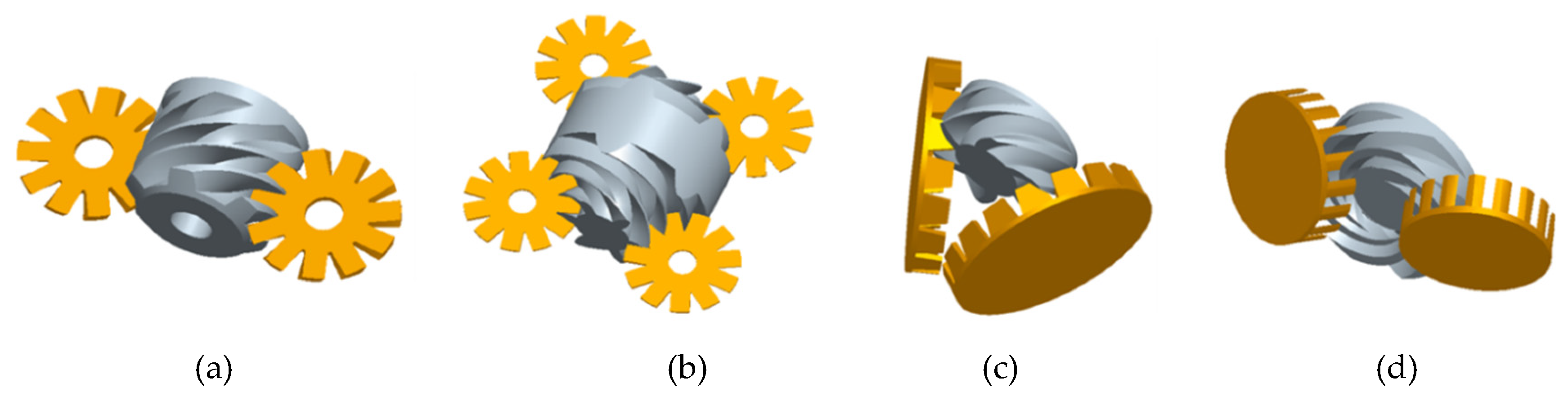
- Lei, B.; Wang, W.; Wu, Y.; Ma, C.; Wang, J.; Zhang, L.; Li, C.; Zhao, Y.; Zhi, R. Development and experimental study on a single screw expander integrated into an Organic Rankine Cycle. Energy 2016, 116, 43–52. [Google Scholar] [CrossRef]
- Wang, W.; Wu, Y.; Ma, C.; Liu, L.; Yu, J. Preliminary experimental study of single screw expander prototype. Appl. Therm. Eng. 2011, 31, 3684–3688. [Google Scholar] [CrossRef]
- Lu, Y.; He, W.; Wu, Y.; Ji, W.; Ma, C.; Guo, H. Performance study on compressed air refrigeration system based on single screw expander. Energy 2013, 55, 762–768. [Google Scholar] [CrossRef]
- Li, G.; Lei, B.; Wu, Y.; Zhi, R.; Zhao, Y.; Guo, Z.; Ma, C. Influence of inlet pressure and rotational speed on the performance of high pressure single screw expander prototype. Energy 2018, 147, 279–285. [Google Scholar] [CrossRef]
- Wang, W.; Wu, Y.; Ma, C.; Xia, G.; Wang, J. Experimental study on the performance of single screw expanders by gap adjustment. Energy 2013, 62, 379–384. [Google Scholar] [CrossRef]
- He, W.; Wu, Y.; Peng, Y.; Zhang, Y.; Ma, C.; Ma, G. Influence of intake pressure on the performance of single screw expander working with compressed air. Appl. Therm. Eng. 2013, 51, 662–669. [Google Scholar] [CrossRef]
- Wang, W.; Wu, Y.; Xia, G.; Ma, C.; Ji, W.; Zhang, Y. Experimental study on the performance of the single screw expander prototype by optimizing configuration. In Proceedings of the ASME 2012 6th International Conference on Energy Sustainability collocated with the ASME 2012 10th International Conference on Fuel Cell Science, Engineering and Technology, San Diego, CA, USA, 23–26 July 2012; American Society of Mechanical Engineers Digital Collection: New York, NY, USA, 2012; pp. 1281–1286. [Google Scholar]
- Xia, G.; Zhang, Y.; Wu, Y.; Ma, C.; Ji, W.; Liu, S.; Guo, H. Experimental study on the performance of single-screw expander with different inlet vapor dryness. Appl. Therm. Eng. 2015, 87, 34–40. [Google Scholar] [CrossRef]
- Zhang, Y.; Wu, Y.; Xia, G.; Ma, C.; Ji, W.; Liu, S.; Yang, F. Development and experimental study on organic Rankine cycle system with single-screw expander for waste heat recovery from exhaust of diesel engine. Energy 2014, 77, 499–508. [Google Scholar] [CrossRef]
- Zhang, X.; Zhang, Y.; Cao, M.; Wang, J.; Wu, Y.; Ma, C. Working Fluid Selection for Organic Rankine Cycle Using Single-Screw Expander. Energies 2019, 12, 3197. [Google Scholar] [CrossRef] [Green Version]
- Yan, J.L. Thermodynamic principles and formulas for choosing working fluids and parameters in designing power plant of low temperature heat. J. Eng. Thermophys. 1982, 3, 1–7. (In Chinese) [Google Scholar]
- He, C.; Liu, C.; Zhou, M. A new selection principle of working fluids for subcritical organic Rankine cycle coupling with different heat sources. Energy 2014, 68, 283–291. [Google Scholar] [CrossRef]
- ANSI/ASHRAE Standard 34-2016, Designation and Safety Classification of Refrigerants; ASHRAE: Atlanta, GA, USA, 2016.
- Intergovernmental Panel on Climate Change. In Climate Change 2007—The Physical Science Basis; Chapter 2: Changes in Atmospheric Constituents and in Radiative Forcing; Cambridge University Press: Cambridge, UK, 2007.
- Zhang, X.; Zhang, C.; He, M.; Wang, J. Selection and Evaluation of Dry and Isentropic Organic Working Fluids Used in Organic Rankine Cycle Based on the Turning Point on Their Saturated Vapor Curves. J. Therm. Sci. 2019, 28, 643–658. [Google Scholar] [CrossRef]
- Györke, G.; Deiters, U.K.; Groniewsky, A.; Lassu, I.; Imre, A.R. Novel Classification of Pure Working Fluids for Organic Rankine Cycle. Energy 2018, 145, 288–300. [Google Scholar] [CrossRef]
- Lemort, V.; Guillaume, L.; Legros, A.; Declayea, S.; Quoilin, S. A comparison of piston, screw and scroll expanders for small scale Rankine cycle systems. In Proceedings of the 3rd International Conference on Microgeneration and Related Technologies, Naples, Italy, 15–17 April 2013. [Google Scholar]
- Ziviani, D.; Gusev, S.; Lecompte, S.; Groll, E.A.; Braun, J.E.; Horton, W.T.; Broek, M.; De Paepe, M. Characterizing the performance of a single-screw expander in a small-scale organic Rankine cycle for waste heat recovery. Appl. Energy 2016, 181, 155–170. [Google Scholar] [CrossRef]


| Working Condition Parameter. | Value |
|---|---|
| Heat source temperature (°C) | 330–450 |
| Mass flow rate of flue gas (heat source) | 1700 |
| Inlet pressure of expander (MPa) | 1.6 |
| Inlet temperature of expander (°C) | 135 |
| Working fluid flow(kg/h) | 3100 |
| Type of evaporator | shell-and-tube heat exchanger |
| Evaporation temperature (°C) | 108–118 |
| Type of condenser | tube-in-tube heat exchanger |
| Condensation temperature (°C) | 30 |
| Cooling water temperature (°C) | 20 |
| Identifying Number | Components | Composition/Mass % | Safety Group [35] | Type |
|---|---|---|---|---|
| R401A | R22/R152a/R124 | 53/13/34 | A1 | wet |
| R401B | R22/R152a/R124 | 61/11/28 | A1 | wet |
| R401C | R22/R152a/R124 | 33/15/52 | A1 | wet |
| R402A | R125/propane/R22 | 60/2/38 | A1 | wet |
| R402B | R125/propane/R22 | 38/2/60 | A1 | wet |
| R403A | propane/R22/R218 | 5/75/20 | A2 | wet |
| R430B | propane/R22/R218 | 5/56/39 | A1 | wet |
| R404A | R125/R134a/R143a | 44/4/52 | A1 | wet |
| R405A | R22/R152a/R142b/RC318 | 45/7/5.5/42.5 | A1 | wet |
| R406A | R22/isobutane/R142b | 55/4/41 | A2 | wet |
| R407A | R32/R125/R134a | 20/40/40 | A1 | wet |
| R407B | R32/R125/R134a | 10/70/20 | A1 | wet |
| R407C | R32/R125/R134a | 23/25/52 | A1 | wet |
| R407D | R32/R125/R134a | 15/15/70 | A1 | wet |
| R407E | R32/R125/R134a | 25/15/60 | A1 | wet |
| R407F | R32/R125/R134a | 30/30/40 | A1 | wet |
| R408A | R125/R143a/R22 | 7/46/47 | A1 | wet |
| R409A | R22/R124/R142b | 60/25/15 | A1 | wet |
| R409B | R22/R124/R142b | 65/25/10 | A1 | wet |
| R410A | R32/R125 | 50/50 | A1 | wet |
| R410B | R32/R125 | 45/55 | A1 | wet |
| R411A | propylene/R22/R152a | 1.5/87.5/11 | A2 | wet |
| R411B | propylene/R22/R152a | 3/94/3 | A2 | wet |
| R412A | R22/R218/R142b | 70/5/25 | A2 | wet |
| R413A | R218/R134a/isobutane | 9/88/3 | A2 | wet |
| R414A | R22/R124/isobutane/R142b | 51/28.5/4/16.5 | A1 | wet |
| R414B | R22/R124/isobutane/R142b | 50/39/1.5/9.5 | A1 | wet |
| R415A | R22/R152a | 82/18 | A2 | wet |
| R415B | R22/R152a | 25/75 | A2 | wet |
| R416A | R134a/R124/butane | 59/39.5/1.5 | A1 | wet |
| R417A | R125/R134a/butane | 46.6/50/3.4 | A1 | wet |
| R418A | propane/R22/R152a | 1.5/96/2.5 | A2 | wet |
| R419A | R125/R134a/dimethylether | 77/19/4 | A2 | wet |
| R420A | R134a/R142b | 88/12 | A1 | wet |
| R421A | R125/R134a | 58/42 | A1 | wet |
| R421B | R125/R134a | 85/15 | A1 | wet |
| R422A | R125/R134a/isobutane | 85.1/11.5/3.4 | A1 | wet |
| R422B | R125/R134a/isobutane | 55/42/3 | A1 | wet |
| R422C | R125/R134a/isobutane | 82/15/3 | A1 | wet |
| R422D | R125/R134a/isobutane | 65.1/31.5/3.4 | A1 | wet |
| R423A | R134a/R227ea | 52.5/47.5 | A1 | isentropic |
| R424A | R125/R134a/isobutane/butane/ isopentane | 50.5/47/0.9/1/0.6 | A1 | wet |
| R425A | R32/R134a/R227ea | 18.5/69.5/12 | A1 | wet |
| R426A | R125/R134a/butane/isopentane | 5.1/93/1.3/0.6 | A1 | wet |
| R427A | R32/R125/R143a/R134a | 15/25/10/50 | A1 | wet |
| R428A | R125/R143a/propane/isobutane | 77.5/20/0.6/1.9 | A1 | wet |
| R429A | dimethylether/R152a/isobutane | 60/10/30 | A3 | wet |
| R430A | R152a/isobutane | 76/24 | A3 | wet |
| R431A | propane/R152a | 71/29 | A3 | wet |
| R432A | propylene/dimethylether | 80/20 | A3 | wet |
| R433A | propylene/propane | 30/70 | A3 | wet |
| R434A | R125/R143a/R134a/isobutane | 63.2/18/16/2.8 | A1 | wet |
| R435A | dimethylether/R152a | 80/20 | A3 | wet |
| R436A | propane/isobutane | 56/44 | A3 | isentropic |
| R436B | propane/isobutane | 52/48 | A3 | isentropic |
| R437A | R125/R134a/butane/pentane | 19.5/78.5/1.4/0.6 | A1 | wet |
| R438A | R32/R125/R134a/butane/ isopentane | 8.5/45/44.2/1.7/0.6 | A1 | wet |
| R441A | ethane/propane/isobutane/butane | 3.1/54.8/6/36.1 | A3 | wet |
| R442A | R32/R125/R134a/R152a/R227ea | 31/31/30/3/5 | A1 | wet |
| R443A | propylene/propane/isobutane | 55/40/5 | A3 | wet |
| R444A | R32/R152a/R1234ze(E) | 12/5/83 | A2L 1 | wet |
| Identifying Number | Critical Temperature (Tc)/K | The Extreme Temperature of Subcritical Region (0.9TC)/K | Components | Composition /Mass % | Safety Group | Type |
|---|---|---|---|---|---|---|
| R432A | 370.41 | 333.37 | propylene/ dimethylether | 80/20 | A3 | wet |
| R433A | 367.57 | 330.81 | propylene/ propane | 30/70 | A3 | wet |
| R436A | 389.04 | 350.14 | propane/ isobutane | 56/44 | A3 | isentropic |
| R436B | 390.58 | 351.52 | propane/ isobutane | 52/48 | A3 | isentropic |
| R441A | 391.62 | 352.46 | ethane/propane/ isobutane/butane | 3.1/54.8/6/36.1 | A3 | wet |
| R443A | 369.16 | 332.24 | propylene/propane /isobutane | 55/40/5 | A3 | wet |
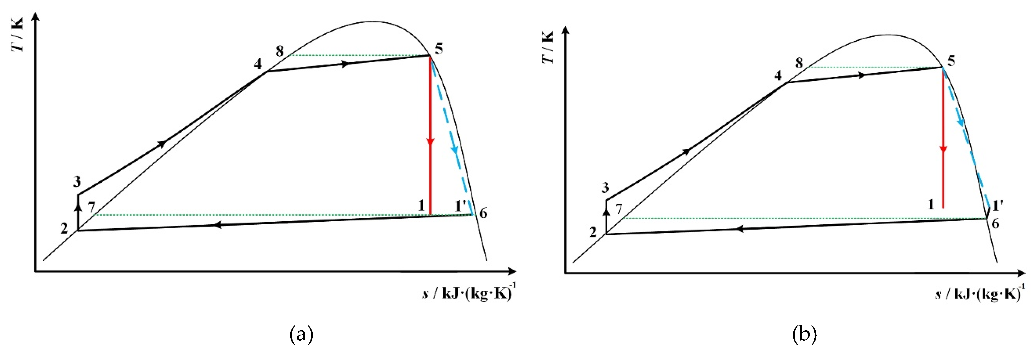
| State Point | Description | Determination |
|---|---|---|
| 1 | expander outlet | s1 = s5 |
| 2 | condenser outlet, at saturated liquid state | p2 = p1 |
| 3 | pump outlet | s3 = s2, p3 = p4 |
| 4 | at saturated liquid state | p4 = p5 |
| 5 | expander inlet | s5 = s1, T5 = 0.9Tc |
| 6 | at saturated vapor state | T6 = T1 for Figure 1 and Figure 5a, p6 = p1 for Figure 5b |
| 7 | at saturated liquid state | T7 = T6 |
| 8 | at saturated liquid state | T8 = T5 |
| Zeotropic Mixture | Expander Outlet Temperature T1/K | Net Work/kJ∙kg−1 | Thermal Efficiency/% | Heat Exchange Load of Condenser/kJ∙kg−1 | Temperature Glide in Evaporator/K | Temperature Glide in Condenser/K | Vapor Quality |
|---|---|---|---|---|---|---|---|
| R432A | 290 | 43.84 | 11.28 | 344.67 | 0.899 | 1.43 | 0.9450 |
| 295 | 37.94 | 10.10 | 337.84 | 1.37 | 0.9491 | ||
| 300 | 32.24 | 8.89 | 330.58 | 1.3 | 0.9534 | ||
| 305 | 26.82 | 7.67 | 322.86 | 1.24 | 0.9579 | ||
| 310 | 21.54 | 6.41 | 314.75 | 1.18 | 0.9628 | ||
| 315 | 16.54 | 5.13 | 306.15 | 1.12 | 0.9685 | ||
| 320 | 11.69 | 3.79 | 297.08 | 1.06 | 0.9749 | ||
| R433A | 290 | 40.11 | 10.66 | 336.24 | 0.263 | 0.32 | 0.9633 |
| 295 | 34.37 | 9.46 | 328.91 | 0.32 | 0.9661 | ||
| 300 | 28.89 | 8.25 | 321.13 | 0.31 | 0.9689 | ||
| 305 | 23.61 | 7.02 | 312.89 | 0.31 | 0.9720 | ||
| 310 | 18.55 | 5.75 | 304.16 | 0.3 | 0.9755 | ||
| 315 | 13.74 | 4.45 | 294.92 | 0.29 | 0.9794 | ||
| 320 | 9.13 | 3.10 | 285.13 | 0.28 | 0.9844 | ||
| R436A | 290 | 60.66 | 14.25 | 365.12 | 5.236 | 7.29 | 0.9973 |
| 295 | 54.40 | 13.17 | 358.79 | 7.17 | 0.9980 | ||
| 300 | 48.40 | 12.09 | 352.04 | 7.05 | 0.9985 | ||
| 305 | 42.59 | 10.99 | 344.87 | 6.92 | 0.9987 | ||
| 310 | 36.99 | 9.88 | 337.27 | 6.78 | 0.9987 | ||
| 315 | 31.60 | 8.76 | 329.23 | 6.62 | 0.9983 | ||
| 320 | 26.42 | 7.61 | 320.72 | 6.46 | 0.9979 | ||
| R436B | 290 | 62.39 | 14.58 | 365.65 | 5.342 | 7.48 | N/A |
| 295 | 56.15 | 13.51 | 359.37 | 7.37 | |||
| 300 | 50.17 | 12.45 | 352.72 | 7.28 | |||
| 305 | 44.34 | 11.37 | 345.61 | 7.14 | |||
| 310 | 38.70 | 10.27 | 338.02 | 6.96 | |||
| 315 | 33.35 | 9.18 | 330.01 | 6.8 | |||
| 320 | 28.17 | 8.05 | 321.58 | 6.64 | |||
| R441A | 290 | 69.38 | 14.68 | 403.38 | 12.958 | 18.54 | 0.9880 |
| 295 | 62.56 | 13.60 | 397.28 | 18.20 | 0.9895 | ||
| 300 | 55.94 | 12.52 | 390.79 | 17.85 | 0.9907 | ||
| 305 | 49.56 | 11.44 | 383.83 | 17.48 | 0.9916 | ||
| 310 | 43.40 | 10.34 | 376.44 | 17.09 | 0.9922 | ||
| 315 | 37.47 | 9.23 | 368.59 | 16.68 | 0.9928 | ||
| 320 | 31.75 | 8.10 | 360.25 | 16.26 | 0.9930 | ||
| R443A | 290 | 42.35 | 11.02 | 341.82 | 1.904 | 2.33 | 0.9580 |
| 295 | 36.50 | 9.83 | 334.78 | 2.3 | 0.9611 | ||
| 300 | 30.86 | 8.62 | 327.30 | 2.26 | 0.9644 | ||
| 305 | 25.47 | 7.39 | 319.35 | 2.21 | 0.9678 | ||
| 310 | 20.29 | 6.13 | 310.94 | 2.17 | 0.9717 | ||
| 315 | 15.35 | 4.84 | 302.01 | 2.11 | 0.9760 | ||
| 320 | 10.59 | 3.49 | 292.55 | 2.05 | 0.9812 |
| Rank | Net Work | Thermal Efficiency | Heat Exchange Load of Condenser | Temperature Glide in Evaporator | Temperature Glide in Condenser |
|---|---|---|---|---|---|
| R441A | R441A | R433A | R441A | R441A | R441A |
| R436B | R436B | R443A | R436B | R436B | R436B |
| R436A | R436A | R432A | R436A | R436A | R436A |
| R432A | R432A | R436A | R443A | R443A | R432A |
| R443A | R443A | R436B | R432A | R432A | R443A |
| R433A | R433A | R441A | R433A | R433A | R433A |
| State Point | Description | Determination |
|---|---|---|
| 1 | expander outlet without considering isentropic efficiency | s1 = s5 |
| 1’ | expander outlet considering isentropic efficiency | T1’= T1, p1’ = p6 |
| 2 | condenser outlet, at saturated liquid state | p2 = p6 |
| 3 | pump outlet | s3 = s2, p3 = p4 |
| 4 | at saturated liquid state | p4 = p5 |
| 5 | expander inlet | s5 = s1, T5 = 0.9Tc |
| 6 | At saturated vapor state | T6 = T1’ for Figure 5a, p6 = p1’ for Figure 8b and Figure 9a and Figure 9b |
| 7 | at saturated liquid state | T7 = T6 |
| 8 | at saturated liquid state | T8 = T5 |
| Zeotropic Mixture | Expander Outlet Temperature T1’/K | Net Work/kJ∙kg−1 | Thermal Efficiency/% | Heat Exchange Load of Condenser/kJ∙kg−1 | Temperature Glide in Evaporator/K | Temperature Glide in Condenser/K | Vapor Quality |
|---|---|---|---|---|---|---|---|
| R432A | 290 | 27.56 | 7.09 | 361.21 | 0.899 | 1.53 | 0.9903 |
| 295 | 23.77 | 6.32 | 352.21 | 1.45 | 0.9895 | ||
| 300 | 20.13 | 5.55 | 342.87 | 1.37 | 0.9888 | ||
| 305 | 16.68 | 4.77 | 333.12 | 1.29 | 0.9882 | ||
| 310 | 13.38 | 3.98 | 323.04 | 1.22 | 0.9881 | ||
| 315 | 10.20 | 3.16 | 312.55 | 1.15 | 0.9886 | ||
| 320 | 7.18 | 2.32 | 301.65 | 1.08 | 0.9899 | ||
| R433A | 290 | 25.07 | 6.55 | 357.54 | 0.263 | 0.34 | N/A |
| 295 | 21.46 | 5.85 | 345.36 | 0.33 | |||
| 300 | 18.00 | 5.12 | 333.46 | 0.32 | |||
| 305 | 14.65 | 4.35 | 321.85 | 0.31 | 0.9998 | ||
| 310 | 11.49 | 3.56 | 311.25 | 0.30 | 0.9983 | ||
| 315 | 8.45 | 2.74 | 300.21 | 0.29 | 0.9970 | ||
| 320 | 5.61 | 1.91 | 288.68 | 0.29 | 0.9967 | ||
| R436A | 290 | N/A | N/A | N/A | 5.236 | N/A | N/A |
| 295 | |||||||
| 300 | |||||||
| 305 | |||||||
| 310 | |||||||
| 315 | 19.31 | 4.81 | 382.36 | 7.07 | |||
| 320 | 16.09 | 4.27 | 360.47 | 6.81 | |||
| R436B | 290 | N/A | N/A | N/A | 5.342 | N/A | N/A |
| 295 | |||||||
| 300 | |||||||
| 305 | |||||||
| 310 | |||||||
| 315 | 20.37 | 4.97 | 389.67 | 7.31 | |||
| 320 | 17.17 | 4.48 | 366.15 | 7.03 | |||
| R441A | 290 | N/A | N/A | N/A | 12.958 | N/A | N/A |
| 295 | |||||||
| 300 | |||||||
| 305 | |||||||
| 310 | |||||||
| 315 | |||||||
| 320 | 19.52 | 4.57 | 407.94 | 17.42 | |||
| R443A | 290 | 26.55 | 6.84 | 361.71 | 1.904 | 2.57 | N/A |
| 295 | 22.85 | 6.12 | 350.27 | 2.50 | |||
| 300 | 19.28 | 5.38 | 339.33 | 2.42 | 0.9996 | ||
| 305 | 15.86 | 4.59 | 329.33 | 2.34 | 0.99784 | ||
| 310 | 12.58 | 3.79 | 318.93 | 2.27 | 0.9965 | ||
| 315 | 9.45 | 2.98 | 308.10 | 2.19 | 0.9956 | ||
| 320 | 6.51 | 2.15 | 296.79 | 2.11 | 0.9953 |
© 2020 by the authors. Licensee MDPI, Basel, Switzerland. This article is an open access article distributed under the terms and conditions of the Creative Commons Attribution (CC BY) license (http://creativecommons.org/licenses/by/4.0/).
Share and Cite
Zhang, X.; Zhang, Y.; Li, Z.; Wang, J.; Wu, Y.; Ma, C. Zeotropic Mixture Selection for an Organic Rankine Cycle Using a Single Screw Expander. Energies 2020, 13, 1022. https://doi.org/10.3390/en13051022
Zhang X, Zhang Y, Li Z, Wang J, Wu Y, Ma C. Zeotropic Mixture Selection for an Organic Rankine Cycle Using a Single Screw Expander. Energies. 2020; 13(5):1022. https://doi.org/10.3390/en13051022
Chicago/Turabian StyleZhang, Xinxin, Yin Zhang, Zhenlei Li, Jingfu Wang, Yuting Wu, and Chongfang Ma. 2020. "Zeotropic Mixture Selection for an Organic Rankine Cycle Using a Single Screw Expander" Energies 13, no. 5: 1022. https://doi.org/10.3390/en13051022