Review

A Review of Critical Stable Sectional Areas for the Surge Tanks of Hydropower Stations

School of Civil and Hydraulic Engineering, Huazhong University of Science and Technology, Wuhan 430074, China
*
Author to whom correspondence should be addressed.
Energies 2020, 13(23), 6466; https://doi.org/10.3390/en13236466
Submission received: 9 September 2020 / Revised: 8 November 2020 / Accepted: 5 December 2020 / Published: 7 December 2020
(This article belongs to the Section A: Sustainable Energy)

Abstract

:
The critical stable sectional area (CSSA) for surge tanks corresponds to the critical stable state of hydropower stations and is an important index to evaluate the stability of the turbine regulation system. The research on CSSA for surge tanks is always one of the most important topics in the area of transient processes of hydropower stations. The CSSA for surge tanks provides the value basis for the sectional area of surge tanks. In engineering practice, the CSSA for surge tanks is widely used to guide their hydraulic design. This paper provides a systematic literature review about the CSSA for surge tank of hydropower stations. Firstly, the CSSA for surge tanks based on hydraulic transients is discussed. Secondly, the CSSA for surge tanks based on hydraulic-mechanical-electrical coupling transients is presented. Thirdly, the CSSA for air cushion surge tanks is illustrated. Finally, the CSSA for combined surge tanks, i.e., upstream and downstream double surge tanks and upstream series double surge tanks, is presented. In future research, the CSSA for surge tanks of pumped storage power stations should be explored. The CSSA for surge tanks considering multi-energy complement is worth studying.

1. Introduction

A hydropower station is a complicated system that contains pipelines, turbine units and regulating systems [1,2]. During transient processes, the system variables change and the hydropower station enters a dynamic response process [3,4]. The dynamics of hydropower stations, including dynamic performance and stability, are influenced by different elements of the system [5]. The effect mechanism and strength of different elements on the dynamics of system are quite different. The fluid dynamics of pipelines are influenced by head losses, servo valves, controllers, etc [5]. The water hammer transient is dominated by a periodicity varying along the pressurized pipe, and the unsteady friction calculated by the Zielke model is distributed nonuniformly along the pipe [6]. Under different operating points of turbine, the output torque oscillations and pressure oscillations present different phenomena and laws [7]. The motion law of guide vanes also has a significant effect of the dynamics of hydropower stations. Based on the reasonable selection of a turbine shutdown scheme the amplitudes of the pressure pulsations in the vaneless spaces and runners can be obviously reduced [8]. The operation and control of hydropower station are realized by the control system, i.e., the turbine regulating system. By using a method of control system measurements, the dynamics of hydropower stations can be identified without extra excitation [9]. The rational design of a governor control strategy can effectively improve the dynamic performance and stability [10].
For the hydropower station, the pressure in the pipeline changes because of water hammer [11,12,13,14]. If the water hammer pressure is too great, the security of the hydropower station would be at stake [15,16]. In order to protect the pipeline and turbine unit, pressure reduction measures should be adopted.
There are two types of pressure reduction measures. The first type of pressure reduction measure is the governor regulation [17,18]. Specifically, the optimization of the closing law of the guide vanes is an effective measure for decreasing the water hammer pressure during large-amplitude disturbances [19,20,21]. The tuning of governor parameters is an effective measure for decreasing the pressure oscillation during small-amplitude disturbances [22]. The second type of pressure reduction measure is the pressure reduction facilities. The commonly used pressure reduction facilities include surge tanks [23,24] and sloping ceiling tailrace tunnels [25,26]. Surge tanks and sloping ceiling tailrace tunnels can reflect water hammer waves by using their shape features. The typical layout of a hydropower station with a surge tank is shown in Figure 1.
Between surge tanks and sloping ceiling tailrace tunnels, the former are the most widely used pressure reduction facilities found in hydropower stations [27,28]. A surge tank divides a hydropower station into two parts. The first part is the headrace tunnel. The second part is the penstock, turbine unit and regulation system. Surges tank should be set as close to the turbine unit as possible. Then the penstock flow inertia can be reduced and the turbine unit is protected. The body type, size and flow inertia of headrace tunnels determine the hydraulic parameters of surge tanks [29]. Because of the existence of surge tanks, the headrace tunnels and surge tanks form a connected subsystem. The headrace tunnels and turbine units are separated by the surge tanks and not connected directly. As a result, the influence of headrace tunnels on the turbine units is indirect. The setting of surge tanks has unfavorable effects on the safe and stable operation of hydropower stations. To be specific, the water flows back and forth in the subsystem of headrace tunnels and surge tanks, which brings about water level oscillations in surge tanks [30,31]. The water level oscillations in surge tank have non-minimum phase features. Moreover, the water level oscillation in surge tanks is a kind of mass wave and has a low frequency. For the turbine units, the water level oscillation in surge tanks represent a new external interference source. That external disturbance interacts with the frequency and power output of the turbine. Then the dynamic performance of the hydropower station is affected by the surge tank [32,33]. The complexity and requirements of dynamics of the turbine regulating system with surge tanks are higher than those of turbine regulating systems without surge tanks. The challenge for the control of turbine regulating system with surge tanks is huge [34].
Within the research area of transient processes of hydropower stations, two surge tank issues are the most important [35]. The first issue is the setting condition of surge tanks. The setting condition of surge tanks provides the judgment basis for the setting of a surge tank or not [36,37]. The second issue is the critical stable sectional area (CSSA) of surge tanks. The theme of this review is the CSSA for surge tanks.
The CSSA for surge tanks provides a value basis for the sectional area of surge tanks, which is the most important hydraulic parameter of surge tanks. The selection of the sectional area of surge tanks is related to the stability and economy for the design of hydropower stations with surge tanks. Those two issues are illuminated as follows:
(1)
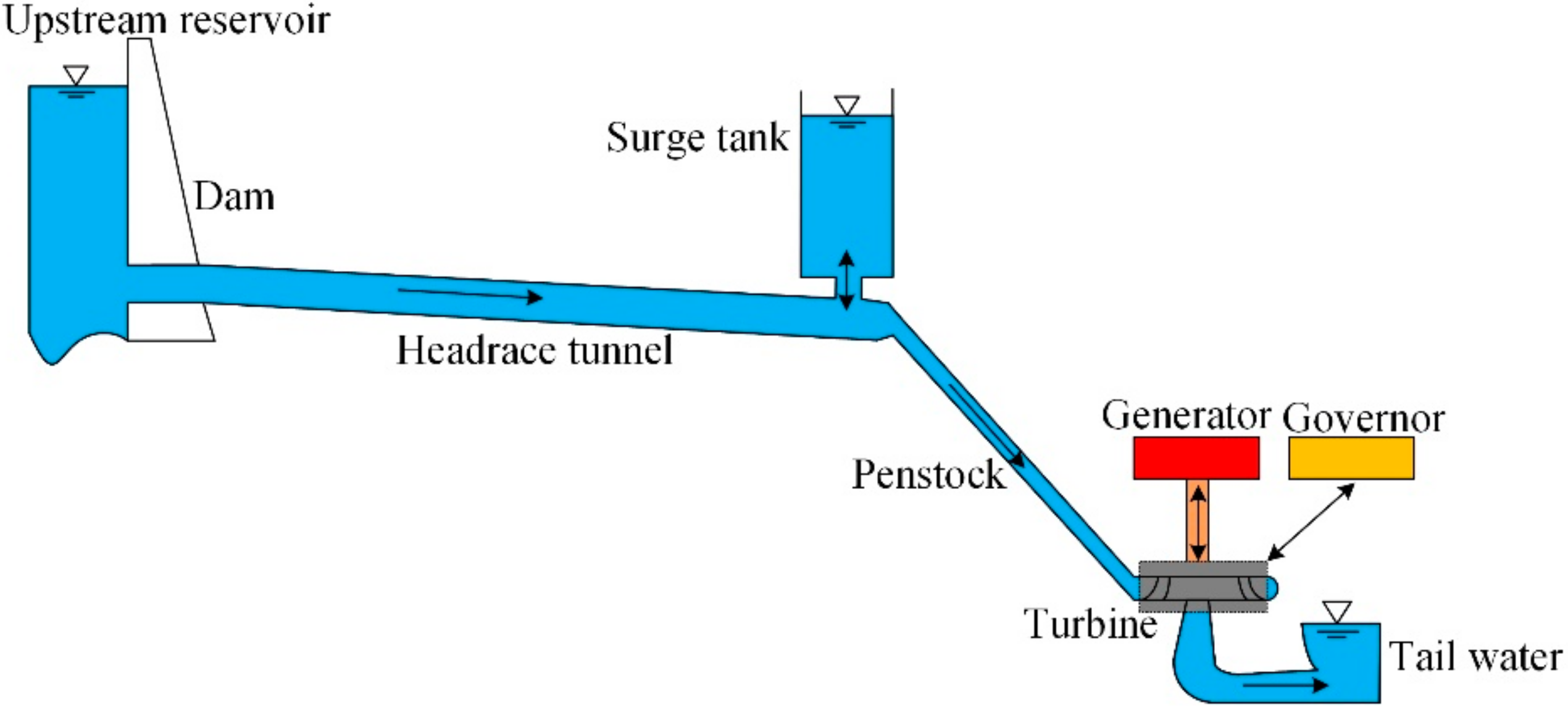
The stability for the design of surge tanks is a safety issue. The CSSA for surge tanks comes from the issue of stability of water level oscillations in surge tanks. For hydropower stations with surge tanks, the stability of the turbine regulating system is directly related to the sectional area of the surge tank [38]. The CSSA for surge tanks corresponds to the critical stable state of hydropower stations and is an important index to evaluate the stability of the turbine regulation system. In order to realize the stable operation of hydropower stations with surge tanks, the sectional area of surge tanks should be greater than the CSSA. If the sectional area of the surge tanks is less than the CSSA, the hydropower stations with surge tanks would be unstable. With the development of instability phenomena, the failure and destruction of the hydropower station may happen.
(2)
The economy in the design of surge tanks is an issue of investment and construction period. A greater surge tank sectional area can increase the stability of hydropower stations. However, with the increase of the sectional area of surge tanks, the investment and construction period of surge tanks increases. In engineering practice, the increase of investment and construction period is undesirable.
Therefore, issues of stability and economy coexist in the design of surge tanks and the requirements of stability and economy with respect to the sectional area of surge tanks are opposite. The selection of the sectional area of surge tanks should harmonize and balance the issues of stability and economy. The basis for the harmonization and balance of the issues of stability and economy is the CSSA for surge tanks. In engineering practice, the CSSA for surge tanks is widely used to guide their hydraulic design.
The research on CSSA for surge tanks is always one of the most important topics in the area of transient processes of hydropower stations. Over the past hundred-odd years, a lot of research projects were carried out and many achievements obtained. The motivation of the development for the studies on CSSA for surge tanks has two aspects. The first aspect is that the CSSA obtained for surge tanks can reflect and describe the physical phenomena and essence of surge tanks more realistically. In the early studies on CSSA for surge tanks, many simplifications and assumptions were made. The obtained CSSA for surge tanks had great errors. Then the efforts of studies on CSSA for surge tanks were focused on reducing these errors. The second aspect is that the obtained CSSA for surge tanks can harmonize and balance the issues of stability and economy more effectively. The stability is the primary condition for the design of surge tanks. Under the premise of stability, there is an inclination to reduce the sectional area of surge tanks. Then the efforts and attempts of studies on CSSA for surge tank are to reduce the sectional area of surges tank under the premise of stability. As a result, a safer and more economical design of surge tanks can be achieved.
Driven by the above two motivations, many research achievements of CSSA for surge tanks have been obtained. The research works proceed from the simple to the complex. In engineering practice, different types and layouts of surge tanks are widely used. Therefore, the research objects involve different types of surge tank, such as simple surge tank, throttling surge tank and air cushion surge tank. Combined surge tanks, i.e., upstream and downstream double surge tanks, and upstream series double surge tanks, are also studied. The most important outcome from the research achievements of CSSA for surge tanks is the CSSA analytic formula. The analytic formula of CSSA for surge tanks can clearly express the relationships among different components and easily reveal the influence of different parameters on CSSA. Moreover, in engineering practice, the analytic formula of CSSA for surge tanks can be easily understood and applied by practitioners to guide the hydraulic design of surge tanks.
This paper aims to systematically summarize the existing research achievements about the CSSA for surge tanks. The selected literatures are the representative achievements about the CSSA for surge tanks. The development history, process, and sequence of CSSA for surge tanks are illuminated. Different surge tank types and layouts are also discussed. It is expected that our review will refine and reveal the significance, practical value, new approaches, and future research trends of the topic of CSSA for surge tanks.
Based on the existing achievements of CSSA for hydropower station surge tanks, the review paper revolves around the following four aspects:
  • Aspect 1: CSSA for surge tanks based on hydraulic transients
  • Aspect 2: CSSA for surge tanks based on hydraulic-mechanical-electrical coupling transients
  • Aspect 3: CSSA for air cushion surge tanks
  • Aspect 4: CSSA for combined surge tanks
Aspects 1 and 2 focus on the simple surge tank and throttling surge tank, which are the most foundational and widely used types of surge tanks. The CSSAs for simple surge tanks and throttling surge tanks attract the most attention. The theoretical basis of the studies on CSSA for surge tanks undergoes the transformation from hydraulic transients to hydraulic-mechanical-electrical coupling transients. Aspect 3 focuses on one special, novel, and important surge tank type, i.e., air cushion surge tanks. Aspect 4 focuses another special and important surge tank layout, i.e., combined surge tanks. The above four aspects cover almost all the achievements of the field of CSSA for surge tanks.
The paper provides a systematic literature review of CSSA for surge tanks of hydropower station. In Section 2, the CSSA for surge tanks based on hydraulic transients is discussed. In Section 3, the CSSA for surge tanks based on hydraulic-mechanical-electrical coupling transients is presented. In Section 4, the CSSA for air cushion surge tanks is discussed. In Section 5, the CSSA for combined surge tanks is explained. In Section 6, the conclusions and future research trends are given.

2. CSSA for Surge Tanks Based on Hydraulic Transients

The water level oscillation in surge tanks is a typical dynamic response of the transient processes of hydropower stations. Basically, the water level oscillation stability of surge tanks is an issue of hydraulic transients. Originally, the study on CSSA for surge tanks was based on the hydraulic transients of headrace tunnels and surge tank systems. For CSSA for surge tanks based on hydraulic transients, the achievements are elaborated in this section.

2.1. CSSA for Surge Tanks Considering Hydraulic Transients

The concept of CSSA for surge tanks was firstly put forward by Thoma. The Thoma formula, i.e., Equation (1), is the first analytic formula of CSSA for surge tanks [39]. Equation (1) provides an analytic and convenient calculation method for the CSSA for surge tanks. More importantly, Equation (1) reveals the composition and influencing factors of CSSA for surge tanks. Equation (1) is a fractional equation and composed of H 0 and parameters of headrace tunnel and penstock. With the increase of L , f and h w m , and the decrease of H 0 and h w 0 , the value of CSSA for surge tanks becomes greater:
F t h = L f 2 α g H 0 h w 0 3 h w m
At present, the Thoma formula is the most widely used analytic formula of CSSA for surge tanks and is the recommended formula in design code [40]. In practical applications, the sectional area of surge tanks should be greater than the Thoma stable sectional area to realize the stability of water level oscillation in surge tanks.
The derivation of Thoma formula is based on the subsystem of headrace tunnels and surge tanks. The following assumptions are made [39]:
(1)
The amplitude of the water level oscillation in surge tanks is small.
(2)
The penstock is ignored.
(3)
The type of surge tank is a simple surge tank.
(4)
The governor should be extremely sensitive.
(5)
The efficiency and output of turbines remain unchanged.
(6)
The hydropower station is under isolated operating conditions.
The above assumptions can only approximately reflect the real operation situation of hydropower stations. Taking the above assumptions as breakthrough points, several improved formulas of CSSA for surge tanks are proposed.
Calame et al. [41] study the effect of penstock head loss on CSSA for surge tanks. It is indicated that the penstock head loss is not favorable for the stability of water level oscillations in surge tanks. In order to remedy the drawbacks caused by the assumptions, Jaeger [42] suggested a security factor, i.e., amplification factor, for the Thoma formula. That security factor is usually taken as 1.05–1.1.
In [43], Duggins investigated the stability of a simple surge tanks. The mathematical model is expressed in a non-dimensional form. A wider range of operating conditions of hydropower stations can be described by that model. The stability of water level oscillation in surge tanks under small disturbances is analyzed. In [44], Ruus studied the stability of oscillations in simple surge tanks. Two situations of water level oscillation in surge tanks, i.e., small oscillation and large oscillation, are compared. If the water level oscillation in a surge tank is undamped with a small amplitude at the rated head, it will become damped with a large amplitude.
Chaudhry et al. [45] analyzed the stability of water level oscillations in surge tanks by a phase plane method. Four cases, including constant power, constant gate opening, constant discharge and constant gate opening combined with constant power, are studied to evaluate the stability state of water level oscillations. In [46], Yang studied the stability of water level oscillations in surge tanks by using the Lyapunov stability theory. The Lyapunov function for water level oscillations is constructed and the stability criterion is broadened. By considering the throttling orifice head loss, the phase trajectory of water level oscillations in surge tanks is determined. The analysis results indicate that when the sectional area is less than the Thoma stable sectional area, the water level oscillations in simple surge tanks and throttling surge tanks are emanative and persistent, respectively.
In the Thoma assumptions, the amplitude of water level oscillations in surge tanks is small. The large amplitude stability of water level oscillations in surge tanks is also an important issue. For the issue of large amplitude stability, the key aspect is the treatment of the nonlinear terms in the mathematical model. It is difficult to deal with the issue of large amplitude stability by using analytical methods. Approximate solution methods are usually applied.
In [47,48], Marris studied the large amplitude stability of water level oscillations in simple surge tanks by a phase plane method. It is proved that the CSSA for surge tanks under large amplitude oscillations is greater than that under small amplitude oscillations. In [49], Li et al. analyzed the large amplitude water level oscillations in throttling surge tanks. For the water level oscillations in throttling surge tanks, a normalized model is derived and solved based on a numerical method. By using the phase plane method, the stability criterion is determined. The analysis results show that there may be two limit cycles around the singularity. For throttling surge tanks, the large amplitude water level oscillations may be stable when the sectional area is less than the Thoma stable sectional area.
In [50], Ji et al. studied the large amplitude stability of water level oscillations in surge tanks by using the Lyapunov stability theory. The analytic formula of CSSA for surge tanks under large amplitude is derived and shown in Equation (2). Equation (2) shows that the CSSA for surge tanks under large amplitude equals the multiplication of the Thoma stable sectional area and an amplification coefficient. The amplification coefficient is determined by the H 0 , Z 0 and Z * . With the increase of H 0 and decrease of Z 0 and Z * , the value of amplification coefficient becomes less. The analysis of Equation (2) indicates that the amplification coefficient is greater than 1. Therefore, the CSSA for surge tanks under large amplitude is greater than the Thoma stable sectional area. The stability requirement of large amplitude are higher than that of small amplitude:
F = 1 1 Z * H 0 Z 0 2 F t h

2.2. Effects of Hydraulic Factors on CSSA for Surge Tank

In [51], Ye et al. discussed the methods for reducing the CSSA for surge tanks. For the hydropower stations with several turbine units, a part of the turbine units can be regulated as the opening mode. During the transient process, if the guide vane opening of several turbine units remains unchanged, the stability of hydropower stations can be obviously improved. Then, the value of CSSA for surge tanks can be obviously decreased.
For the surge tanks with a connecting pipe or throttling orifice, the velocity head at the bottom of the surge tank is not completely lost. It is necessary to analyze the effect of velocity head on CSSA for surge tanks. In [52], Yang et al. studied the effects of velocity head and momentum term of connecting pipe on CSSA for downstream surge tanks. By considering the velocity head and momentum term of connecting pipes, the analytic formula of CSSA for downstream surge tanks is derived and shown in Equation (3). The analysis of Equation (3) indicates that the velocity head of connecting pipes is unfavorable for the stability of water level oscillations in downstream surge tanks, while the momentum term of connecting pipes is favorable for the stability of water level oscillations in downstream surge tanks. The effects of velocity head and momentum term can approximatively offset with each other. Then the value of Equation (3) is close to the Thoma stable sectional area, i.e., Equation (1). Based on the reasonable selection of the type and size of connecting pipe, the CSSA for downstream surge tanks can be further reduced:
F c s = L f H 0 g 2 α 1 2 g + σ ¯ 2 g
In [53], Vereide et al. studied the effect of surge tank throttling on governor stability in hydropower stations. A combined evaluation method for the effects of installing surge tanks throttles is proposed. Both numerical simulation and field measurement were carried out. Based on a case study, it is revealed that the throttle has an insignificant positive impact on governor stability. Power control is improved when a throttle is installed, and the throttle reduces the mass oscillations in the system.
In [54], Liu et al. investigated the influence of long connecting pipes and their shunt effect on CSSA for surge tanks. It is proved that the setting of long connecting pipes has no influence on CSSA for surge tanks. However, long connecting pipes are unfavorable for the attenuation of water level oscillations in surge tanks. The shunt effect of long connecting pipes can improve the stability of water level oscillations in surge tanks and reduce the CSSA.
Based on the Thoma assumptions, Zhao et al. [55] studied the CSSA for downstream surge tanks of hydropower stations with complicated tailrace systems. The analysis results indicated that, with the increase of turbine head or the decrease of tailrace tunnel length, the CSSA for downstream surge tanks decreases. In [56], Li et al. studied the CSSA for downstream surge tanks of hydropower stations with free surface-pressurized flow tailrace tunnels. The Thoma assumptions are adopted and the water level oscillation in tailrace tunnels is considered. Then the analytic formula of CSSA for downstream surge tanks is derived and shown in Equation (4). The correctness and accuracy of Equation (4) are verified based on a numerical simulation of a project case. The form of Equation (4) is similar to that of Equation (1). The difference between Equation (4) and Equation (1) is the denominator. In Equation (4), the denominator has one more term, i.e., 3 Q 0 B c cos θ . That term is introduced by the free surface-pressurized flow tailrace tunnel and can increase the value of F c s . Moreover, with the decrease of θ and increase of B and c , the value of F c s becomes less. Therefore, the free surface-pressurized flow tailrace tunnel can worsen the stability of hydropower stations:
F c s = L w f 2 β g H 0 h w 0 3 h w m 3 Q 0 B c cos θ
In [57], Zhu et al. studied the CSSA for surge tanks considering nonlinearity of head loss of headrace tunnel and steady output of turbine. The formulas for the CSSA for surge tanks are derived (Table 1). The correctness and accuracy of different CSSAs are verified (Figure 2). F t h 1 is the Thoma stable sectional area, i.e., Equation (1). F t h 2 , F t h 3 and F t h 4 equal the multiplication of Thoma stable sectional area and amplification coefficients. The amplification coefficients reflect the influence of the nonlinearity of head loss of headrace tunnels and steady output of turbine on CSSA for surge tanks. The effect of the nonlinearity of head loss of headrace tunnels on CSSA for surge tanks is much more significant than that of the nonlinearity of the steady output of turbines. The formula for CSSA for surge tanks considering both the nonlinearity of head loss of headrace tunnels and nonlinearity of steady output of turbines has a higher precision than the Thoma formula. Note that for MM-1, both the nonlinearity of head loss of headrace tunnels and steady output of turbines are not considered. For MM-2, only the nonlinearity of head loss of headrace tunnels is considered. For MM-3, only the steady output of turbines is considered. For MM-4, both the nonlinearity of head loss of headrace tunnels and steady turbine output are considered.

3. CSSA for Surge Tanks Based on Hydraulic-Mechanical-Electrical Coupling Transients

A hydropower station is a hydraulic-mechanical-electrical coupling system. Specifically, the hydraulic system contains headrace tunnels, surge tanks and penstocks. The mechanical system contains turbines and governors. The electrical system contains generators and power grids. During transient processes, the dynamic response of hydropower stations is affected by the hydraulic system, mechanical system and electrical system. The stability of hydropower stations is determined by the dynamic characteristics of the hydraulic system, mechanical system and electrical system.
Surge tanks connect the headrace tunnel and penstock. The penstock connects the surge tank and mechanical system. The turbine and generator are the core components of the hydropower unit. The water level oscillations in surge tanks are a representative dynamic responses of hydropower stations during transient processes. The CSSA for surge tanks is affected by the hydraulic system, mechanical system and electrical system. Therefore, the rigorous and complete study on the CSSA for surge tanks should be based on the hydraulic-mechanical-electrical coupling transient processes of hydropower stations. The influencing factors should be introduced into the analytic formula of CSSA for surge tanks.
The achievements for CSSA for surge tanks based on hydraulic-mechanical-electrical coupling transients, are elaborated in this section.

3.1. Effects of Governor and Turbine on CSSA for Surge Tanks

In the Thoma assumptions, the power output of turbines is regarded as a constant. In that situation, the governor should be extremely sensitive. In practice, the governor cannot maintain the turbine output as a constant without transient processes. The governor regulation always needs a certain period. Therefore, the CSSA for surge tanks is affected by the governor.
Krivehenko [58] held that the governor has an obvious effect on CSSA for surge tanks. By the rational selection of governor parameters, a hydropower station can become stable when the sectional area of its surge tank is smaller than the Thoma stable sectional area.
In [59], Shen analyzed the effect of governor parameters on CSSA for surge tanks. A mathematical model containing the pipeline system, hydropower unit and governor is established. By using the state matrix method, the stability conditions of hydropower stations are determined. Then the stable domains of hydropower stations under different values of en are drawn. The results indicate that the effects of bt, Td and en on the stability of hydropower stations are obvious ehen the values of bt and Td are small, the CSSA for surge tanks is close to the Thoma stable sectional area. With the increase of Td, the CSSA for surge tanks decreases. When the values of bt and Td are sufficiently large, the hydropower station can become stable if the sectional area of its surge tank is smaller than the Thoma stable sectional area.
In the Thoma assumptions, the efficiency of the turbine is regarded as unchanged. In fact, the efficiency of turbine always changes as the operating condition point changes. Under different operating condition points, the discharge characteristic and torque characteristic are different. Therefore, the CSSA for surge tanks is affected by the turbine.
Borel [60] studied the effect of turbine efficiency on the CSSA for surge tanks. The investigation indicates that the turbine efficiency has an obvious effect on the CSSA for surge tanks. If the change of turbine efficiency is consistent with the change of power output of turbine, the CSSA for surge tanks can be decreased. On the contrary, the CSSA for surge tanks should increase to maintain the stability of water level oscillations.
In [61], Yang et al. investigated the influence of turbine characteristics on the CSSA for surge tanks. The turbine characteristics are expressed by six transfer coefficients. By considering the turbine characteristics, the CSSA for surge tanks is derived and shown in Equation (5). Equation (5) indicates that the CSSA F equals the product of Thoma stable sectional area and comprehensive transfer coefficient of the turbine e. The influence of turbine characteristics on the CSSA for surge tanks is caused by the change of turbine efficiency. The value of e may be greater or less than 1. Therefore, F may be greater or less than F t h . Based on the physical meaning of e, the change law of value of e under different regions of characteristic curves of turbines is determined. The analysis shows that the maximum CSSA for surge tanks depends on the rated head, not the minimum head:
F = e F t h
In [62], Yang et al. studied the CSSA for downstream surge tank considering the turbine characteristics. Based on the linear model of hydropower stations and transfer function theory, the analytic formula of CSSA for downstream surge tanks considering turbine characteristics is derived and shown in Equation (6). The form of Equation (6) is similar to that of Equation (1). The difference between Equations (6) and Equation (1) is the denominator. The coefficient of turbine characteristics δ is introduced into the denominator. The terms of turbine characteristics in Equation (6) can be estimated based on experience. The comparison with Thoma stable sectional area indicates that Equation (6) has a higher accuracy. The value of CSSA for downstream surge tanks derived from Equation (6) is greater than that from Equation (1). Therefore, the turbine characteristics can worsen the stability of hydropower stations. The consideration of turbine characteristics makes the CSSA for downstream surge tanks closer to the true value:
F t h = L f 2 α g H 0 δ h w 0 δ 2 + 1 δ h w m

3.2. Hydraulic-Mechanical-Electrical Coupling CSSA for Surge Tanks

In [63], Dong studied the CSSA for surge tanks based on hydraulic-mechanical-electrical coupling transient of hydropower stations. A linear mathematical model containing hydraulic system, mechanical system and electrical system is established. The integration transfer function of the dynamic system is derived. Based on the Hurwitz criterion and numerical simulation, the stability condition about the sectional area of surge tanks is determined. Then, a complete analytic formula of CSSA for surge tanks is derived from the stability condition. That formula contains the parameters of governor and turbine. However, the effects of governor and turbine on CSSA for surge tanks are not revealed adequately. In [64], Shou analyzed the characteristics of different subsystems of hydropower stations, including governors, turbines, generators, pipelines and surge tanks. The analysis results show that the hydraulic damping, turbine characteristics and governor parameters have an obvious effect on shape of frequency characteristic of the whole hydropower system. Because of that influence, the value of CSSA for surge tanks can be changed by hydraulic damping, turbine characteristics and governor parameters.
In [65], Guo et al. studied the CSSA for surge tanks considering the penstock and governor. It is proved that the criterion of CSSA for surge tanks is determined by the coefficient of first order derivative term of the system oscillation equation. Based on the expression for the coefficient of first order derivative term, the analytic formula of CSSA for surge tanks is derived and shown in Equation (7). Equation (7) shows that the CSSA for surge tanks is composed of three terms, i.e., term of headrace tunnel F t h 1 , term of penstock F t h 2 and term of governor F t h 3 . The term of headrace tunnel F t h 1 is the Thoma stable sectional area. The turbine characteristics are also included in F t h 2 and F t h 3 . F t h 2 is always greater than zero, while F t h 3 is always less than zero. The effect of penstock on CSSA for surge tanks is positive feedback and can increase the value of CSSA. With the increase of L t and f t , both F t h 2 and F t h become greater. The effect of governor on CSSA for surge tanks is negative feedback and can decrease the value of CSSA. With the increase of b t and T d , both F t h 3 and F t h become less:
F t h = F t h 1 + F t h 2 + F t h 3
where:
F t h 1 = e L y f y 2 α y g H 0 2 e h t 0 , F t h 2 = e L t f t 2 α t g H 0 2 e h t 0 , F t h 3 = H 0 + 2 e q h h y 0 + h t 0 1 + b t e g e x e y H 0 + 2 b t e g e x e q h + e h e q x e y e h t 0 + 2 e h e y b t e q x e q y h y 0 H 0 H 0 2 e h t 0 H 0 + 2 e q h h t 0 Q y 0 2 h y 0 T d .
In [66], Ma et al. investigated the stability of water level oscillations in surge tanks under the grid-connected operation of hydropower stations. The power output of turbine is assumed as a constant. A part of the output variation caused by water level oscillations in surge tanks is undertaken by the power grid. The analysis results indicate that, under the grid-connected operation conditions, the CSSA for surge tanks is smaller than the Thoma stable sectional area. The CSSA for surge tank under grid-connected operation depends on the proportion of capacity of hydropower station in the power grid. In [67], He et al. study the CSSA for surge tanks considering characteristics of the power grid. The value of CSSA for surge tanks becomes smaller when the scale of the power grid increases.
In [68], Guo et al. studied the operation stability of hydropower systems with surge tanks under grid-connected operation conditions. A linear model containing the power grid is established. By analyzing the stability conditions of the hydropower system, an analytic formula of CSSA for surge tanks considering the power grid is derived and shown in Equation (8). Equation (8) is a complete hydraulic-mechanical-electrical coupling CSSA for surge tank. F t h P 1 , F t h P 2 , F t h P 3 and F t h P 4 are the terms of the headrace tunnel, penstock, governor and power grid, respectively. F t h P 1 is the Thoma stable sectional area. The headrace tunnel term F t h P 1 and penstock term F t h P 2 can increase the CSSA for surge tanks. The governor term F t h P 3 and power grid term F t h P 4 can decrease the CSSA for surge tanks. With the increase of the scale of power grid, the favorable effect of the power grid on the system stability becomes greater and the CSSA for surge tanks decreases:
F t h P = F t h P 1 + F t h P 2 + F t h P 3 + F t h P 4
where:
F t h P 1 = e 0 f y L y 2 α y g ( H 0 2 e 0 h t 0 ) ,   F t h P 2 = e 0 f t L t 2 α t g ( H 0 2 e 0 h t 0 ) , F t h P 3 = ( e n b t e y + 0.5 ) H 0 + ( e n e 1 b t e y e 0 ) ( h t 0 + h y 0 ) Q 0 T d h y 0 ( H 0 2 e 0 h t 0 ) ,   F t h P 4 = e * Q 0 h y 0 ( H 0 2 e 0 h t 0 )
In order to reduce the sectional area of the surge tank, the water pressure of pipelines is introduced into the turbine regulating system as a part of the input signal [69]. By considering the water pressure feedback, a model of a turbine regulation system is established. The frequency-domain characteristics of the turbine regulation system are analyzed based on the inverse frequency characteristic method. The analysis results show that the introduction of water pressure feedback can decrease the value of CSSA for surge tanks. In [70], Wang et al. studied the effect of connecting pipes on CSSA for surge tanks. If the connecting pipes of surge tanks are long, the flow inertia of the connecting pipes is great. Based on theoretical derivation, numerical calculation, and project case, it is proved that the flow inertia of connecting pipes is favorable for the stability of water level oscillations in surge tanks.
In [71], Wang et al. investigated the influence of tailrace channels on the stability of hydropower stations with downstream surge tanks. By considering the water level oscillations in tailrace channels, the space state equation of the turbine regulation system of hydropower stations is established. Then the stable domain of the turbine regulation system is drawn and the influence of tailrace channels on stability is analyzed. The results indicate that considering water level oscillations in tailrace channels is favorable for the stability of turbine regulating systems and can reduce the value of CSSA for downstream surge tanks.
In [72], Guo et al. studied the hydraulic-mechanical-electrical coupling CSSA for surge tanks under the operating conditions of primary frequency regulation. The obtained analytic formulas of CSSA for surge tanks under primary frequency regulation are shown in Equations (9) and (10). The CSSA for surge tanks under primary frequency regulation makes the system reach the critical stable state, and is an important basis for the design of surge tanks. Taking a hydropower station as an example, the values of F P F R 1 and F P F R 2 are calculated from Equations (9) and (10) and shown in Figure 3. For the value, distribution and change law, there is a great difference between F P F R 1 and F P F R 2 . Equations (9) and (10) contain the parameters of e p and K i . In practical applications for primary frequency regulation, the CSSA for surge tanks and governor parameters can be tuned and optimized together based on Equations (9) and (10):
F P F R 1 = l 1 + l 1 2 4 l 0 l 2 2 l 0
F P F R 2 = l 1 l 1 2 4 l 0 l 2 2 l 0
In [73], Peng et al. studied the saturation characteristics for stability of turbine regulating systems with surge tanks. The concept of the saturation critical sectional area of surge tanks is proposed. Detailed calculation procedures are put forward. Based on the calculation procedures and a project case, the saturation critical sectional area of surge tanks Fs is determined and compared with the Thoma stable sectional area. The result is shown in Figure 4.
When the sectional area of the surge tank is greater than the saturation critical sectional area, the stability of a hydropower station cannot become better anymore with the increase of sectional area of the surge tank.

4. CSSA for Air Cushion Surge Tank

Air cushion surge tanks are a special type of surge tank. In the air cushion surge tank, the top is closed. The interspace between the tank top and water surface is filled with compressed air. The water level and surge oscillation in the tank are constrained by this compressed air. Air cushion surge tanks are especially suitable for the following situations [74]:
(1)
The hydropower station has a high head, a small discharge, and a long headrace tunnel.
(2)
Along the pipeline, the geological conditions are good, but the mountain near the powerhouse is low.
(3)
For the hydropower station project area, the environmental protection requirements are stringent.
Because of the existence and effect of compressed air, the dynamic behaviors of water level and surge oscillation in air cushion surge tanks are obviously different with those in open surge tanks. For air cushion surge tank, the achievements of CSSA are elaborated in this section.
In [75], Chaudhry et al. analyzed the stability of water level oscillations in air cushion surge tanks by using the phase plane method. Firstly the basic equations are established. Then, based on the phase plane method, the singularities of the system are determined and the stability criteria are derived. By using the isoclines method, the phase curves are drawn (Figure 5). The effect of air polytropic index on the amplitude of water level oscillations is analyzed. The analysis results indicate that if the guide vane opening limitation is considered, the attenuation rate of water level oscillations in air cushion surge tanks becomes greater.
In [76], Peng et al. proposed a special air cushion surge tank layout, i.e., series double air cushion surge tanks, to reduce the sectional area of single surge tanks. The differential equation for the water level oscillations in series double air cushion surge tanks is established. The stability conditions of water level oscillations are derived. The analysis results indicate that the obtained stability conditions are the generalization of the Thoma condition. Based on a practical calculation example, the influence of factors on stability of water level oscillations are analyzed. It is proved that the local head loss and locations of surge tanks have a significant effect on the stable domain and CSSAs of surge tanks.
In [77,78], Yang et al. studied the small-amplitude oscillation and large-amplitude oscillation in air cushion surge tanks from the view of system dynamics. Firstly, the stability of small-amplitude oscillations in air cushion surge tanks with throttling was analyzed. The nonlinear stability analysis shows that the turbine regulation system with air cushion surge tanks shows a Hopf bifurcation with the sectional area of the surge tank as controlling factor. Before the bifurcation, an unstable limit cycle occurs and determines the asymptotic stability domain. After the bifurcation, there may be two limit cycles. Then, the large-amplitude oscillation in air cushion surge tanks is analyzed. The stability diagram specifies domains of asymptotic stability on the phase plane. The stability diagram shows that the sectional area of surge tanks under the critical stable state of large amplitude surge is greater than that of small amplitude surge.
In [79,80], Guo et al. investigated the dynamic behaviors of turbine regulation systems with air cushion surge tanks based on both linear and nonlinear complete mathematical models. The linear stability of turbine regulating systems with air cushion surge tanks is analyzed based on transfer function theory. The Thoma assumptions are broken through. By using stable domain, the effects of system parameters, regulation modes of the governor on stability are illuminated (Figure 6). Based on direct numerical integration and Hopf bifurcation theory, the nonlinear dynamic response of turbine regulation systems is described and analyzed (Figure 7).
In [81], Svee derived the analytic formula of CSSA for air cushion surge tanks for the first time. The analytic formula is shown in Equation (11):
F s v = F t h 1 + m P 0 l 0 = L f 2 g α + 1 2 g H 0 h w 0 3 h w m 1 + m P 0 l 0
Equation (11) is the most widely used analytic formula of CSSA for air cushion surge tanks. As an analytic and concise formula, Equation (11) provides a succinct and effective method for the determination of CSSA for air cushion surge tanks. Moreover, Equation (11) reveals the relationship between the CSSA for air cushion surge tank F s v and CSSA for open surge tank F t h . Those two CSSAs have a proportional relationship, and the proportional coefficient depends on the parameters of air cushion surge tanks, i.e., m , P 0 and l 0 . With the decrease of l 0 and increase of m and P 0 , the proportional coefficient becomes greater. Under normal conditions, the proportional coefficient is much greater than 1. Therefore, F s v is much greater than F t h .
After the appearance of Equation (11), more and more improved formulas of CSSA for air cushion surge tanks have been proposed and studied. In [82], Wang investigated the CSSA for downstream air cushion surge tanks of hydropower stations with complicated tailrace pipeline systems. In the research object, there are several tailrace tunnels. The tailrace tunnels are in parallel with each other and share one downstream air cushion surge tank. The analytic formula of CSSA for downstream air cushion surge tanks is derived and generalized.
In [83], Ji et al. proposed an improved formula of CSSA for air cushion surge tanks. Compared with the mathematical model in [81], the velocity head at the bottom of the surge tank and throttling orifice head loss are considered. Then a second-order differential equation of the water level oscillation is obtained. Based on the stability theory of a second-order dynamic system, an improved formula of CSSA for air cushion surge tanks, i.e., Equation (12), is derived. Equation (11) is a special case of Equation (12) when the velocity head at the bottom of the surge tank and throttling orifice head loss are not considered. The coefficient of velocity head at the bottom of the surge tank α and head loss coefficient of the throttling orifice head loss ζ are introduced into the denominator of Equation (12). Therefore, the velocity head at the bottom of surge tanks and throttling orifice head loss are favorable for the damping of water level oscillations and can reduce the value of CSSA for air cushion surge tanks. With the increase of α and ζ , the value of CSSA for air cushion surge tank becomes less:
F s v J = F s v α α + α + ζ = L f 2 g α + 1 2 g H 0 h w 0 3 h w m 1 + m P 0 l 0 α α + α + ζ
In [84,85,86], a classical nonlinear theory, i.e. Lyapunov stability theory, is applied for the study of the CSSA for air cushion surge tanks. Zhang et al. [84] considered the case that the inflow throttling orifice head loss is not equal to the outflow throttling orifice head loss. The nonlinear differential equation of water level oscillations in air cushion surge tanks is obtained from basic equations. Based on Lyapunov stability theory, the stability of water level oscillations is analyzed and a formula of CSSA for air cushion surge tanks is derived. The comparative analysis indicates that the value of CSSA for air cushion surge tanks in [84] is smaller than that in [81]. Ma et al. [85] studied the stability of large-amplitude oscillations in air cushion surge tanks by using the Lyapunov stability theory. For the large-amplitude oscillation, the analytic formula of CSSA for air cushion surge tanks is derived. The analysis of the obtained analytic formula shows that Equation (11) is a special case of the analytic formula described in [85]. With the increase of the amplitude of water level oscillations, the value of CSSA for air cushion surge tanks becomes greater. However, the value of CSSA for air cushion surge tanks under small-amplitude oscillations is close to that under large-amplitude oscillations. Zhang et al. [86] unified the analytic formulas of CSSA for air cushion surge tanks under both small-amplitude oscillation and large-amplitude oscillation conditions. According to the Lyapunov stability theory and wave theory, an analytic formula of CSSA for air cushion surge tanks which is suitable for both small-amplitude oscillations and large-amplitude oscillations is derived.
In [87], Zhang et al. derived the CSSA for air cushion surge tanks according to the experimental value of throttling orifice head loss. Based on the model test of air cushion surge tanks, the throttling orifice head loss is analyzed. By combining the model test and theoretical analysis, the analytic formula of CSSA for air cushion surge tanks is derived. The obtained formula can reflect the effect of throttling orifice head loss on the value of CSSA for air cushion surge tanks. Based on the obtained formula, the value of CSSA for air cushion surge tanks can be reduced by tuning the throttling orifice head loss reasonably.
In [88], Li et al. studied the CSSA for air cushion surge tanks by using the hydraulic-mechanical-electrical coupling hydropower stations. The stability of the turbine regulating system with air cushion surge tanks is analyzed. Then the analytic formula of CSSA for air cushion surge tanks considering the effect of penstock and governor, i.e., Equation (13), is derived. For the CSSA for air cushion surge tanks, the Thoma assumptions are broken through. Equation (13) shows that the CSSA for air cushion surge tank is composed of three terms, i.e., term of headrace tunnel F t h 1 1 + m P 0 l 0 , term of penstock F t h 2 1 + m P 0 l 0 , and term of governor F t h 3 1 + m P 0 l 0 . The term of headrace tunnel F t h 1 1 + m P 0 l 0 equates to Equation (11). The term of penstock F t h 2 1 + m P 0 l 0 is always greater than zero, while the term of governor F t h 3 1 + m P 0 l 0 is always less than zero. The effect of penstock on CSSA for air cushion surge tanks is positive feedback and can increase the value of CSSA. The effect of governor on CSSA for air cushion surge tanks is negative feedback and can decrease the value of CSSA. The analysis of Equation (13) indicates that the maximum CSSA for air cushion surge tanks depends on one head which lies between the rated head and maximum head:
F s v = F t h 1 + F t h 2 + F t h 3 1 + m P 0 l 0
where:
F t h 1 = e L y f y 2 α y g H 0 2 e h t 0 ,   F t h 2 = e L t f t 2 α t g H 0 2 e h t 0 , F t h 3 = 1 e 2 h y 0 + h t 0 H 0 + e g e x e y + e q h e g e x + e q x e h e y 2 h y 0 + h t 0 H 0 b t Q 0 H 0 T d 2 h t 0 H 0 2 e h t 0
In [89], Zhang et al. discussed the parameter values for the calculation of CSSA for air cushion surge tanks. It is pointed out that the head, discharge, and thermodynamic process of air are the key influencing parameters for the calculation of CSSA for air cushion surge tanks. During the practical engineering analysis, the thermodynamic process of air in surge tanks should be regarded as an isothermal change process. The turbine head should be selected as the maximum head. The turbine discharge should be selected as the discharge corresponding to the maximum head.

5. CSSA for Combined Surge Tanks

Combined surge tanks are a kind of special layout mode for surge tanks of hydropower stations. When both the headrace tunnel and tailrace tunnel of a hydropower station are long, both an upstream surge tank and a downstream surge tank must be set. That kind of combined surge tanks are the upstream and downstream double surge tanks and is shown in Figure 8a. When the headrace tunnel of a hydropower station is super long, one surge tank on the headrace tunnel cannot guarantee the safety of the hydropower station. Setting two surge tanks on one headrace tunnel is a method to solve that problem. That kind of combined surge tanks is the upstream series double surge tanks and is shown in Figure 8b.
For the combined surge tanks, the interaction effect between surge tanks makes the water level oscillations in the surge tanks extremely complicated. As a result, the stability and CSSA for combined surge tanks are much more complex than those of single surge tanks. For upstream and downstream double surge tanks and upstream series double surge tanks, the achievements of CSSA are elaborated in this section.

5.1. Upstream and Downstream Double Surge Tanks

In [90], Suo studied the stability of the turbine regulation systems of hydropower stations with upstream and downstream double surge tanks under small load disturbance conditions. By considering the pipeline system, turbine, generator and governor, the differential equations that describe the dynamic performance of the hydropower station are derived. The coefficients matrix of the differential equations is determined. Based on numerical simulation, the characteristic values of coefficients matrix are calculated. From the characteristic values, the stability of the turbine regulation system of a hydropower station with upstream and downstream double surge tanks is judged. According to the change rule of characteristic values, the effect of the sectional areas of upstream and downstream double surge tanks on the stability of the turbine regulatingon system is analyzed.
In [91], Yang et al. analyzed the stability of water level oscillations in upstream and downstream double surge tanks in detail. Under the assumption of ideal regulation, the differential equation for the water level oscillations in upstream and downstream double surge tanks is derived. The stability criterion of water level oscillations is determined. The stable domain of the hydropower station is drawn. The change law of stable domain is analyzed. According to stable domain and stability criterion, the analytical formulas for the interference point and resonance point of stable domain are derived (Equations (14) and (15)). n 1 max F t h 1 and n 2 max F t h 2 are the recommended values of the upstream surge tank and downstream surge tank, respectively. Under n 1 max F t h 1 and n 2 max F t h 2 , the hydropower station with upstream and downstream double surge tanks is stable. Equations (14) and (15) show that n 1 max F t h 1 and n 2 max F t h 2 are greater than the resonance sectional areas of the upstream surge tank and downstream surge tank, respectively. Design criteria and a computing method of values of CSSA for upstream and downstream double surge tanks are proposed. Based on an engineering project, the proposed method is applied and verified:
n 1 max = n 1 r 1 r 2
n 2 max = n 2 r 1 r 1
In [92], Song studied the nonlinear stability of water level oscillations in upstream and downstream double surge tanks. Based on the theory of system dynamics, the discrimination formula for the stability of water level oscillations is derived. For the water level oscillations in upstream and downstream double surge tanks, the accuracy of nonlinear stability is higher than that of linear stability. In [93], Geng et al. simulated the water level oscillations in upstream and downstream double surge tanks by using the method of characteristics. The simulation results show that the periods of water level oscillations in upstream and downstream double surge tanks are close to the theoretical periods.
In [94], Lai et al. analyzed the influence of the governor on the stability of hydropower stations with upstream and downstream double surge tanks. Based on a linear model that includes pipeline system, turbine and governor, the stable domain of the hydropower station is determined. Then the effect of governor parameters on the stable domain is analyzed. The analysis indicates that the stable domain becomes larger when the effect of the governor is considered. The governor is favorable for the stability of hydropower stations with upstream and downstream double surge tanks.
In [95], Chen et al. established the complete linear mathematical models of turbine regulating system of hydropower stations with upstream and downstream double surge tanks under both the frequency regulation mode and power regulation mode. The stable domains of the turbine regulation system under frequency regulation mode and power regulation mode are drawn and compared (Figure 9). The comparison shows that the stability of turbine regulation systems under frequency regulation mode is obviously worse than that under power regulation mode. In [96], Chen et al. studied the bifurcation characteristics of a turbine regulating system with saturation nonlinearity. The stable domains of turbine regulation system considering nonlinear controller or linear controller are compared (Figure 10). For the hydropower stations with upstream and downstream double surge tanks, the saturation nonlinearity of controllers is unfavorable for the stability of turbine regulating systems.

5.2. Upstream Series Double Surge Tanks

In [97], Teng et al. analyzed the stable state of turbine regulating systems with upstream series double surge tanks. Under the assumptions of small disturbance, rigid water hammer and linearization, the mathematical model of turbine regulating systems with upstream series double surge tanks is established. Based on the automatic control theory, the transfer function and linear motion equation of the turbine regulation system are derived. The stable domain is drawn to quantitatively describe the stability of turbine regulating systems. By using the stable domain, the influence of sectional areas for the main surge tank and auxiliary surge tank on stability is analyzed. The values of CSSA for upstream series double surge tanks are investigated. To improve the stability of turbine regulation systems, the optimal combination of sectional areas for a main surge tank and an auxiliary surge tank is determined.
In [98], Chen et al. investigated the values of CSSA for upstream series double surge tanks. According to the Thoma assumptions, the characteristic equation of a hydropower station with upstream series double surge tanks is derived. The stable domain of CSSA for upstream series double surge tanks is determined. When the sectional areas for upstream series double surge tanks change, the change rule of stable domain is analyzed. At the intersection point, the value of CSSA for the main surge tank is the smallest. The stable domain and intersection point provide a foundation for selection of sectional areas for upstream series double surge tanks.
In [99], Li et al. studied the stable state of hydropower stations with upstream series double surge tanks. The analysis is based on the numerical simulation by using transient flow theory and the method of characteristics. According to an engineering example, the influence of factors of upstream series double surge tanks on stability is studied. The results indicate that the effect of sectional area for the main surge tank on the stability of a hydropower station is more significant than that of the auxiliary surge tank.

6. Conclusions

This paper provides a systematic literature review about the CSSA for surge tanks of hydropower stations. Firstly, the CSSA for surge tanks based on hydraulic transients is discussed. Secondly, the CSSA for surge tanks based on hydraulic-mechanical-electrical coupling transients is stated. Thirdly, the CSSA for air cushion surge tanks is illuminated. Finally, the CSSA for combined surge tanks, i.e., upstream and downstream double surge tanks, and upstream series double surge tanks, is presented. The conclusions of the review paper are as follows:
(1)
The concept of CSSA for surge tanks was firstly put forward by Thoma. The Thoma formula is the first analytic formula of CSSA for surge tanks. The head loss of penstocks is not favorable for the stability of water level oscillations in surge tanks. If the water level oscillations in surge tanks are undamped with a small amplitude at the rated head, it will become damped with a large amplitude. The CSSA for surge tanks under large amplitude oscillation conditions is greater than that under small amplitude oscillation conditions. The velocity head of connecting pipes is unfavorable for the stability of water level oscillations in downstream surge tanks. The shunt effect of long connecting pipes can improve the stability of water level oscillations in surge tanks and reduce the CSSA for surge tanks. With the increase of turbine head or the decrease of tailrace tunnel length, the CSSA for downstream surge tanks decreases.
(2)
The governor and turbine efficiency have an obvious effect on CSSA for surge tanks. The maximum CSSA for surge tanks depends on the rated head, not the minimum head. The criterion of CSSA for surge tanks is determined by the coefficient of first order derivative term of the system oscillation equation. The introduction of water pressure feedback can decrease the value of CSSA for surge tanks. The consideration of flow inertia of connecting pipes can reduce the value of CSSA for surge tanks. The consideration of water level oscillations in tailrace channels is favorable for the stability of turbine regulating systems and can reduce the value of CSSA for surge tanks.
(3)
If the guide vane opening limitation is considered, the attenuation rate of water level oscillations in air cushion surge tanks becomes greater. The local head loss and locations of surge tanks have a significant effect on the CSSAs of surge tanks. The sectional area of surge tanks under the critical stable state of large amplitude surge is greater than that of small amplitude surge. The CSSA for air cushion surge tanks and CSSA for open surge tanks have a proportional relationship. The maximum CSSA for air cushion surge tanks depends on one head which lies between the rated head and maximum head.
(4)
For the water level oscillations in upstream and downstream double surge tanks, the accuracy of nonlinear stability is higher than that of linear stability. For hydropower stations with upstream and downstream double surge tanks, the saturation nonlinearity of the controller is unfavorable for the stability of the turbine regulation system. The influence of the sectional area of the main surge tank on the stability of hydropower stations is more significant than that of auxiliary surge tanks.
(5)
New approaches about the research and engineering application of CSSA for surge tank can be refined as follows:
(a)
Regarding the research approaches of CSSA for surge tanks, the analytical method is dominant and the most widely used. The analytical methods gradually transform from linear methods to nonlinear methods. The linear methods include the transfer function method, Hurwitz criterion method, and inverse frequency characteristic method. The nonlinear methods include the phase plane method, Hopf bifurcation method, and Lyapunov stability method. With the development of hydropower stations, surge tanks research objects have become more and more complicated. The adopted research approaches should reflect and describe the physical essence of water level oscillations. Advanced nonlinear methods, combined linear and nonlinear methods, and combined nonlinear and nonlinear methods are the potential new research approaches.
(b)
Regarding the engineering application of CSSA for surge tanks, a new approach for the hydraulic design of surge tanks can be obtained. In the past, the sectional area of surge tanks was designed by considering the influence of headrace tunnels. In the latest analytic formulas of CSSA for surge tanks, the parameters of headrace tunnel, penstock, turbine, generator, and governor are included. The sectional area of surge tanks can be designed and optimized together with the parameters of headrace tunnel, penstock, turbine, generator and governor. That design approach is a new approach for the design of hydropower stations. Because more influencing factors are considered simultaneously, a more reasonable design result of sectional area of surge tanks can be obtained.
Some future research trends about the CSSA for surge tanks of hydropower stations can be pointed out as follows.
(1)
With the further development of hydropower, more and more pumped storage power stations are being constructed. The pipeline layout and characteristics of turbines of pumped storage power stations are obviously different with those of conventional hydropower stations. The CSSA for surge tanks of conventional hydropower stations cannot be simply adopted for pumped storage power stations. The existing achievements about CSSA for surge tanks are mainly based on conventional hydropower stations, hence, the CSSA for surge tanks of pumped storage power stations should be explored.
(2)
Hydropower stations play an important regulation role in modern power systems. In modern power systems, there are other types of power sources, such as thermal power, wind power and photovoltaic power. The operation and control of multi-energy complementary energy sources are complicated and have a significant effect on hydropower stations. The CSSA for surge tanks considering multi-energy complement is worth studying.

Author Contributions

Conceptualization, W.G. and Y.L.; methodology, F.Q.; software, X.X.; validation, W.G., Y.L. and X.X.; formal analysis, F.Q.; investigation, W.G.; resources, W.G.; data curation, Y.L.; writing—original draft preparation, W.G. and Y.L.; writing—review and editing, W.G.; visualization, Y.L.; supervision, W.G.; project administration, W.G.; funding acquisition, W.G. All authors have read and agreed to the published version of the manuscript.

Funding

This work was supported by the National Natural Science Foundation of China (Project No. 51909097).

Conflicts of Interest

The authors declare no conflict of interest.

Nomenclature

BWidth of sloping ceiling tailrace tunnel, m
btTemporary droop
cWave velocity of free surface flow section, m/s
e, e’, e0, e*Comprehensive transfer coefficient of turbine
egLoad self-regulation coefficient
eh, ex, eyMoment transfer coefficients of turbine
enStatic frequency self-regulation coefficient of grid load
ep, bpDroop of speed
eqh, eqx, eqyDischarge transfer coefficients of turbine
FSectional area of surge tank, m2
f, fySectional area of headrace tunnel, m2
FcsCSSA for downstream surge tank, m2
FPFRCSSA for surge tank under primary frequency regulation, m2
FsSaturation critical sectional area for surge tank, m2
FsvCSSA for air cushion surge tank, m2
ftSectional area of penstock, m2
FthCSSA for surge tank, m2
gAcceleration of gravity, m/s2
H0Turbine net head, m
HgTurbine gross head, m
hw0, hy0, hf0Head loss of headrace tunnel, m
hwm, ht0Head loss of penstock, m
KiIntegral gain, s−1
KpProportional gain
L, Lw, LyLength of headrace tunnel, m
l0Height of air chamber, m
LtLength of penstock, m
mGas polytropic exponent
n1, n2Coefficients of proportionality
nfAmplification coefficient of sectional area of surge tank
P0Absolute air pressure in surge tank, m
Q0, Qy0Discharge in headrace tunnel, m3/s
qPRelative turbine discharge
qyEEquilibrium point of relative discharge in headrace tunnel
tTime, s
TdDamping device time constant, s
Vy0Flow velocity in headrace tunnel, m/s
xRelative turbine frequency
yRelative guide vane opening
ZWater level in surge tank, m
Z*Amplitude peak in the first period of water level oscillation in surge tank, m
Z0Initial water level in surge tank, m
zEEquilibrium point of relative water level in surge tank
α, αyHead loss coefficient of headrace tunnel, s2/m
α’Coefficient of velocity head at the bottom of surge tank, s2/m
αtHead loss coefficient of penstock, s2/m
αTDischarge coefficient of head loss of throttling orifice head loss, s2/m5
βCoefficient of head loss of sloping ceiling tailrace tunnel, s2/m
δCoefficient of turbine characteristics
ζHead loss coefficient of throttling orifice head loss, s2/m
θCeiling slope angle of sloping ceiling tailrace tunnel, rad
σ ¯ Coefficient of momentum term of connecting pipe

References

  1. Kishor, N.; Fraile-Ardanuy, J. Modeling and Dynamic Behaviour of Hydropower Plants; The Institution of Engineering and Technology: Stevenage, UK, 2017. [Google Scholar]
  2. Guo, W.C.; Yang, J.D.; Teng, Y. Surge wave characteristics for hydropower station with upstream series double surge tanks in load rejection transient. Renew. Energy 2017, 108, 488–501. [Google Scholar] [CrossRef]
  3. Chaudhry, M.H. Applied Hydraulic Transients; Springer: New York, NY, USA, 2014. [Google Scholar]
  4. Guo, W.C.; Zhu, D.Y. A review of the transient process and control for a hydropower station with a super long headrace tunnel. Energies 2018, 11, 2994. [Google Scholar] [CrossRef] [Green Version]
  5. Viersma, T.J. Analysis, Synthesis and Design of Hydraulic Servosystems and Pipelines; Elsevier Science Publishers: Amsterdam, The Netherlands, 1980. [Google Scholar]
  6. Storli, P.T.; Nielsen, T.K. Transient friction in pressurized pipes. I: Investigation of Zielke’s model. J. Hydraul. Eng. 2011, 137, 577–584. [Google Scholar] [CrossRef]
  7. Trivedi, C.; Cervantes, M.J.; Gandhi, B.K.; Dahlhaug, O.G. Experimental and numerical studies for a high head Francis turbine at several operating points. J. Fluids Eng. 2013, 135, 111102. [Google Scholar] [CrossRef]
  8. Trivedi, C.; Gandhi, B.K.; Cervantes, M.J.; Dahlhaug, O.G. Experimental investigations of a model Francis turbine during shutdown at synchronous speed. Renew. Energy 2015, 83, 828–836. [Google Scholar] [CrossRef]
  9. Jakobsen, S.H.; Bombois, X.; Uhlen, K. Non-intrusive identification of hydro power plants’ dynamics using control system measurements. Int. J. Electr. Power 2020, 122, 106180. [Google Scholar] [CrossRef]
  10. Walter, J.G.G.; Garces, A.; Fosso, O.B. Passivity-based control for small hydro-power generation with PMSG and VSC. IEEE Access 2020, 8, 153001–153010. [Google Scholar]
  11. Wang, S.Q.; Yu, X.D.; Ni, W.X.; Zhang, J. Water hammer protection combined with air vessel and surge tanks in long-distance water supply project. J. Drain. Irrig. Mach. Engine 2019, 37, 406–412. [Google Scholar]
  12. Bai, M.M.; Wang, F.J.; Lei, C.; Wang, L.; Liu, B.C. Effect of bypass valve on hydraulic transient process in long water transport pipelines with graveity flow. J. Drain. Irrig. Mach. Engine 2019, 37, 58–62. [Google Scholar]
  13. Chu, S.P.; Zhang, J.; Yu, X.D. Influence of tee minor hydraulic loss model on draft tube inlet pressure and upsurge in surge chamber. J. Drain. Irrig. Mach. Engine 2018, 36, 42–49. [Google Scholar]
  14. Kim, S. Design of surge tank for water supply systems using the impulse response method with the GA algorithm. J. Mech. Sci. Technol. 2010, 24, 629–636. [Google Scholar] [CrossRef]
  15. Wang, B.B.; Guo, W.C.; Yang, J.D. Analytical solutions for determining extreme water levels in surge tank of hydropower station under combined operating conditions. Commun. Nonlinear Sci. 2017, 47, 394–406. [Google Scholar] [CrossRef]
  16. Guo, W.C.; Wang, B.B.; Yang, J.D.; Xue, Y.L. Optimal control of water level oscillations in surge tank of hydropower station with long headrace tunnel under combined operating conditions. Appl. Math. Modell. 2017, 47, 260–275. [Google Scholar] [CrossRef]
  17. Wei, S.P. Hydraulic Turbine Regulation; Huazhong University of Science and Technology Press: Wuhan, China, 2009. [Google Scholar]
  18. Qu, F.L.; Guo, W.C. Robust H control for hydro-turbine governing system of hydropower plant with super long headrace tunnel. Int. J. Electr. Power 2021, 124, 106336. [Google Scholar] [CrossRef]
  19. Zhou, T.C.; Zhang, J.; Yu, X.D.; Chu, S.P. Optimizing closure law of wicket gates in hydraulic turbine based on simulated annealing. J. Drain. Irrig. Mach. Engine 2018, 36, 320–326. [Google Scholar]
  20. Zhou, D.Q.; Jiang, S.W.; Chen, H.X. Numerical simulation of start-up process of mixed flow pump unit combined with hydraulic control butterfly valve action. J. Drain. Irrig. Mach. Engine 2019, 37, 112–117. [Google Scholar]
  21. Chu, S.P.; Zhang, J.; Chen, S.; Yu, X.D. Influence of closure law of wicket gate on successive load rejection condition. J. Drain. Irrig. Mach. Engine 2019, 37, 31–37. [Google Scholar]
  22. Guo, W.C.; Yang, J.D.; Yang, W.J.; Chen, J.P.; Teng, Y. Regulation quality for frequency response of turbine regulating system of isolated hydroelectric power plant with surge tank. Int. J. Electr. Power 2015, 73, 528–538. [Google Scholar] [CrossRef] [Green Version]
  23. Mosonyi, E.; Seth, H.B. The surge tank—A device for controlling water hammer. Water Power Dam Constr. 1975, 27, 69–74. [Google Scholar]
  24. Johnson, R.D. The surge tank in water power plants. Trans. ASME 1908, 30, 443–474. [Google Scholar]
  25. Guo, W.C.; Yang, J.D.; Wang, M.J.; Lai, X. Nonlinear modeling and stability analysis of hydro-turbine governing system with sloping ceiling tailrace tunnel under load disturbance. Energy Convers. Manag. 2015, 106, 127–138. [Google Scholar] [CrossRef]
  26. Guo, W.C.; Yang, J.D.; Chen, J.P.; Wang, M.J. Nonlinear modeling and dynamic control of hydro-turbine governing system with upstream surge tank and sloping ceiling tailrace tunnel. Nonlinear Dynam. 2016, 84, 1383–1397. [Google Scholar] [CrossRef]
  27. Jaeger, C. Present trends in surge tank design. Proc. Inst. Mech. Eng. 1954, 168, 91–124. [Google Scholar] [CrossRef]
  28. Vereide, K.; Richter, W.; Zenz, G.; Lia, L. Surge tank research in Austria and Norway. Wasserwirtschaft 2015, 105, 58–62. [Google Scholar] [CrossRef] [Green Version]
  29. Liu, Q.Z.; Peng, S.Z. Surge Tank of Hydropower Station; China Waterpower Press: Beijing, China, 1995. [Google Scholar]
  30. Guo, W.C.; Yang, J.D. Modeling and dynamic response control for primary frequency regulation of hydro-turbine governing system with surge tank. Renew. Energy 2018, 121, 173–187. [Google Scholar] [CrossRef]
  31. Guo, W.C.; Yang, J.D. Combined effect of upstream surge chamber and sloping ceiling tailrace tunnel on dynamic performance of turbine regulating system of hydroelectric power plant. Chaos Soliton Fract. 2017, 99, 243–255. [Google Scholar] [CrossRef]
  32. Xu, X.Y.; Guo, W.C. Stability of speed regulating system of hydropower station with surge tank considering nonlinear turbine characteristics. Renew. Energy 2020, 162, 960–972. [Google Scholar] [CrossRef]
  33. Guo, W.C.; Peng, Z.Y. Order reduction and dynamic performance of hydropower system with surge tank for grid-connected operation. Sustain. Energy Technol. Assess. 2020, 40, 100777. [Google Scholar]
  34. Walter, J.G.G.; Garces, A.; Fosso, O.B.; Andrés, E.M. Passivity-based control of power systems considering hydro-turbine with surge tank. IEEE Trans. Power Syst. 2020, 35, 2002–2011. [Google Scholar]
  35. Wu, R.Q.; Chen, J.Z. Hydraulic Transients of Hydropower Station; China Water Power Press: Beijing, China, 1997. [Google Scholar]
  36. Guo, W.C.; Zhu, D.Y. Setting condition of downstream surge tank of hydropower station with sloping ceiling tailrace tunnel. Chaos Soliton Fract. 2020, 134, 109698. [Google Scholar] [CrossRef]
  37. Zhu, D.Y.; Guo, W.C. Setting condition of surge tank based on stability of hydro-turbine governing system considering nonlinear penstock head loss. Int. J. Electr. Power 2019, 113, 372–382. [Google Scholar] [CrossRef]
  38. Guo, W.C.; Yang, J.D. Dynamic performance analysis of hydro-turbine governing system considering combined effect of downstream surge tank and sloping ceiling tailrace tunnel. Renew. Energy 2018, 129, 638–651. [Google Scholar] [CrossRef]
  39. Jaeger, C. A review of surge-tank stability criteria. J. Basic Eng. 1960, 82, 765–775. [Google Scholar] [CrossRef]
  40. National Energy Administration of China. Design Code for Surge Chamber of Hydropower Stations; NB/T 35021–2014; China Electric Power Press: Beijing, China, 2014. [Google Scholar]
  41. Calame, J.; Gaden, D. Theorie Des Chambers d’ Equilibre; Gantur-Villars: Paris, France, 1926. [Google Scholar]
  42. Jaeger, C. Contribution to the stability theory of systems of surge tanks. Trans. ASME 1958, 80, 1574–1584. [Google Scholar]
  43. Duggins, R.K. The stability of a simple surge tank. J. Basic Eng. 1968, 90, 97. [Google Scholar] [CrossRef]
  44. Ruus, E. Stability of oscillations in simple surge tank. J. Hydraul. Div. 1969, 95, 1577–1588. [Google Scholar]
  45. Chaudhry, M.H.; Ruus, E. Surge tank stability by phase plane method. J. Hydraul. Div. 1971, 97, 489–503. [Google Scholar]
  46. Yang, L.X. The extending application of Lyapunov′s stability theory in the subject of water level oscillating stability in the surge tank. J. Hydraul. Eng. 1999, 9, 34–39. [Google Scholar]
  47. Marris, A.W. Large water-level displacements in the simple surge tank. J. Basic Eng. 1959, 81, 446–454. [Google Scholar] [CrossRef]
  48. Marris, A.W. The phase-plane topology of the simple surge-tank equation. J. Basic Eng. 1961, 83, 700–708. [Google Scholar] [CrossRef]
  49. Li, X.X.; Brekke, H. Large amplitude water level oscillations in throttled surge tanks. J. Hydraul. Res. 1989, 27, 537–551. [Google Scholar] [CrossRef]
  50. Ji, K.; Ma, Y.X.; Wang, S.Q. Study on the stable sectional area of surge tank under large fluctuation process. J. Hydraul. Eng. 1990, 5, 45–51. [Google Scholar]
  51. Ye, F.Y.; Wang, S.R. Discussion on measures to reduce stable Section of surge tank. Water Resour. Hydropower Eng. 1990, 8, 36–40. [Google Scholar]
  52. Yang, J.D.; Lai, X.; Chen, J.Z. The influence of connecting pipe velocity head and momentum term on the stable area of surge tank. J. Hydraul. Eng. 1995, 7, 59–65. [Google Scholar]
  53. Vereide, K.; Svingen, B.; Nielsen, T.K.; Lia, L. The effect of surge tank throttling on governor stability, power control, and hydraulic transients in hydropower plants. IEEE Trans. Energy Convers. 2017, 32, 91–98. [Google Scholar] [CrossRef] [Green Version]
  54. Liu, C.; Cheng, Y.G. Stability and attenuation of surge wave in surge chamber with long lateral pipe and distributary. Water Resources Power 2012, 2, 131–135. [Google Scholar]
  55. Zhao, G.L.; Yang, J.D.; Li, J.P. Stable sectional area of tailrace surge tank on complicated tailrace system. J. Yangtze River Sci. Res. Inst. 2004, 21, 3–5. [Google Scholar]
  56. Li, L.; Yang, J.D.; Liu, M.Q. Stable sectional area of tailrace surge tank on tailrace system with free surface-pressurized flow. J. Huazhong Univ. Sci. Technol. 2015, 43, 38–41. [Google Scholar]
  57. Zhu, D.Y.; Guo, W.C. Critical sectional area of surge chamber considering nonlinearity of head loss of diversion tunnel and steady output of turbine. Chaos Soliton Fract. 2019, 127, 165–172. [Google Scholar] [CrossRef]
  58. Krivehenko, G.N. Transition Process in Power Plant of Hydropower Station; China Water Power Press: Beijing, China, 1981. [Google Scholar]
  59. Shen, Z.Y. The influence of governor parameters on critical stable section of surge tank. J. Hydraul. Eng. 1986, 5, 69–74. [Google Scholar]
  60. Borel, M. Essai de systematisation de L’étude réglage d’un groupe hydro-électrique. Journées de l’hydraulique 1959, 5, 105–111. [Google Scholar]
  61. Yang, J.D.; Lai, X.; Chen, J.Z. The effect turbine characteristic on stable sectional area of surge tank. J. Hydraul. Eng. 1998, 2, 7–11. [Google Scholar]
  62. Yang, F.; Li, L.M.; Li, G.H. Research on the critical stable cross-sectional area of the tailrace surge chamber considering the hydraulic turbine characteristics. China Rural Water Hydropower 2017, 11, 199–203. [Google Scholar]
  63. Dong, X.L. Research on the stable cross-section area of surge tank of hydropower station. J. Hydraul. Eng. 1980, 4, 37–48. [Google Scholar]
  64. Shou, M.H. Study on the hydraulic turbine regulation with surge tank. Water Resour. Hydropower Eng. 1991, 7, 28–34. [Google Scholar]
  65. Guo, W.C.; Yang, J.D.; Chen, Y.M.; Shan, X.J. Study on critical stable sectional area of surge chamber considering penstock fluid inertia and governor characteristics. J. Hydroelectr. Eng. 2014, 33, 171–178. [Google Scholar]
  66. Ma, Y.X.; Ma, Q.Z.; Ji, K. Investigation on stable cross section of large oscillation surge chamber in electric system. J. Hydraul. Eng. 1998, 29, 63–68. [Google Scholar]
  67. He, Z.F.; Peng, Z.Y.; Gui, S.B. Research on critical stable section of surge tank considering power network characteristics. Express Water Resour. Hydropower Inf. 2019, 40, 56–61. [Google Scholar]
  68. Guo, W.C.; Peng, Z.Y. Hydropower system operation stability considering the coupling effect of water potential energy in surge tank and power grid. Renew. Energy 2019, 134, 846–861. [Google Scholar] [CrossRef]
  69. Liu, J.H.; Liu, C.Y. Introducing water pressure feedback to reduce the stable section of the surge tank. Water Resour. Power 1990, 8, 232–241. [Google Scholar]
  70. Wang, C.; Yang, J.D. Influence of the length of the connecting pipe on the stable area of the surge chamber and the quality of small fluctuation adjustment. J. Hydraul. Eng. 2015, 34, 93–98. [Google Scholar]
  71. Wang, M.J.; Yang, J.D.; Wang, H. Stability analysis of small fluctuation regulation of tailrace system containing open channel. J. Hydraul. Eng. 2015, 34, 161–168. [Google Scholar]
  72. Guo, W.C.; Yang, J.D. Stability performance for primary frequency regulation of hydro-turbine governing system with surge tank. Appl. Math. Modell. 2018, 54, 446–466. [Google Scholar] [CrossRef]
  73. Peng, Z.Y.; Guo, W.C. Saturation characteristics for stability of hydro-turbine governing system with surge tank. Renew. Energy 2019, 131, 318–332. [Google Scholar] [CrossRef]
  74. National Energy Administration of China. Design Code for Air Cushion Surge Chamber of Hydropower Stations; NB/T 35080–2016; China Waterpower Press: Beijing, China, 2016. [Google Scholar]
  75. Chaudhry, M.H.; Sabbah, M.A.; Fowler, J.E. Analysis and stability of closed surge tanks. J. Hydraul. Eng. 1985, 111, 1079–1096. [Google Scholar] [CrossRef]
  76. Peng, S.Z. The Stable conditions and transition process of small fluctuations in pneumatic surge tank system of hydropower station. J. Hydraul. Eng. 1986, 2, 34–53. [Google Scholar]
  77. Yang, X.L.; Chen, S.K. Stability of air-cushion surge tanks with throttling. J. Hydraul. Res. 1992, 30, 835–850. [Google Scholar] [CrossRef]
  78. Yang, X.L.; Cederwall, K.; Kung, C.-S. Large-amplitude oscillations in closed surge chamber. J. Hydraul. Res. 1992, 30, 311–325. [Google Scholar] [CrossRef]
  79. Guo, W.C.; Yang, J.D.; Chen, J.P.; Teng, Y. Study on the stability of waterpower-speed control system for hydropower station with air cushion surge chamber. In Proceedings of the 27th IAHR Symposium on Hydraulic Machinery and Systems, Montreal, QC, Canada, 22–26 September 2014. [Google Scholar]
  80. Guo, W.C.; Yang, J.; Yang, J.B. Effect of throttling orifice head loss on dynamic behavior of hydro-turbine governing system with air cushion surge chamber. In IOP Conference Series Earth and Environmental Science; IOP Publishing: Bristol, UK, 2019; Volume 240, p. 052018. [Google Scholar]
  81. Svee, R. Surge chamber with enclosed compressed air cushion. In Proceedings of the 1st International Conference on Pressure Surges, Canterbury, UK, 6–8 September 1972; pp. 15–24. [Google Scholar]
  82. Wang, X.D. The calculation of stable sectional area of air-cushioned surge chamber of complex tail water system. Sichuan Water Power 1988, 4, 45–52. [Google Scholar]
  83. Ji, K.; Li, L.; Ma, J.M. Study on the stable section of air pressure surge tank. J. Hydraul. Eng. 1989, 9, 50–54. [Google Scholar]
  84. Zhang, Y.L.; Liu, T.X. Theoretical Research on the Stability of Small Fluctuations in Air Cushioned Surge Chamber. J. Hydraul. Eng. 1991, 2, 52–62. [Google Scholar]
  85. Ma, Y.X.; Ji, K. The analysis of large fluctuation and stable section of pneumatic surge tank. J. Hydraul. Eng. 1992, 12, 41–47. [Google Scholar]
  86. Zhang, Y.L.; Liu, T.X. Study on stable section of air cushion surge chamber. J. Hydraul. Eng. 1993, 7, 59–64. [Google Scholar]
  87. Zhang, J.; Suo, L.S.; Liu, D.Y. Calculate the stable section of the air cushion surge chamber from the impedance test value. Water Resources Power 2000, 18, 38–40. [Google Scholar]
  88. Li, L.; Chen, D.B.; Yang, J.D.; Liu, M.Q. Study on the stable section area of air cushion surge chamber J. Hydraul. Eng. 2016, 47, 700–707. [Google Scholar]
  89. Zhang, J.; Yu, D.S.; An, J.F. Selection of parameters for calculating critical stability cross-sectional area of air-cushion surge chambers. J. Hohai Univ. 2015, 1, 6–10. [Google Scholar]
  90. Suo, L.S. Small fluctuation stability analysis of hydraulic-mechanical system with double surge tanks. J. Hohai Univ. 1984, 4, 003. [Google Scholar]
  91. Yang, J.D.; Chen, J.Z. Stability analysis of water level fluctuation in upstream and downstream surge tank system J. Hydraul. Eng. 1993, 7, 50–56. [Google Scholar]
  92. Song, D.H. Stability analysis of water level fluctuation in upstream and downstream surge tank system. J. Hydraul. Eng. 1996, 5, 56–60. [Google Scholar]
  93. Geng, Q.H.; Ju, X.M. Regulation guarantee calculation and stability analysis for upstream and downstream surge chambers. Water Resour. Hydropower Northeast China 2012, 1, 10–11. [Google Scholar]
  94. Lai, X.; Yang, J.D. Influence of governor on stability of double surge tank. Eng. J. Wuhan Univ. 1997, 30, 30–34. [Google Scholar]
  95. Chen, J.P.; Yang, J.D.; Guo, W.C.; Teng, Y. Study on the stability of waterpower-speed control system for hydropower station with upstream and downstream surge chambers based on regulation modes. In Proceedings of the 27th IAHR Symposium on Hydraulic Machinery and Systems, Montreal, QC, Canada, 22–26 September 2014. [Google Scholar]
  96. Chen, J.P.; Yang, J.D.; Guo, W.C. Bifurcation analysis of hydraulic turbine regulating system with saturation nonlinearity for hydropower stations with upstream and downstream surge chambers. In Proceedings of the 28th IAHR Symposium on Hydraulic Machinery and Systems, Grenoble, France, 4–8 July 2016. [Google Scholar]
  97. Teng, Y.; Yang, J.D.; Guo, W.C.; Chen, J.P. Study on stability of waterpower-speed control system for hydropower station with two upstream series surge chambers. J. Hydraul. Eng. 2015, 34, 72–79. [Google Scholar]
  98. Chen, L.; Lai, X.; Zou, J. Stable section area design of hydropower station with upstream series double surge chambers. Water Resour. Power 2016, 34, 54–57. [Google Scholar]
  99. Li, Z.X.; Ju, X.M.; Chen, Y.L.; Zhang, Y.R. Fluctuation stability calculation and analysis with two surge chambers connected in series at upstream of a hydropower station. Yellow River 2015, 37, 103–106. [Google Scholar]
Figure 1. Typical layout of hydropower station with surge tank.
Energies 13 06466 g001
Figure 2. Simulation results for water level oscillation in surge tanks under different CSSAs. Reproduced with permission from [57], copyright Elsevier, 2019.
Energies 13 06466 g002
Figure 3. Values of FPFR-1 and FPFR-2 of a hydropower station under primary frequency regulation on ep-Ki plane. Reproduced with permission from [72], copyright Elsevier, 2018.
Energies 13 06466 g003
Figure 4. Values and amplification coefficients of Fs and Fth of hydropower station with respect to Td. Reproduced with permission from [73], copyright Elsevier, 2019.
Energies 13 06466 g004
Figure 5. Phase portrait of x and y of hydropower station under the condition of constant power. Reproduced with permission from [75], copyright ASCE, 1985.
Energies 13 06466 g005
Figure 6. Effect of regulation modes of governor on stability of turbine regulating system with air cushion surge tank [79].
Energies 13 06466 g006
Figure 7. Effect of throttling orifice head loss on dynamic response of turbine regulating system with air cushion surge tank [80].
Energies 13 06466 g007
Figure 8. Layouts for two kinds of combined surge tanks of hydropower stations.
Energies 13 06466 g008
Figure 9. Comparison of stable domains of turbine regulating system under frequency regulation mode and power regulation mode [95].
Energies 13 06466 g009
Figure 10. Comparison of stable domains of turbine regulating system considering nonlinear controller or linear controller [96].
Energies 13 06466 g010
Table 1. Formulas for the CSSA for surge tank under MM-1, MM-2, MM-3, and MM-4. Reproduced with permission from [57], copyright Elsevier, 2019.
ModelsFormulas for the CSSA of Surge Tanks
MM-1 F t h 1 = L y f 2 h y 0 V y 0 2 g H 0 h y 0 3 h t 0
MM-2 F t h 2 = 1 q y E + 1 L y f 2 h y 0 V y 0 2 g H 0 h y 0 3 h t 0
MM-3 F t h 3 = L y f 2 h y 0 V y 0 2 g ( H 0 h y 0 3 h t 0 ) ( H 0 h y 0 3 h t 0 ) 4 h t 0 H 0 1 + 2 q y E h y 0 + h t 0 H 0 z E H 0 1 + 2 q y E h y 0 3 h t 0 H 0 z E 2 8 h t 0 H 0 z E + 2 q y E h y 0 1
MM-4 F t h 4 = L y f 2 h y 0 V y 0 2 g ( H 0 h y 0 3 h t 0 ) ( H 0 h y 0 3 h t 0 ) 4 h t 0 ( q y E + 1 ) H 0 ( 1 + 2 q y E + q y E 2 ) h y 0 + h t 0 H 0 z E H 0 ( 1 + 2 q y E + q y E 2 ) h y 0 3 h t 0 H 0 z E 2 8 h t 0 H 0 z E + ( 2 q y E + q y E 2 ) h y 0 1
Publisher’s Note: MDPI stays neutral with regard to jurisdictional claims in published maps and institutional affiliations.

