Article

Radiation-Thermodynamic Modelling and Simulating the Core of a Thermophotovoltaic System

1
Department of Mechanical, Aerospace and Civil Engineering, The University of Manchester, Manchester M60 1QD, UK
2
Faculty of Engineering and Technology, Alex Ekwueme Federal University, Ndufu Alike Ikwo, Abakaliki PMB 1010, Nigeria
3
Department of Materials, Aerospace Research Institute, The University of Manchester, Manchester M13 9PL, UK
4
Independent Researcher, Manchester M22 4ES, Lancashire, UK
*
Author to whom correspondence should be addressed.
Energies 2020, 13(22), 6157; https://doi.org/10.3390/en13226157
Submission received: 31 October 2020 / Revised: 19 November 2020 / Accepted: 20 November 2020 / Published: 23 November 2020
(This article belongs to the Section J: Thermal Management)

Abstract

:
Thermophotovoltaic (TPV) systems generate electricity without the limitations of radiation intermittency, which is the case in solar photovoltaic systems. As energy demands steadily increase, there is a need to improve the conversion dynamics of TPV systems. Consequently, this study proposes a novel radiation-thermodynamic model to gain insights into the thermodynamics of TPV systems. After validating the model, parametric studies were performed to study the dependence of power generation attributes on the radiator and PV cell temperatures. Our results indicated that a silicon-based photovoltaic (PV) module could produce a power density output, thermal losses, and maximum voltage of 115.68 W cm−2, 18.14 W cm−2, and 36 V, respectively, at a radiator and PV cell temperature of 1800 K and 300 K. Power density output increased when the radiator temperature increased; however, the open circuit voltage degraded when the temperature of the TPV cells increased. Overall, for an 80 W PV module, there was a potential for improving the power generation capacity by 45% if the TPV system operated at a radiator and PV cell temperature of 1800 K and 300 K, respectively. The thermal efficiency of the TPV system varied with the temperature of the PV cell and radiator.

1. Introduction

Decarbonized energy infrastructure is urgently needed to reduce greenhouse gas emissions in order to mitigate the current impacts of global warming and climate change [1]. MacKay [2] stated that energy production processes are the highest contributor to greenhouse gas emissions. This is understandable because modern civilization cannot exist as it has without different forms of energy. However, the importance of generating energy sustainably has gone beyond academia to influence political, environmental, and economic decisions across the globe. This has motivated an aggressive search for clean energy technologies in order to implement the Paris Agreement, which seeks to reduce the threats of climate change by keeping the global temperature rise this century below 2 °C above pre-industrial levels and to limit the global temperature rise to 1.5 °C [3]. Ultimately, low-carbon energy technologies will strengthen the global response during the upcoming transition from fossil fuels to low-carbon energy infrastructure [4].
In the last three decades, the extraordinary innovations in photovoltaics have contributed to a reduction in life-cycle greenhouse gas emissions across the globe [5]. There has been intensive research development and novel applications of photovoltaics for harvesting energy because of their simple radiation-to-electrical energy conversion process compared to other power generation processes such as coal, hydro, biomass, or gas [1]. The simplicity of the photovoltaic effect (i.e., semiconductor materials generating electron-hole pairs when exposed to radiative energy) favors photovoltaic (PV) cells for different power generation scales in imminent decarbonized economies [6]. Recently, REN21 [7] reported in its Renewable 2019 Global Status Report that photovoltaics represent 55% of the new renewable energy establishments implemented globally in 2018. Obviously, the contribution of PV power generation will increase significantly if the efficiencies of existing technologies increase and new applications are innovated [8]. Currently, PV is applied in solar photovoltaics (SPV), in which PV cells convert solar radiation directly to electricity for large-scale power generation [9], in an integrated photovoltaic-fuel cell systems [10], and for powering electric vehicles [11]. They are further implemented in thermophotovoltaics (TPV), wherein PV cells generate electricity with radiative heat flux from diverse sources (including nuclear reactors, industrial waste heat, solar thermal plants, chemical processes, etc.) [12]. Concentrated solar plants can also be used to generate heat source for thermophotovoltaics [13] and TPV systems can be grid-connected [14] or utilized as distributed systems [15]. Thermal losses from SPV and TPV systems can be recovered for co-generation applications (or combined heat and power (CHP)) in order to improve the overall thermodynamic efficiency of the integrated SPV-thermal (SPVT) [16] and TPV-thermal systems [17].
TPV technology can be applied for power generation in military hardware, pleasure boats, recreational vehicles, waste heat recovery power system, etc. [12]. There is an emerging potential application of TPV systems as a power source for space exploration using radioisotopes and solar thermal storage as heat sources [18]. The potential applications of TPV systems may well be due to their superior properties such as lightweight, pollution free, possibility of cogeneration, independence on solar radiation, high gravimetric density, volumetric power density, fuel versatility, portability, silent operation, long operation time, low maintenance, use of high temperature sources, and the opportunity for spectral control of the radiation [12,15]. There is a resurgence in research and development of TPV systems [19], though the thermophotovoltaic process was first suggested in 1950s [12]. Coutts [15] presented a comprehensive review of TPV systems for electricity generation. Moreover, Bauer [12] presented basic principles and concepts associated with the TPV system design. Currently, the major challenge with the application and commercialization of TPV systems is that they have low conversion efficiency (usually <10%) [20], although prototypes based on different heat sources and PV cells are now available. The Paul Scherrer Institute produced a prototype of a TPV system with a diameter of 17 cm and power output of 56 W. The prototype by JX Crystals (referred to as Midnight sun®) can generate 500 W-h of electricity per day, which is equivalent to the daily output of a 200 W flat-panel PV system [21].
There are a few studies that have investigated the design, material characterization, and theoretical efficiency improvement of a TPV system using model-based or/and experimental studies. Harder and Wurfel [22] predicted that the theoretical limit of TPV could be up to 60%, which is higher than the conversion efficiency of solar cells predicted as 41% for full concentration and 30% for no concentration of solar radiation based on the Shocley–Quiesser limit. Ferrari et al. [23] presented an analytical approach to estimate the efficiencies of different components of a TPV system and showed that the short circuit current of a TPV cell will increase with a reduction in the energy gap and an increase in the emitter temperature. Seyf and Henry [13] modelled a high temperature TPV system using a solar concentrated power source and a thermal energy storage. Butcher et al. [24] studied an oil-fired TPV system and observed that increasing the burner firing rate results in an increase in the output power whilst raising the PV cells’ temperature over time. An experimental study by Lu et al. [25] suggests that InAs-based TPV systems can generate power at temperatures lower than 1000 K. Gentillon et al. [26] showed that 1 W of electrical power was generated from 24 GaSb PV cells using an erbia coated emitter. Nonetheless, the state-of-the-art of TPV systems suggests that more model-based and experimental studies are required to improve the current low energy conversion efficiencies of the current prototypes of the TPV systems. There is a need to understand the energy conversion processes in the TPV systems to improve the overall performance through choice of materials, design, and operating conditions. Undoubtedly, creating a unified model of TPV system is complex because it involves multi-physical phenomena. Yet, regardless of the heat source for a TPV system, the radiation-thermodynamic characteristics within the core of TPV systems is fundamental in the advancement of TPV systems.
A significant step toward for developing state-of-the-art TPV systems entails making new predictive physical models that can allow scientists and engineers to design and optimize the performance of the TPV systems. Unlike the well-established heat engine cycles such as the Brayton and Rankine/organic-Rankine cycles [27], conceptualizing the TPV system as a heat engine considers that the radiative heat flux must interact delicately with the PV cells. In response to the need to deepen the understanding of the radiation-thermodynamic model of TPV systems, this study presented a novel numerical integration of the radiative heat flux, power density output, and thermal losses for a TPV system based on the laws of thermodynamics, radiation, and photovoltaics. Based on the principles of the boundary of a thermodynamic system [27], the scope of the study was limited to the core of a TPV system which is herein described as the region between the hot and cold reservoirs represented by the radiator and the PV cells.
The overall purpose of this study was to propose a novel radiation-thermodynamic model that integrated the radiative heat flux, power density output, and thermal losses in order to facilitate a deeper understanding of the radiation-thermodynamic phenomena in the core of a TPV system. To achieve this purpose, the specific objectives were to:
  • Generate a novel radiation-thermodynamic model for TPV systems.
  • Perform parametric studies to understand the effects of varying the temperature of the radiator and PV cells on the key power generation variables.
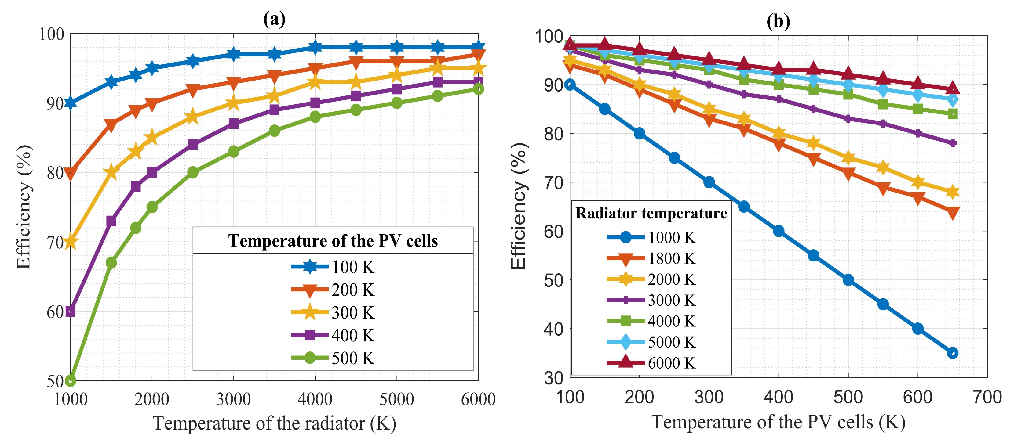
  • Investigate the effects of increasing the temperature of the radiator and TPV cells on the efficiency of a TPV system.
  • Examine the inter-relationships between the key power generation variables of a TPV system.
The scientific originality of this study was realized in the novel integration of radiative heat flux, power density output, and thermal losses that enabled physical insights into the radiation-thermodynamic phenomena within the core of TPV systems. This has not been done before, yet it is crucial in advancing the thermodynamic efficiency of TPV systems. Practically, the proposed model can facilitate the design, modelling, and optimization of TPV systems using a model-based and experimental approaches. In addition, researchers can develop sub-models of different TPV model components (i.e., the radiative heat flux, power density output, and thermal losses) towards an improvement in the TPV system performance. Furthermore, the model can inform the design of co-generation TPV systems since the model can estimate the amount of heat generated. Lastly, the model can be included as an energy conservative model in thermophotovoltaics in energy modelling software. Henceforth, Section 2 presents the description of the TPV system. Section 3 details the research approach adopted for this study, while Section 4 presents the numerical integration of the radiative heat flux, power density output and thermal losses of a TPV system. Section 5 discusses the results from the parametric studies vis-à-vis results generated from extant experimental and model-based studies. Lastly, Section 6 presents the conclusions based on the findings from the study.

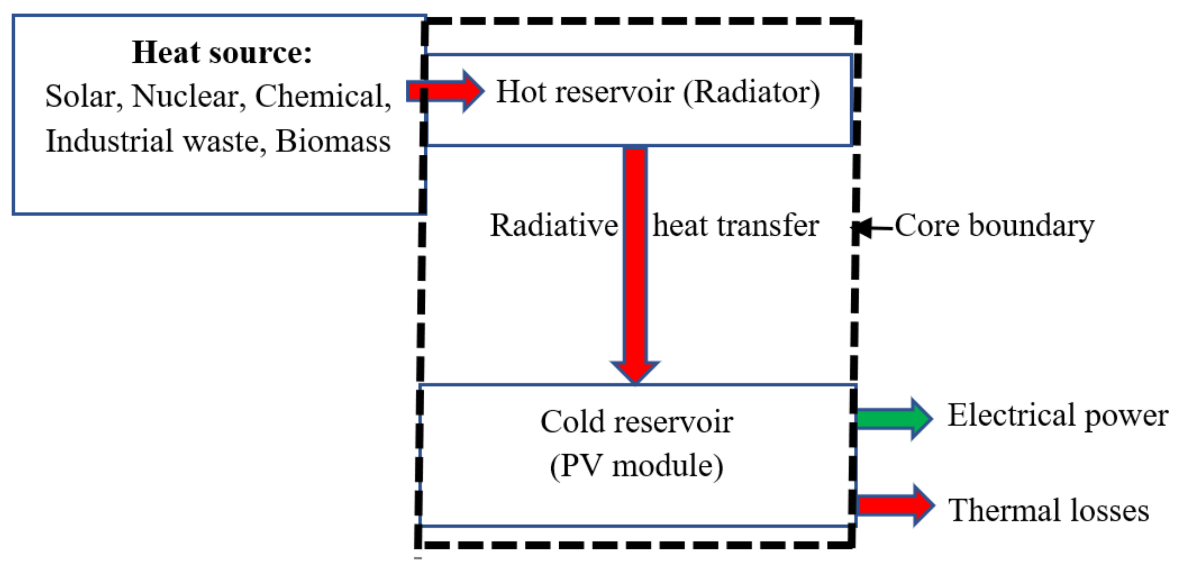
2. Description of a Thermophotovoltaic System

A typical TPV system is composed of a source of heat, a radiator/emitter, PV cells, a component for recovering sub-bandgap photons, spectral filters, a heat sink, and a DC power conditioning system [12,15]. Basically, the heat source interfaces with the radiator/emitter such that the radiative energy can be transferred to the PV cells through radiation. The PV cells then converts the radiative energy that matches its bandgap to electrical energy based on the photovoltaic process. The radiator may be made from silicon carbide or micro-structure tungsten or Welsbach-Mantle type [12]. A TPV system can be designed to include a selective filter and a reflector so that incident photons with energy below the bandgap energy of the PV cells are reflected and reabsorbed in the radiator. Recirculation of photons can be achieved with either dielectric filters with a refractive index or plasma filters, which is a transparent conducting oxide, or resonant antennae arrays which acts as an optical filter, and even back-surface reflectors that allow unabsorbed photons to be reflected back to the radiator [21]. The PV cells used in TPV systems include silicon (Si), Gallium antimonide (GaSb), copper indium gallium diselenide (CIGS), Indium gallium arsenide (InGaAs), and Germanium [21]. The overall design depends on whether the TPV system is a near-field thermophotovoltaics (NF-TPV) [28], a nano-gap TPV [29,30], or a micro-TPV [12]. This classification is based on the core distance between the radiator and the PV cells. The micro-TPV type model considered in this study has a dielectric medium between the radiator and the TPV cells. This study focuses on the core region of the system because that is the location where interaction of radiation produces electricity. Therefore, the best possible attention of the system’s energy conversion efficiency requires an improvement of its core.
An optimized core of the TPV system can easily be integrated with diverse heat sources. The heat sources for driving the radiative heat transfer may be generated from diverse sources such as nuclear, chemical, industrial waste heat, solar thermal plants, biomass plants, etc. [31]. From Figure 1, the radiation-thermodynamic model within the core region of the system was characterized by a radiative heat transfer ( H ˙ rad ) from the radiator and an electrical power ( P ˙ elect ) from the PV cells. The radiative heat flux that could not be converted into electricity resulted in a generation of thermal losses ( Q ˙ losses ) that were transferred to the heat sink as waste heat or recovered for additional thermal work, such as the heating of various types of fluids. In the current TPV model, a refractive index between 1.0 and 1.5 was used for the dielectric medium [12].

3. Research Method and Approach

Below, we describe the summary of the procedures adopted to systematically realize each of the research objectives. Photovoltaic Modelling and Simulation Code (PVMSIC) [32] in a MATLAB environment was used to implement the integration of the three sub-models of the TPV model. PVMSIC has a major advantage of accommodating user-defined functions [9]. The TPV model was validated with experimental results before it was used for a parametric study (see Section 5.1). To investigate how the variations in the radiator and PV cells temperatures affect the power generation variables of the TPV system, the interrelationships between the power generation attributes were studied using simulations and parametric studies. The code-based (CB) model of the core was simulated as the radiator temperature varies from 500 to 6000 K while the temperature of the PV cells was kept constant at 300, 400, and 500 K. This allowed the inter-relationships among the radiator temperature, photocurrent, maximum voltage, power output density, and thermal losses to be studied. The temperature of the PV cells was also varied from 300 to 700 K while maintaining the radiator temperature at 1000, 1800, and 2500 K. The inter-relationships among the photocurrent, maximum voltage, and power density output were studied to gain insights of how the power generation characteristics were affected.

4. Numerical Modelling of the Core of the Thermophotovoltaic System

Contextually, the following assumptions were made while implementing the model integration within the defined core boundary: Thermal losses from the core equaled the difference between the radiative heat flux and power density output based on the principles of conservation of energy; laws of thermodynamics and radiations were obeyed [27]; steady state condition was assumed; the emitter and the radiator of the TPV was in thermodynamic equilibrium; and there was no heat inflow into the system apart from the radiator and thermal losses exit to the heat sink [33].
The modelling assumed that the H ˙ rad from the radiator was conservatively converted into P ˙ elect and Q ˙ losses , as expressed in Equation (1) in accordance with the first law of thermodynamics. Secondly, a classical thermodynamic approach was adopted instead of statistical mechanics or quantum thermodynamics approaches so that the scope of this study was not complicated by an attempt to account for the behavior or characteristics of each photon, electron, and microstructure of the materials. Classical thermodynamics are still relevant to modern engineering thermodynamics and are suitable for gaining a global understanding of the physics of a thermodynamic system at macrostructure level [34].
Q ˙ losses   = H ˙ rad P ˙ elect
The total energy radiated ( E rad ) by a surface can be expressed by the Stefan–Boltzmann’s law, as shown in Equation (2) [15]:
  E rad = ε σ A R T rad 4
where T rad   is the temperature of the radiator, ε is emissivity, A R is the active surface area of the radiator, and σ is the Stefan–Boltzmann’s constant (5.7 × 10⁻⁸ W m−2 K−4). The surface area of the radiator is assumed to be equal and parallel to the surface area of the PV cells.
For a parallel orientation of the radiator and the TPV cells, H ˙ rad can be calculated based on Equation (3) [15]. In this modelling, n is the refractive index of the participating medium. Note that TPV cells are PV cells used in TPV systems and the two terms are used interchangeably in this study.
H ˙ rad =   n 2   ε σ   F A R   ( T rad 4 - T pv 4 )
where F is the view factor which is related to the geometrical arrangement of the system and T pv is the temperature of the PV cells.
A TPV cell is characteristic of a p-n junction with electron-hole pairs [28,29].   P ˙ elect of a TPV module can be expressed as the product of current output ( I pv ) and the voltage ( V pv ) across the terminals and can be calculated from Equation (4).
P ˙ elect   =   I pv   ×   V pv
The photocurrent I ph induced by the radiative heat flux in the TPV system is analogous to the photocurrent induced by the solar radiation in the SPV system. The photocurrent of the TPV system in relation to a reference radiative heat flux is expressed by Equation (5), which is analogous to the I ph of the SPV as applied by Bellia et al. [35].
I ph   =   (   I sc   +   K i   ( T pv     T ref ) ) H rad H ref
where I sc is the short circuit current, K i is the thermal coefficient at short circuit current, T ref is the reference temperature (298.15 K), and H ref is the reference radiative heat flux (1000 W m−2).
Supposing that the TPV system is designed with more than one TPV module, the modules are connected in parallel ( N p ) in order to increase the output current while the TPV cells in the TPV module are connected in series ( N s ) to increase the output voltage. Thus, Equation (6) can be used to compute the output current ( I pv ) from the TPV system. Substituting Equation (6) into (4), its resultant equation substituted into Equation (1) with Equation (3) yields Equation (7).
I pv   = I ph N p     I s N p exp qV pv AN s kT pv 1
Q ˙ losses   =   n 2 ε σ FA R T rad 4     T pv 4     I ph N p     I s N p exp qV pv AN s kT pv 1     ×   V pv
Winterbone and Turan [27] stated that the temperature of the hot and cold reservoirs in a Carnot engine are critical in determining its thermodynamic efficiency. The effects of variations in the temperature of the radiator and PV cells will be discussed in Section 5.4. Equation (8) expresses the thermal efficiency of the TPV system based on the radiator temperature and the temperature of the TPV cells [15].
η Th =   1   T PV T rad

5. Results and Discussion

Section 5 presents the validation of the proposed TPV model and the results generated from the simulations and parametric studies. The inter-relationships between the power generation variables were plotted to facilitate a critical analysis of their behavior in order to gain deeper insights from the studies.

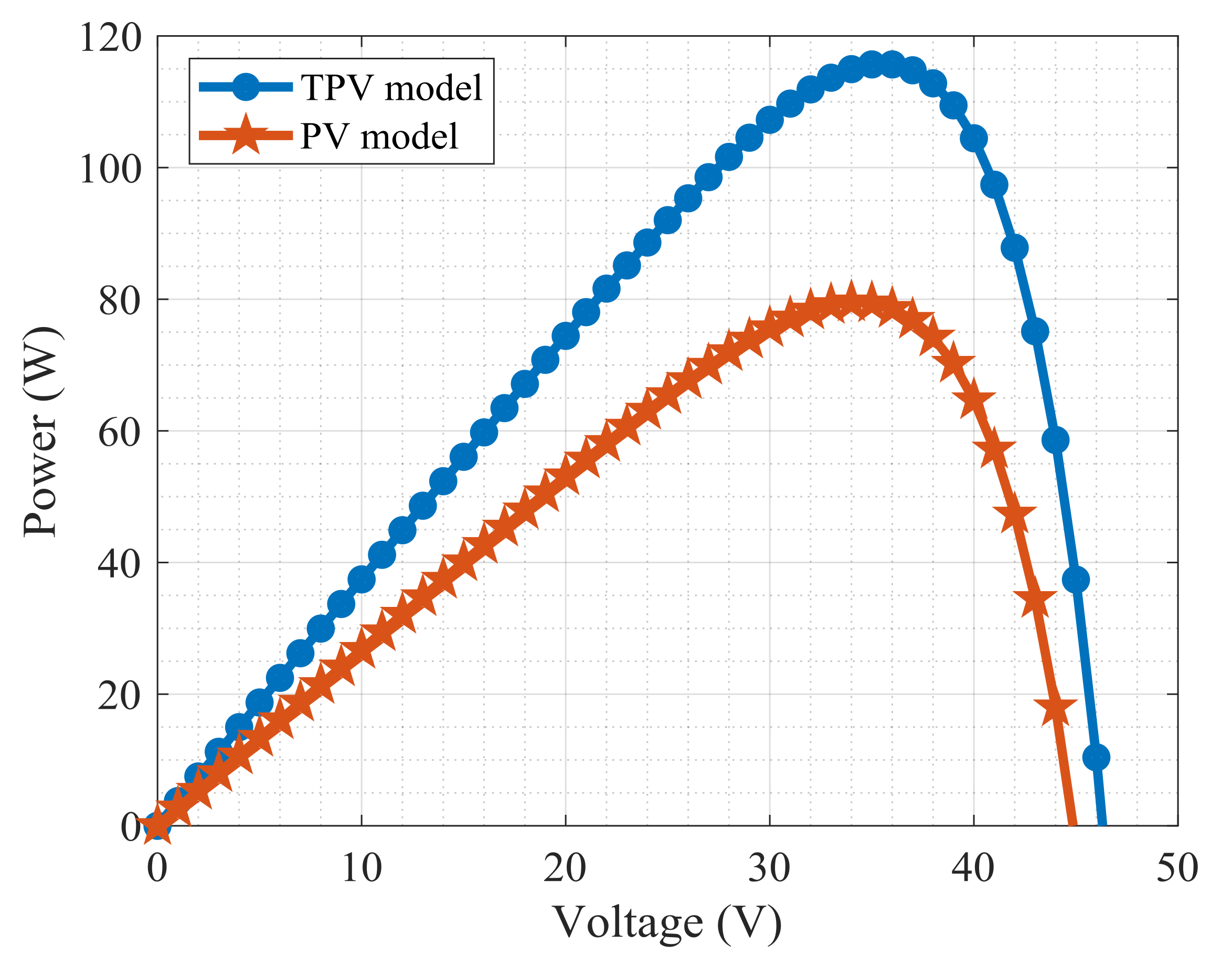
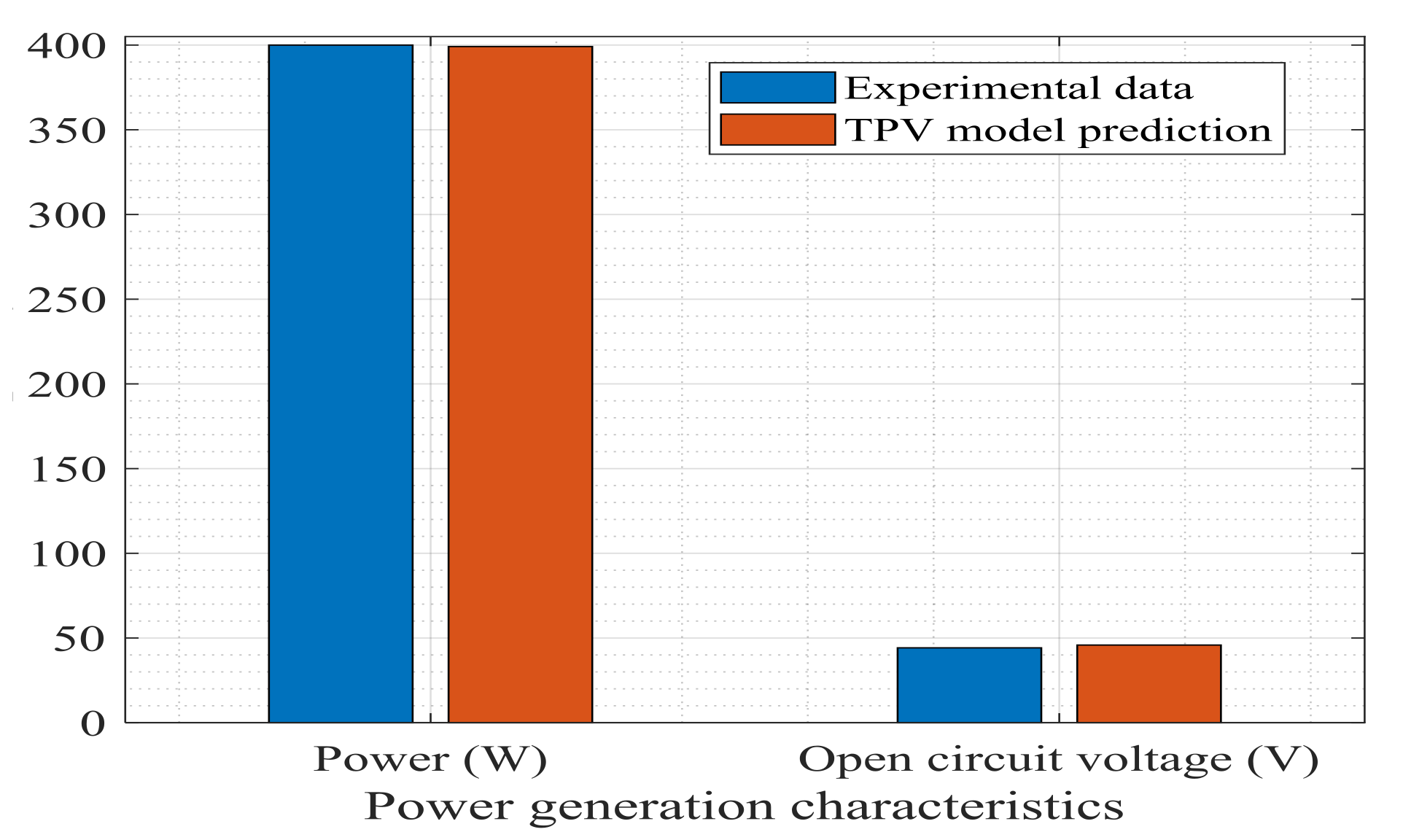
5.1. Validation of the TPV Model

The parameters of the TPV cells are often stated at STC, as exemplified by an experimental study involving butane burner with a thermal output power of 1.35 kW [36]. Here, STC specifications for the TPV cells were used to validate the TPV model. Table 1 presents the design and operational parameters of the TPV module. The proposed TPV model was subjected to two validation tests. The first test validated that the input H ˙ rad in Equation (5) did not deviate from the extant PV cell physics.
Initially, a CB model of the silicon-based 80 W PV model used in this study was created in the PVMSIC and simulated at STC. Then, a sub-model for TPV model was created with the same PV cell parameters; however, the CB model was simulated at a radiator and TPV cells temperatures of 1800 K and 300 K, respectively. In comparison, the open circuit voltage of the TPV module was more than the open circuit voltage of the SPV module. The predicted maximum power point (MPP) of the SPV module and the TPV module were 80 W and 116 W, respectively (see Figure 2). This indicated a potential 45% improvement in power generation if the characteristics of the same PV cells were applied in the TPV system. Currently, there is no standard testing conditions for TPV cells as a function of radiative heat flux such as the solar PV modules rated at standard test conditions. Thus, Figure 2 seeks to answer the question of the potential power output density of the TPV system constructed with the same PV cells rated 80 W at STC. This comparison was based on the widely reported operating temperature of the radiator and PV cells of silicon-based TPV systems at about 1800 K and 300 K, respectively [12,15].
The TPV model was also validated against a study reported in Coutts [15], which was based on GaSb PV cells and had a bandgap of 0.726 eV at 300 K. The parameters of the GaSb PV cell stated in the experimental study are the short circuit current (13.18 A), MPP (400 W), open circuit voltage (44.2), and number of PV cells (48) while the temperature of the radiator was 1700 K. From Figure 3, the predicted MPP and open circuit voltage of 399.13 W and 45.84 V, respectively, were compared with the stated MPP of 400 W and open circuit voltage of 44.2 V (Coutts [15]). The TPV model predicted the MPP and open circuit voltage at 0.87 W and 1.64 V deviations, respectively, which was acceptable for this type study.

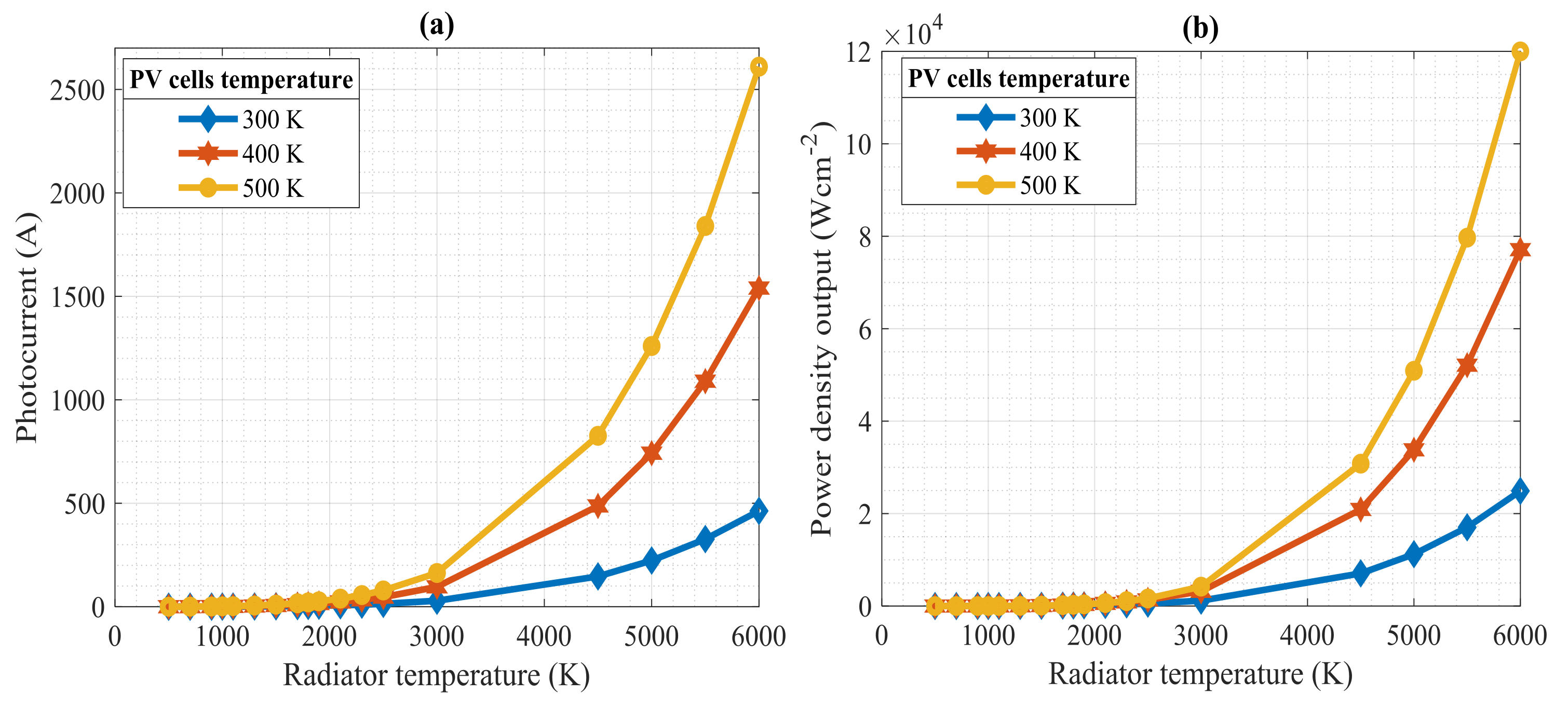
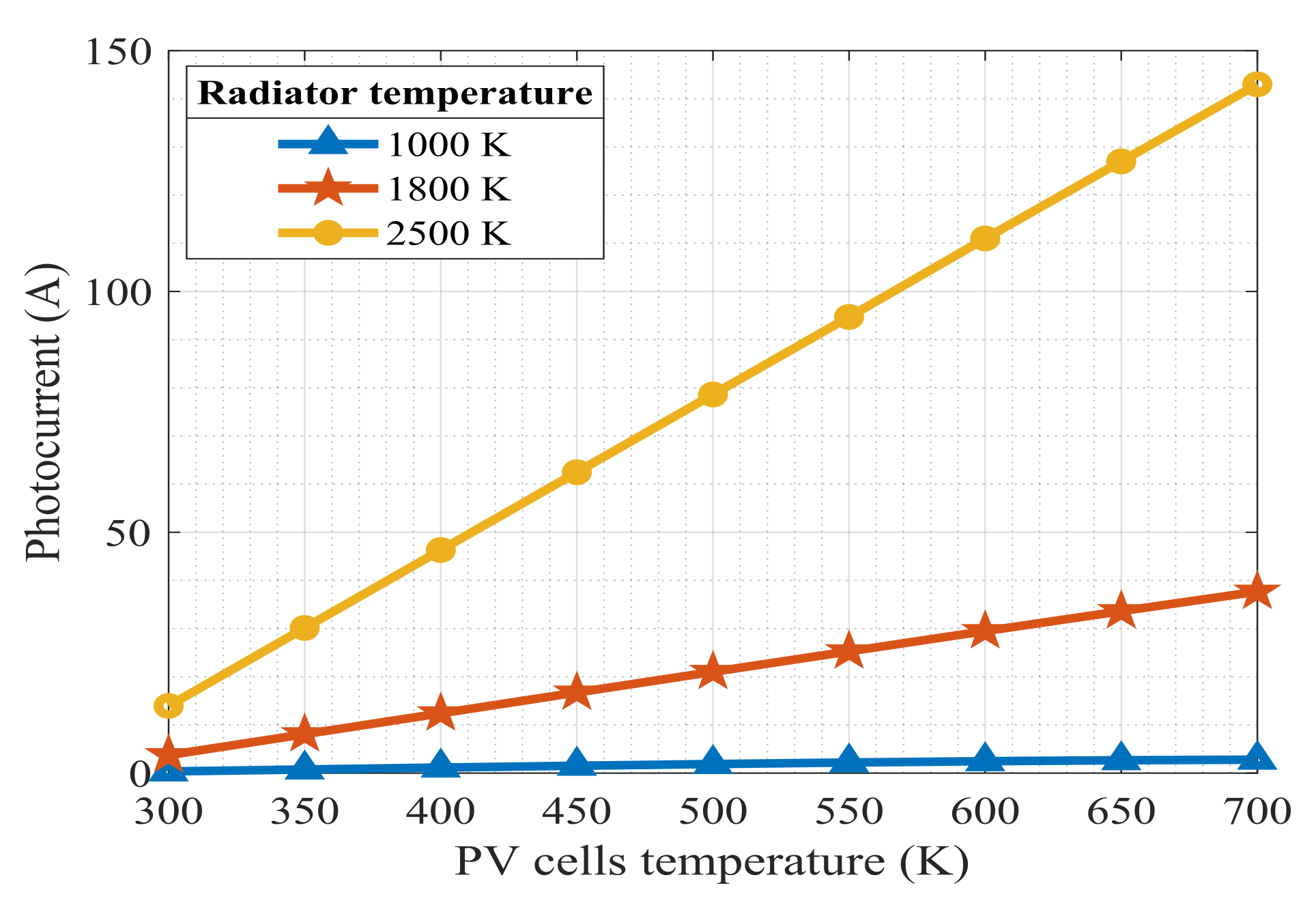
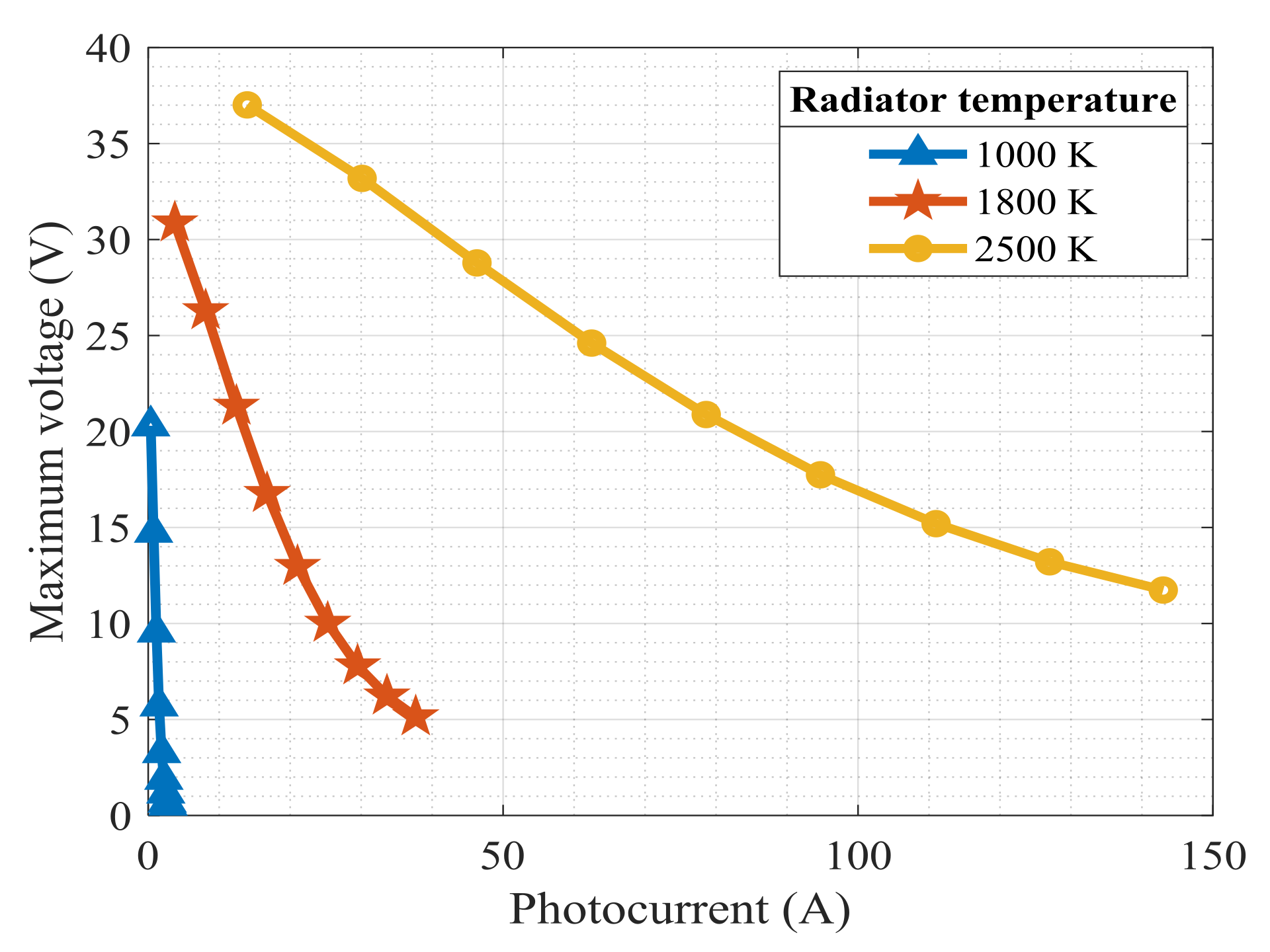
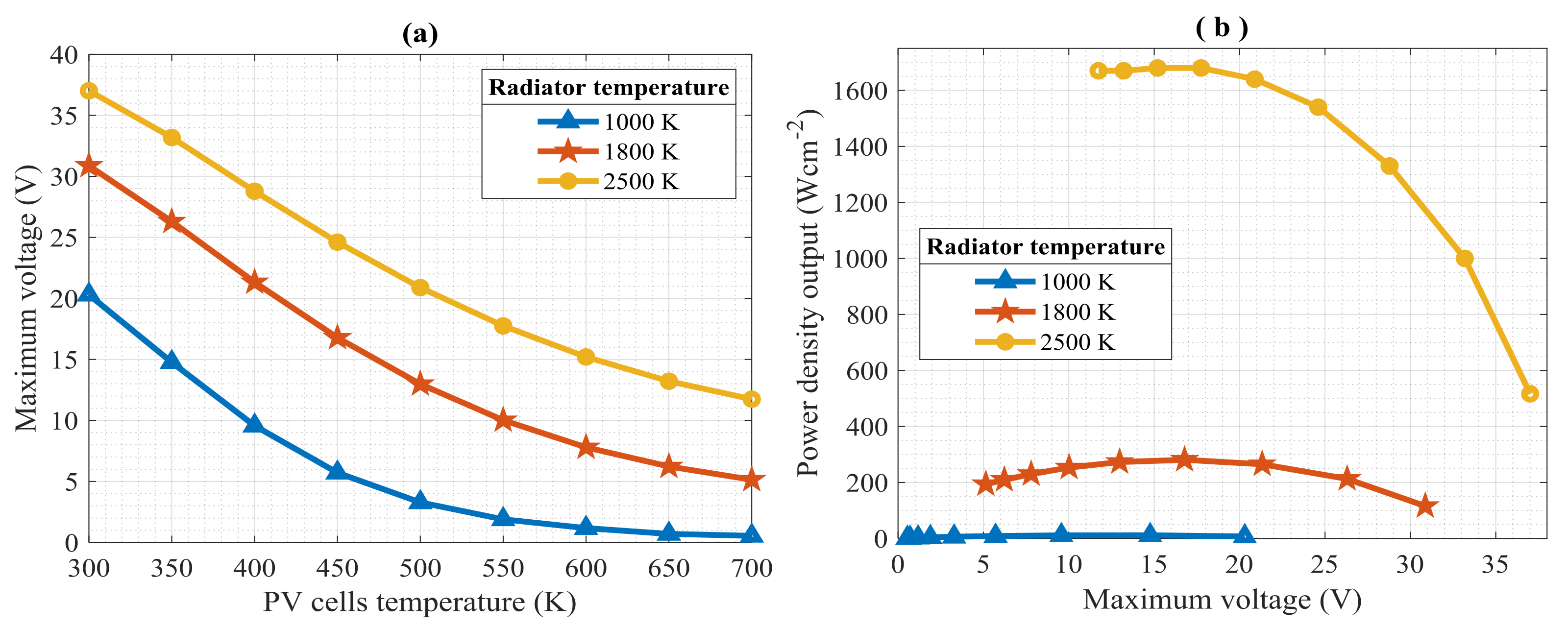
5.2. Effects of Radiator Temperature on the Power Density Output of the TPV System

Figure 4a,b show the effects of increasing the radiator temperature from 500 to 6000 K on the photocurrent and power density output of the TPV system while maintaining the temperature of the TPV cells at 300, 400, and 500 K, respectively. Clearly, the maximum power density output increased as radiator temperature increased, which was in agreement with the general principle of thermophotovoltaics—i.e., that radiative energy depends on temperature and is required to generate electricity with PV cells [15]. The radiator temperature varied with the radiative heat flux to the fourth power in accordance with the Stefan–Boltzmann law in Equation (2). Hence, the radiative heat flux increased as the temperature of the radiator increased. By extension, the photocurrent generation changed proportionally with the temperature of the radiator. There are two possible inferences that can be drawn from these results. The first inference is that photocurrent varies directly with power density output if the radiator temperature increases while the TPV cells temperature is kept constant (in this instance at 300 K).
The second inference is that the photocurrent has an exponential relationship with the radiator temperature, as shown in Figure 4a. It has been reported that silicon-based cells require a higher radiator temperature compared to TPV cells such as GaSb [39]. The design implication is that the type of the PV cell used may influence the optimal operating temperature of the TPV system. This result agrees with other studies that reported the temperature dependence of the TPV system [12,15]. There is a higher power density output when the temperature of the PV cells is kept constant at 500 K compared to when it is kept constant at 300 K. The significance of this result is that it may well be necessary to innovate high temperature PV cells for TPV applications since higher power density output can be achieved at a higher temperature. The rationale for high temperature PV cells is to generate power at high temperatures without degrading the open circuit voltage which is sensitive to the operating temperature [32] in accordance with Hottel Willier model [40].
However, in practice, the material constraints of a TPV system should be considered to avoid inducing thermal stresses in components with lower thermal capacities. Interestingly, the power density output of the TPV systems increased as the radiator temperature approached the temperature of the sun (approximately 6000 K). Although it is difficult to run a TPV system close to the temperature of the sun, our results showed that TPV systems may be applicable for designing power systems for space missions near the sun or satellites if the material constraints are addressed. Datas and Marfi [18] showed that thermophotovoltaics have potential applications in space technologies including those used near the sun with the aid of intermediate thermal storage.
From Figure 5a, the photocurrent of the TPV system increased proportionally with the radiative heat flux. This agreed with the fundamental physics of the photovoltaic effect in which energy was required to create electron-hole (E–H) pairs and the number of the E–H varied with the energy flux received by the PV cells [32]. A combined analysis of Figure 4a,b and Figure 5a,b confirmed that it was the voltage of the TPV system that was prone to non-linear variation, hence becoming more sensitive. This agreed with the findings of Jiang et al. [41] that voltage of a PV decreased with an increase in the ambient temperature, even if current increased. The exponential nature of Equation (7) that described the output current in relation to the output voltage of the TPV system also gave insight into why the power density output evolved exponentially if the radiator temperature increased. The result agreed with the conclusion of Butcher et al. [24] that oil-fired TPV system increased its power output density when the burner firing rate increased.
Figure 6 presents the relationship between the power density output and the thermal losses flux exiting the core of the TPV system into the sink. Both power density output and thermal losses flux increased as the temperature of the PV cells increased. This agreed with the first Law of thermodynamics (or conservation of energy) (Equation (1)). There were two design implications of this finding. First, the design for co-generation with TPV system may focus on efficient dissipation of thermal losses ( Q ˙ losses ) into the working fluid so that the temperature of the core can be operated below a critical PV cells temperature beyond which the open circuit voltage will degrade. The need to make a TPV system a co-generation system grows with the use of higher temperature heat source because thermal losses increase with the temperature of the radiator, as shown in Figure 6. The second design implication is that radiative energy needs to be reflected to the radiator using spectral filter and reflector to reduce the amount of thermal losses ( Q ˙ losses ) into the sink. Consequently, this methodology will yield lesser thermal losses as the recirculated radiative energy within the core needs to be instantaneously deducted from the total radiated energy from the radiator to get the thermal losses that will exit into the heat sink.

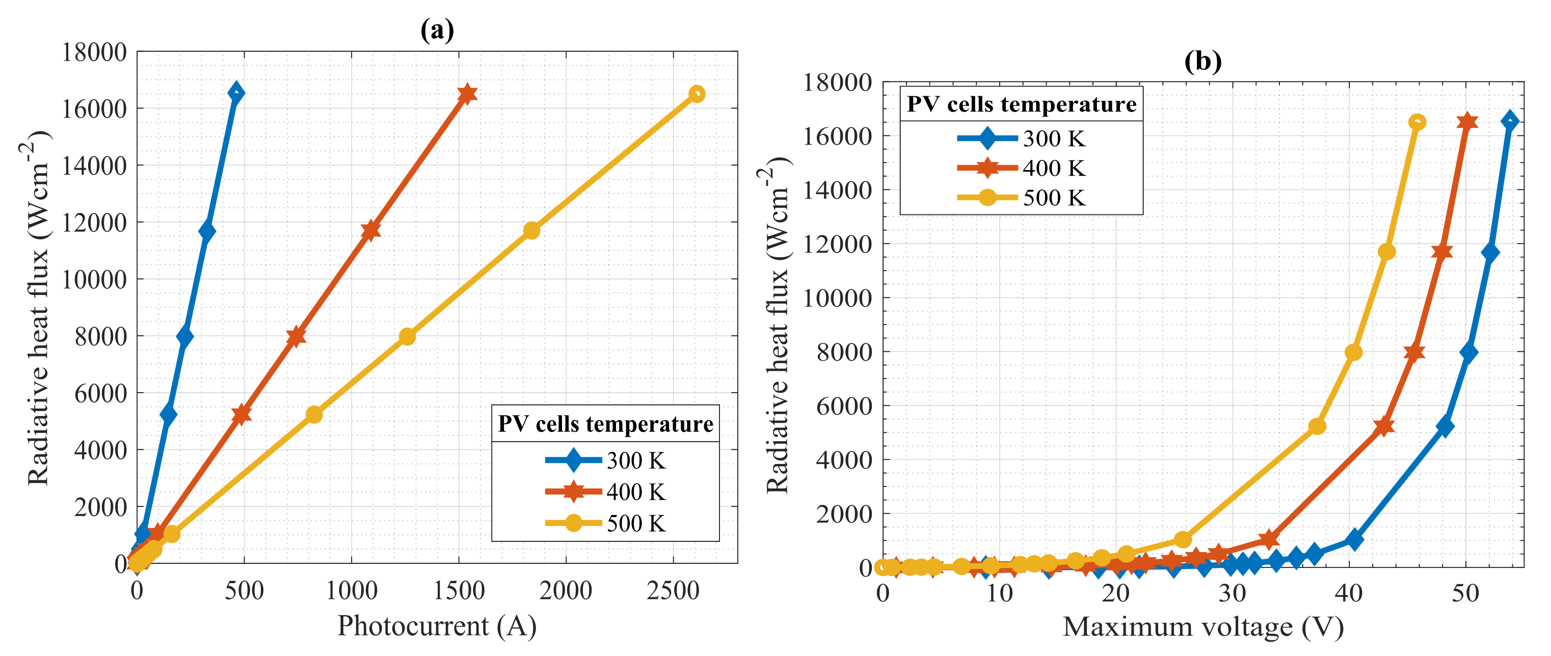
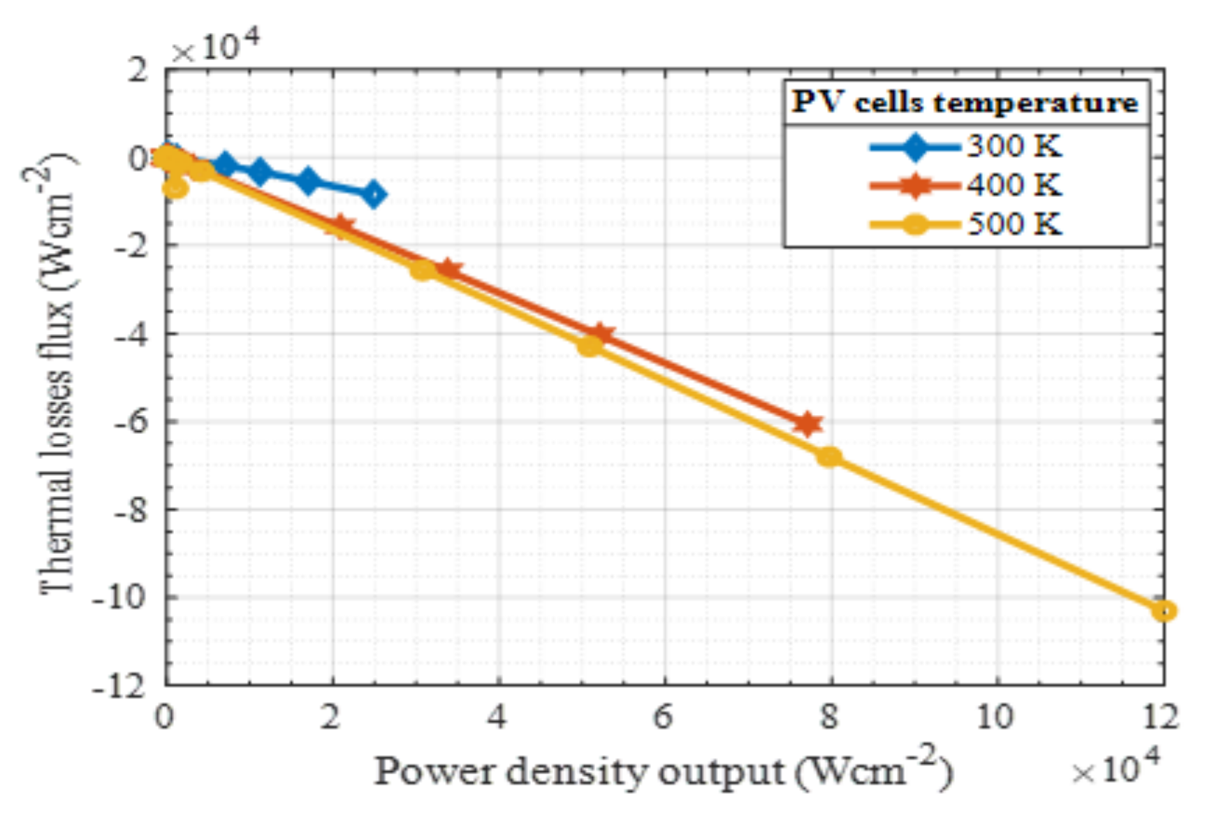
5.3. Effects of TPV Cells Temperature on the Power Generation Characteristics of the TPV System

The temperature of the radiator was maintained at 1000, 1800, and 2500 K while the temperature of the PV cells was varied from 300 to 700 K. The photocurrent varied linearly with increasing temperature of the PV cells if the radiator temperature was kept constant, as shown in Figure 7. This suggests that, if considered with Figure 5a, the photocurrent had a linear relationship with radiative heat flux and temperature of the PV cells if the temperature of the PV cells and the radiator were kept constant, respectively. The results also showed that photocurrent generation increases if the temperature of the radiator and that of the PV cells increased.
Contrarily, Figure 8 indicated that the voltage of the TPV system decreased as the temperature of the PV cells increased. This was evident in the negative slope of the photocurrent-voltage plot, given that photocurrent varied linearly with the temperature of the PV cells. Based on the physics of PV cells, electron generation in the p-n junction of semiconductor cells varied with the energy level of photons received through radiation [42]. As expected, the potential of a radiating surface to induce photocurrent generation in TPV cells increased with an increase in radiator temperature. In this case, the photocurrent increased with an increase in the radiator temperature from 1000 to 2500 K; unfortunately, the voltage output became degraded. This agreed with the extant physics of PV cells, in which increased temperature of the PV cells usually degrade the open circuit voltage and ultimately the power output from the SPV system [43].
The maximum voltage was further compared with the temperature of PV cells and power density output. When the temperature of the radiator was kept at 1000, 1800, or 2500 K, the maximum voltage decreased as the temperature of the PV cells increased, as shown in Figure 9a. From Figure 9b, when the radiator temperature was 1800 K, the maximum power density output increased up to a temperature corresponding to 450 K, but dramatically declined afterwards. This result agreed with the results generated by Durisch et al. [36] in which MPP of the TPV system decreased from 20.2 W to 15.6 W when the temperature of the TPV cells increased from 25 °C to 55 °C. Therefore, to sustain an optimal power generation as the temperature of the radiator increased, effective cooling was required to keep the temperature of the TPV cells at an optimal temperature. It appeared, however, that the power density output in relation to the maximum voltage in Figure 9b was more stable when the radiator temperature was at 1800 K compared to 2500 K. This deduction was based on the shape of the voltage-power density output curve for the radiator temperature at 1800 K, which appeared more normal than the curve at 2500 K. For the PV cells used in this study, it appeared that operating it at 1800 K gave better stability and factor of safety since the power density output formed a bell shape or normal distribution.

5.4. Thermal Efficiency of the TPV System

The thermal efficiency of the TPV system as a function of the temperatures of the radiator and PV cells were studied in order to investigate the effects of increasing the temperature of the radiator and TPV cells on the efficiency of a TPV system. From Figure 10a, the thermal efficiency (see Equation (8)) of the TPV system increased as the temperature of the PV cells reduced. Clearly, the efficiency trajectory of the TPV system was higher when the PV cells temperature was maintained at the lowest possible temperature, while the temperature of the radiator was kept constant (in this instance at 1800 K). On the other hand, from Figure 10b, the thermal efficiency increased as the temperature of the radiator increased from 1000 to 6000 K if the temperature of the PV cells was kept constant (i.e., at 300 K). Therefore, higher power generation efficiency can be obtained from the TPV system by matching the optimal temperatures of the radiator and PV cells. The optimal design should seek a point of convergence of the critical temperature of the radiator and the PV cells beyond which the open circuit voltage will degrade. This is important in conceptualizing the TPV system as a heat engine because the foregoing results have shown that it is not as straightforward as altering the temperature of the reservoirs given that the open circuit voltage of the TPV cells varies non-linearly with the radiator and the PV cells temperatures. However, the wider implication of the thermal efficiency of the TPV system is that the PV cells should be effectively cooled while the radiator should be heated to widen the difference in temperature so that efficiency can be improved. Nonetheless, cooling consumes power produced which reduces the net power output from the system.

6. Conclusions

This study presented a novel integration of the radiative heat flux, power density output, and thermal losses of a thermophotovoltaic (TPV) system using photovoltaic modelling and simulation code approach. This involved creating new codes for the radiative heat flux and thermal losses sub-models. After coupling and validating the proposed thermophotovoltaic model, simulations, and parametric studies were carried out with the radiator temperature varying from 500 to 6000 K at a constant PV cells temperature. Again, the temperature of the photovoltaic (PV) cells varied from 300 to 700 K while the temperature of the radiator remained constant. The results indicated that the power density output increased with an increase in the radiator temperature if the temperature of the PV cells was maintained at 300 K temperature. Unfortunately, the open circuit voltage decreased as the temperature of the PV cells increased from 300 to 700 K even if the radiator temperature was kept constant.
At a radiator temperature of 1800 K and TPV cells temperature of 300 K, the TPV model predicted the power density output, thermal losses, and maximum voltage of the TPV system as 115.68 W cm−2, 18.14 W cm−2 and 36 V, respectively. Hence, for the 80W PV module used in this study, there was a potential 45% improvement in power generation capacity if it was applied in a TPV system with an effectively matched radiator and PV cells characteristics at a radiator temperature of 1800 K and TPV cells temperature of 300 K. The thermal efficiency of the TPV system appeared to be higher when the TPV cell temperature was low, as well as if the radiator temperature increased while the PV cells temperature was maintained at a low temperature through appropriate thermal dissipation or recovery strategy.
The significance of this study is that the proposed TPV model in Equation (7) showed positive results as a potential radiation-thermodynamic model for gaining physical insights into the core region of a TPV system. In our future work, the results from this work will be leveraged to develop and integrate additional sub-models to include parameters such as the wavelength of the radiation to further expand the scope and application of the proposed model. Within the limits of the assumptions in this study, the novel TPV model did not contravene extant thermodynamic, radiation, and photovoltaic laws. It is therefore recommended to scientists and engineers for consideration in model-based and experimental studies of TPV systems.

Author Contributions

Conceptualization, C.O.; data curation, C.O.; formal analysis, C.O.; funding acquisition, C.O.; investigation, C.O. and A.T.; methodology, C.O.; project administration, C.O.; resources, A.T., A.N., and C.A.; software, C.O.; supervision, A.T., C.A., and A.N.; validation, C.O.; visualization, C.O.; roles/writing–original draft, C.O.; writing–review and editing, C.O., A.T., C.A., and A.N. All authors have read and agreed to the published version of this manuscript.

Funding

This work was funded by a scholarship of the Petroleum Technology Development Fund (PTDF) Nigeria number PTDF/ED/PHD/OC/1078/17.

Conflicts of Interest

The authors declare no conflict of interest. The funders had no role in the design of the study; in the collection, analyses, or interpretation of data; in the writing of the manuscript, or in the decision to publish the results.

Nomenclatures/Abbreviations

CBMcode-based modelling/model
H ˙ rad radiative heat flux (W cm−2)
H ref reference radiative heat flux (1000 W m−2)
I ph photocurrent of PV module
I pv output current of PV module
I s saturation current of PV module
I sc short circuit current of PV module
kBoltzmann’s constant (1.38 × 10⁻²³ J K−1)
nrefractive index of the dielectric medium
N s number of PV cells in series
N p number of PV modules in parallel
PVphotovoltaic
PVMSICphotovoltaic modelling and simulation codes
qelectron charge (1.602 × 10⁻¹⁹ C)
Q ˙ losses thermal losses from the TPV system (W cm−2)
STCstandard test condition for PV cells (298.15 K, 1000 W m−2, AM 1.5)
TPVthermophotovoltaic
T pv   temperature of the PV cells
T Rad   temperature of the radiator (K)
T ref   reference temperature (298.15 K)
P ˙ elect power density output (W cm−2)
Greek symbols
ε emissivity
ηenergy efficiency
σ Stefan-Boltzmann’s constant (5.67 × 10⁻¹² W cm−2 K−4)
Subscripts
cellPV cell
phphoton
pvphotovoltaic
radradiative
refreference
Ththermal

References

  1. Ogbonnaya, C.; Abeykoon, C.; Damo, U.M.; Turan, A. The current and emerging renewable energy technologies for power generation in Nigeria: A review. Therm. Sci. Eng. Prog. 2019, 13, 100390. [Google Scholar] [CrossRef]
  2. MacKay, D.J. Sustainable Energy—Without the Hot Air; UIT Cambridge Ltd.: Cambridge, UK, 2009; p. 383. [Google Scholar] [CrossRef]
  3. United Nations Framework Convention on Climate Change, EU. Paris Agreement; UNFCCC: Paris, France, 2016.
  4. Dasanayaka, C.H.; Abeykoon, C.; Nagirikandalage, P. Modelling of the effects of renewable energy establishments towards the economic growth of a nation. In Proceedings of the 7th International Conference on Fluid Flow, Heat and Mass Transfer (FFHMT’20), Niagara Falls, ON, Canada, 15–17 November 2020. [Google Scholar]
  5. Mahmud, M.A.P.; Huda, N.; Farjana, S.H.; Lang, C. Environmental impacts of solar-photovoltaic and solar-thermal systems with life-cycle assessment. Energies 2018, 11, 2346. [Google Scholar] [CrossRef] [Green Version]
  6. Ogbonnaya, C.; Turan, A.; Abeykoon, C. Energy and exergy e ffi ciencies enhancement analysis of integrated photovoltaic-based energy systems. J. Energy Storage 2019, 26, 101029. [Google Scholar] [CrossRef]
  7. REN21 Renewables 2018 Global Status Report. Paris Renewable Energy Policy Network 21st Century; REN21 Secretariat: Paris, France, 2018; pp. 1–324. ISBN 978-3-9818911-3-3. [Google Scholar]
  8. Luque, A. Will we exceed 50% efficiency in photovoltaics? J. Appl. Phys. 2011, 110, 031301. [Google Scholar] [CrossRef]
  9. Ogbonnaya, C.; Turan, A.; Abeykoon, C. Novel thermodynamic efficiency indices for choosing an optimal location for large-scale photovoltaic power generation. J. Clean. Prod. 2019, 119405. [Google Scholar] [CrossRef]
  10. Ogbonnaya, C.; Turan, A.; Abeykoon, C. Modularization of integrated photovoltaic-fuel cell system for remote distributed power systems. In Industry 4.0—Shaping The Future of The Digital World; da Silva Bartolo, P.J., da Silva, F.M., Jaradat, S., Bartolo, H., Eds.; CRC Press: Manchester, UK, 2020; pp. 303–308. ISBN 9780367823085. [Google Scholar]
  11. Chowdhury, N.; Hossain, C.A.; Longo, M.; Yaïci, W. Optimization of solar energy system for the electric vehicle at university campus in Dhaka, Bangladesh. Energies 2018, 11, 2433. [Google Scholar] [CrossRef] [Green Version]
  12. Bauer, T. Thermophotovoltaics: Basic Principles and Critical Aspects of System Design (Green Energy Technology); Springer: Berlin/Heidelberg, Germany, 2011. [Google Scholar] [CrossRef]
  13. Seyf, H.R.; Henry, A. Thermophotovoltaics: A potential pathway to high efficiency concentrated solar power. Energy Environ. Sci. 2016, 9, 2654–2665. [Google Scholar] [CrossRef]
  14. Durisch, W.; Bitnar, B.; Mayor, J.C.; von Roth, F.; Sigg, H.; Tschudi, H.R.; Palfinger, G. Small self-powered grid-connected thermophotovoltaic prototype system. Appl. Energy 2003, 74, 149–157. [Google Scholar] [CrossRef]
  15. Coutts, T.J. Review of progress in thermophotovoltaic generation of electricity. Renew. Sustain. Energy Rev. 1999, 3, 77–184. [Google Scholar] [CrossRef]
  16. Aberoumand, S.; Ghamari, S.; Shabani, B. Energy and exergy analysis of a photovoltaic thermal (PV/T) system using nanofluids: An experimental study. Sol. Energy 2018, 165, 167–177. [Google Scholar] [CrossRef]
  17. Damo, U.M.; Ferrari, M.L.; Turan, A.; Massardo, A.F. Re-compression model for SOFC hybrid systems: Start-up and shutdown test for an emulator rig. Fuel Cells 2015, 15, 42–48. [Google Scholar] [CrossRef]
  18. Datas, A.; Martí, A. Thermophotovoltaic energy in space applications: Review and future potential. Sol. Energy Mater. Sol. Cells 2017, 161, 285–296. [Google Scholar] [CrossRef]
  19. Hussain, C.M.I.; Duffy, A.; Norton, B. Thermophotovoltaic systems for achieving high-solar-fraction hybrid solar-biomass power generation. Appl. Energy 2020, 259, 114181. [Google Scholar] [CrossRef]
  20. Zhou, Z.; Sakr, E.; Sun, Y.; Bermel, P. Solar thermophotovoltaics: Reshaping the solar spectrum. Nanophotonics 2016, 5, 1–21. [Google Scholar] [CrossRef]
  21. Daneshvar, H.; Prinja, R.; Kherani, N.P. Thermophotovoltaics: Fundamentals, challenges and prospects. Appl. Energy 2015, 159, 560–575. [Google Scholar] [CrossRef]
  22. Harder, N.P.; Würfel, P. Theoretical limits of thermophotovoltaic solar energy conversion. Semicond. Sci. Technol. 2003, 18. [Google Scholar] [CrossRef]
  23. Ferrari, C.; Melino, F.; Pinelli, M.; Spina, P.R. Thermophotovoltaic energy conversion: Analytical aspects, prototypes and experiences. Appl. Energy 2014, 113, 1717–1730. [Google Scholar] [CrossRef]
  24. Butcher, T.A.; Hammonds, J.S.; Horne, E.; Kamath, B.; Carpenter, J.; Woods, D.R. Heat transfer and thermophotovoltaic power generation in oil-fired heating systems. Appl. Energy 2011, 88, 1543–1548. [Google Scholar] [CrossRef]
  25. Lu, Q.; Zhou, X.; Krysa, A.; Marshall, A.; Carrington, P.; Tan, C.H.; Krier, A. InAs thermophotovoltaic cells with high quantum efficiency for waste heat recovery applications below 1000 °C. Sol. Energy Mater. Sol. Cells 2018, 179, 334–338. [Google Scholar] [CrossRef] [Green Version]
  26. Gentillon, P.; Singh, S.; Lakshman, S.; Zhang, Z.; Paduthol, A.; Ekins-Daukes, N.J.; Chan, Q.N.; Taylor, R.A. A comprehensive experimental characterisation of a novel porous media combustion-based thermophotovoltaic system with controlled emission. Appl. Energy 2019, 254, 113721. [Google Scholar] [CrossRef]
  27. Winterbone, D.E.; Turan, A. Advanced Thermodynamics for Engineers, 2nd ed.; Butterworth-Heinemann: Oxford, UK, 2015; ISBN 9780080999838. [Google Scholar]
  28. Laroche, M.; Carminati, R.; Greffet, J.J. Near-field thermophotovoltaic energy conversion. J. Appl. Phys. 2006, 100, 063704. [Google Scholar] [CrossRef]
  29. Lau, J.Z.J.; Wong, B.T. Thermal energy conversion using near-field thermophotovoltaic device composed of a thin-film tungsten radiator and a thin-film silicon cell. J. Appl. Phys. 2017, 122, 084302. [Google Scholar] [CrossRef]
  30. Maremi, F.T.; Lee, N.; Choi, G.; Kim, T.; Cho, H.H. Design of multilayer ring emitter based on metamaterial for thermophotovoltaic applications. Energies 2018, 11, 2299. [Google Scholar] [CrossRef] [Green Version]
  31. Bitnar, B.; Durisch, W.; Holzner, R. Thermophotovoltaics on the move to applications. Appl. Energy 2013, 105, 430–438. [Google Scholar] [CrossRef]
  32. Ogbonnaya, C.; Turan, A.; Abeykoon, C. Robust code-based modeling approach for advanced photovoltaics of the future. Sol. Energy 2020, 199, 521–529. [Google Scholar] [CrossRef]
  33. Bunge, M. A General Black Box Theory. Philos. Sci. 1963, 30. [Google Scholar] [CrossRef]
  34. Kreith, F. CRC Handbook of Thermal Engineering; CRC Press: Boca Raton, FL, USA, 1999; ISBN 084939581X. [Google Scholar]
  35. Bellia, H.; Youcef, R.; Fatima, M. A detailed modeling of photovoltaic module using MATLAB. NRIAG J. Astron. Geophys. 2014, 3, 53–61. [Google Scholar] [CrossRef] [Green Version]
  36. Durisch, W.; Grob, B.; Mayor, J.-C.; Panitz, J.-C.; Rosselet, A. Interfacing a small thermophotovoltaic generator to the grid. AIP Conf. Proc. 2011, 403, 403–416. [Google Scholar] [CrossRef]
  37. Meyer, E.L. Extraction of Saturation Current and Ideality Factor from Measuring Voc and Isc of Photovoltaic Modules. Int. J. Photoenergy 2017, 2017. [Google Scholar] [CrossRef] [Green Version]
  38. Varshni, Y.P. Temperature dependence of the energy gap in semiconductors. Physica 1967, 34, 149–154. [Google Scholar] [CrossRef]
  39. Bhatt, R.; Kravchenko, I.; Gupta, M. High-efficiency solar thermophotovoltaic system using a nanostructure-based selective emitter. Sol. Energy 2020, 197, 538–545. [Google Scholar] [CrossRef]
  40. Florschuetz, L.W. Extension of the Hottel-Whillier model to the analysis of combined photovoltaic/thermal flat plate collectors. Sol. Energy 1979, 22, 361–366. [Google Scholar] [CrossRef]
  41. Jiang, J.A.; Wang, J.C.; Kuo, K.C.; Su, Y.L.; Shieh, J.C.; Chou, J.J. Analysis of the junction temperature and thermal characteristics of photovoltaic modules under various operation conditions. Energy 2012, 44, 292–301. [Google Scholar] [CrossRef]
  42. Nelson, J. The Physics of Solar Cells; Imperial College Press: London, UK, 2003; p. 384. [Google Scholar]
  43. Ogbonnaya, C.; Turan, A.; Abeykoon, C. Numerical integration of solar, electrical and thermal exergies of photovoltaic module: A novel thermophotovoltaic model. Sol. Energy 2019, 185, 298–306. [Google Scholar] [CrossRef]
Figure 1. Diagram of the energy conservation of the core of the thermophotovoltaic (TPV) system.
Energies 13 06157 g001
Figure 2. Photovoltaic Modelling and Simulation Codes predicted power: voltage curves for PV and TPV models.
Energies 13 06157 g002
Figure 3. Comparison between predicted and experimental values of power generation characteristics.
Energies 13 06157 g003
Figure 4. Relationship between (a) radiator temperature and photocurrent, (b) radiator temperature and power density output at a constant PV cells temperature at 300 K.
Energies 13 06157 g004
Figure 5. Relationship between (a) photocurrent and radiative heat flux, (b) maximum voltage, and radiative heat flux for PV cells temperatures at 300, 400, and 500 K.
Energies 13 06157 g005
Figure 6. Relationship between power density output and thermal heat flux of the TPV system when the temperature of the TPV cells is at 300, 400, and 500 K.
Energies 13 06157 g006
Figure 7. Relationship between PV cells temperature and photocurrent of the TPV system when the temperature of the radiator is at 1000, 1800, and 2500 K.
Energies 13 06157 g007
Figure 8. Relationship between photocurrent and maximum voltage of the TPV system when the temperature of the radiator at 1000, 1800, and 2500 K while the PV cells vary from 300 to 700 K.
Energies 13 06157 g008
Figure 9. Relationship between (a) PV cells temperature and maximum voltage, (b) maximum voltage, and power density outputs for radiator temperature at 1000, 1800, and 2500 K.
Energies 13 06157 g009
Figure 10. Thermal efficiency of the TPV system: (a) Effects of increasing the radiator temperature on efficiency; (b) effects of increasing the PV cells temperature on efficiency.
Energies 13 06157 g010
Table 1. Design and operational parameters of the thermophotovoltaic module.
ParametersValuesUnitsReferences
Temperature of the radiator ( T R )1800KBauer [12]
Temperature of the TPV cells ( T p v )300KBauer [12]
Maximum Power Point (at T R = 1800   K ,   T PV = 300   K )116WPVMIC [32]
Reference temperature ( T ref )298.15KBauer [12]
Refractive index of the medium (n)1.5 Bauer [12]
View factor (parallel configuration) (F)1 Bauer [12]
Reference radiative heat transfer ( H ref )1000W m−2PVMIC [32]
Emissivity of the radiator ( ε R )1 Bauer [12]
Short circuit current of TPV cells ( I sc )2.68APVMIC [32]
Saturation current of   the   TPV   cells   ( I s )5.39 × 10⁻⁵AMeyer [37]
Maximum Power Point ( P mp ) (at STC)80WattsPVMIC [32]
Maximum Voltage Point ( V mp )35VPVMIC [32]
Ideality factor (A) 2.85 PVMIC [32]
Band gap (Silicon) at 0 K1.17eVVarshni [38]
Number of cells in series ( N s )72 PVMIC [32]
Number of cells in parallel ( N p )1 PVMIC [32]
Boltzmann constant (k)1.38 × 10⁻²³J K−1Coutts [15]
Electron Charge (q)1.602 × 10⁻¹⁹CCoutts [15]
Stefan–Boltzmann constant ( σ )5.67 × 10⁻⁸W m−2 K−4Coutts [15]
Number of simulation iterations700 PVMIC [32]
Publisher’s Note: MDPI stays neutral with regard to jurisdictional claims in published maps and institutional affiliations.

