Article

Performance Improvement of Condensation Reduction and Removal in Heat Recovery Ventilators Using Purge Methods

Department of Mechanical Engineering, Korea University, 145 Anam-ro, Seongbuk-gu, Seoul 02841, Korea
*
Author to whom correspondence should be addressed.
Energies 2020, 13(22), 6152; https://doi.org/10.3390/en13226152
Submission received: 23 October 2020 / Revised: 16 November 2020 / Accepted: 18 November 2020 / Published: 23 November 2020
(This article belongs to the Special Issue Ventilation and Building Energy Systems)

Abstract

:
In this study, several purge and ventilation methods are proposed to reduce and remove condensation in a heat recovery ventilator for commercial and household buildings. The effects of the airflow rate, duration of ventilation, purge interval, and return air temperature on the quantities of condensation and condensation removal in the heat recovery ventilator are analyzed. The increase in the air flow rate and return air temperature increases the condensation removal rate owing to the enhanced evaporation of the condensate. Furthermore, the reductions in the duration of ventilation and purge interval decreased the accumulation of condensate on the heat exchanger element. Based on the experimental results, optimum ventilation and purge strategies are proposed according to the outdoor temperature. The operation of the heat recovery ventilator with the proposed ventilation and purge strategies shows at least a 33% and up to an 80% reduction in the quantity of condensate compared with a given operation method. Accordingly, the proposed operation strategies can significantly reduce the growth of microorganisms and fungi and also increase the efficiency of a heat recovery ventilator. However, further investigation on the detailed performance according to the outdoor humidity and overall energy analysis is necessary to supplement the limitations of this study.

1. Introduction

To combat increasing air pollution and the presence of fine particulates, heat recovery ventilators have been introduced in commercial and household buildings. When air is expelled to the outside through the heat recovery ventilator, heat is exchanged between the exhausted indoor air and the supplied outside air (OA) via a heat exchange element. Therefore, the heat recovery ventilator provides fresh air into a room with a minimum amount of energy loss. However, during winter, condensation occurs in the heat recovery ventilator due to the heat exchange between the cold OA and warm inside air. Furthermore, the heat recovery ventilator can be frozen when exposed to the freezing OA, which decreases its performance and ultimately results in failure. In addition, during summer, both the humid climatic conditions and a large indoor-outdoor temperature difference causes condensation in the heat recovery ventilator. The generated moisture promotes the growth of microorganisms and fungi, which may be hazardous to the health and comfort of residents. Accordingly, condensation reduction and removal in a heat recovery ventilator are essential for maintaining healthy and comfortable environments with high energy-saving performance.
The performance characteristics of heat recovery ventilators have been extensively studied. Choi and Song [1] evaluated the performance of a heat recovery ventilator under different outdoor conditions and found that a greater indoor-outdoor temperature difference led to a higher total heat exchange efficiency. Lee et al. [2] reported no change in the latent heat exchange effectiveness with respect to the air temperature and relative humidity; however, the latent heat exchange effectiveness was affected by the absolute humidity. Chun et al. [3] conducted experiments to analyze the ventilation performance of a hybrid ventilation system in small multi-unit dwellings and validated its feasibility. Kang et al. [4] developed energy-saving ventilation equipment with a high-efficiency heat exchanger element. Lim et al. [5] conducted an experiment on the airflow rates of the supply air (SA) and exhaust air (EA) of a heat recovery ventilator, proposing the optimum airflow rate. Kim et al. [6] used a numerical technique to present an efficient ventilation method for multi-unit dwellings, and Kim and Rhee [7] comparatively analyzed the air change efficiency of a ceiling duct type and wall type units, presenting the optimum ventilation choice and installation position. Some studies regarding thermochemical recuperation, which recovers chemical energy from exhaust gases, also have been carried out. Pashchenko [8] investigated the performance of thermochemical recuperation used in ethanol-steam reforming system according to the temperature, pressure, and steam-to-ethanol ratio. Pashchenko et al. [9] studied the performance of thermochemical waste-heat recuperation for reforming of biofuels such as methanol, ethanol, n-butane, and glycerol. The authors suggested effective temperatures for all the tested biofuel, providing a useful reference to select the type of fuel for the thermochemical recuperation. In summary, the fundamental studies on the performance of the ventilation system according to the operating conditions have already been conducted.
Several studies have been conducted on the energy savings of heat recovery ventilators. Yee and Kim [10] suggested that the energy consumption of heat recovery ventilators for multi-unit dwellings could be reduced by switching to a bypass mode depending on the indoor and outdoor conditions. Jung and Chae [11] discovered that the installation of plate-type heat recovery ventilators reduced the overall heating load. Kim et al. [12] found that the total energy consumption of natural ventilators was higher than that of mechanical ventilators in the case of small multi-unit dwellings. In the case of multi-unit dwellings, Kim and Park [13] reported very little difference in the annual energy consumption of systems with and without a heat recovery ventilator. Park et al. [14] evaluated the energy-saving effect of a heat recovery ventilator compared to conventional systems through a TRNSYS simulation [15]. Kim et al. [16] compared the energy consumption of the cooling and heating operations of a heat recovery ventilator, reporting no statistical difference between the two operations. Therefore, existing studies support findings that heat recovery ventilators consume less energy than conventional ventilation systems.
However, as previous mentioned, the condensation in the heat recovery ventilator may cause critical problems; therefore, several previous studies have investigated the basic processes and phenomena of condensation in heat recovery ventilators. Nam et al. [17] reported that as the flow rate of SA decreased, the dew point temperature of the EA also decreased, increasing the amount of condensation on the cold walls of the heat recovery ventilator. Kim and Jeong [18] investigated the processes of condensation and freezing that may occur during operation in winter. They reported that condensation and freezing can be solved by suppressing condensation through preheating. Jeon et al. [19] proposed an operating strategy for a ventilator to prevent condensation by changing the operating temperature and dimensions of the heat recovery ventilator.
Existing studies on the reduction and removal methods for condensation in heat recovery ventilators have focused on preheating the OA, reheating the EA, and intermittent operation. A purge method is expected to reduce and remove condensation in a heat recovery ventilator with high energy efficiency and comfort. However, comprehensive experimental studies on the purge method in heat recovery ventilators are very limited in the open literature. Moreover, an intensive study on the performance of the heat recovery ventilator using the purge method to remove condensation is essential because the purge method affects the heat transfer performance of the heat recovery ventilator. In this study, the effects of the purge method on the performance and comfort of a heat recovery ventilator were investigated through experiments. The reduction and removal of condensation using the purge method in the heat recovery ventilator were measured and analyzed by varying the duration and interval of purge as well as the airflow rate. The tested purge methods included conventional purge, circulation purge, heat purge, and outward purge. Based on the test results, optimum ventilation and purge strategies were proposed at different outdoor temperatures. The measured data can provide useful guidelines for determining the operating conditions as well as the ventilation and purge strategies in the heat recovery ventilator.

2. Experimental Setup and Test Procedure

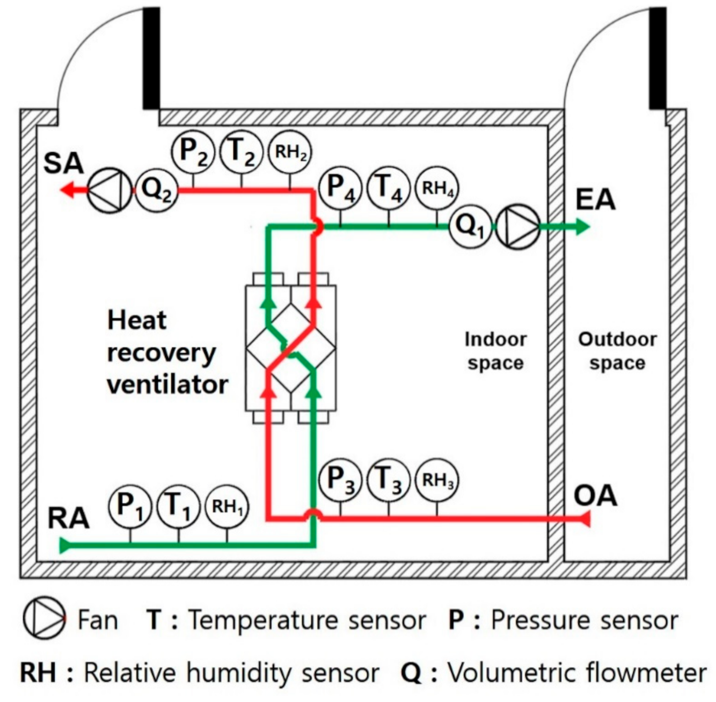
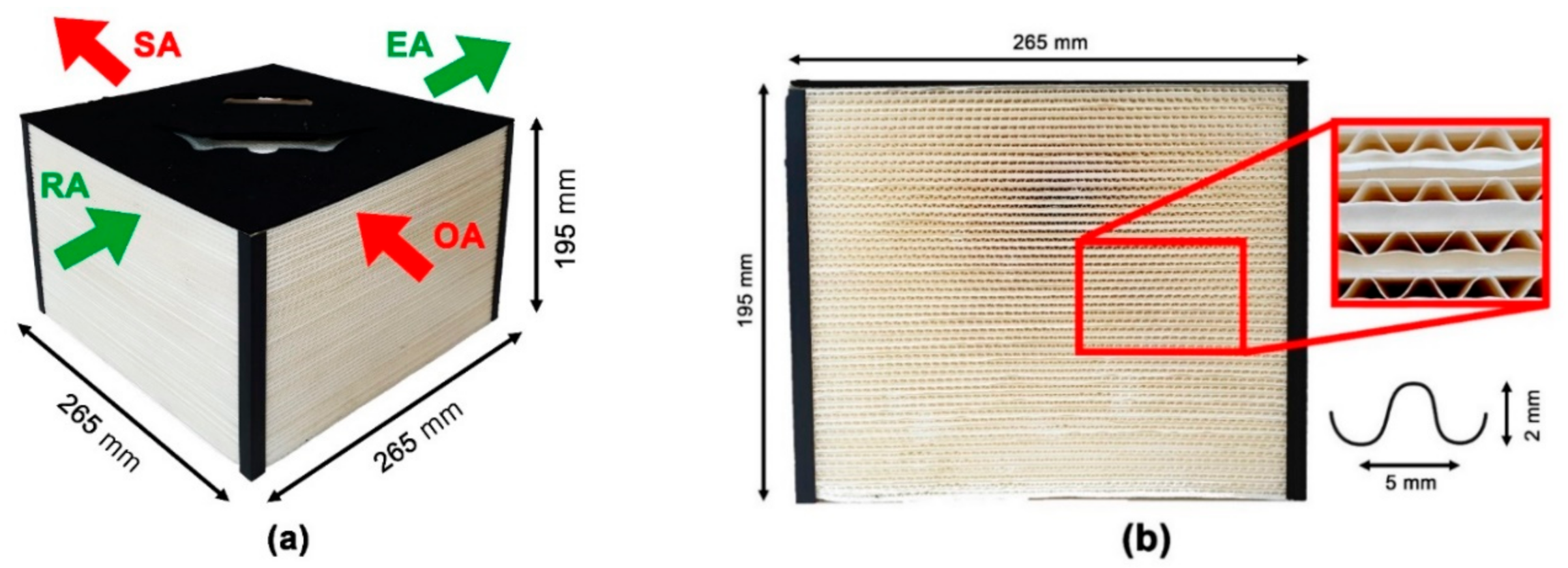
2.1. Experimental Setup

Figure 1 shows a schematic of the experimental setup used to measure the quantity of condensation and removal in heat recovery ventilators. A heat recovery ventilator was installed in a two-room air calorimeter that satisfied the ANSI/ASHRAE standard 37–1978 requirements [20]. The indoor and outdoor air temperatures and humidity conditions were controlled in the two rooms. The room with the heat recovery ventilator had an indoor air temperature and humidity similar to those of an actual living space. There were two air paths crossing the heat recovery ventilator: the OA path and return air (RA) path. Two Sirocco fans with inverters, installed at the exits of the SA and EA, respectively, were used to control the airflow rate. When driving the heat purge, a 1.6 kW heater installed at the RA inlet was used to increase the temperature of the purged air.
In the heat recovery ventilator, as shown in Figure 2, the heat exchanger element with a width of 265 mm, depth of 265 mm, and height of 195 mm was made of a heat recovery paper. The heat recovery paper restricts air transfer between the two channels while allowing heat and moisture exchange between them. The temperature, humidity, and pressure of the OA, SA, RA, and EA were measured using an resistance temperature detector (RTD), hygrometer, and digital pressure transducer, respectively. The pressure difference across the heat exchanger element was measured using a digital differential pressure transducer. In addition, the airflow rate was measured using a vortex flowmeter. Table 1 shows the specifications and accuracies of all the measuring devices.

2.2. Test Procedure

The experiment was conducted under the experimental conditions of KS B 6879 2017 [21]. As listed in Table 2, the quantities of condensation and removal in the heat recovery ventilator were measured under heating and cooling conditions. In the cooling condition, the indoor dry and wet bulb temperatures were maintained at 24 and 17 °C, respectively, whereas the outdoor dry and wet bulb temperatures were maintained at 35 and 24 °C, respectively. In the heating condition, the indoor dry and wet bulb temperatures were maintained at 22 and 13.9 °C, respectively, whereas the outdoor dry bulb temperature was maintained at −5 °C.
The designed air volume of the heat recovery ventilator was calculated using Equation (1).
V = A × H × ηv
where V is the effective ventilation volume with a unit of m3, A is the area, H is the height, and ηv is the ventilation space effectiveness. The area and height of 59 m2 and 2.4 m, respectively, correspond to the exclusive working space for multi-unit dwellings in Korea. The effective ventilation space was selected as 70%, excluding the volume of the furniture, kitchenware, and ventilation with separate facilities such as bathrooms and kitchens.
The ventilation interval was determined to be two hours according to Korean standards for facilities in buildings [22]; therefore, the designed ventilation rate was determined to be 50 CMH using Equation (2). In addition, as given in Equation (3), the condensate removal rate with a unit of g s–1 was calculated using the absolute humidity, airflow rate, and air density.
Designed ventilation rate = V × 0.5
Condensation removal rate = Q × ρ × ΔAH
where Q is the airflow rate with a unit of m3 s−1, ρ is the air density, and AH is the absolute humidity.
Table 3 lists the total uncertainties of the measured parameters from the sensors. The total uncertainties of the temperature and relative humidity at each point were in the ranges of ±0.36–1.14 °C and ±2.7–5.3%, respectively. The total uncertainties of the airflow rate ranged from ±8–10 m3 h−1 and the total uncertainty of the averaged condensation amount was ±4.26%. Since all the measured parameters had reasonably low uncertainties, the experiments can be considered reliable.

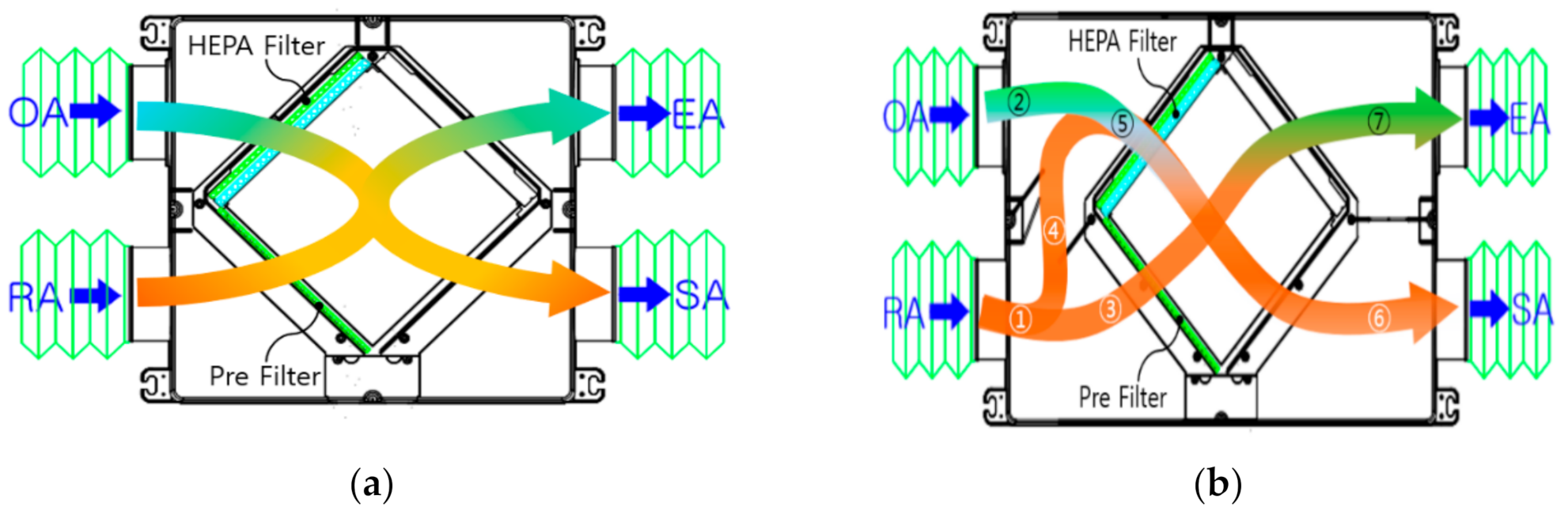
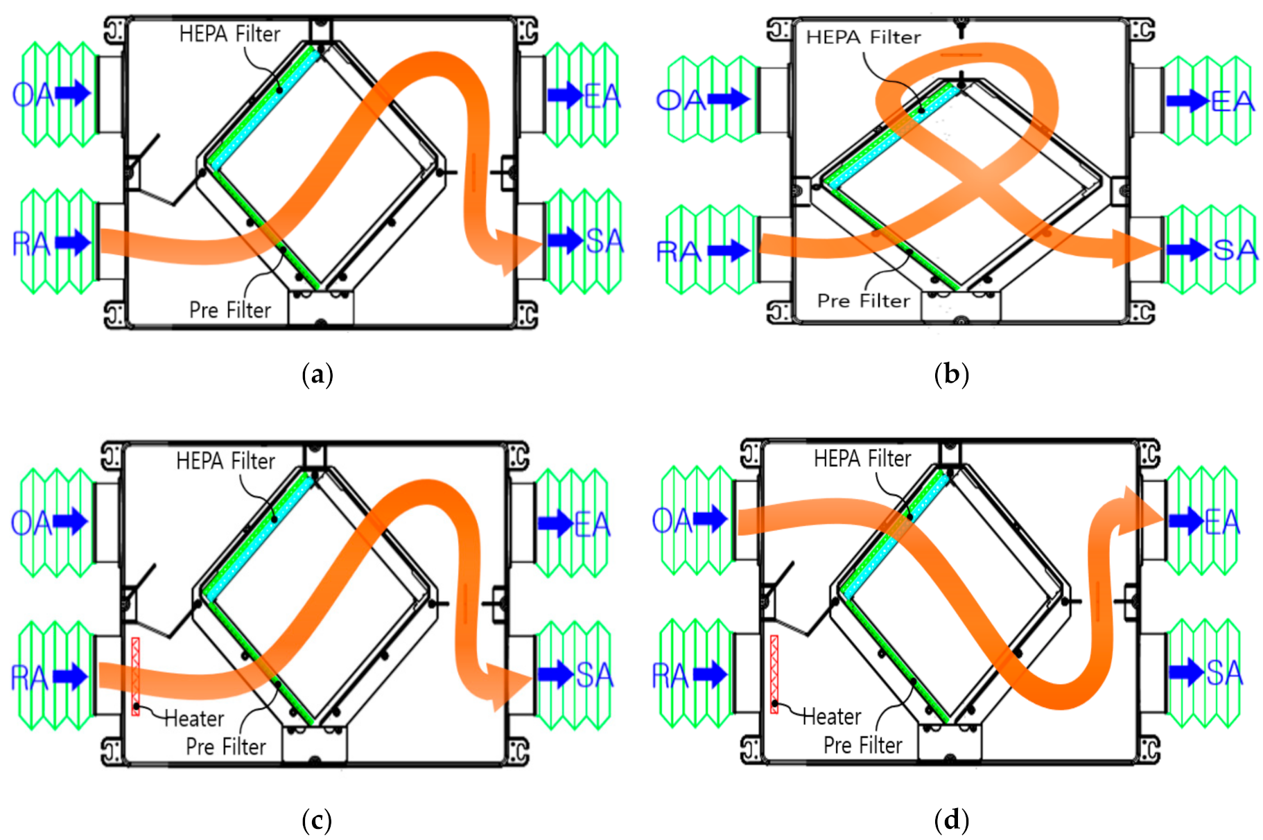
2.3. Proposed Ventilation and Purge Methods

Figure 3 shows two ventilation methods employed in the heat recovery ventilator. In the conventional method, as shown in Figure 3a, the RA passes through the heat exchanger element, discharging as the EA, whereas the cold OA is supplied to the indoors as the SA after passing through the heat exchanger element. In summer, the cold RA exchanges heat with the warm OA passing through the same flow path; the air is supplied to the indoor and subsequently discharged to the outdoor. In the mixed ventilation method, as shown in Figure 3b, the OA is mixed with a portion of the RA, which leads to an increase in the temperature. The temperature of the mixed OA is then increased to an above-zero value through heat exchange with the EA, thereby reducing the amount of condensation.
Figure 4 shows the proposed purge methods used to remove condensation by circulating the RA. The proposed purge methods include (a) normal purge, (b) circulation purge, (c) heat purge, and (d) outward purge. As shown in Figure 4a, the normal purge method is used to remove the accumulated condensation by directly passing the heat exchanger element and then, the RA is supplied indoors without being discharged to the outside. In the circulation purge method, as shown in Figure 4b, the RA passes the heat exchanger element and then reenters it through the OA flow path, which has a high efficiency particulate air (HEPA) filter. The HEPA filter acts as an indoor air purifier. However, if condensation is accumulated in the HEPA filter without being completely removed, the performance of the heat recovery ventilator can decrease. In the heat purge method, as shown in Figure 4c, a heater installed at the RA inlet provides heat to the RA, which can remove condensation instantly with minimum energy loss owing to the limited operation of the heater under the purge condition. Conventionally, condensation has been reduced by decreasing the temperature difference between the OA and RA by using a heater on the OA side; however, this can decrease the total heat transfer performance and increase total energy consumption. As shown in Figure 4d, the outward purge method is used to remove condensation in the summer condition. The condensation accumulated in the heat exchanger is removed by the OA with high temperature and the OA is then discharged to the outdoor to prevent any discomfort from the hot and humid air entering into the indoor area.

3. Results and Discussion

3.1. Performance Comparison for Proposed Ventilation and Purge Methods

As listed in Table 4, the performance of heat recovery ventilators with the three ventilation and purge methods were measured and compared. Cases 1–3 employed a heat purge with conventional ventilation, circulation purge with conventional ventilation, and heat purge with mixed ventilation, respectively. Figure 5a shows the quantity of condensation for Case 1 with a ventilation duration of 2 h at different outdoor temperatures from −5 to 35 °C. The indoor temperatures were maintained at 22 °C for winter, and the OA air flow rate was 50 CMH. As the outdoor temperature increased, the cumulative quantity of condensate for 2 h decreased owing to the decrease in the temperature difference between the OA and RA. In addition, as shown in Figure 5b, the quantity of condensate for Case 1 increased linearly with time owing to the proportional accumulation of condensation. Furthermore, as the outdoor temperature increased, the quantity of condensate decreased owing to the decrease in the temperature difference between the OA and RA.
Figure 6 shows the quantity of condensate in the heat recovery ventilator for Cases 1 to 3 at an indoor temperature of 22 °C and an outdoor temperature of −5 °C with an OA airflow rate of 50 CMH. As shown in Figure 6a, the quantity of condensation for all cases increased linearly with time. Because Cases 1 and 2 used the same ventilation method, the trends in the quantity of condensate were identical. However, Case 3 showed a lower amount of condensation than Case 1 at a given time owing to the benefit of the mixed ventilation method. In addition, the difference in the quantity of condensation between Case 1 and Case 3 increased with time owing to the accumulated benefits of the mixed ventilation method. As shown in Figure 6b, after ventilation for 30 min, 1 h, and 2 h, the cumulative condensation quantities for Cases 1 and 2 were 8.4, 16.1, and 30.8 g, whereas those of Case 3 were 6.1, 11.5, and 21.27 g, respectively. Accordingly, after ventilation operations of 30 min, 1 h, and 2 h, the cumulative amounts of condensation for Case 3 were 27.4%, 28.6%, and 30.9%, respectively; these amounts are lower than those for Cases 1 and 2. The decrease in the quantity of condensation for Case 3 was attributed to the increase in temperature at the OA heat exchanger inlet above zero owing to the combination of the inside air and OA.
Figure 7 shows the amount of condensation removal over time during a purge for Cases 1 to 3 at indoor and outdoor temperatures of 22 °C and −5 °C, respectively, with an OA airflow rate of 50 CMH. The purge operation was initiated after 2 h of ventilation. As shown in Figure 7a, for Cases 1 and 2, the amount of condensation removal increased rapidly and reached a maximum value of 30.8 g after approximately 50 min and 1 h of purge operations, respectively. The maximum quantity of condensation removal for Cases 1 and 2 corresponded to the cumulative condensation quantity during a ventilation duration of 2 h, as shown in Figure 6b. For Case 3, the maximum condensation removal of 21.27 g was observed at 30 min of the purge operation owing to the heat exchange using the mixed ventilation method. Accordingly, the purge time for Case 3 was significantly shorter than that for Cases 1 and 2. Furthermore, the purge time for Case 1 (heat purge) was 10 min shorter than that for Case 2 (circulation purge) owing to the increase in the vaporization of the condensation with a higher air temperature in the heat purge method. Overall, Case 3 (heat purge with mixed ventilation) showed the most preferable performance in terms of the condensation amount and purge time. In addition, as shown in Figure 7b, the condensation removal rate was substantially higher at the early stage of purge operation, and then decreased sharply to zero owing to a rapid decrease in the cumulative quantity of condensation at the beginning.

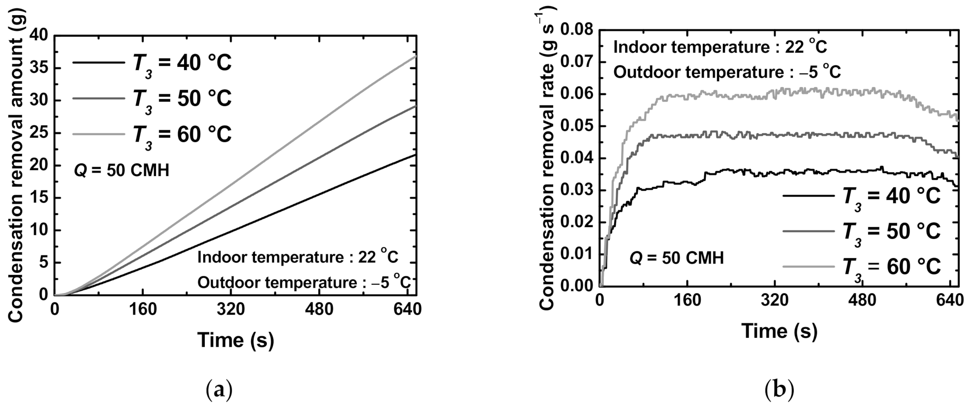
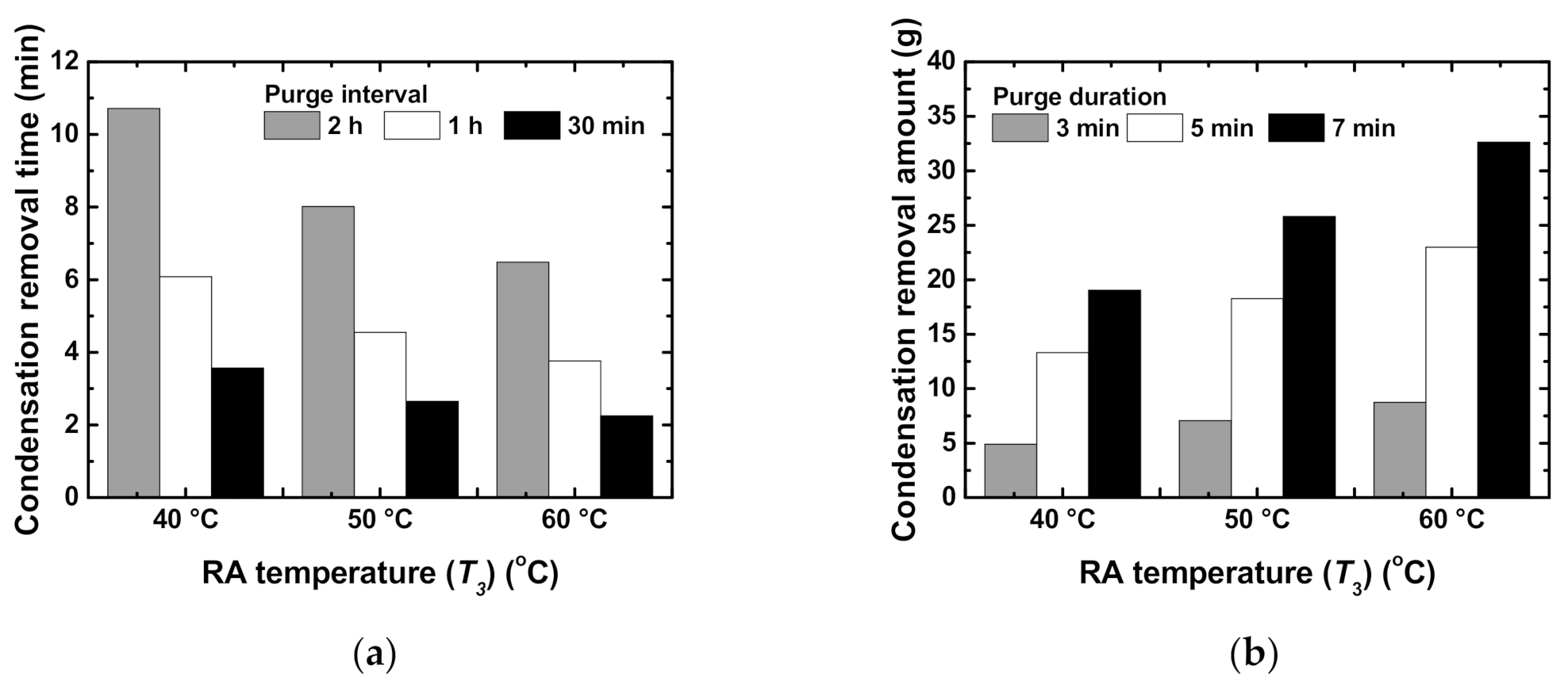
3.2. Effects of Operating Parameters for Case 3

Further investigation for Case 3 was conducted under varying operating conditions. Figure 8 shows the amount of condensation removal for Case 3 based on the purge air flow rate at an indoor temperature of 22 °C and an outdoor temperature of 5 °C with an RA temperature (T3) of 40 °C. The purge air flow rate was increased from 50 to 100 CMH, and the purge operation was initiated after 2 h of ventilation. Generally, it is effective to purge briefly either during or after a ventilation operation. Furthermore, the increase in the airflow rate during the purge can decrease the time taken to remove condensation. As shown in Figure 8a, the purge time taken to remove condensation decreased from 30 to 18 min with an increase in the purge air flow rate from 50 to 100 CMH owing to the increase in the forced convective heat transfer rate. Furthermore, as shown in Figure 8b, the peak condensation removal rate, which was observed during the early stage of the purge operation, increased substantially with the increase in the purge air flow rate, resulting in a decrease in the purge time. Moreover, the gradient of the condensation removal rate was the steepest at the purge air flow rate of 100 CMH owing to the highest mass transfer from condensation to air.
Figure 9 shows the effects of the RA temperature (T3) on the quantity of condensation removal for Case 3 at the purge air flow rate of 50 CMH. For Case 3, the heater at the RA inlet operated during the purge operation to remove the condensate on the heat exchanger element. Generally, a higher heater power enables a greater amount of condensation removal in a shorter time; however, excessively high temperatures should be avoided to prevent potential deformation of the heat recovery ventilator. Accordingly, in this study, the RA temperatures were set as 40, 50, and 60 °C, respectively. As shown in Figure 9a, the condensation removal rate increased with an increase in the RA temperature owing to the increase in the saturated evaporation of condensation. Furthermore, the effects of the RA temperature increased with the purge time. As shown in Figure 9b, the condensation removal rate increased rapidly at the early stage and then approached a constant value. Furthermore, as the RA temperature increased, the condensation removal rate increased steadily owing to the accelerated evaporation of condensation.
Figure 10a shows the time taken to remove the condensation for Case 3 according to the purge interval at various RA temperatures. For all purge intervals, the time taken to remove condensation decreased as the RA temperature increased from 40 to 60 °C, owing to the accelerated evaporation of condensation. Furthermore, for a given RA temperature, the condensation removal time decreased with a decrease in the purge interval owing to the reduced accumulative condensation. Figure 10b presents the condensation removal amount for Case 3 according to the purge duration at various RA temperatures. For all purge durations, the amount of condensation removal increased linearly with an increase in the RA temperature. Furthermore, for a given RA temperature, as the purge duration increased, the amount of condensation removal increased. In summary, to remove condensation, it was preferable to increase the RA temperature and purge duration, and to decrease the purge interval.

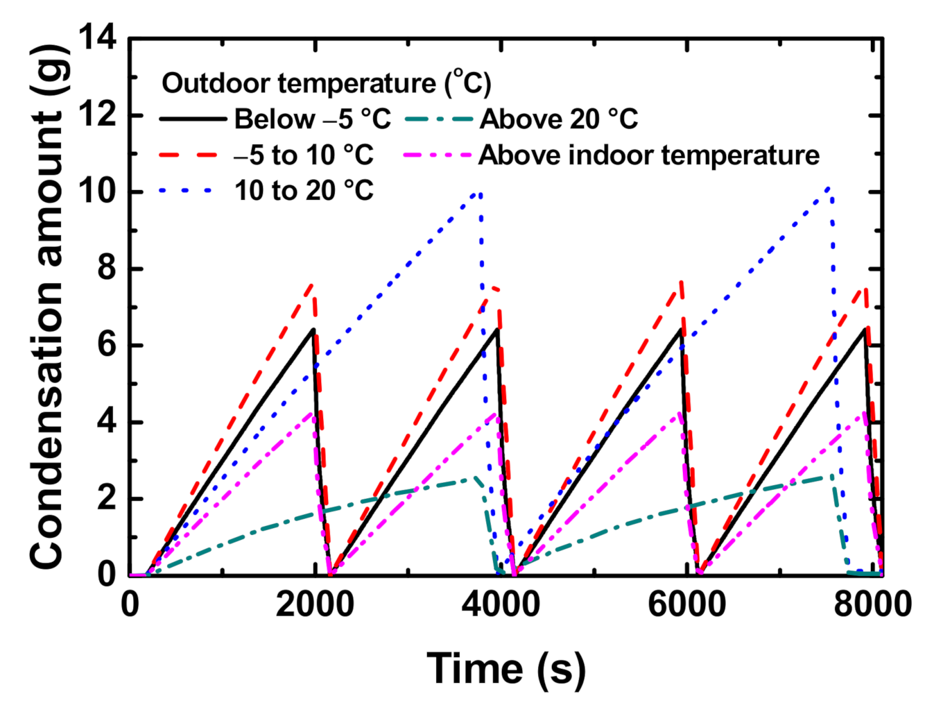
3.3. Optimum Ventilation and Purge Strategies

For Case 3, the optimum purge duration and RA temperature were determined to be 3 min and 60 °C, respectively, for maximum condensation removal performance. Even though a higher airflow rate results in a better condensation removal performance, it is more practical to set the purge air flow rate as the airflow rate used for ventilation; otherwise, the use of a larger fan will increase the initial cost of the heat recovery ventilator. Accordingly, the optimum purge air flow rate was determined to be 50 CMH, which is the airflow rate for ventilation in this study. Furthermore, separate pre-, mid-, and post-purges with a purge duration of 3 min are recommended to reduce the total purge time. The optimum purge interval for Case 3 at an indoor temperature of 22 °C and an outdoor temperature of 5 °C was 30 min. However, to achieve effective operation, the purge interval needs to be determined according to the outdoor temperature.
As listed in Table 5, the optimum ventilation and purge strategies are proposed according to the outdoor temperature. When the outdoor temperature is below −5 °C, mixed ventilation with the heat purge is recommended with a purge interval of 30 min owing to a large amount of condensation in this condition. When the outdoor temperature is in the range of −5 to 10 °C, conventional ventilation with a heat purge is recommended with a purge interval of 30 min. When the outdoor temperature is in the range of 10–20 °C, conventional ventilation with a heat purge is recommended with a purge interval of 60 min owing to the small amount of condensation. When the outdoor temperature exceeds 20 °C, conventional ventilation with the normal purge is recommended with a purge interval of 60 min because condensation hardly occurs in this condition. When the outdoor temperature is above the indoor temperature, conventional ventilation with the outward purge is recommended with a purge interval of 30 min.
Figure 11 shows the amount of condensation over time when the proposed optimum ventilation and purge strategies are used in the heat recovery ventilator. As the outdoor temperature increased, the rate of increase in the quantity of condensation over time decreased except for when the outdoor temperature was below −5 °C, owing to the use of the mixed ventilation method. For the outdoor temperatures from 10 to 20 °C and above 20 °C, the purge interval was changed to 1 h instead of 30 min owing to the small amount of condensation. Overall, based on the use of the proposed optimum strategies, the amount of condensation in the heat recovery ventilator was controlled to below 10 g during the entire operation time, which yielded a substantial reduction in the amount of condensation compared with that without the purge. When compared to Case 1, which uses the conventional ventilation and heat purge with a purge interval of 2 h, the proposed purge strategies showed at least a 33% up to 80% of condensation reduction in the range of the outdoor temperature from 20 to −5 °C. Accordingly, the optimum strategies proposed in this study can effectively reduce the growth of microorganisms and fungi and also increase the heat recovery efficiency of the heat recovery ventilator by significantly decreasing the amount of condensation. However, further study is necessary to reflect various outdoor humidity conditions and to conduct overall energy analysis on the ventilator with electric heaters for the heat purge.

4. Conclusions

Several purge and ventilation methods have been proposed to reduce condensation and improve condensation removal performance in a heat recovery ventilator. The experiments were conducted for three proposed ventilation and purge methods. The condensation amount decreased with a reduction in the ventilation duration owing to the decreased overall condensation. The proposed Case 3 showed the most preferable performance among the three proposed cases in terms of the quantity of condensation. For Case 3, the condensation removal increased with an increase in the purge air flow rate and RA temperature owing to the enhanced heat and mass transfer of condensate water in the heat exchanger element. In addition, as the purge interval decreased, the time taken to remove condensation decreased owing to the decreased accumulative condensation. According to the experimental results, the optimum ventilation and purge strategies were proposed as a function of the outdoor temperature. The heat recovery ventilator with the proposed ventilation and purge strategies exhibited a substantial reduction in the quantity of condensation compared with that without the purge. When compared to Case 1, the proposed strategies reduced 33 to 80% of the amount of condensation accumulated in the heat recovery element, which could lead to a significant reduction in the growth of microorganisms and fungi as well as to an enhanced heat recovery efficiency. This study provides useful information to understand the operating characteristics of a heat recovery ventilator and to determine optimum operating ventilation and purge strategies. However, further study is necessary to reflect various outdoor humidity conditions and to conduct overall energy analysis on the heat recovery ventilator with electric heaters for the heat purge to overcome the limitations of this study.

Author Contributions

Conceptualization, K.P. and Y.K.; methodology, K.P.; formal analysis, K.P. and D.L.; investigation, K.P. and Y.K.; data curation, K.P. and H.J.C.; writing—original draft preparation, K.P.; writing—review and editing, D.L. and Y.K.; supervision, Y.K.; project administration, Y.K.; funding acquisition, Y.K. All authors have read and agreed to the published version of the manuscript.

Funding

This research was supported by the Korea Agency for Infrastructure Technology Advancement (KAIA) grant funded by the Ministry of Land, Infrastructure and Transport (Grant 20HSCT-B157909-01).

Conflicts of Interest

The authors declare no conflict of interest. The funders had no role in the design of the study; in the collection, analyses, or interpretation of data; in the writing of the manuscript, or in the decision to publish the results.

References

  1. Choi, Y.; Song, D. An Evaluation on energy recovery performance of the ventilation system in multi-residential building by field measurement. Korean J. Air-Cond. Refrig. Eng. 2017, 29, 68–73. [Google Scholar]
  2. Lee, E.; Song, K.; Oh, W.; Cho, J.; Kim, N. Performance of an enthalpy exchanger at different humidity condition. In Proceedings of the KSME Conference, Seoul, Korea, 23–24 April 2009; pp. 1595–1599. [Google Scholar]
  3. Chun, C.; Kim, G.; Lee, J.; Kim, S. A Study on the performance evaluation of the hybrid ventilation system for small apartment houses. Korean J. Air-Cond. Refrig. Eng. 2008, 20, 696–701. [Google Scholar]
  4. Kang, I.; Shin, C.; Jung, J.; Park, J.; Lee, H.; Park, T. A CFD simulation for HVAC system efficiency of humidity exchanger. In Proceedings of the SAREK Conference, Seoul, Korea, November 2015; pp. 170–173. [Google Scholar]
  5. Lim, T.; Jeon, B.; Ahn, Y. Experimental analyses on the effects of heat transfer efficiency of a heat recovery ventilation system according to the air flow ratio between supply and exhaust flows. In Proceedings of the KIAEBS Conference, Seongnam, Korea, March 2011; pp. 157–160. [Google Scholar]
  6. Kim, K.; Park, J.; Rhee, E. An experimental study on the ventilation effectiveness of ventilation system in apartment houses. In Proceedings of the KSES Conference, Seoul, Korea, November 2003; pp. 170–175. [Google Scholar]
  7. Kim, K.; Rhee, E. A study on the ventilation effectiveness of mechanical ventilation system in apartment buildings. In Proceedings of the SAREK Conference, Seoul, Korea, November 2003; pp. 537–542. [Google Scholar]
  8. Pashchenko, D. Thermochemical recuperation by ethanol steam reforming: Thermodynamic analysis and heat balance. Int. J. Hydrog. Energy 2019, 44, 30865–30875. [Google Scholar] [CrossRef]
  9. Pashchenko, D.; Gnutikova, M.; Karpilov, I. Comparison study of thermochemical waste-heat recuperation by steam reforming of liquid biofuels. Int. J. Hydrog. Energy 2020, 7, 4174–4181. [Google Scholar] [CrossRef]
  10. Yee, J.; Kim, S. A study on an energy-efficient outdoor air supply operation control method of apartment heat recovery ventilation system. J. Archit. Inst. Korea 2009, 25, 295–302. [Google Scholar]
  11. Jeong, J.; Chae, Y. Performance evaluation of plate-type enthalpy exchanger for residential buildings. In Proceedings of the SAREK Conference, Pyeongchang, Korea, 22–24 June 2016; pp. 621–624. [Google Scholar]
  12. Kim, G.; Chun, C.; Kim, S. Evaluation of energy performance according to the ventilation system in small apartment house. In Proceedings of the SAREK Conference, Pyeongchang, Korea, June 2015; pp. 178–179. [Google Scholar]
  13. Kim, H.; Park, J. Effects of ventilation system operation on annual energy consumption in apartments. In Proceedings of the JAIK Conference, Chuncheon, Korea, October 2009; pp. 757–760. [Google Scholar]
  14. Park, J.; Kim, J.; Jeong, J.; Song, D. An analysis of energy-saving effect for ERV (Energy Recovery Vehicle) with economizer control. In Proceedings of the JAIK Conference, Chuncheon, Korea, October 2009; pp. 737–740. [Google Scholar]
  15. TRNSYS, University of Wisconsin-Madison, Solar Energy Laboratory: Madison, WI, USA. 1975. Available online: https://sel.me.wisc.edu/trnsys/index.html (accessed on 22 November 2020).
  16. Kim, H.; Kim, J.; Park, J. Effects of ventilation system on energy consumption in apartments. In Proceedings of the KIAEBS Conference, Seoul, Korea, October 2009; pp. 170–173. [Google Scholar]
  17. Nam, H.; Bai, C.; Kwon, Y.; Kim, S.; Chu, E. A study on reducing condensation in winter operation of total heat exchanger. In Proceedings of the SAREK Conference, Pyeongchang, Korea, 6–8 July 2011; pp. 747–750. [Google Scholar]
  18. Kim, W.; Jeong, J. Determination of preheat coil capacity in an energy recovery ventilator considering the differences in sensible and latent effectiveness values. J. Korean Inst. Archit. Sustain. Environ. Build. Syst. 2017, 11, 197–202. [Google Scholar]
  19. Jeon, B.; Kim, J.; Lee, S.; Lee, Y.; Ahn, Y. A study on the dew condensation according to the operational conditions of heat-recovery ventilator. In Proceedings of the SAREK Conference, Seoul, Korea, November 2012; pp. 191–194. [Google Scholar]
  20. ANSI/ASHRAE. Method of Testing for Rating Unitary Air Conditioning and Heat Pump Equipment; American Society of Heating, Refrigerating and Air Conditioning Engineers: Peachtree Corners, GA, USA, 1978. [Google Scholar]
  21. Korean Standards. Heat Recovery Ventilation; KS B 6879; Korean Standards: Seoul, Korea, 2017. [Google Scholar]
  22. Ordinance of the Ministry of Land, Infrastructure and Transport, Korean Government. Rules on Equipment Standards for Buildings; Korean Government: Sejong, Korea, 2020.
Figure 1. Schematic of experimental setup.
Energies 13 06152 g001
Figure 2. Pictures of heat exchanger element: (a) flow configuration; (b) specific dimension of the heat exchanger element.
Energies 13 06152 g002
Figure 3. Ventilation methods: (a) conventional; (b) mixed ventilation.
Energies 13 06152 g003
Figure 4. Purge methods: (a) conventional; (b) circulation; (c) heat; (d) outward.
Energies 13 06152 g004
Figure 5. Results of 2 h operation for Case 1: (a) cumulative condensation quantity according to outdoor temperature; (b) condensation quantity over time.
Energies 13 06152 g005
Figure 6. Results of Cases 1–3: (a) condensation quantity over time; (b) cumulative condensation quantity for different ventilation durations.
Energies 13 06152 g006
Figure 7. Comparison of Cases 1–3: (a) condensation removal quantity; (b) condensation removal rate over time.
Energies 13 06152 g007
Figure 8. Result of Case 3 at various purge air flow rates: (a) condensation removal quantity; (b) condensation removal rate over time.
Energies 13 06152 g008
Figure 9. Result of Case 3 at various RA temperatures (T3): (a) condensation removal quantity; (b) condensation removal rate over time.
Energies 13 06152 g009
Figure 10. Result of Case 3 according to the RA temperature (T3): (a) time taken to remove condensation at various purge intervals; (b) condensation removal quantity at various purge durations.
Energies 13 06152 g010
Figure 11. Condensation quantity over time when the proposed optimum ventilation and purge strategies are applied for the heat recovery ventilator.
Energies 13 06152 g011
Table 1. Specifications and accuracies of measuring devices.
Measuring DevicesUnitRangeAccuracy
RTD°Cfrom −200 to 600±0.2 °C
Pressure transducerkPa0–490.33±1.23 kPa
Relative humidity sensor%0–100±2.0%
Volumetric flowmeterm3 h−10–800±8 m3 h−1
Differential pressure transducerkPafrom −29.42 to 29.42±38 Pa
Table 2. Test conditions.
ConditionIndoorOutdoorAirflow Rate
(CMH)
Dry Bulb (°C)Wet Bulb (°C)Dry Bulb (°C)Wet Bulb (°C)
Cooling24.017.03524.050
Heating22.013.9–5.0-50
Table 3. Total uncertainties of measured parameters.
Measured ParameterTotal Uncertainty
RA temperature (T1)±0.36 °C
SA temperature (T2)±0.48 °C
OA temperature (T3)±0.32 °C
EA temperature (T4)±1.14 °C
RA relative humidity (RH1)±2.7%
SA relative humidity (RH2)±3.8%
OA relative humidity (RH3)±3%
EA relative humidity (RH4)±5.3%
EA flow rate (Q1)±10 m3 h−1
SA flow rate (Q2)±8 m3 h−1
Averaged condensation quantity±4.26%
Table 4. Proposed cases for ventilation and purge methods.
Case numberVentilation MethodPurge Method
Case 1Conventional ventilationHeat purge
Case 2Conventional ventilationCirculation purge
Case 3Mixed ventilationHeat purge
Table 5. Optimum ventilation and purge strategies according to outdoor temperature.
Outdoor TemperatureVentilation MethodPurge IntervalPurge Method *
Below –5 °CMixed ventilation30 minHeat purge **
from –5 to 10 °CConventional ventilation30 minHeat purge **
10–20 °CConventional ventilation60 minHeat purge **
Above 20 °CConventional ventilation60 minNormal purge
Above indoor temperatureConventional ventilation30 minOutward purge
* Purge was separately conducted as pre-, mid-, and post-purges with a 3-min duration; ** RA temperature is maintained at 60 °C.
Publisher’s Note: MDPI stays neutral with regard to jurisdictional claims in published maps and institutional affiliations.

