Floating Offshore Renewable Energy Farms. A Life-Cycle Cost Analysis at Brindisi, Italy


Abstract
:1. Introduction
2. Structures Characteristic Data
2.1. Turbine Characteristic Data
2.2. Structural Characteristics of TLP and SB Platform
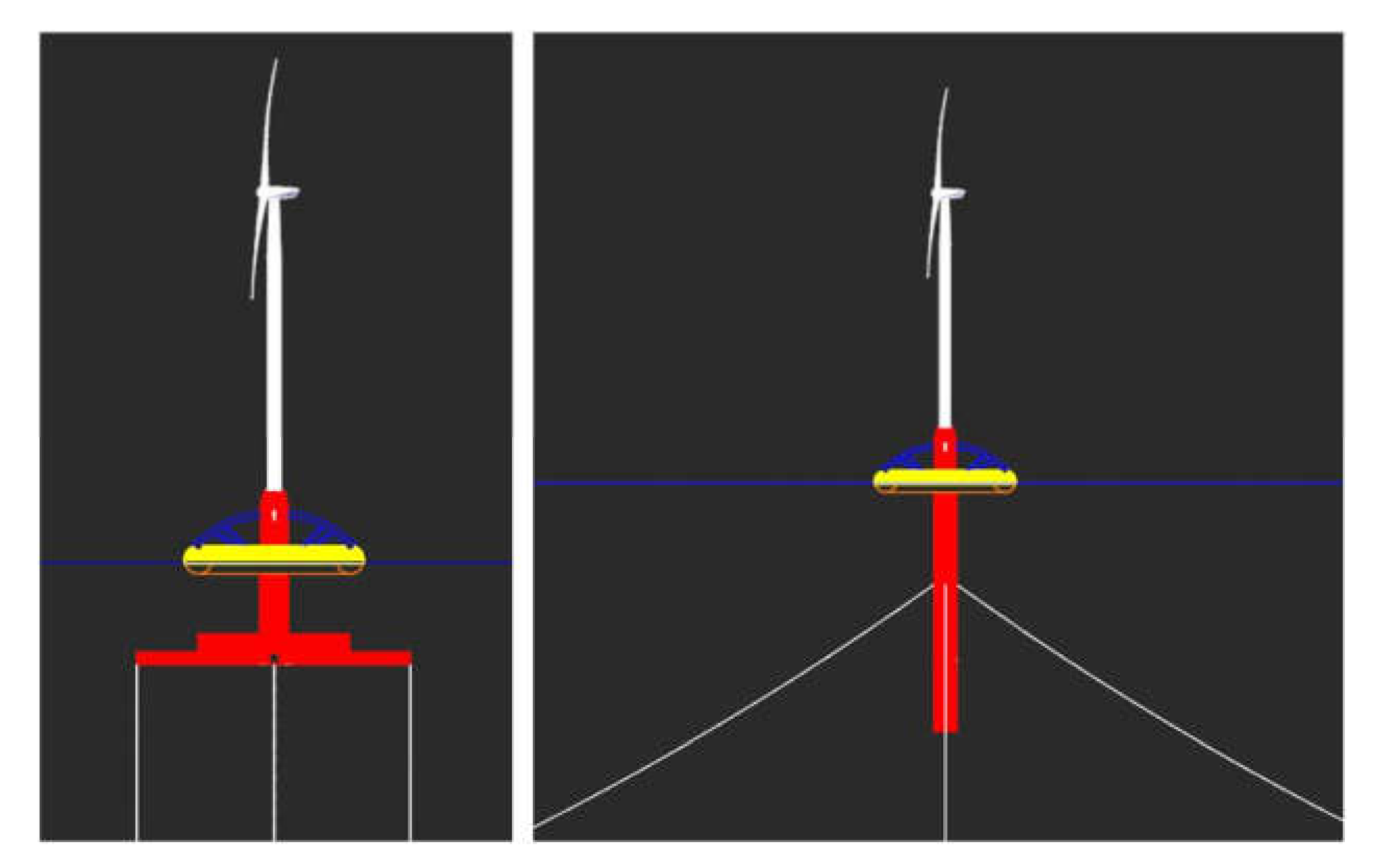
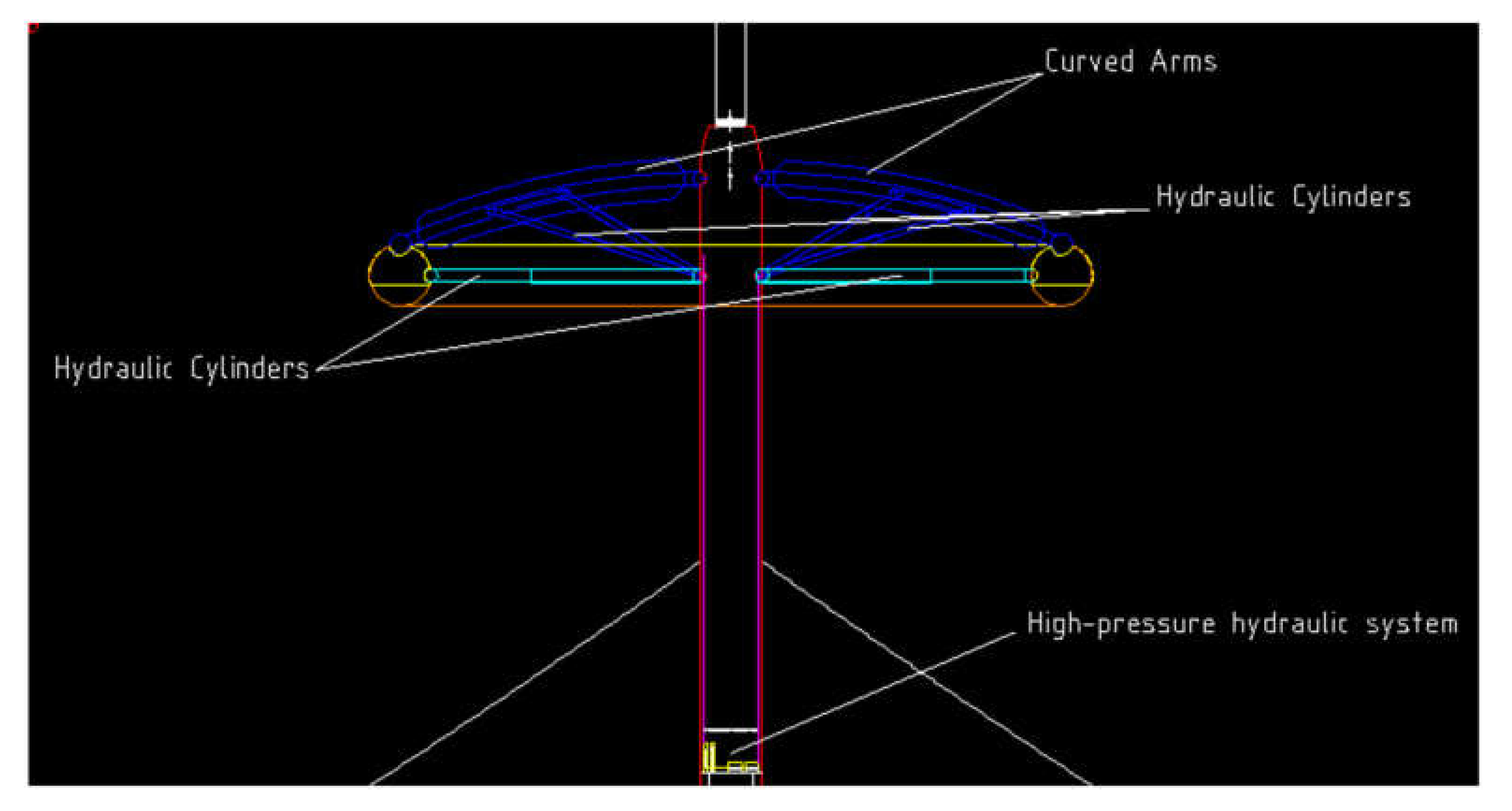
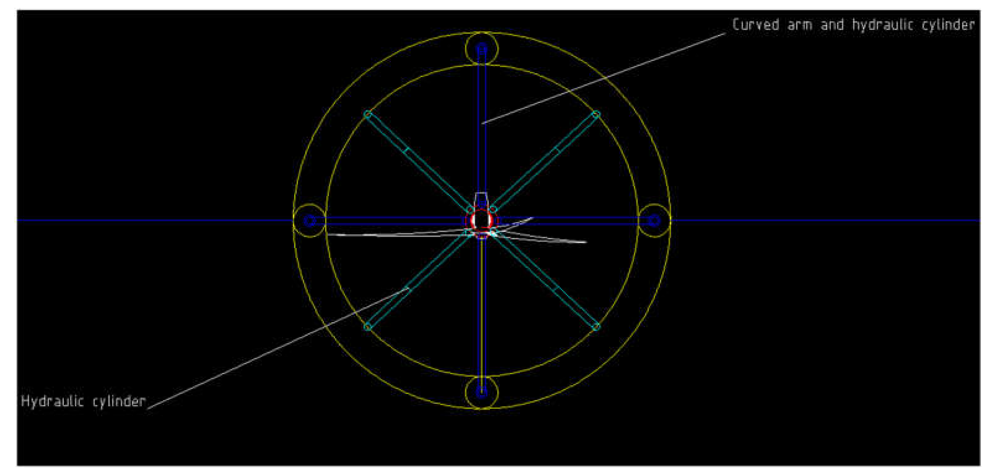
2.3. Description of HWWES and Structural Characteristics of WEC Device
- Four curved arms anchored by two 2D joints on one side to the SB or TLP platform and on the other to the upper part of the circular float. In the lower part of the arms are connected, in turn, four large hydraulic cylinders, which by means of two 2D joints are hooked on one side to the SB or TLP platform in a fixed manner and on the other with a mobile joint (sliding) to the lower part of the arms (Figure 2).
- 2.
- Four arms/large straight hydraulic cylinders anchored by two 2D joints on one side to the SB or TLP platform and, on the other, to the low internal part of the circular float (Figure 3).
- A closed circuit where the water inside is at high pressure
- A hydropneumatic accumulator
- A hyperbaric chamber
- A Pelton-type hydroelectric turbine
- A current generator
3. Method
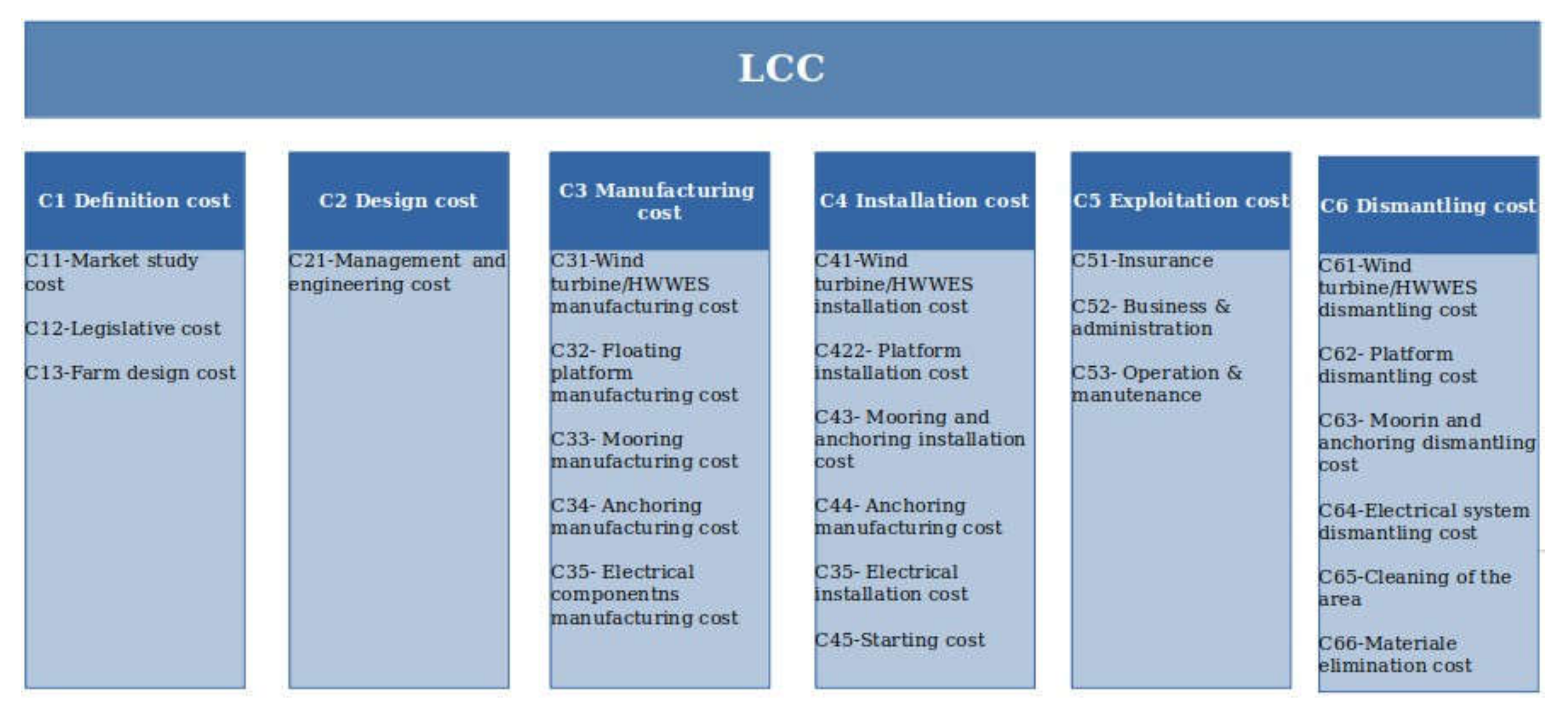
- ■
- Definition phase
- C11—Market study cost
- C12—Legislative factors cost
- C13—Farm design cost
- ■
- Design phase
- C21—Management and engineering cost
- ■
- Manufacturing phase
- C31—Wind turbine/HWWES manufacturing
- C32—Floating platforms manufacturing
- C33—Mooring manufacturing
- C34—Anchoring manufacturing
- C35—Electrical component manufacturing
- ■
- Installation phase
- C41—Wind turbine/HWWES installation cost
- C42—Platform installation cost
- C43—Mooring and anchoring installation cost
- C44—Electrical installation cost
- C45—Starting cost
- ■
- Exploitation phase
- C51—Insurance
- C52—Business and administration
- C53—Operation and maintenance
- ■
- Dismantling phase
- C61—Wind turbine/HWWEs dismantling cost
- C62—Platform dismantling cost
- C63—Mooring and anchoring dismantling cost
- C64—Electrical system dismantling cost
- C65—Cleaning of the area
- C66—Materials elimination cost
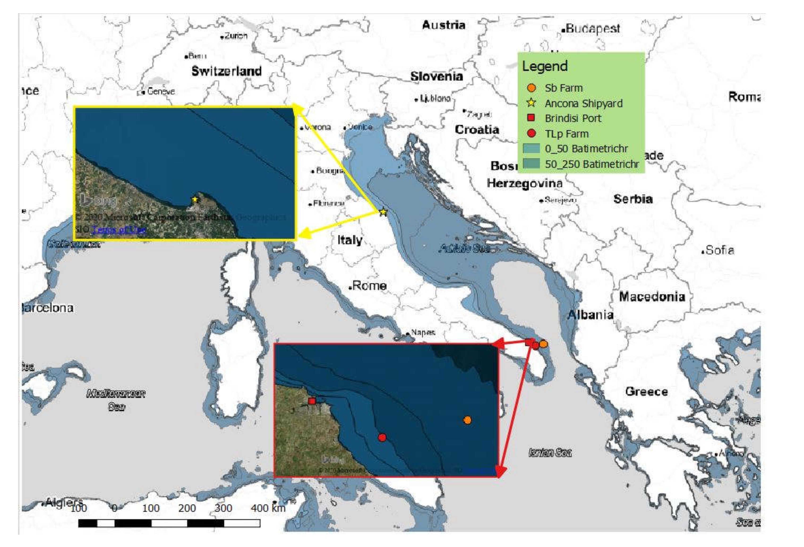
4. Case Study Area
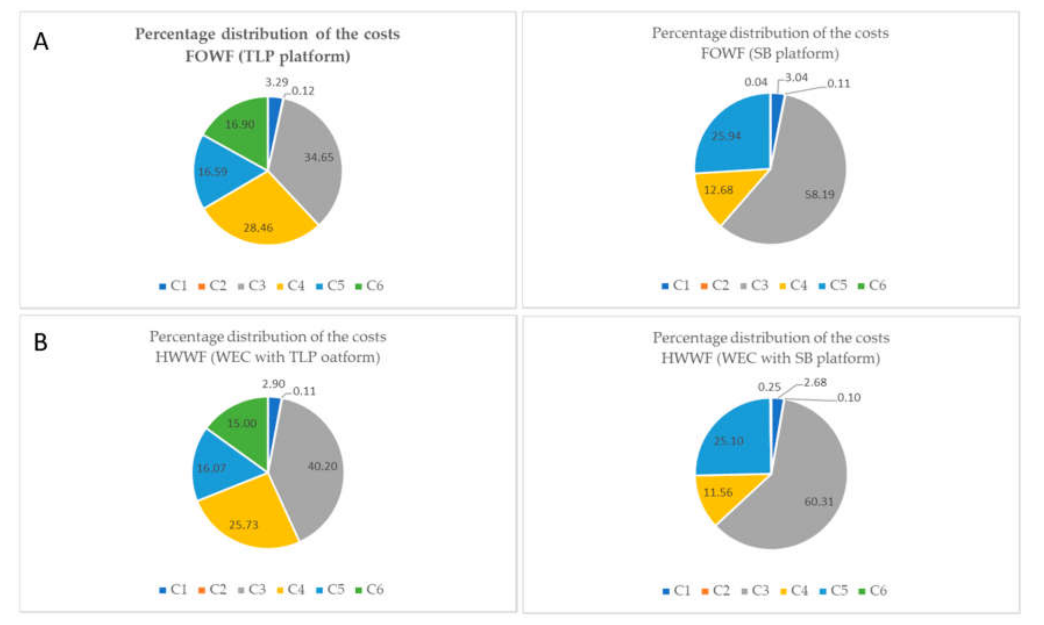
5. Results and Discussion
6. Conclusions
Author Contributions
Funding
Conflicts of Interest
Abbreviations
| LCC | Life-Cycle Cost |
| CBS | Cost Breakdown Structure |
| FOWF | Floating offshore wind farm |
| HWWF | Hybrid wind-wave farm |
| HWWES | Hybrid wind-wave energy system |
| WEC | Wave energy converter |
| TLP | Tension Leg Platform |
| SB | Spar Buoy platform |
| LCOE | Levelized Cost of Energy |
| SS | Semi-Submersible platform |
| FWT | Floating wind turbine |
| Bpto | Damping coefficient |
| Kpto | Spring coefficient |
| NWT/HWWES | Number of wind turbine/Number of hybrid wind-wave energy system |
| PWT/HWWES | Power of wind turbine/Power of hybrid wind-wave energy system |
| Cfsb | Cost of the preliminary feasibility study |
| CTax | Country’s taxes |
| Ces | Study cost related to energy resource availability and sea condition |
| Cgs | Study cost of the geotechnical characteristics of the seabed |
| Ceng | Unit cost of engineering phase |
| CMW | Cost of generator |
| Cpla_gen | Manufacturing cost of the floating platforms for generators |
| Csubstat | Manufacturing cost related to the floating platform of the substation |
| Psubstat | Number of floating platforms for the substation |
| CDM | Material costs |
| CDL | Direct labor cost |
| CA | Activity cost |
| B | Industrial profit |
| mp | Platform mass |
| S | Surface of the platforms |
| Cmo | Direct labor cost per hour |
| Csteel | Steel cost |
| wm | Moorings weight |
| lm | Moorings length |
| Cm | Mooring cost per Kg |
| Nml | Number of mooring lines for platform |
| Ncable | Number of electrical cables |
| Lcable | Length of electrical cables |
| Dcable | Diameter of electrical cables |
| Ccable | Cost in €/m of the electric cable |
| β | Correction coefficient |
| NT | Number transformer |
| CT | Cost of transformer |
| Csw | Cost of witchgear |
| Cgensh/po | Costs installation generator related to shipyard and/or port operations |
| Cgentrans | Transport costs for generator installation |
| Cgeninst | Costs installation generator |
| Cfpsh/po | Costs installation platforms related to shipyard and/or port operations |
| Cfptrans | Transport costs for installation floating platforms |
| Cfpinst | Costs installation of floating platforms |
| Cmaship | Ship costs for mooring and anchor installation |
| CmaDL | Labor direct for mooring and anchor installation |
| Cmapd | Cost of pumps and divers for mooring and anchor installation |
| Nanch | Number of anchors |
| Tmainst | Time for mooring and anchoring installation |
| Cinst_cable | Costs of installation of the electrical cables |
| Cinst_sub | Cost installing the substation |
| Cstart-up | Cost start-up |
| Nyfarm | Number of years of the life-cycle of the farm |
| Cadm | Costs administration farm |
| Clegal | Costs legal aspects |
| Cprev_maint | Preventive maintenance cost |
| Ccorr | Corrective cost |
| Cdism_WT/HWWES | Generator dismantling cost |
| Cdism_tras_WT/HWWES | Transport cost (generator dismantling) |
| Cdism_op | Operations at port (generator dismantling) |
| Cdism_plat_WT/HWWES | Platform dismantling cost |
| Cdism_trans_plat_WT/HWWES | Transport cost (platform dismantling) |
| Cdism_plat_op | Operations at port (platform dismantling) |
| Cmaship | Cost of the ship |
| Cmapd | Pump and diverse costs |
| Tdismant | Time for dismantling |
| Carea | Cost of cleaning the farm area |
| Ndline | Number of diameters for lines |
| DWT/HWWES | Generator diameter |
| NDWT/HWWES | Number of diameters between WT/HWWES, |
| Cproc_disp-mat | Cost of processing disposal materials |
| Ctransp_disp_mat | Transportation cost (disposal materials) |
| Celim | Elimination cost |
| E | Energy production (Mwh/year) |
| r | Discount rate (%) |
References
- GWEC, Global Wind Energy Concil. Global Offshore Wind Report 2020. Available online: https://gwec.net/global-offshore-wind-report-2020 (accessed on 1 September 2020).
- IRENA. Future of Wind—Deployment, Investment, Technology, Grid Integration and Socio-Economic Aspects; October 2019; ISBN 978-92-9260-155-3. Available online: https://www.irena.org/publications/2019/Oct/Future-of-wind (accessed on 20 August 2020).
- Viselli, A.M.; Goupee, A.J.; Dagher, H.J. Model test of a 1:8 scale floating wind turbine offshore in the Gulf of Maine. In Proceedings of the ASME 2014 33rd International Conference on Ocean, Offshore and Arctic Engineering OMAE2014, San Francisco, CA, USA, 8–13 June 2014. [Google Scholar]
- Zhang, S.; Ishihara, T. Hydrodynamic response of a Semi-Submersible floating offshore wind turbine: Numerical modelling and validation. In Proceedings of the 15th World Wind Energy Conference, Tokyo, Japan, 1 October–1 November 2016. [Google Scholar]
- Liu, Z.; Fan, Y.; Wang, W.; Qian, G. Numerical study of a Proposed Semi-Submersible Floating Platform with Different Numbers of Offset Columns Based on the DeeCWind Prototype for improving the Wave-Resistance Ability. Appl. Sci. 2019, 9, 1255. [Google Scholar] [CrossRef] [Green Version]
- Liu, Y.; Li, S.; Yi, Q.; Chen, D. Developments in semi-submersible floating foundations supporting wind turbine: A comprehensive review. Renew. Sustain. Energy Rev. 2016, 60, 433–449. [Google Scholar] [CrossRef]
- Nihei, Y.; Fujioka, H. Motion characteristics of a TLP type offshore wind turbine in waves and wind. In Proceedings of the 29th International Conference on Ocean, Offshore and Arctic Engineering, Shanghai, China, 6–11 June 2010. [Google Scholar]
- Wehemeyer, C.; Ferri, F.; Skourup, J.; Freegard, P.B. Experimental Study of an Offshore Wind Turbine TLP in ULS Conditions. In Proceedings of the Twenty-third (2013) International Offshore and Polar Engineering, Anchorage, AK, USA, 30 June–5 July 2013. [Google Scholar]
- Pegalajar-Jurado, A.; Bredmose, H.; Borg, M. Multi-level Offshore hydrodynamic modelling of a scaled 10MW TLP wind turbine. Energy Procedia 2016, 94, 124–132. [Google Scholar] [CrossRef] [Green Version]
- Oguz, E.; Clelland, D.; Day, A.H.; Incecik, A.; Lopez, J.A.; Sanchez, G.; Almeria, G.G. Experimental and numerical analysis of a TLP floating offshore wind turbine. Ocean Eng. 2018, 147, 591–605. [Google Scholar] [CrossRef] [Green Version]
- Xu, X.; Srinil, N. Dynamic response analysis of spar-type floating wind turbines and mooring lines with uncoupled vs coupled models. In Proceedings of the ASME 2015 34th International Conference on Ocean, Offshore and Arctic Engineering OMAE2015, St. John’s, NF, Canada, 31 May–5 June 2015. [Google Scholar]
- Driscoll, F.; Jonkman, J.; Robertson, A.; Sirnivas, S.; Skaare, B.; Nielsen, F.G. Validation of a FAST model of the statoil-hywind demo floating wind turbine. Energy Procedia 2016, 94, 3–19. [Google Scholar] [CrossRef] [Green Version]
- Tomasicchio, G.R.; Avossa, A.M.; Riefolo, L.; Ricciardelli, F.; Musci, E.; D’Alessandro, F.; Vicinanza, D. Dynamic Modelling of a Spar Buoy Wind Turbine. In Proceedings of the ASME 2017 36th International Conference on Ocean, Offshore and Arctic Engineering, Volume 10: Ocean Renewable Energy, Trondheim, Norway, 25–30 June 2017. [Google Scholar]
- Riefolo, L.; del Jesus, F.; García, R.G.; Tomasicchio, G.R.; Pantusa, D. Wind/Wave Misalignment Effects on Mooring Line Tensions for a Spar Buoy Wind Turbine. In Proceedings of the ASME 2018 37th International Conference on Ocean, Offshore and Arctic Engineering, Madrid, Spain, 17–22 June 2018. [Google Scholar]
- Tomasicchio, G.R.; D’Alessandro, F.; Avossa, A.M.; Riefolo, L.; Musci, E.; Ricciardelli, F.; Vicinanza, D. Experimental modelling of the dynamic behaviour of a spar buoy wind turbine. Renew Energy 2018, 127, 412–432. [Google Scholar] [CrossRef]
- Stewart, G.; Muskulus, M. A Review and Comparison of Floating Offshore Wind Turbine Model Experiments. Energ. Procedia 2016, 94, 227–231. [Google Scholar] [CrossRef] [Green Version]
- Leimeister, M.; Kolios, A.; Coll, M. Critical review of floating support structures for offshore wind farm deployment. J. Phys. Conf. Ser. 2018, 1104, 012207. [Google Scholar] [CrossRef]
- Salic, T.; Charpentier, J.F.; Benbouzid, M.; Le Bolluec, M. Control Strategies for Floating Offshore Wind Turbine: Challenges and Trends. Electronics 2019, 8, 1185. [Google Scholar] [CrossRef] [Green Version]
- Antonio, F.D.O. Wave energy utilization: A review of technologies. Renew. Sustain. Energy Rev. 2010, 14, 899–918. [Google Scholar] [CrossRef]
- López, I.; Andreu, J.; Ceballos, S.; de Alegría, I.M.; Kortabarria, I. Review of wave energy technologies and the necessary power-equipment. Renew. Sust. Energ. Rev. 2013, 27, 413–434. [Google Scholar] [CrossRef]
- Titah-Benbouzid, H.; Benbouzid, M. An Up-to-Date Technologies Review and Evaluation of Wave Energy Converters. Int. Rev. Electr. Eng. 2015, 10, 52–61. [Google Scholar] [CrossRef]
- Rusu, E.; Onea, F. A review of the technologies for wave energy extraction. Clean Energy 2018, 2, 10–19. [Google Scholar] [CrossRef] [Green Version]
- Perez-Collazo, C.; Jakobsen, M.M.; Buckland, H.; Fernandez Chozas, J. Synergiesfor a wave–wind energy concept. In Proceedings of the European Offshore Wind Energy Conference; EWEA: Frankfurt, Germany, 2013; pp. 1–10. [Google Scholar]
- Perez-Collazo, C.; Greaves, D.; Iglesias, G. A Novel Hybrid Wind-Wave Energy Converter for Jacket-Frame Substructures. Energies 2018, 11, 637. [Google Scholar] [CrossRef] [Green Version]
- Bachynski, E.E.; Moan, T. Point absorber design for a combined wind and wave energy converter on a tension-leg support structure. In Proceedings of the 32th International Conference on Ocean, Offshore and Arctic Engineering OMAE, Nantes, France, 9–14 June 2013. [Google Scholar]
- Luan, C.; Michailides, C.; Gao, Z.; Moan, T. Modeling and analysis of a 5 MW semi-submersible wind turbine combined with three flap-type wave energy converters. In Proceedings of the ASME 2014 33rd International Conference on Ocean, Offshore and Arctic Engineering, San Francisco, CA, USA, 8–13 June 2014. [Google Scholar]
- Karimirad, M.; Koushan, K. WindWEC: Combining Wind and Wave Energy Inspired by Hywind and Wavestar. In Proceedings of the 2016 IEEE International Conference on Renewable Energy Research and Applications (ICRERA), Birmingham, UK, 20–23 November 2016. [Google Scholar]
- Michailides, C.; Gao, Z.; Moan, T. Experimental and numerical study of the response of the offshore combined wind/wave energy concept SFC in extreme environmental conditions. Mar. Struct. 2016, 50, 35–54. [Google Scholar] [CrossRef]
- Lee, H.; Poguluri, K.S.; Bae, Y.H. Performance Analysis of Multiple Wave Energy Converters Placed on a Floating Platform in the Frequency Domain. Energies 2018, 11, 406. [Google Scholar] [CrossRef] [Green Version]
- Muliawan, M.J.; Karimirad, M.; Moan, T.; Gao, Z. STC (Spar-Torus Combination): A combined spar-type floating wind turbine and large point absorber floating wave energy converter—Promising and challenging. In Proceedings of the ASME 2012 31st International Conference on Ocean, Offshore and Arctic Engineering, Rio de Janeiro, Brazil, 1–6 July 2012. [Google Scholar]
- Wan, L.; Greco, M.; Lugni, C.; Gao, Z.; Moan, T. A combined wind and wave energy-converter concept in survival mode: Numerical and experimental study in regular waves with a focus on water entry and exit. Appl. Ocean Res. 2017, 63, 200–216. [Google Scholar] [CrossRef]
- Castro-Santos, L.; Diaz-Casas, V. Life-cycle cost analysis of floating offshore wind farms. Renew. Energy 2014, 66, 41–48. [Google Scholar] [CrossRef]
- Fabrycky, W.J.; Blanchard, B.S. Life-Cycle Cost and Economic Analysis; Prentice Hall: Englewood Cliffs, NJ, USA, 1991. [Google Scholar]
- Myhr, A.; Bjerkseter, C.; Agotnes, A.; Nygaard, T.A. Levelised cost of energy for offshore floating wind turbines in a life cycle perspective. Renew. Energy 2014, 66, 714–728. [Google Scholar] [CrossRef] [Green Version]
- Thomson, C.; Harrison, G. Life Cycle Costs and Carbon Emissions of Offshore Wind Power. ClimateXChange. 2015. Available online: http://www.climatexchange.org.uk/files/4014/3325/2377/Main_Report_-_Life_Cycle_Costs_and_Carbon_Emissions_of_Offshore_Wind_Power.pdf (accessed on 20 March 2020).
- Ioannou, A.; Angus, A.; Brennan, F. Stochastic Prediction of Offshore Wind Farm LCOE through an Integrated Cost Model. Energy Procedia 2017, 107, 383–389. [Google Scholar] [CrossRef]
- Jenne, D.S.; Yu, Y.-H.; Neary, V. Levelized Cost of Energy Analysis of Marine and Hydrokinetic Reference Models. Available online: https://www.nrel.gov/docs/fy15osti/64013.pdf (accessed on 6 December 2019).
- Castro-Santos, L.; Martins, E.; Guedes Soares, G. Methodology to Calculate the Cost of a Floating Offshore Renewable Energy Farm. Energies 2016, 9, 324. [Google Scholar] [CrossRef] [Green Version]
- Castro-Santos, L.; Silva, D.; Rute Bento, A.; Salvação, N.; Guades Soares, C. Economic Feasibility of Wave Energy Farms in Portugal. Energies 2018, 11, 3149. [Google Scholar] [CrossRef] [Green Version]
- Archetti, R.; Bozzi, S.; Passoni, G. Feasibility Study of a Wave Energy Farm in the Western Mediterranean Sea: Comparison among Different Technologies. In Proceedings of the ASME 2011 30th International Conference on Ocean, Offshore and Arctic Engineering, Rotterdam, The Netherlands, 19–24 June 2011; pp. 447–452. [Google Scholar]
- Zountouridou, E.I.; Kiokes, G.C.; Chakalis, S.; Georgilakis, P.S.; Hatziargyriou, N.D. Offshore Floating Wind Parks in the DeepWaters of Mediterranean Sea. Renew. Sustain. Energy Rev. 2015, 51, 433–448. [Google Scholar] [CrossRef]
- Balog, I.; Ruti, P.M.; Tobin, I.; Armenio, V.; Vautard, R. A numerical approach for planning offshore wind farms from regional to local scales rover the Mediterranean. Renew. Energy 2016, 85, 395–405. [Google Scholar] [CrossRef]
- Pantusa, D.; Tomasicchio, G.R. Large-scale offshore wind production in the Mediterranean Sea. Cogent Eng. 2019, 6, 1661112. [Google Scholar] [CrossRef]
- Jonkman, J.; Butterfield, S.; Musial, W.; Scott, G. Definition of a 5-MWReference Wind Turbine for Offshore System Development; Technical Report NREL/TP-500-38060; National Renewable Energy Lab. (NREL): Golden, CO, USA, 2009. [Google Scholar]
- Zhou, M.R.; Pan, Y.; Ren, N.X.; Zhu, Y. Operational Performance of a Combined TLP-type Floating Wind Turbine and Heave-type Floating Wave Energy Converter System. In 2nd International Conference on Sustainable Development (ICSD 2016); Atlantis Press: Xi’an, Shaanxi, China, 2016; Volume 94, pp. 341–345. [Google Scholar]
- Robertson, A.N.; Jonkman, J.M. Loads Analysis of Several Offshore Floating Wind Turbine Concepts. In Proceedings of the International Society of Offshore and Polar Engineers 2011 Conference, Maui, HI, USA, 19–24 June 2011. [Google Scholar]
- Muliawan, M.J.; Karimirad, M.; Moan, T.; Gao, Z. Extreme responses of a combined spar-type floating wind turbine and floating wave energy converter (STC) system with survival modes. Ocean Eng. 2013, 65, 71–82. [Google Scholar] [CrossRef]
- Durairaj, S.K.; Ong, S.K.; Nee, A.Y.C.; Tan, R.B.H. Evaluation of Life Cycle Cost Analysis Methodologies. Corp. Environ. Strategy 2002, 9, 30–39. [Google Scholar] [CrossRef]
- Short, W.; Packey, D.; Holt, T. A Manual for the Economic Evaluation of Energy Efficiency and Renewable Energy Technologies; National Renewable Energy Laboratory (NREL): Golden, CO, USA, 1995. [Google Scholar]
- International Agency Organization (IEA). Offshore Wind Outlook 2019. Available online: https://webstore.iea.org/offshore-wind-outlook-2019-world-energy-outlook-special-report (accessed on 1 September 2020).
- Wiser, R.; Jenni, K.; Seel, J.; Baker, E.; Hand, M.; Lantz, E.; Smith, A. Forecasting Wind Energy Costs and Cost Drivers: The Views of the World’s Leading Experts; IEA Wind Task 26; IEA Wind: Olympia, WA, USA, 2016. [Google Scholar]
- GEBCO, General Bathymetric Chart of the Oceans. Available online: https://www.gebco.net/ (accessed on 1 February 2019).
- RON (Rete Ondametrica Nazionale). Available online: https://www.dati.isprambiente.it/dataset/ron-rete-ondametrica-nazionale/ (accessed on 1 February 2019).
- RMN (Rete Mareografica Nazionale). Available online: https://www.dati.isprambiente.it/dataset/rmn-la-rete-mareografica-nazionale/ (accessed on 1 February 2019).
- Autorità di Bacino della Puglia. Available online: https://www.adp.puglia.it (accessed on 1 February 2019).
- Pantusa, D.; Lusito, L.; Francone, A.; Tomasicchio, G.R. Stima della capacità di produzione di energia eolica offshore in Puglia (Estimate of the production capacity of offshore wind energy in Apulia). In Proceedings of the Italian Conference on Integrated River Basin Management, Guardia Piemontese, Italy, 19–22 June 2019. [Google Scholar]
- Vicinanza, D.; Cappietti, L.; Contestabile, P. Assessment of Wave Energy around Italy. In Proceedings of the 8th European Wave and Tidal Energy Conference, Uppsala, Sweden, 7–10 September 2009; pp. 256–262. [Google Scholar]
- Saponieri, A.; Valentini, N.; Damiani, L.; Amoruso, V. Wave energy potential offshore Apulian coasts (Italy). In Proceedings of the Twenty-fifth (2015) International Ocean and Polar Engineering Conference, Kona, HI, USA, 21–26 June 2015. [Google Scholar]
- World Energy Council. World Energy Perspective—Cost of Energy Technologies. 2013. Available online: https://www.worldenergy.org/assets/downloads/WEC_J1143_CostofTECHNOLOGIES_021013_WEB_Final.pdf (accessed on 1 September 2020).


| Characteristics | Value | Unit |
|---|---|---|
| Rated power | 5 | MW |
| Turbine diameter | 126 | m |
| Hub Height | 90 | m |
| Rotor Mass | 110 | kg |
| Nacelle Mass | 240 | kg |
| Tower Mass | 347.5 | kg |
| Turbine Mass | 697.5 | kg |
| Characteristics | Value | Units | Reference |
|---|---|---|---|
| TLP platform | |||
| Floater diameter | 20 | m | Zhou et al. 2016 [45] |
| Floater height | 10 | m | Zhou et al. 2016 [45] |
| Outrigger length | 20 | m | Zhou et al. 2016 [45] |
| Outrigger cross sectional area | 16 | m2 | Zhou et al. 2016 [45] |
| Platform volume | 8345 | m3 | Calculated |
| Platform mass | 991410 | kg | Calculated |
| Weight of anchoring | 10530 | kg | Calculated |
| Weight of mooring | 2630 | kg | Calculated |
| SB platform | |||
| Number of mooring lines | 3 | - | Catro-Santos et al. [32] |
| Platform mass | 988797 | kg | Catro-Santos et al. [32] |
| Floater volume | 8323 | m3 | Calculated |
| Weight of anchoring | 10530 | kg | Calculated |
| Weight of mooring | 2408 | kg | Calculated |
| WEC | Value | Unit |
|---|---|---|
| Floater internal diameter | 15 | m |
| Floater external diameter | 25 | m |
| Floater cross section diameter | 10 | m |
| Floater cross section area | 78.5 | m2 |
| Floater volume | 9860 | m3 |
| Floater mass | 470,397 | kg |
| Weight anchoring | Increase of 10% of that of TLP or SB platform | kg |
| Weight mooring | Increase of 10% of that of TLP or SB platform | kg |
| Bpto operational | 8000 | kNs/m |
| Bpto survival | 15,000 | kNs/m |
| Kpto operational | 50 | kN/m |
| Kpto survival | 100,000 | kN/m |
| LCC Analysis (TLP Floating Platform) | |||
|---|---|---|---|
| Cost | Sub-cost | Value (M€) | Total (M€) |
| C1 Definition cost | C11—Market study cost | 0.14 | 7.45 |
| C12—Legislative cost | 0.22 | ||
| C13—Farm design cost | 7.09 | ||
| C2 Design cost | C21—Management and engineering cost | 0.27 | 0.27 |
| C3 Manufacturing cost | C31—Wind turbine manufacturing cost | 43.41 | 78.48 |
| C32—Floating platform manufacturing cost | 29.10 | ||
| C33—Mooring manufacturing cost | 2.91 | ||
| C34—Anchoring manufacturing cost | 0.35 | ||
| C35—Electrical components manufacturing cost | 2.72 | ||
| C4 Installation cost | C41—Wind turbine installation cost | 0.64 | 64.45 |
| C42—Platform installation cost | 52.45 | ||
| C43—Mooring and anchoring installation cost | 1.05 | ||
| C44—Electrical installation cost | 9.68 | ||
| C45—Starting cost | 0.61 | ||
| C5 Exploitation cost | C51—Insurance | 1.46 | 37.61 |
| C52—Business and administration | 0.83 | ||
| C53—Operation and management | 35.29 | ||
| C6 Dismantling cost | C61—Wind turbine dismantling cost | 0.26 | 38.27 |
| C62—Platform dismantling cost | 40.77 | ||
| C63—Mooring and anchoring dismantling cost | 0.58 | ||
| C64—Electrical system dismantling cost | 1.68 | ||
| C65—Cleaning of the area | 0.50 | ||
| C66—Materials elimination cost | −5.52 | ||
| Total cost | 226.53 | ||
| LCC Analysis (SB Floating Platform) | |||
|---|---|---|---|
| Cost | Sub-cost | Value (M€) | Total (M€) |
| C1 Definition cost | C11–Market study cost | 0.14 | 7.45 |
| C12–Legislative cost | 0.22 | ||
| C13–Farm design cost | 7.09 | ||
| C2 Design cost | C21–Management and engineering cost | 0.27 | 0.27 |
| C3 Manufacturing cost | C31–Wind turbine manufacturing cost | 78.80 | 142.46 |
| C32–Floating platform manufacturing cost | 52.83 | ||
| C33–Mooring manufacturing cost | 5.27 | ||
| C34–Anchoring manufacturing cost | 0.63 | ||
| C35–Electrical components manufacturing cost | 4.93 | ||
| C4 Installation cost | C41–Wind turbine installation cost | 0.31 | 31.03 |
| C42–Platform installation cost | 25.25 | ||
| C43–Mooring and anchoring installation cost | 0.51 | ||
| C44–Electrical installation cost | 4.66 | ||
| C45–Starting cost | 0.30 | ||
| C5 Exploitation cost | C51–Insurance | 1.8 | 65.13 |
| C52–Business and administration | 1.46 | ||
| C53–Operation and management | 61.87 | ||
| C6 Dismantling cost | C61–Wind turbine dismantling cost | 0.001 | 0.10 |
| C62–Platform dismantling cost | 0.103 | ||
| C63–Mooring and anchoring dismantling cost | 0.001 | ||
| C64–Electrical system dismantling cost | 0.004 | ||
| C65–Cleaning of the area | 0.00 | ||
| C66–Materials elimination cost | −0.014 | ||
| Total cost | 246.44 | ||
| LCC Analysis (WEC and TLP Platform) | |||
|---|---|---|---|
| Cost | Sub-cost | Value (M€) | Total (M€) |
| C1 Definition cost | C11—Market study cost | 0.14 | 7.45 |
| C12—Legislative cost | 0.22 | ||
| C13—Farm design cost | 7.09 | ||
| C2 Design cost | C21—Management and engineering cost | 0.28 | 0.28 |
| C3 Manufacturing cost | C31—Wind turbine manufacturing cost | 49.51 | 103.38 |
| C32—Floating platform manufacturing cost | 47.30 | ||
| C33—Mooring manufacturing cost | 3.20 | ||
| C34—Anchoring manufacturing cost | 0.38 | ||
| C35—Electrical components manufacturing cost | 2.99 | ||
| C4 Installation cost | C41—Wind turbine installation cost | 0.67 | 66.16 |
| C42—Platform installation cost | 53.01 | ||
| C43—Mooring and anchoring installation cost | 1.15 | ||
| C44—Electrical installation cost | 10.64 | ||
| C45—Starting cost | 0.67 | ||
| C5 Exploitation cost | C51—Insurance | 1.77 | 41.50 |
| C52—Business and administration | 0.91 | ||
| C53—Operation and management | 38.81 | ||
| C6 Dismantling cost | C61—Wind turbine dismantling cost | 0.28 | 38.58 |
| C62—Platform dismantling cost | 41.34 | ||
| C63—Mooring and anchoring dismantling cost | 0.63 | ||
| C64—Electrical system dismantling cost | 1.85 | ||
| C65—Cleaning of the area | 0.55 | ||
| C66—Materials elimination cost | −6.07 | ||
| Total cost | 257.35 | ||
| LCC Analysis (WEC and SB Platform) | |||
|---|---|---|---|
| Cost | Sub-cost | Value (M€) | Total (M€) |
| C1 Definition cost | C11—Market study cost | 0.14 | 7.45 |
| C12—Legislative cost | 0.22 | ||
| C13—Farm design cost | 7.09 | ||
| C2 Design cost | C21—Management and engineering cost | 0.28 | 0.28 |
| C3 Manufacturing cost | C31—Wind turbine manufacturing cost | 84.90 | 167.84 |
| C32—Floating platform manufacturing cost | 71.03 | ||
| C33—Mooring manufacturing cost | 5.80 | ||
| C34—Anchoring manufacturing cost | 0.70 | ||
| C35—Electrical components manufacturing cost | 5.42 | ||
| C4 Installation cost | C41—Wind turbine installation cost | 0.34 | 32.16 |
| C42—Platform installation cost | 25.81 | ||
| C43—Mooring and anchoring installation cost | 0.56 | ||
| C44—Electrical installation cost | 5.13 | ||
| C45—Starting cost | 0.33 | ||
| C5 Exploitation cost | C51—Insurance | 1.99 | 71.65 |
| C52—Business and administration | 1.60 | ||
| C53—Operation and management | 68.06 | ||
| C6 Dismantling cost | C61—Wind turbine dismantling cost | 0.02 | 0.69 |
| C62—Platform dismantling cost | 0.67 | ||
| C63—Mooring and anchoring dismantling cost | 0.002 | ||
| C64—Electrical system dismantling cost | 0.005 | ||
| C65—Cleaning of the area | 0.001 | ||
| C66—Materials elimination cost | −0.015 | ||
| Total cost | 280.07 | ||
Publisher’s Note: MDPI stays neutral with regard to jurisdictional claims in published maps and institutional affiliations. |
© 2020 by the authors. Licensee MDPI, Basel, Switzerland. This article is an open access article distributed under the terms and conditions of the Creative Commons Attribution (CC BY) license (http://creativecommons.org/licenses/by/4.0/).
Share and Cite
Pantusa, D.; Francone, A.; Tomasicchio, G.R. Floating Offshore Renewable Energy Farms. A Life-Cycle Cost Analysis at Brindisi, Italy. Energies 2020, 13, 6150. https://doi.org/10.3390/en13226150
Pantusa D, Francone A, Tomasicchio GR. Floating Offshore Renewable Energy Farms. A Life-Cycle Cost Analysis at Brindisi, Italy. Energies. 2020; 13(22):6150. https://doi.org/10.3390/en13226150
Chicago/Turabian StylePantusa, Daniela, Antonio Francone, and Giuseppe Roberto Tomasicchio. 2020. "Floating Offshore Renewable Energy Farms. A Life-Cycle Cost Analysis at Brindisi, Italy" Energies 13, no. 22: 6150. https://doi.org/10.3390/en13226150