1. Introduction
Global grid-connected solar capacity reached 580.1 GW at the end of 2019, along with 3.4 GW of isolated PV, according to the International Renewable Energy Agency [
1]. It is increasingly necessary to implement new ways of managing the operation and maintenance of these plants, in order to reduce costs [
2].
The presence of drones has expanded in recent years with the appearance of smaller versions and cost reduction. This has led to a growing interest in their use in many different applications, beyond military use. These UAVs are adapting different technologies to expand their uses, so the interest in these devices grows and spreads in multiple areas. Some uses are surveillance and rescue, equipment review, agriculture, creation of 3D models, product deliveries, industrial inspection, and civil works, among others [
3]. Most uses generally look for a reduction in costs and operating times with respect to traditional methods [
4].
Kim, H. et al. [
5] proposed a hardware architecture that enables drones to identify characteristics or elements of interest in order to support autonomous navigation. It is a complement to support another module in charge of navigation. Bhatnagar, S. et al. [
6] presented a similar system but focused on the detection and classification of forest masses. Çetin, E. et al. [
7] developed a drone-based vision-based system for the identification of other drones flying in open spaces. It identifies whether their use is legitimate or malicious with cameras embedded in a drone. M. Ladeira et al. [
8] defined a modular architecture for the construction of autonomous drones.
Unlike these systems, the system presented in this article performs these tasks by software and, in addition, allows defining the navigation and mission planning for the complete management of fleets and not only for the controller of a device. In addition, the system allows managing multiple cameras of the fleet of drones. Further, the system is also fed by fixed and calibrated cameras, which allow obtaining specific data from the environment.
In addition to all these uses of UAVs, the use for the inspection of photovoltaic plants is of special interest, due to the great expansion of this type of energy source and the interest of the energy market towards renewable sources [
9,
10].
To achieve greater energy and economic profitability of these plants, it is necessary that their operation be optimal [
11,
12]. The inspection of each photovoltaic panel individually is a task that to perform it manually consumes a lot of time and resources. This task can be automated with UAVs and a series of specific sensors and cameras [
13,
14]. This inspection can be done by generating georeferenced thermal image maps [
10]. These maps can be generated through automatic flight route planning systems, optimizing the type of flight to the photovoltaic plant [
9].
An example of the deployment of this technology is recently observed in its use in Chinese New Year celebrations through teleoperated block drones with centralized control. It is an achievement of coordination and applied engineering around operability. This action points to a new path for drone management, particularly in Europe where robotization and innovation in terms of different automation spaces are of decisive importance. In this context, the applicability of drones is associated with other technologies and diverse approaches in areas such as inspection, urban automation, smart cities, urban planning, design, and engineering of large buildings in inaccessible areas. All this combined with emerging technologies such as big data, Internet of Things, and M2M collaborates in the integral management of this type of equipment. In this context, it is important to establish the bases for the clustering of processes. In addition, automation is needed through artifacts capable of granting a remarkable range of autonomy in functions of a functional nature [
15].
UAVs provide an environment for automation in diverse areas such as those mentioned above, but this ability is fundamentally based on the ability to unite different technologies. The new approach is centered around the autonomous management of each device in relation to fleets operating with centralized control [
16]. This article defines operational aspects such as current regulations, the real possibilities of application, and the characterization of the necessary equipment.
Within the context of the requirement of drones, equipment with high mobility and considerable autonomy should be considered. For example, in a smart city, information management is based on the capture of data by sensors, but these are stationary. It is also expected to receive information from autonomous and electric vehicles, whose transition is already a reality [
17]. Most of the events to be captured happen in motion, especially in relation to the diversity of existing data. UAVs provide a basic element of ubiquity and speed. The essence of this type of urban development refers to what is stated in the work of Ref. [
16], where smart cities must incorporate the following objectives: greater efficiency of public services; improvement of the quality of life of its inhabitants; increased participation of citizens; improvement of the conditions of environmental sustainability; and increased opportunities that the city offers both people and companies. According to this premise, highly automated management is required.
The technology’s usefulness also refers to aspects of surveillance and control of situations in real time. In this context, interconnected real-time information networks have been developed that offer data on situations in inaccessible spaces [
18,
19]. For example, in the work of Ref. [
20] related to environmental protection, they established the viability of a fleet of drones for monitoring fauna and habitats of species and conditions.
A nodal point in this context refers precisely to the operation and coordinated management of the units under systematic working conditions. It is a context in which drones carry out coordinated maneuvers through a centralized command but considering their increasingly miniaturized construction and design aspects. UAVs are composed of two fundamental parts: the displacement device, and its control on the ground. Likewise, their design varies from the conventional fixed-wing to the rotary helicopter type [
20]. On the other hand, the miniaturization of components allows them to contain highly sophisticated monitoring and communication equipment, on which their applicability is based on different functions associated with their management and interconnection in the case of fleets.
The advantage that this method offers, especially for the detection of faults in solar panels, is the double use of convolutional neural networks in series. This new approach streamlines the process in the learning phase since the system can be continuously improved in either of the two areas (segmentation and detection). All this without the need to train the entire neural network each time, and one neural network can be re-trained without modifying the other. This is a very important improvement that allows exchanging the cameras used for higher-resolution ones. Therefore, if the input images change in size and resolution, the segmentation neural network will suffer. In addition, the resulting neural networks have layers of smaller size and less complexity, regardless of the images from the cameras, which lead to very fast response times.
1.1. Photovoltaic Plants Inspection
Nowadays, one of the most consolidated inspection methods for photovoltaic (PV) plants is the use of drones. PV plant monitoring has recently been representing an important field in the energy market, due to the large implantation of PV plants in recent years. This trend is also being extrapolated to the implementation of PV in buildings [
21]. From the point of view of an operator and maintenance (O&M) services provider, it is extremely important to know the current state of the different solar plants, to carry out an optimal corrective and preventive maintenance strategy. This information allows the operator to establish an optimal maintenance strategy based on preventive and predictive corrective maintenance. The advancement in recent years in the use of drones for industrial applications together with specific sensors such as vision cameras and infrared cameras has opened a new range of possibilities for the early detection of defects in PV plants. F. Grimaccia et al. [
11] provided a quite comprehensive overview of typical defects observed after an extensive flight campaign in the north of Italy made by light multicopter unmanned aerial vehicles over different types of PV plants. They proposed a system based on the image integration obtained by means of UAVs to identify some defects in PV modules and to analyze, from an economical point of view, the impact of the defects on the PV plant [
11,
22,
23]. In photovoltaic plants, one of the most common failures that occurs is the appearance of hot spots. They are the most common causes of self-consumption and loss of performance in isolated or grid-connected photovoltaic systems. Hot spots are areas of high temperature that affect solar cells and decrease efficiency and accelerate material degradation. The hot spots dissipate energy rather than generate it. They can appear when cells of different currents are connected in series and are due to the damage or poor quality of the solar cell (shadows, dirt, sand, bird droppings, etc.). The work of reference [
24] shows the impact of dust settlement on the electrical, optical, and thermal characteristics of PV modules. Dust deposited on a cell for a long period of time can lead to the appearance of a hot spot, which can be detected even with the dust on it due to the heating of the whole cell [
25,
26,
27]. The most widespread way to detect these hot spots is using infrared or radiometric cameras [
28].
These inspections have traditionally been manual, which implies high costs for operators and time, and, on some occasions, special lifting platforms. The current trend is to use new technologies such as drones due to their great development in recent years and the lower costs. Thanks to the joint combination of various hardware and software technologies, it is possible to create automatic aerial routes and to automate data acquisition and its subsequent processing [
10,
13]. Finally, due to the limitation of the use of a single drone in terms of autonomy and maximum distance travelled, great advances have been made in recent years in the development and control of drone fleets to perform cooperative tasks.
Thanks to forecast tools such as those presented by K. Mahmoud et al. [
29], the optimum moment of inspection of the solar panels can be determined. Numerous factors can determine the timing between inspections such as panel soiling, remaining panel life, current O&M contracts, forecast of sandstorms, snow, and rain, and other weather factors.
1.2. Evolution of UAV Legislation
UAVs are a technology in development that involves some considerations of a diverse nature in which issues such as security and control of the airspace of the areas in which they are used are involved. Situations such as terrorist attacks, violation of privacy, espionage, or theft of data are considered not only possible but also high risks associated with the use of drones. There are other risks of an unintentional nature that can be delimited by inappropriate or uncontrolled use such as collisions with aircraft, people, structures on the ground, birds, and interference with other activities.
In this case, the applications are as diverse and complex as the potential risks are, and this is all due to two aspects. The regulations apply to their handling and the technological disposition to control the proper use of this type of artifact. The problem lies in the speed with which drone technology evolves and the ability of legislation to adapt to it, as is the case with other technologies [
30]. The use of drones and their legislation has represented a relatively complex path because they cannot be characterized as conventional aircraft or as recreational equipment, even though they maintain common characteristics with both concepts.
In the case of Spain, Royal Decree 1036/2017 sets out the new regulations associated with the use and instrumental aspects for the use of civilian drones. In this case, it refers to the activities carried out by people in areas such as recreational or functional and their associated responsibilities. It is a highly restrictive regulatory framework, and a pilot qualification is required for the operation of UAVs for commercial purposes [
31,
32]. In addition, their use is prohibited for autonomous flights (without supervision and control of the pilot) as well as remote (beyond 500 m in VLOS mode for drones between 2 and less than 25 kg or the range of the BVLOS flight radio with drones less than 2 kg). However, this restriction does not exist in the case of research works. In this sense, the legislation offers an accurate overview of the way in which automated control technology can be inserted for a fleet of drones. In this way, some conditions are guaranteed for the responsible management of drone fleets for activities such as control management, surveillance, contingency evaluation, event analysis, and data collection.
In this work, the use of drone fleets with centralized control is proposed, establishing their operability and technical requirements for the management of renewable energy plants.
It is expected that the European agency will soon change the regulations on remote UAV flights, making them more flexible, as is happening with autonomous driving [
33,
34]. This is the reason why the development of works about UAV fleet control will have an important relevance in many applications when the regulations allow it.
The new measures of the European regulations 2019/947 and 2019/945 have been in force since their publication in 2019 [
35,
36]. These new regulations are applicable to all UAVs, whether autonomous or remotely piloted, and regardless of their mass or use [
37]. Three different operational categories have been established, considering the risk level of the operation itself: (1) low-risk operations; and (2) medium-risk and (3) high-risk flights. A new classification is developed in five categories according to the maximum take-off mass (MTOM, see
Table 1).
The electronic identification capability of the devices must be enabled through a real-time broadcast system during the flight (see
Table 2).
1.3. Communications 5G and IPv6
The development of 5G technology will mean a definitive boost in industrial technologies such as UAVs [
38]. This technology together with IoT will offer improvements in speed, scalability, and latency reduction, and greater efficiency and capacity of the networks.
5G technology will have a fundamental role in the scalability of connected industrial applications or the IoT, as shown by the plan of the Federal Communications Commission (FCC) of the USA [
39]. The main objectives of this plan are as follows:
Open an additional spectrum (in the high, medium, and low bands, and the one that is not currently licensed) for 5G services.
Update telecommunications infrastructure policies reducing federal and municipal regulatory barriers to implement the infrastructure necessary for 5G and encouraging the private sector to invest in 5G networks.
Taking these predictions into account, there will be an increase in implementation of the IPv6 protocol architecture. This is due to the enormous demand that is expected to occur due to the need for new directions for 5G connections. According to Google data [
40], in the case of the United States, the adoption of IPv6 is 43%, compared to the European one where its penetration is very heterogeneous. Countries like Germany or Greece stand out with an adoption of 48% and 46%. France and Portugal have an adoption of around 40%, and Spain or Italy are below 5%.
2. System Architecture
In this work, a system based on a distributed communications architecture is proposed for the intelligent management and control of UAV fleets in renewable energy plants. This infrastructure has been defined and developed in a modular format, based on network communications that allow the distributed and remote control of multiple UAVs. In addition, it enables the transmission of data captured by the different sensors and devices onboard UAVs and, finally, the management and processing of video from fixed cameras on the ground.
This infrastructure follows a distributed architecture that is supported by a central node and several peripheral nodes, as can be seen in
Figure 1. The central node allows for defining flight missions remotely, as well as centralizing the telemetry and video information acquired by the UAVs. It also allows for performing typical management tasks (users, flight zones, UAVs, and cameras registration, etc.), statistics, and accounting. Regarding the peripheral nodes, they can be of two types:
A base node that forms a communications network consisting of a ground station. This node acts as an access point to the network and the necessary software to control the UAV. Furthermore, it incorporates the possibility of managing several fixed cameras.
A node drone, which incorporates all this management in the aircraft itself by having all the components onboard. The whole system has been developed in a way that allows high scalability at low cost. In addition, it is important to highlight that devices can be registered in different use scenarios in real time.
2.1. Utilization Scenarios
Different scenarios for the use of this architecture, depending on the needs to be covered, are described below.
2.1.1. Scenario 1: Simple Architecture
In this scheme, which is the simplest, as can be seen in
Figure 2, the processing center and the mission server are in the same node located near the flight area. Communications are covered by the reach of a high-power and high-speed encrypted Wi-Fi network. In this case, the cameras are dedicated and integrated into the monitoring system and accessible via the network. This type of scheme is useful for the following:
- -
Regions not too large.
- -
Regions where there is no need for network access to the information managed by the sensors and cameras of the network. This applies to both sensors and cameras embedded in the UAV as well as fixed ones.
This arrangement is ideal for small plants or for isolated substations or subsystems that do not require remote online management for their administration. The management and administration of the system would be carried out from the facilities of the plant itself, by the operators of the same.
2.1.2. Scenario 2: Multiple Architecture
Several scenario 1s can be interconnected, which would lead to the formation of scenario 2 or a multiple architecture scenario. This diagram shows the versatility of the proposed architecture. This consists of a distributed scheme, with several flight zones, dedicated processing centers, and distributed or onboard centers. All this is controlled by a single administration point that centralizes all the administration and planning of flights, permits, drones, cameras, users, control regions, etc.
In
Figure 1, three flight zones are described (zone A, B, and C).
- -
Zone A is a configuration of a small flight zone, with a single aircraft, and with non-onboard local processing and specific cameras for the system and 4/5G to communicate with the central server.
- -
Zone B is another configuration with several aircrafts and local processing but using existing security cameras in addition to using public fiber optic networks (or ADSL) to communicate with the server.
- -
Zone C is an onboard processing configuration, with an aircraft-type plane, a single specific camera, and 4/5G for communication with the server.
The management and configuration of flights from a central server are common to these areas. All these zones are communicated through a private network (VPN) that creates a tunnel over public network connections of a different nature, such as ADSL, fiber optics, 4G/5G mobile networks, or other high-speed wireless communications.
The arrangement provided by this scenario allows the management of large plants or zones and different substations or isolated subsystems that require remote management online. The management of the system would be carried out from multiple locations in the network, being able to control multiple plants or subsystems comfortably and by different user profiles.
2.2. System Components
From a construction and communications point of view, the hardware used in the proposed system has elements and configurations that make it very adaptable and versatile for many use cases or work environments. The main elements of the system can be seen in
Figure 3 and are the following:
UAVs, which can be in both multirotor and fixed-wing configurations.
Cameras, both embedded in UAVs and fixed. They can be visible, infrared, or multispectral spectrum.
IP communications networks, private or public, both fixed and wireless.
Processing center, both telemetry and video.
Front- and back-end server with a database.
The following subsections describe the different elements of the system architecture, both software and hardware.
2.2.1. UAV
UAVs are the core elements of the system. Currently, the aircraft used has been designed with a multirotor configuration. It has a load capacity greater than 2.5 Kg which allows all the necessary sensors to be installed. A custom 3D-printed chassis has been designed with PLA and Carbonox (carbon fiber filament), as can be seen in
Figure 4.
Control is performed through an autopilot based on the PixHawk platform. Both its source code and design are open. In addition to the typical items associated with a PixHawk-based UAV, the following components have been installed:
This configuration allows its use in both multirotor devices and fixed-wing aircrafts. The possibility of including a fixed-wing aircraft provides greater flight autonomy for certain applications.
2.2.2. Cameras
The cameras have a dual functionality:
Establish multiple real-time bird views of the terrain. This allows controlling the aircraft from a remote system, as well as monitoring its correct operation.
Establish an onboard view or view from the drone, which will serve as self-guidance and control of the aircraft itself.
To provide this functionality, the vision system is equipped with several types of cameras, which can be classified as follows:
Static cameras: they are fixed cameras like security cameras. They are used for take-off control, flight control in view of the second person, marking points to be inspected, or surveillance actions. These cameras provide a real-time view of the environment. The drone guidance is marked directly on the real environment provided by the camera and not on a satellite image.
Onboard cameras: cameras located in the UAV, used for the autonomous control of the UAV and to select and track points of interest. Currently with a zenith view of the terrain (although this feature is modifiable by software since the camera is mounted on a three-axis gimbal). The type of camera depends on the application to be made:
- ○
RGB cameras, used for landing control, tracking of moving objects, and visual inspection, as well as for the control of obstacles in autonomous navigation.
- ○
Thermal cameras: they can be used as a complementary camera to the RGB camera. They are used to locate points of interest by heat. A FLIR VUE camera has been installed in the UAV that allows recognition of zones by temperature. These sensors in UAVs are very useful for the inspection of defects in solar panels or areas prone to fire. It can also be used for the search of living beings, surveillance in low-visibility conditions, and location and monitoring of vehicles with a heat engine. Although the detection of vehicles is carried out with the vision camera and classic computer vision algorithms, the thermographic camera could be used to complement additional information. Adding the thermal or radiometric camera information, the number of internal combustion vehicles could be determined [
41,
42,
43]. It is possible, through a temperature or radiation threshold, to differentiate between internal combustion vehicles and 100% electric vehicles. This threshold could not be used for hybrid vehicles because their heat footprint is more confusing [
44,
45].
There are thermal cameras of different sensor resolutions on the market. The chosen resolution will determine different parameters such as the flight altitude and the input layer of the neural network. If the resolution of the thermal camera is increased, it does not necessarily imply an improvement in the detection of solar panels and may imply a higher computational cost. However, an increase in the resolution of the infrared camera would allow images to be acquired at a higher altitude. This would allow creating a flight plan with fewer waypoints and more separate routes to cover the same area. Therefore, this increase in resolution would be able to examine a larger area in the same period of time, something very important given the limitation of autonomy in current UAVs. In the system presented, the value of the flight altitude has been studied and determined empirically during the tests.
The complete system has two points of view: from a static camera and a flight camera. It can have more cameras of static or flight type. Previously installed cameras can also be added in the area to be monitored (for example, security or traffic cameras).
2.2.3. Net
The entire system is designed for control and monitoring from a central position, without the need to be close to the flight area. Components like the aircraft and sensors need to communicate with each other. The type of communications used is versatile and supports high-speed communications between the onboard camera and the image processing center.
A range of types of communications allow data to be kept fluid, such as 4/5G for distant connections or high-speed Wi-Fi for nearby connections. The net is within a secure environment encrypted through virtual private networks (VPNs) that allow the transfer of information between the elements of the system to be kept stable and secure. This private network capacity is implemented through a Windows 2012 server system.
2.2.4. Processing Center
The processing center is the CPU in charge of processing the information from the cameras (fixed or onboard) as well as the control and telemetry of the aircraft. Video processing can be performed in two different ways:
In a heavy processing center located on land, very useful for systems that require high computing power.
On the UAV through smaller processing centers (e.g., RaspberryPi), recommended for reliable systems (drone-processing communications are eliminated) and with agile processing tasks.
This element can have different characteristics depending on the necessary computing power. It can be performed from a dedicated computer, a machine that shares resources with the central node, or small computers (mini ITX). This allows for adjusting energy consumption, costs, weight, volume, response time, etc. In the case of being mounted on the UAV, solutions such as Coral IA or their accelerators compatible with RaspberryPi would be an option with high processing capacities, low weight, and low energy consumption [
31,
32]. Different components coexist in the processing center:
Navigation module. It uses the MAVLINK protocol for communication with UAVs and is based on the DroneKit libraries, developed in Python. It communicates with the rest of the modules, except for 5.
Embedded vision module (C ++). Based on the latest version of the Open CV libraries [
46] as well as using neural networks for vision.
Fixed cameras vision module (C ++). Based on Open CV libraries as well as using neural networks for vision.
Optimized routes generation module developed in MATLAB.
Fixed camera calibration module (C ++). Based on Open CV libraries.
The modules (1–5) are in the central node in scenario 2 or in the base node in the case of scenario 1. The modules (1–3) communicate and work collaboratively, operating on the navigation of the UAV based on video processing. This operation is carried out with both the fixed cameras and the cameras embedded in the UAV. Modules (1) and (2) could be embedded in the UAV computer in the node drone. This would make the base stations independent and provide the UAV with complete autonomy and to be connected to the central server via 4/5G. Module (4) allows routes to be generated on demand and its execution in the UAV would be requested via module (1). Its operation and capabilities have been detailed in
Section 3. Computer Vision.
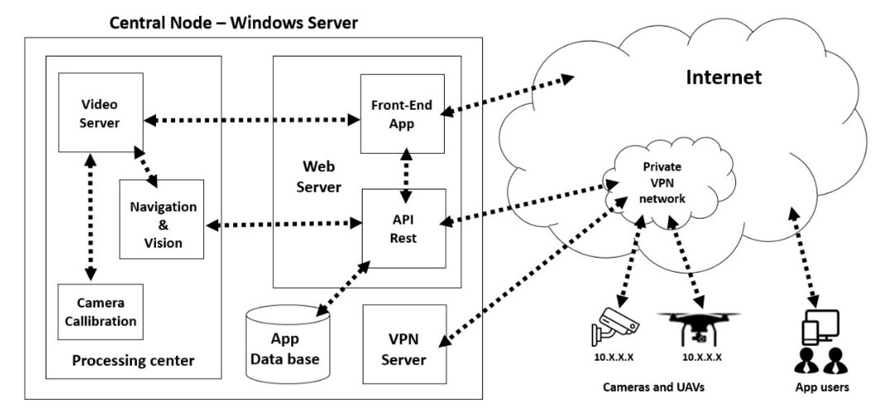
2.2.5. Front- and Back-End Server with Database
The central node consists of a public web server. The missions or tasks to be carried out by the system can be administered, such as surveillance tasks and inspection routines. In addition, it allows real-time monitoring. From this server, all system resources, cameras, drones, processing centers, etc., can be accessed, as can be seen in
Figure 6.
In the central node, there is also a database that is deployed within the VPN network, so it is accessible from any point of the network with very high security levels. In this database, user privileges, flight plans for each aircraft, specifications of work zones, the configuration of each software and hardware element of the system, etc., are stored. Currently, this database is managed with MariaDB, a database management system with high reliability and stability, in addition to being a freely distributed database.
3. Computer Vision
Regarding the computer vision components, a series of software procedures has been developed to efficiently use the cameras registered in the system. The main algorithms are as follows:
Calibration of static cameras;
Take-off and flight control;
Object tracking;
Inspection of solar panels.
3.1. Calibration of Static Cameras
This functionality allows for calibrating static cameras with only two reference points. These points are the camera position and the ground level point that marks the center of the image. It can be obtained directly from the GPS (marked with a red star in
Figure 7). These two points, together with the information of the parameters of the camera, allow the environment to be calibrated for a subsequent simplified 3D reconstruction of the same. The software for calibration of static cameras can be seen in
Figure 8b.
This functionality serves to calibrate in a new flight scenario in a short time and with few manual steps. A highly accurate transform is achieved between image coordinates and real-world coordinates. It is done without the need to make transforms in the perspective correction image. This achieves a very low computational cost in the real-time processing of images from static cameras.
Simplified 3D Reconstruction
The projection of 3D “world” points
(x, y, z)t into the camera’s sensor plane, producing an image discretized as pixels
(u, v)t, is commonly modelled by combining a pin-hole model containing the camera’s internal parameters and projecting 3D points in the camera frame to the image sensor, with a homogenous coordinate transformation matrix containing external camera parameters, mapping 3D points from an external frame to the camera frame. It provides the projection from an external frame of reference to sensor pixels.
In this model, fx, fy, cx, cy are the camera focal length and image center (in pixels), determined from manufacturer specifications or a standard, short-distance calibration using a known pattern. The rotation rij and translation dk components express the external frame axis position and orientation (pose) expressed in the camera frame; determining them is a common problem since they are defined once the camera is mounted on its final working position.
Determining the external frame pose is often performed using the same pattern-based camera calibration by solving the projection of n points (PnP) problem. However, when the camera is installed outdoors covering a large region, this approach would require a huge calibration pattern installed in a known “pose” or determining the position of several 3D points that must then be identified in the image. As this is unpractical, a simplified approach has been taken under the following assumptions:
A mostly levelled ground plane on the area of operation (roughly similar height on all points). A camera installed on an elevated position at some distance from the area of operation, horizontal (camera x axis reasonably parallel to the horizon) and pointing down by a certain angle towards the area of operation.
Then, 3D point coordinates on the GPS frame can be determined from its corresponding position in the image (in pixels) explicitly (back-projection), requiring only the determination of the following two reference points:
GPS-based position of the camera mounting point; if it is on a pole, the position of the base can be determined then the height added.
GPS-based position of a single external point: the point of the ground plane intersected by the optical axis (in practical words, the ground point appearing at the center of the image).
These GPS points can be determined using a GPS receiver installed on them during a relatively long period of time to improve the position resolution. The most critical parameter under this approach is the height difference between the ground plane and the camera; any other way to determine the height difference (i.e., angle and distance measurement) can also be used to improve its estimation in addition to the GPS readings. There is no problem in assuming the height of the ground plane as 0 and the height difference as the camera mounting point height.
With the assumptions above, it is possible to solve for the x and y GPS coordinates of the point identified in the image by pixels (u, v) as
- a)
Constants:
RadImage = angles X, Y y Z in radians of the center of the image on the ground (latitude, longitude, and altitude to the center of the image);
RadCam = angles X, Y y Z in radians of the camera (latitude, longitude, and altitude of the camera);
AxisX = (XRadImage-XRadCam) * localEarthRadius;
AxisY = (XRadImage-XRadCam) * localEarthRadius.
- b)
Calculate rotation y translation homogeneous coordinate matrix: (world to camera)
- c)
Translation vector from camera origin to world 0 (-GPS coordinates of camera): T is set to 0 by taking the origin at the camera center (and adding camera translation later).
- d)
Rotation and translation homogeneous coordinates matrix.
This allows a relatively easy deployment of the camera, and a very fast estimation of 3D positions from camera images. Precision is sacrificed by the assumptions made and the error in the camera and ground reference points determination; however, it is good enough to take the UAV to this point and ensure that the point of interest is within the airborne camera field of view.
3.2. Take-Off and Flight Control
This software allows for controlling the flight of the UAV from a real point of view of the terrain, instead of from an outdated synthesized or satellite image. This feature is important in controlling the UAV over instantaneous events without the need to calculate where the incident has occurred in the plane. This software, which is fed by the configuration of the camera calibration, allows indicating directly on the ground the place where the UAV will start the flight mission, as can be seen in
Figure 8a.
3.3. Object Tracking
The cameras onboard the UAV have three functions:
Accurate positioning over points of interest through closed-loop control of the position of UAVs according to the image of its embedded camera.
The marking, detection of incidents, or tracking of objects (like vehicles or pedestrians) in aerial view images (
Figure 9 shows vehicles and pedestrians tracking).
The landing control in automatic recharging places of the batteries.
The processing of these images is distributed. Flight control feedback (positioning of the UAV at points of interest and landing control) can be local, in onboard hardware. In this way, the control remains precise even if there are connection problems between the base station and the UAV, while the analysis of the images captured by the camera can be performed both on onboard hardware and on ground hardware (such as the central node). This allows human interaction to confirm or rule out whether the points of interest are valid.
Processing time is a critical factor when tracking moving elements or identifying objects in flight. Furthermore, the resolution of the aerial images from the UAV must be very high to gain good detail of the objects/incidence. This requires a great computational cost. To solve this problem, algorithms have been developed that discriminate the search area by reducing the area of the image in which it is most likely to find the objects of interest.
Figure 10 shows the object tracking management algorithm. Considering the location of the object of interest in previous images and the movement of the UAV, it is determined which will be the area with the highest probability of finding the object in the next frame. In this way, the search is limited to this area of the image, reducing the computational cost. In case the search does not provide any results, the search area is expanded, and a search is made again in this expanded area. If the search continues without finding the object, over this enlarged area, the search variations are increased by turning angles, perspectives, etc. If all this fails, the algorithm determines that the marked point (object to follow) has been completely lost. In this case, the search constraints are deactivated and the search process for the element of interest begins again.
On the contrary, if in any of the previous cases the object of interest is found, this information is recorded for the new iteration of the process. Before doing a new search iteration of the object of interest, the probability or certainty with which it has been found is calculated. If the probability is low (sufficient, but low), a copy of the perspective of the object is saved since it is likely that it has a modification such as a twist or semi-concealment. Furthermore, this new position information is used to give new control orders to the UAV.
3.4. Solar Panel Inspection
The images captured by the UAV cameras (See
Figure 11) are transferred and stored in the processing center to be processed offline. In addition, this method has worked with machine learning techniques to detect defects in solar panels [
9]. The results of the application of these algorithms are divided into the following:
Once the images have been categorized, an operator can inspect only those images that indicate possible failures, eliminating the need to review all images.
With the aim of maximizing the efficiency of the system in the work of inspecting solar panels, the method has worked with various artificial intelligence algorithms. These algorithms are based on convolutional neural networks previously trained with datasets focused on solar panels. For this, images taken from a thermal camera converted to grayscale have been used. Convolutional neural networks are characterized by being inspired by the visual cortex of people. Unlike the rest of the neural networks, not all neurons are interconnected, but rather work in subgroups, each one specializing in specific fragments of information.
In this work, there is an inspection of the solar panels at two levels:
The first phase is to detect the solar panels at the photovoltaic station, which is a different problem from inspection. It works with color and monochrome images. Color images provide better results but carry a higher computational cost.
The artificial intelligence algorithm (see
Figure 12) begins in the first layers of neurons. This extracts the most basic information, such as lines, strokes, and simple colors or tones. As is deepened in layers, solar panels are detected. Finally, its status is determined, based on its coloration and its location.
In this segmentation phase, we work with low-resolution images, the size of said image, and the encoding of said image in color. The number of color channels used will determine the number of neurons that will make up the first layer of the neural network. The image is reduced to resolutions of 800 × 600 px. When working with monochrome images, only one layer of 480,000 neurons is needed. Meanwhile, if it is performed with RGB images, 1,440,000 will be necessary, which means 300% more computation. The result of this phase is a grid delimiting the inspected area that belongs to the individual solar panels.
In this phase, the already segmented image is processed (only the areas of interest referring to solar panels). This image is smaller, but of a higher resolution and in monochrome (thermal image). Like the previous phase, the size of the image represents the initial layer of the neural network. However, in this case, its size can be reduced since the search area is limited from the previous phase. In this phase, the main elements are the intermediate layers of the network or convolution layers. This layer takes groups of pixels close to each other in the image and performs operations with another matrix called “kernel”. A kernel represents a filter, a feature that is searched by this neural network. The result will be the value obtained by that group of pixels for that characteristic.
In other words, these kernels will search for the following within the images:
Grids representing the cells of the solar panels;
Areas with a higher temperature (light colors);
Areas with a lower temperature (dark colors);
Areas where different temperatures converge gradually;
Shapes or silhouettes of potential failures.
After filtering, a feature mapping of the entire image is obtained with the most striking characteristics. These are represented by scores for each pixel in each kernel. Before performing a new convolution, a process called subsampling is performed, where the image is reduced in each operation so as not to exponentially increase the computational cost. For example, for a 4 × 4 matrix, it is simplified using the max-pooling method, as can be seen in
Figure 13:
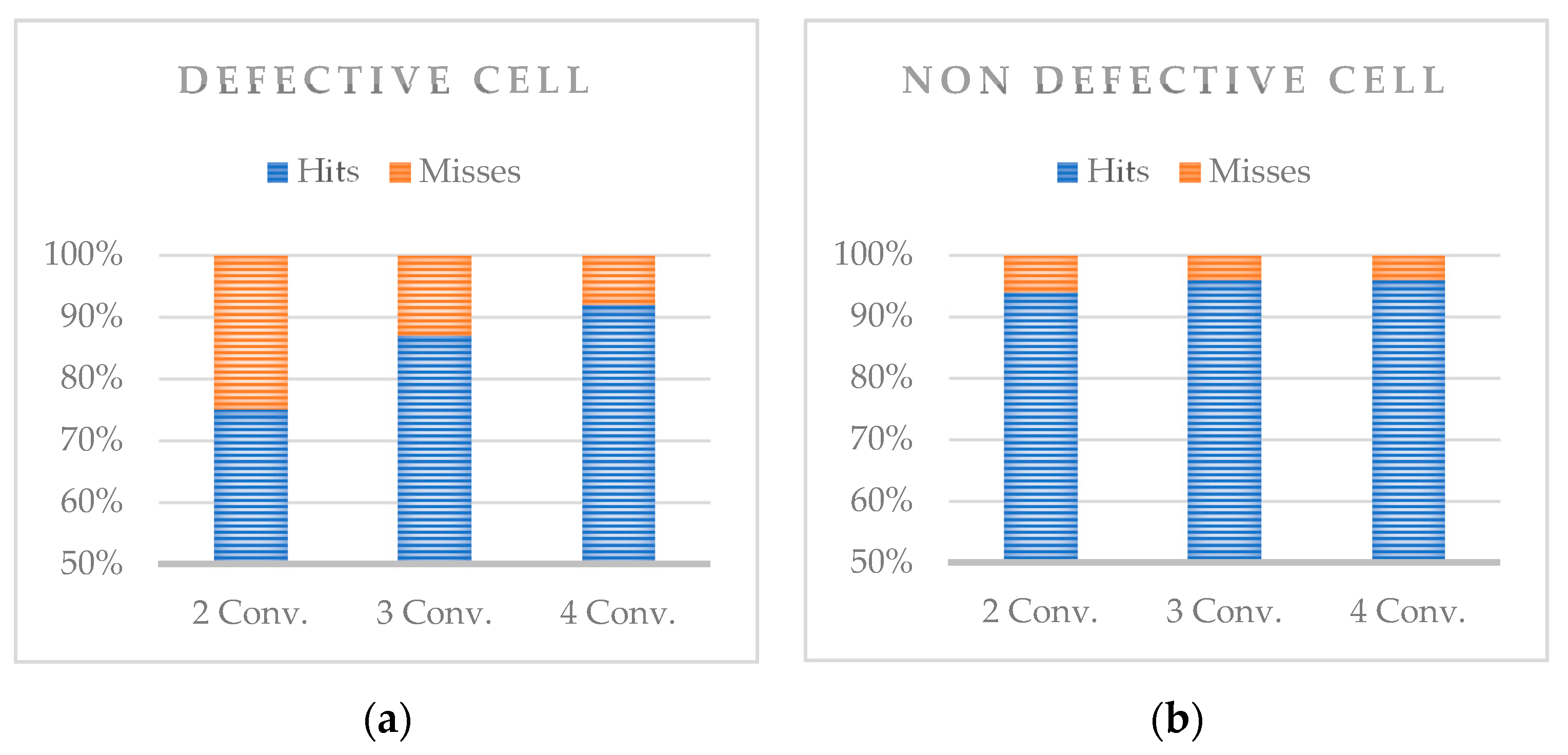
In this case, the process determines the areas of the image that define a high probability that there is a defect in that area. By expanding the number of convolutions, more complex filters are achieved. These yield a new feature mapping that is later simplified. In each new convolution, more complex information from the image can be recognized to improve detection or classification. The results that have provided a better score in the image set have been achieved in the range of two to four convolutions. A greater number of convolutions does not significantly increase the score of the results, but instead increases the computation time considerably.
The last step involves connecting the convolutional neural network to a “traditional” neural network. To this network, a function called “SoftMax” is applied which will result in the output layer. This layer is made up of as many neurons as possible outcomes can be. For this case, the outputs would be: defect detection, or no defect has been detected.
5. Discussion and Conclusions
This article has described an architecture for remote UAV fleet management for maintenance, inspection, surveillance, and security in solar power plants. Some of the most prominent conclusions about this work and whose implementation represents a competitive advantage in the sector are those described below.
The use of UAV to track pedestrians and vehicles provides great benefits for road safety as well as for the safety of solar plants, for example, to detect pedestrians who cross a road incorrectly or who are traveling on a secondary road incorrectly, detection of vehicles that are performing incorrect maneuvers such as driving in the opposite direction on a highway, prohibited direction changes, excessive speeds, and dangerous driving, or even to locate and monitor vehicles and their occupants from the control center in a traffic accident or accessing restricted areas without authorization.
A UAV equipped with a thermal camera, depending on the flight height, flight speed, and the type of built-in camera, can inspect around 35 square meters of solar panels per second. This entails carrying out an inspection flight over one hectare in about 5 min. Therefore, in a full flight of about 25 min in duration, a full inspection of a five-hectare area can be performed. Since these images are stored in the central server and accessible from outside the solar plant, an operator could manage the inspection. The possible faults can be identified automatically in the images captured remotely.
The results shown in
Section 4.2 have been obtained empirically for a specific resolution. Since no inspections have been performed with other cameras of different resolutions, it has not been possible to determine how the resolution affects the computation time and accuracy. For images with different resolutions, it is possible to pre-resize each image to be fully compatible with the architecture of the trained convolutional neural networks. In the case that only the lenses are changed and the resolution is maintained, the processing time would not be affected, however, the accuracy may be slightly affected. It can occur due to the neural networks being trained for images obtained with a specific lens and focus.
The use of this system supposes a drastic decrease in the time required to carry out inspections on solar power plants. Daily inspections can be carried out at a very low cost to monitor the operation of its elements, detecting early failures in the solar panels, or to carry out surveillance tasks and prevent theft or vandalism (including night surveillance).
Another important competitive advantage is eliminating the need for an operator to travel to the solar plant to perform a manual inspection. The system proposed in this paper allows remote inspection from any mobile device with internet access.
Inspection time is reduced due to the recategorization of possible defective areas by machine learning algorithms (deep learning). With this new approach, a single operator could inspect more than one solar plant per day.
Finally, the proposed system results in greater efficiency in the inspection of solar plants, reduction in operator costs, and early detection of panel failures. This would maximize energy production and reduce maintenance costs, increasing its competitiveness against other sources of renewable energy. Among future lines, it is intended to study the integration of forecasting methods in the architecture to maximize the efficiency of the whole system.


 ,
, 


