Article

Energy Harvesting by Waste Acid/Base Neutralization via Bipolar Membrane Reverse Electrodialysis

Engineering Department, University of Palermo, Viale delle Scienze, Ed. 6, 90128 Palermo, Italy
*
Author to whom correspondence should be addressed.
Energies 2020, 13(20), 5510; https://doi.org/10.3390/en13205510
Submission received: 21 September 2020 / Revised: 13 October 2020 / Accepted: 19 October 2020 / Published: 21 October 2020
(This article belongs to the Special Issue Emerging Membrane Technologies for Energy Production)

Abstract

:
Bipolar Membrane Reverse Electrodialysis (BMRED) can be used to produce electricity exploiting acid-base neutralization, thus representing a valuable route in reusing waste streams. The present work investigates the performance of a lab-scale BMRED module under several operating conditions. By feeding the stack with 1 M HCl and NaOH streams, a maximum power density of ~17 W m−2 was obtained at 100 A m−2 with a 10-triplet stack with a flow velocity of 1 cm s−1, while an energy density of ~10 kWh m−3 acid could be extracted by a complete neutralization. Parasitic currents along feed and drain manifolds significantly affected the performance of the stack when equipped with a higher number of triplets. The apparent permselectivity at 1 M acid and base decreased from 93% with the five-triplet stack to 54% with the 38-triplet stack, which exhibited lower values (~35% less) of power density. An important role may be played also by the presence of NaCl in the acidic and alkaline solutions. With a low number of triplets, the added salt had almost negligible effects. However, with a higher number of triplets it led to a reduction of 23.4–45.7% in power density. The risk of membrane delamination is another aspect that can limit the process performance. However, overall, the present results highlight the high potential of BMRED systems as a productive way of neutralizing waste solutions for energy harvesting.

1. Introduction

Disposal of acidic and alkaline wastes is a crucial issue from the economic and environmental point of view. Large volumes of acidic wastewater are produced in many industrial processes, from electroplating, iron and steel production to pickling operations, from food processing to drugs production and mining activities. Thus, acidic wastewater disposal is one of the most important issues for the modern industries, since wastewater must be treated under controlled conditions before the final discharge. A common practice in treating acid streams is the neutralization process with a large amount of alkaline reagents (e.g., calcium carbonate, calcium oxide, magnesium hydroxide, sodium hydroxide or carbonate) [1]. This implies significant costs for disposal and the need of further treatments for the produced sludge containing heavy metal compounds. Furthermore, valuable acid is lost during neutralization processes, while it could be recovered and/or reused through a sustainable approach. Many technologies are currently studied for acid recovery [2,3], including electrodialytic techniques [4,5]. Similar considerations apply for alkaline solutions. High amounts of spent sodium hydroxide solutions are regularly disposed of by several industry sectors. A typical source of caustic soda wastes is the anodizing industry, which uses highly concentrated NaOH solutions at high temperature, particularly for removing aluminum from the extruder matrixes [6]. In fact, the inner surface of the extrusion dies has to be perfectly clean in order to produce high quality extruded products [7]. The textile dyeing industry as well as metal finishing processes are other sources of caustic soda with an average concentration of 12% weight. The outgoing spent caustic soda solutions present an average concentration of 4% weight, which is typically lost by neutralization [8]. Sodium hydroxide solutions with a concentration in the range 5–10% weight are commonly used in the oil refining desulfurization process, which produces consumed caustic soda solutions [9]. Finally, spent caustic soda solutions are also produced by ethylene plants [10].
In order to reduce the treatment costs for acid and base wastewaters, they could be used to recover energy. For this purpose, several approaches have been proposed over the years. A solution consisted in harvesting mechanical energy by carrying out the neutralization reaction, with waste acid or base, inside an ion-exchange polymer causing a reversible swelling and shrinking of the polymer phase because of the water transport inwards and outwards [11,12,13]. Another approach involved the energy storage derived by the proton insertion/de-insertion cycle in a so-called neutralization pseudocapacitor, where energy storage was derived from the partial entropy change related to the difference in the acid concentration of the electrolytic solution [14].
An innovative way in reusing waste acid/base streams for energy production can be based on harvesting the mixing energy, i.e., neutralization, through Reverse Electrodialysis (RED). This technology has been extensively studied for the production of electricity by a controlled mixing of solutions of different salinities, exploiting the so-called Salinity Gradient Energy (SGE) [15,16,17,18]. This is possible by means of Ion Exchange Membranes (IEMs) that are used to exploit the chemical potential difference between solutions at different concentrations by controlling the ions’ movement. RED systems have been widely studied in the last decade, assessing the influence on stack performances of different operating conditions (e.g., streams flow rates and concentration, temperature) [19,20,21,22,23,24,25], different process designs [26,27,28], different installation scenarios [29] (even at the prototype scale [21]) and of the properties of the IEMs [30,31,32,33]. Moreover, the RED technology has been proposed to produce energy from waste solutions [34,35,36]. In this regard, an ammonium bicarbonate-based Reverse Electrodialysis system was proposed to treat waste acid streams and, simultaneously, to produce hydrogen gas [37]. Whenever wastewater streams are fed to RED systems, it is crucial to take into account fouling issues (especially in anion exchange membranes) as well as the negative effect associated with the presence of multivalent ions with real streams, that could lead to worse performances [38,39,40,41,42,43]. Mei et al., proposed an RED chemical cell fed with acid, base and neutral solutions in a four-compartment unit configuration, to produce energy from acid/base neutralization [44]. With 0.3 M HCl/NaOH solutions and 0.01 M NaCl neutral solution, a maximum gross power density (GPD) of ~0.5 W m−2 was achieved. With respect to that obtained by conventional RED with only neutral solutions, the GPD was significantly enhanced.
However, such a process may be further improved by including the bipolar membranes. Bipolar membranes are composed by a Cation Exchange Layer (CEL) and an Anion Exchange Layer (AEL) connected by a catalytic interlayer and are usually adopted to produce/regenerate acid and base solutions from a salt stream by the Bipolar Membrane Electrodialysis (BMED) process [45,46,47,48,49], via water dissociation (H2O → H+ + OH) under an applied electric field. Making an analogy with the p-n semiconductors junction, bipolar membrane (BPM) is under reverse bias condition during the BMED process [50]. Bipolar Membrane Reverse Electrodialysis (BMRED) is the reverse process, which allows energy to be produced by controlling the mixing of acid and base solutions. In both technologies, the repeating unit, namely the triplet, is composed by one anion-exchange membrane (AEM), one BPM and one cation-exchange membrane (CEM) separated by polymeric spacers. In BMRED, protons and hydroxyls react inside the BPM (at bipolar interface) producing water (H+ + OH → H2O) that then diffuses across the CEL and AEL of the bipolar membrane (Figure 1). The working principle of BMRED is similar to that of conventional RED. It relies on the electrochemical equilibrium related to the co-ion exclusion, which implies the occurrence of an electrical potential over each membrane between two solutions at different concentrations. In particular, the major driving force of BMRED systems is represented by the pH gradient over the BPMs. The stack electromotive force is given by the contributions of all membranes. Under conditions of closed circuit, an electric current flow through the stack due to the selective ion transport across the membranes, while redox reactions at the electrode compartments convert it into an external electronic current.
Only a few research efforts have been devoted to BMRED so far. In all cases, the BMRED process has been studied in the framework of acid/base flow batteries for energy storage. In Table 1, an overview of literature data on BMRED systems is reported.
In a previous work, we developed a mathematical model of the acid/base flow battery [57]. The sensitivity analysis performed by the process model showed that, at high numbers of repeating units, parasitic currents were the most detrimental among the unwanted phenomena.
This brief literature review shows that the BMRED technology has been poorly studied so far. Moreover, it has been considered only within acid/base flow batteries. However, the BMRED process may represent an option to recover energy from waste acid and base. In this work, we present the results of an extensive experimental campaign on the electrical energy harvesting by the controlled neutralization of acidic and alkaline streams via BMRED, in order to elucidate the effect of several operating parameters, identify the possible room for improvement and assess the application potential. We investigated the performances of a BMRED lab-scale module, evaluated in terms of Open Circuit Voltage (OCV) and GPD as functions of different operating parameters, such as number of triplets, composition of electrode rinse solution, streams flow rate, and acid (HCl)/base (NaOH) streams concentration and composition. This last parameter was also investigated by adding NaCl in acid and base solutions, in order to characterize the stack fed by simulated wastewaters and to mimic the co-ion leakage occurring in long-term operations or scaled-up units.

2. Materials and Methods

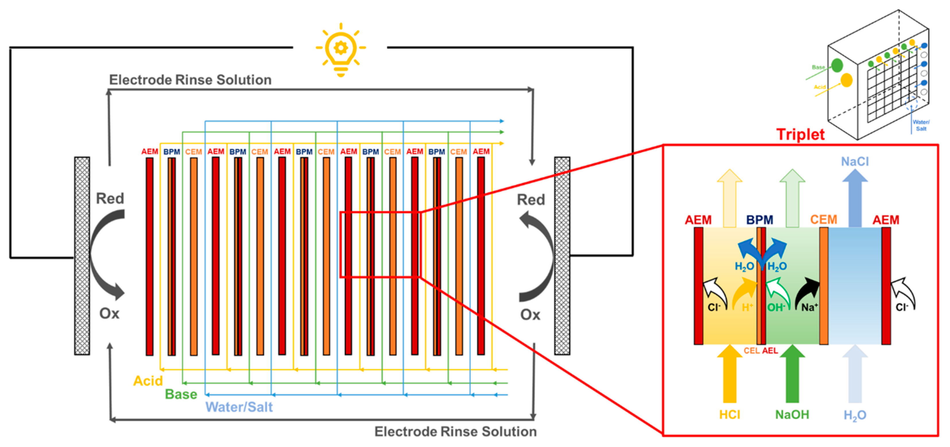
2.1. Ion Exchange Membranes

Commercial IEMs (AEM: fumasep® FAB, CEM: fumasep® FKB, BPM: fumasep® FBM), whose features are reported in Table 2, were purchased from Fumatech BWT GmbH (Germany). These membranes are efficiently used in (bipolar) electrodialysis processes thanks to their high chemical stability within a broad pH range. The membranes were continuously conditioned in 0.25 M NaCl solution before and after testing. In the case of the BPM, continuous wetting is crucial to prevent shrinkage and consequent damage.

2.2. Stack and Solutions Characteristics

A lab-scale module (FT-ED-100) was purchased from Fumatech BWT GmbH (Germany). The electrodes were DSA (Dimensionally Stable Anode)-type electrodes, suitable for the redox electrode reactions, with an area of 10 × 10 cm2. The repeating unit (namely triplet) was composed of one AEM, one BPM and one CEM, separated by PVC/ECTFE spacers (made by woven filaments and with a thickness of 500 µm) [58]. Spacers had three inlet/outlet holes per channel and each hole diameter was 8.5 mm. Membranes’ active area was 10 × 10 cm2. The stack was assembled with different numbers of repeating units: 5, 10, 20, 30 and 38 triplets.
Artificial acid, base and salt solutions were prepared using Hydrochloric Acid (HCl 37% Merck), Sodium Hydroxide (NaOH 98–100% Honeywell Fluka) and Sodium Chloride (NaCl 99.7% ChemSolute), respectively. Acid and base streams were fed to the stack with equal initial concentration (i.e., 0.2 M, 0.6 M or 1 M aqueous solutions), the salt stream was an aqueous solution 0.25 M in NaCl in every test. In order to simulate wastewaters and to mimic the co-ion leakage occurring in long-term operations or scaled-up units, every measurement was repeated by adding NaCl (0.25 M) to acid and base solutions. Aqueous solutions 0.25 M in Na2SO4 (99% Honeywell Fluka) and 0.5 M in FeCl2/FeCl3 (99% ChemSolute) were preliminarily tested as electrode rinse solutions (ERSs). In the former case, a CEM was used as end membrane while, in the latter case, an AEM was used as end membrane and HCl was added to the ERS to maintain the solution pH lower than 2.3 to prevent possible iron oxy-hydroxide precipitation [59]. Electrode rinse solution was recirculated between cathode and anode compartments with a flow rate of 600 mL min−1. Preliminary experiments confirmed literature findings relevant to RED systems: the stack performance is higher when FeCl2/FeCl3 ERS are adopted (see Appendix A). Thus, all the experiments presented in this work were carried out with this ERS. Peristaltic pumps (BT601S, Lead Fluid Technology, CO LTD, China) were used for circulating all the acid, base and salt streams as well as the electrode rinse solution. Acid, base and salt solutions were fed in single-pass configuration, conversely, ERS was recirculated between the electrode compartments in a closed-loop configuration as shown in Figure 1.
All the measurements were performed at room temperature and were repeated three times. Only a very small difference was found in the measured variables: in particular, the corresponding error bars were so small that they are not visible in the following figures (i.e., error bars smaller than the experimental point in the graphs). The flow rate of acid, base and salt streams was set to have fluid velocities in the channels of 0.5, 1.0 or 1.5 cm s−1. Acid and base solutions were fed to the stack with a co-current flow distribution, whilst salt solution was fed in cross-flow with respect to them (see inset of Figure 1).

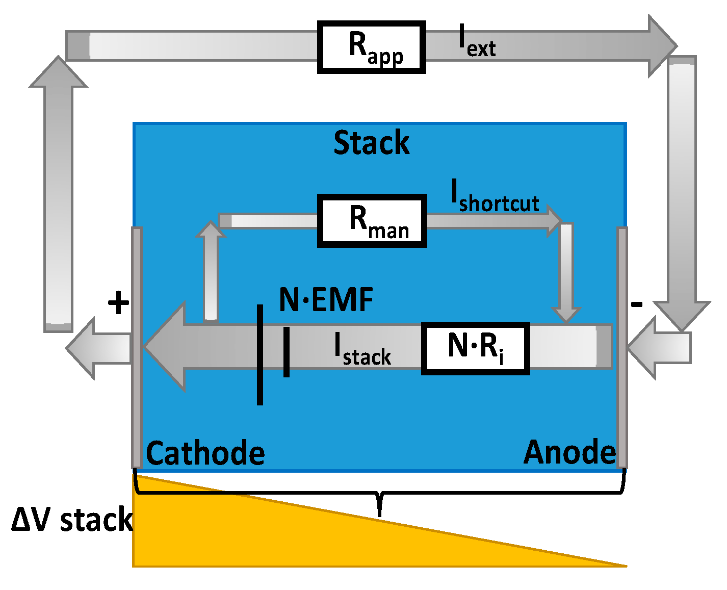
2.3. BMRED Module Characterization

The BMRED process performances were evaluated by recording stack voltage vs. current density curves in galvanostatic mode, i.e., a constant current density was applied to the stack while recording the voltage until a stationary value was reached. Before every measurement, the Open Circuit Voltage (OCV) was recorded. A BK Precision 8540 DC Electronic Load was used for all the measurements. The gross power density (GPD, expressed as W m−2 total membrane area) was calculated at the various values of applied current, and the apparent stack resistance was estimated from the slope of the current–voltage curve according to Ohm’s law.

3. Results and Discussion

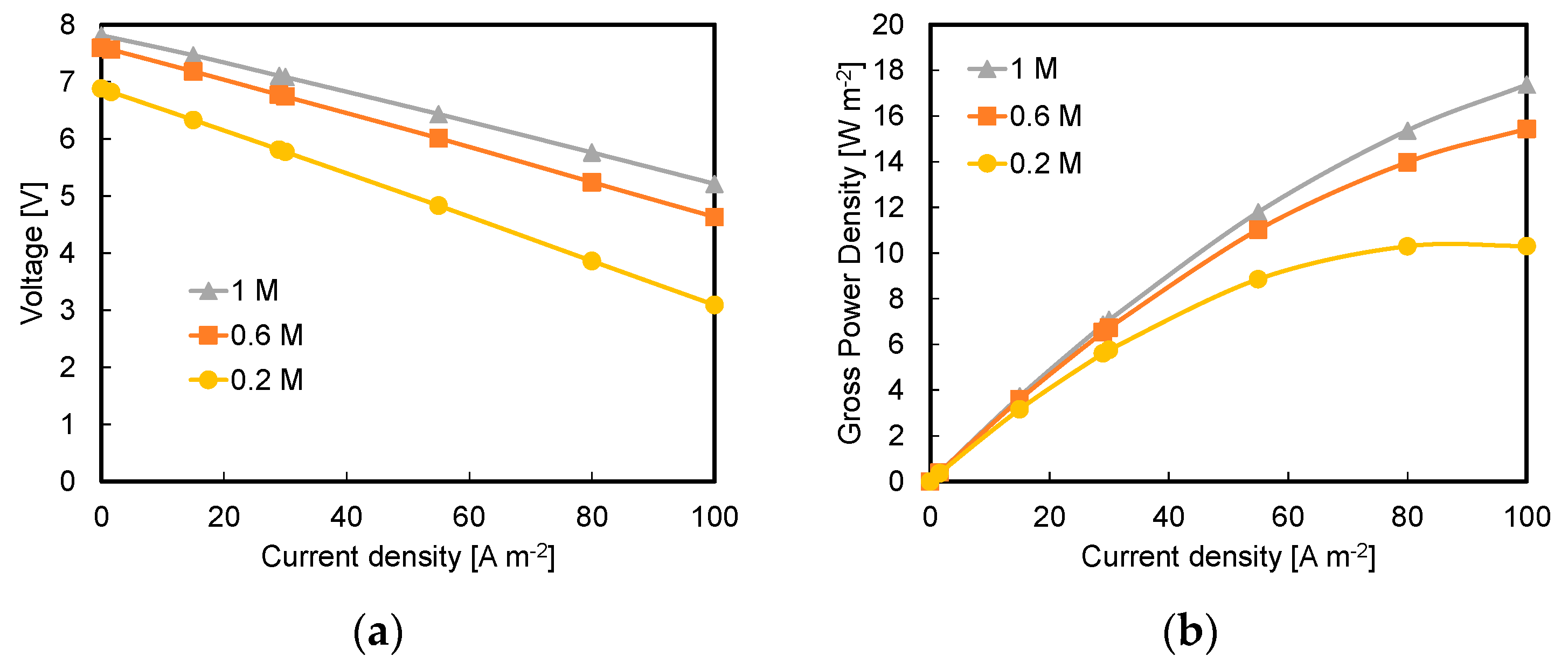
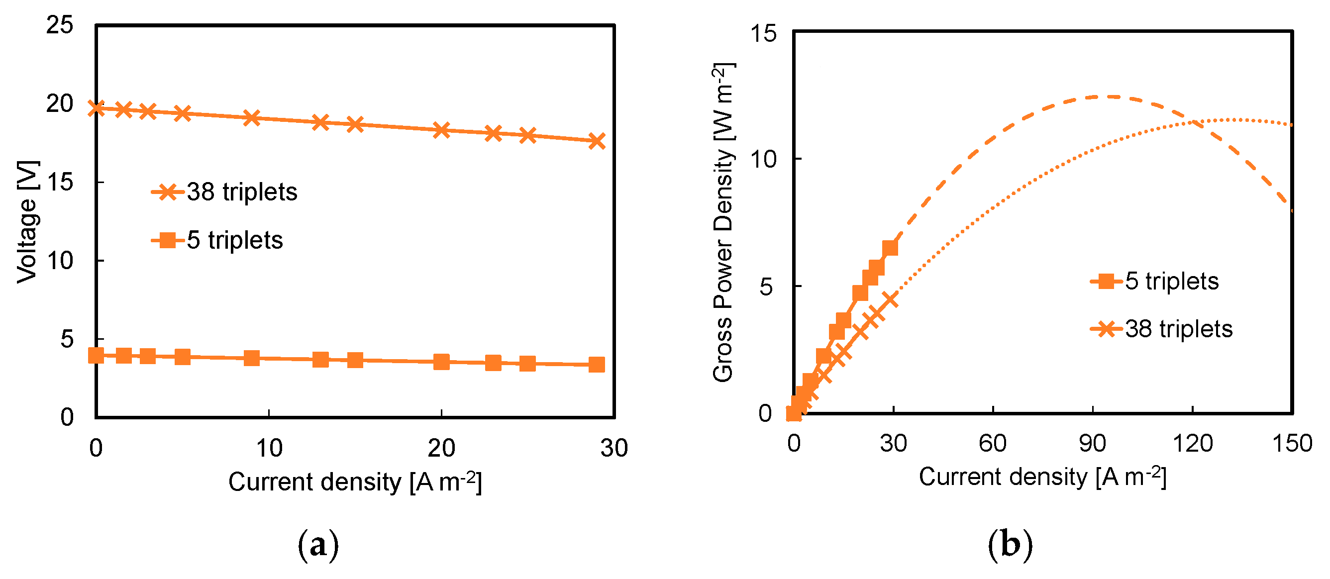
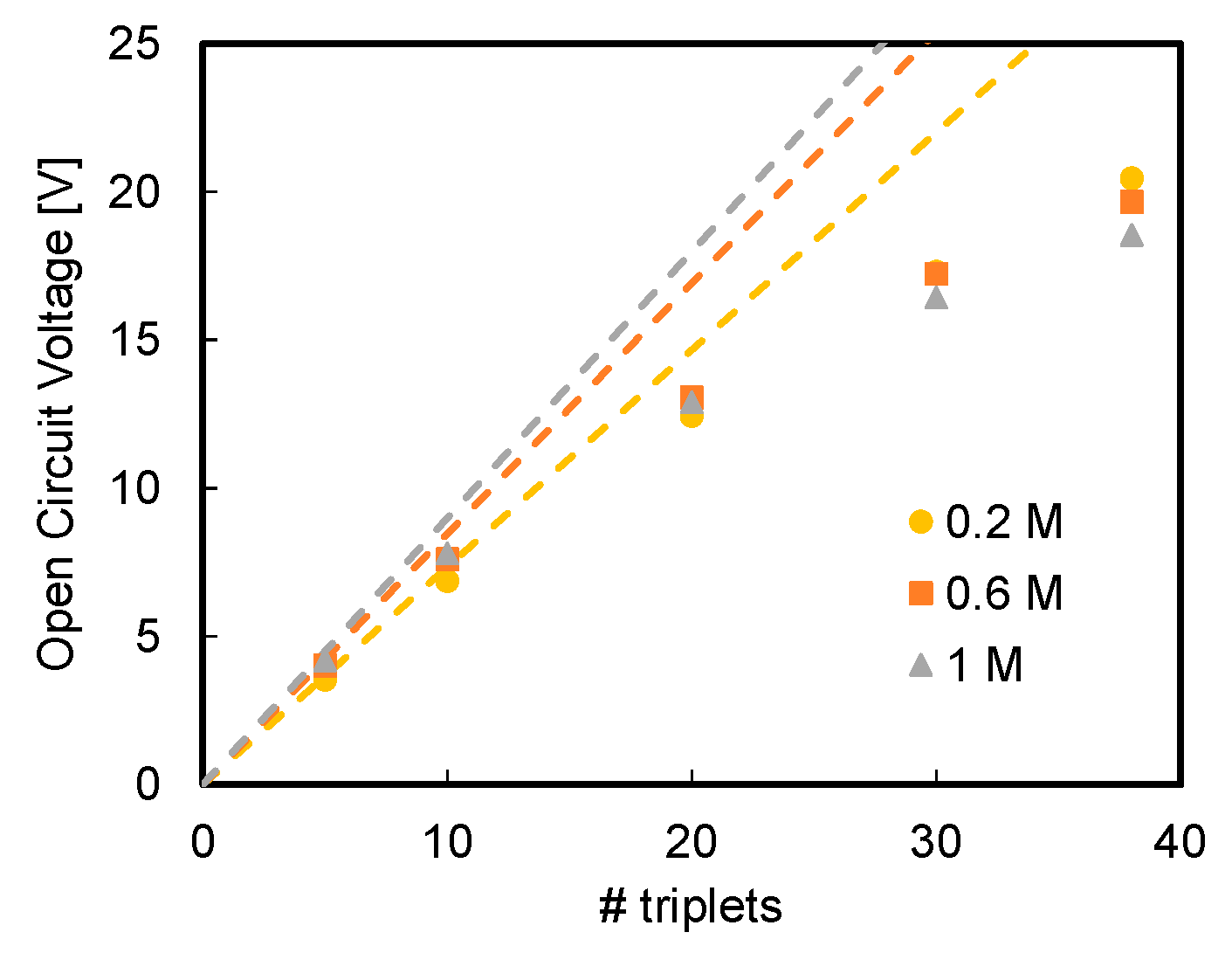
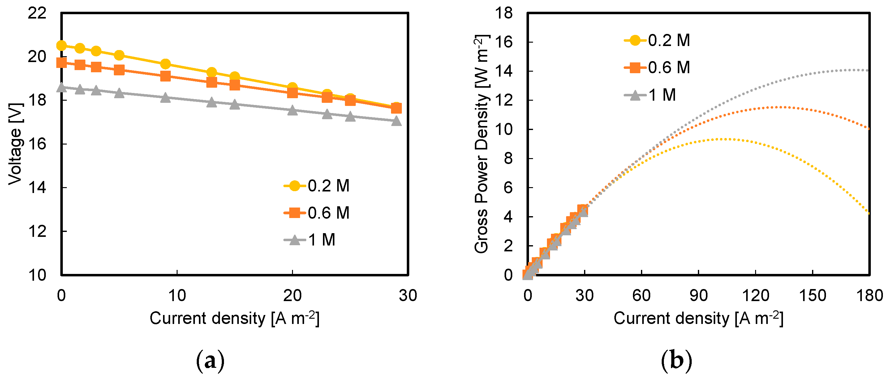
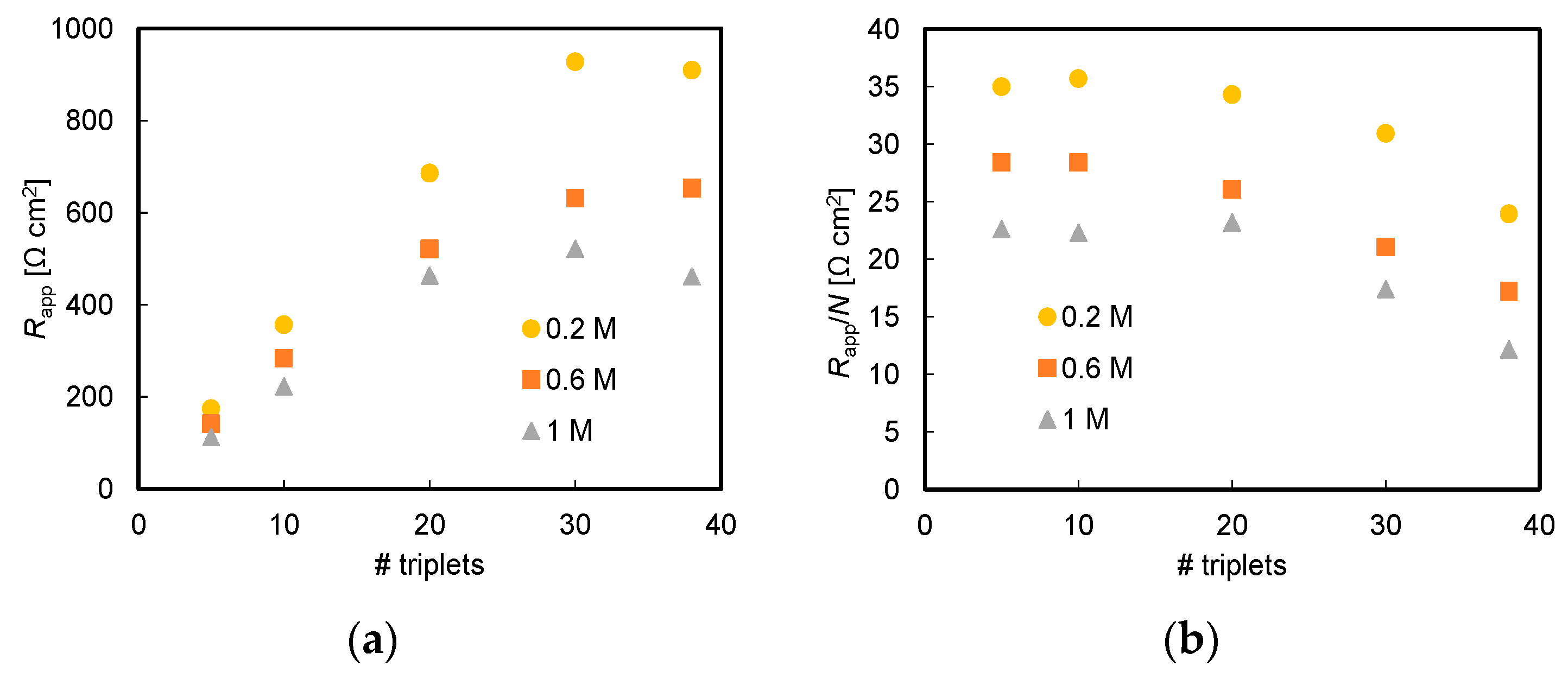
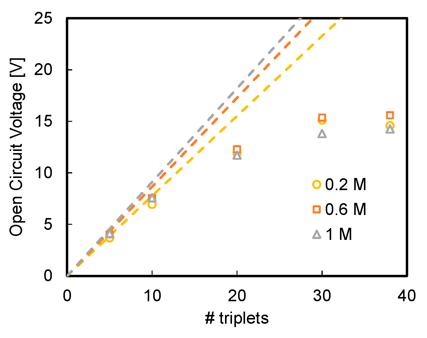
3.1. Effect of Acid and Base Concentration and of Number of Triplets

Stack characteristics collected by changing the inlet composition of acid and base streams (0.2 M, 0.6 M and 1 M of HCl and NaOH) are reported in Figure 2a for a stack composed of 10 repeating units, with a fixed flow velocity of 1 cm s−1.
The measured OCV increases by increasing acid and base concentration, from 6.88 ± 0.1 V (0.2 M) to 7.8 ± 0.1 V (1 M), as a consequence of a higher pH gradient across the bipolar membranes.
These OCV values are quite impressive if compared with those that can be generated by exploiting salinity (NaCl) gradient only. In fact, considering two pure NaCl streams of 1 g L−1 and 30 g L−1 (i.e., artificial river and sea water, respectively) and ideally selective ion exchange membranes, ~50 repeating units (100 membranes) are needed to generate the same OCV values obtained with a BMRED stack composed by 10 repeating units (30 membranes) and fed with 1 M acid and base solutions. The relative differences with respect to the 1 M case were on average 6.1% and 14.5% at 0.6 M and 0.2 M of acid/base, respectively. Concerning the power density (see Figure 2b), the maximum measured value was of 17.4 ± 0.2 W m−2 and was obtained in the case of 1 M at 100 A m−2. At the same fixed current, power densities were 11.1% and 40.7% lower in the case of 0.6 M and 0.2 M acid/base, respectively. It is worth noting that the power peaks (i.e., the maximum point of the parabola) should occur at current density higher than 100 A m−2 in the tests with 0.6 M and 1 M streams whilst, with 0.2 M as acid/base concentration, the power peak has been reached at a current density between 80 and 100 A m−2. It is interesting to note that the reached power densities are higher than the maximum power densities measured so far with lab-scale units exploiting NaCl salinity gradients (~6.7 W m−2) [20,60]. With 0.2 M acid/base solutions, the maximum GPD is ~10.3 ± 0.2 W m−2, which is much higher than the maximum GPD (~0.5 W m−2) achieved by Mei et al. with 0.3 M HCl/NaOH solutions fed to an RED stack equipped with only monopolar membranes (MPMs), with a four-compartment configuration [44]. Testing a BMRED stack similar to that of the present work, but with 20 triplets, fed by 1 M acid/base streams, Xia et al. [56] reported a GPD of ~16 W m−2 excluding the electrode losses (ERS: Na2SO4), which is slightly lower than the maximum value found here. In comparison to RED systems with only monopolar membranes using acid and base streams [44], the high GPD values obtained in the present experiments are caused by the synergistic effect of the high OCV generated by the system, thanks to the pH gradient across the BPM, and of the low stack resistances due to highly conductive acidic and alkaline solutions and to the very low thickness (<10 nm) of the actual “diluate stream” represented by neutral water in the BPM interlayer. In comparison with the similar equipment used by Xia et al. [56], their lower maximum GPD can be attributed to detrimental effects taking place as the number of triplets is increased (they used a stack with 20 triplets).
It is important to observe that voltage vs. current density curves shown below were recorded without exceeding a current density of 29 A m−2. This very conservative limit was fixed to avoid possible delamination of the bipolar membranes. In fact, during the BMRED process, the neutralization reaction of H+ and OH that occurs inside the interlayer of the bipolar membranes produces water that, if not properly drained by diffusion through CEL and AEL of BPM, can accumulate thus leading in the worst case to the detachment between the ion exchange layers. As shown in Figure 2a,b, higher currents should be possible, but further investigations are needed, especially during long runs. However, given (i) the preliminary nature of the present work, (ii) our limited availability (due to current cost) of bipolar membranes and (iii) the need for performing experiments with a large number of BPMs (i.e., 38 triplets stacks, see below), ~29 A m−2 was considered as a reasonable conservative limit for the purpose of the present work.
The effect of the number of triplets on the BMRED module performances can be observed from the curves reported in Figure 3a, comparing the performances of a stack composed by five triplets with that equipped with 38 triplets with acid and base inlet concentration fixed at 0.6 M and a flow velocity of 1 cm s−1. First, there is not a proportional increment of the OCV with the number of triplets. Moreover, limiting the curves at 29 A m−2, the GPD that can be delivered by a five-triplet module is even higher than that delivered by a 38-triplet module (6.5 ± 0.2 W m−2 and 4.5 ± 0.1 W m−2, respectively). At (extrapolated) higher current densities, Figure 3b, a smaller difference can be observed under maximum GPD conditions, suggesting that the effects of the number of triplets depend on the applied current and, in particular, decrease as the current increases [61]. Anyway, the 38-triplet stack would cover a much larger range of current density, exhibiting the extrapolated maximum GPD at ~150 A m−2 against the ~100 A m−2 of the five-triplet stack, likely due a lower apparent resistance of the triplet associated to parasitic currents and/or to be the smaller relative effect of the blank resistance.
To further investigate the effect of number of triplets on the module performances, OCV values as a function of number of repeating units are reported in Figure 4 for all the investigated acid and base solutions concentrations.
The measured OCV does not follow a linear dependence on the number of triplets, rather it is lower than the expected ideal value (namely electromotive force, EMF, see dashed lines in Figure 4), estimated as the sum of the BPM membrane potential due to the pH gradient and the contributions of salinity gradients across CEM (Na+ ions) and AEM (Cl ions). Thus, EMF can be calculated by the Nernst equation as follows [54]:
E M F = N [ R g   T   z F ( l n a H + | a c a H + | b p + l n a O H | b p a O H | b a + l n a N a + | b a a N a + | s a + l n a C l | s a a C l | a c ) ]
where a is ion activity, Rg is universal gas constant (8.314 J mol−1 K−1), T is temperature, z is ion oxidation number, F is Faraday constant (96,485 C mol−1), ac, bp and ba refer to the acidic solution/CEL interface, interlayer of the bipolar membrane and the alkaline solution/AEL interface, respectively and N is the number of triplets. It is important to say that, in the calculation of EMF with Equation (1), the membranes are considered 100% permselective and ions activity coefficient is assumed to be equal to 1. The significant difference of the measured OCV from the ideal linear trend as a function of the number of triplets is related to the presence of parasitic currents, (also known as shunt currents or ionic shortcut currents or leakage currents), caused by the unwanted ion transport through alternative paths via manifolds (i.e., collectors and distributors) [61,62,63,64].
It can be clearly observed that this effect is more pronounced by increasing the concentration of acid and base streams and by increasing the number of repeating units. In fact, the lowest OCV values for stacks with 30 and 38 triplets were measured with 1 M as concentration, despite the higher pH gradient.
As with classical RED systems [20], it is possible define an average apparent permselectivity for BMRED systems, αBMRED, estimated as:
α B M R E D = O C V E M F
where OCV is that experimentally measured and EMF is calculated according to Equation (1). αBMRED decreases by increasing inlet acid/base streams concentration (for a 10-triplet stack it decreases from 0.94 for 0.2 M HCl/NaOH to 0.87 for 1 M HCl/NaOH), and strongly decreases at a high number of triplets (0.54 in the case of 38-triplet stack and 1 M HCl/NaOH feeds concentration) (see Figure 4). It is clear that, in the latter case, this parameter not only accounts for the selectivity of single membranes but, mostly, for the presence of the parasitic current that leads to lower OCV values.
In order to discuss what happens with a high number of repeating units, Figure 5a reports the stack voltage and the power density as a function of the applied current for the stack with 38 triplets.
For any applied current density, the stack voltage is lower as the inlet concentration (and thus the pH gradient) increases, especially under open circuit conditions. This results in lower values of GPD at 1 M inlet concentration in the investigated range of 0–29 A m−2. However, the differences in GPD among the various inlet concentrations are less marked than those in terms of voltage, due to the lower stack resistance at higher concentrations (see the lower slope of the voltage–current density curve from 0.2 to 0.6 M and to 1.0 M). As a result, the power density delivered below 29 A m−2 by a stack composed of 38 repeating units is almost the same regardless of inlet acid and base concentration. However, the highest maximum power density value (i.e., 14 W m−2) would be reached anyway with 1 M acid and base streams because of the lower stack resistance (see Figure 5b where the GPD curves are extrapolated up to higher current density). In addition, this behavior could be also partly attributed to the lower parasitic currents at higher external currents [61].
By comparing the performance of the five-triplet and 38-triplet stacks, it is possible to note that higher GPD values can be reached with the five-triplet stack with respect to those reached with the 38-triplet stack at all the different acid and base inlet concentrations. At the maximum current density tested (29 A m−2) the GPD is reduced on average by 25–30% passing from 5 to 38 triplets. At the maximum GPD extrapolated, the differences are lower.
It is also interesting to observe the dependence of the apparent stack resistance on the number of triplets. The stack resistance can be obtained from the slope of the voltage vs. current density curve by applying the Ohm’s law, but it is only an “apparent” resistance (Rapp,stack) due to the presence of parasitic paths via manifolds. Notably, the blank resistance (measured by using only one AEM between the two electrode compartments) was removed (Equation (3)) in order to observe the effect of N only in terms of parasitic currents. Therefore, Rapp represents here the apparent resistance of N triplets:
R a p p = R a p p , s t a c k R b l a n k
Rapp and Rapp/N are reported as functions of N in Figure 6a,b, respectively, for all the tested inlet concentrations.
Looking at Figure 6a, it is possible to note that Rapp increases linearly up to 20 triplets but then shows a deviation from linearity for a stack mounting 30 and 38 triplets, regardless of the concentration of acid and base solutions. In the case of Rapp/N (see Figure 6b)), it is almost constant up to 20 triplets and then decreases by increasing the number of triplets. These trends can be qualitatively explained by solving the simplified equivalent electric circuit of the system shown in Figure 7.
According to this simplified scheme, the apparent resistance of N triplets can be expressed as:
R a p p = V s t a c k I e x t = R m a n   R a p p R m a n + R a p p N   R i + R m a n   R a p p R m a n + R a p p N   E M F I e x t
where Vstack is the stack voltage, Iext is the electric current flowing in the external branch, Rman and Ri are the manifolds and the cell triplet resistances, respectively. Rman represents the parasitic resistance of a much more complex equivalent electric circuit with multiple branches, and it is a decreasing function of N: it is well known that by increasing the number of repetitive units, parasitic currents phenomena increase their impact [61,63]. Therefore, at any Iext, Rapp can be estimated from Equation (4). As a result, it is easy to find that Rapp and Rapp/N as functions of N will follow qualitatively the trends shown in Figure 6, i.e., the former will deviate from linearity and the latter will decrease. This corresponds to the fact that, as N increases, the parasitic current Ipar and the useful current flowing inside the stack in the direction perpendicular to the membranes Istack increase.
It is worth noting that hydraulic features suitably designed can be devised to tackle this issue at an industrial level (e.g., blocks of triplets hydraulically separated).

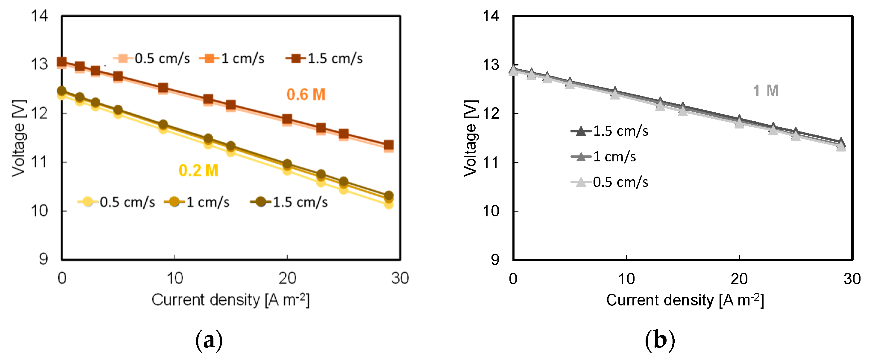
3.2. Effect of Flow Velocity

The aim of the controlled neutralization is to maximize the electric energy which can be recovered from waste acid. In order to do so, it may be crucial to keep the residence time inside the stack as high as possible by adopting a low solution velocity inside the stack (much cheaper than having a long stack). This is also beneficial for pressure losses, but, on the other hand, may lead to concentration polarization issues. Therefore, in this section, the effect of flow velocity inside the channels on the BMRED module performances is investigated.
Stack performances were found poorly influenced by streams flow rate, regardless of the concentration of acid and base and on the number of triplets. Just as an example, the performances of a 20-triplet stack as a function of the flow velocity inside the channel are shown in Figure 8a,b.
In fact, changing the flow velocity from 0.5 to 1.5 cm s−1, at best, OCV increased by 2% and the power density by 5%. It should be noted that a portion of these increments is due to other effects related to the inlet–outlet mass balance in the BMRED stack compartments, including the different loss of pH gradient and the different changes in the Ohmic resistance. Therefore, the effect of concentration polarization can be reasonably considered negligible.
The actual obtainable electric power must account for pumping losses and is called Net Power Density (NPD) [65]:
N P D = G P D P p u m p N   A t r i p
where Ppump is the required power for pumping the streams inside the stack, directly related to the pressure drops and to the streams flow rate, and Atrip is the total triplet membrane area (i.e., three times the active membrane area). The pumping power density, estimated by adopting correlations obtained via CFD simulations [57], was in the worst case (i.e., flow velocity = 1.5 cm s−1 and 1 M acid and base streams) 10% of GPD (at 29 A m−2). Notably, the soundness of the adopted CFD correlation was demonstrated by a validation with experimental data relevant to RED stack and a good agreement (maximum error lower than 15%) was found [58,66]. With reference to the low effect of concentration polarization and pumping losses, the spacer geometry is not expected to play an important role. In addition, given the very high solution conductivity, the choice of spacer material may not be a matter of crucial importance.
More importantly, the negligible effects of concentration polarization phenomena (at least within the range of solution velocities investigated) suggest that there is room for further reducing the solution flow rate, thus enhancing the specific energy recoverable from the waste streams.

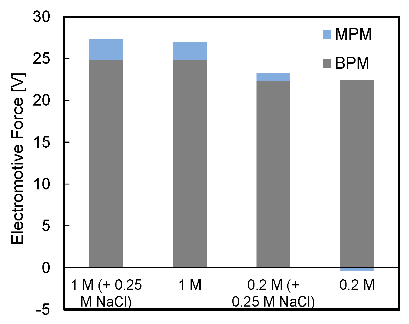
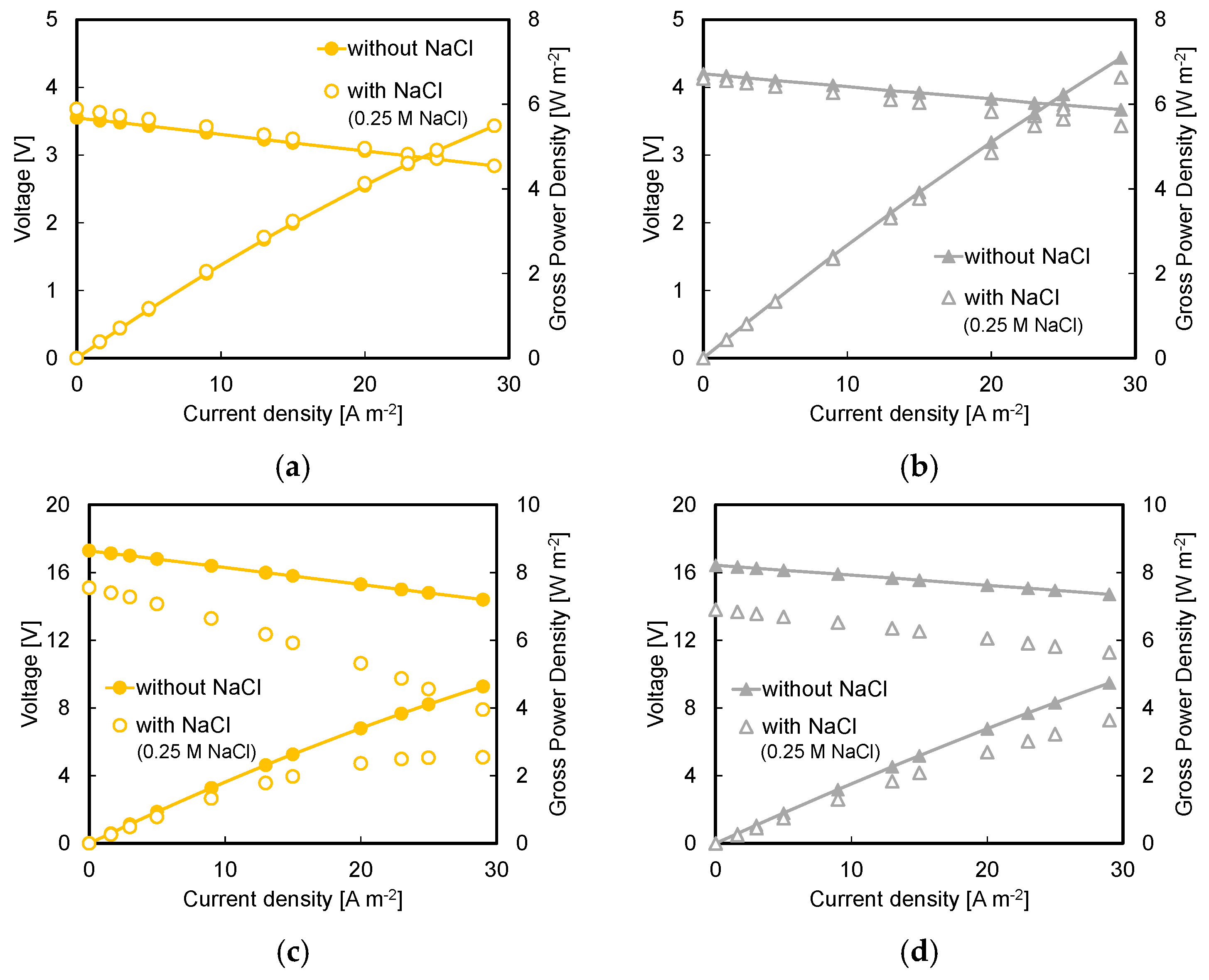
3.3. Effect of Background Salt in Acid and Base Streams

The presence of background NaCl in the acid and base streams was also investigated. This may be present in some waste streams as the acid mine drainage. More importantly, even in the case of “pure” waste streams (e.g., HCl and water only), co-ion leakages would bring salt in the acid and base channels, especially during industrial operations where long stack and/or solution recirculation are adopted to obtain complete neutralization. In other words, the presence of background salt in the acid and base channel should be regarded as an attempt to somehow mimic possible conditions during neutralization via BMRED at an industrial scale. The effect of the presence of salt as background concentration on the unit performance may be related to its influence on the electromotive force. Equation (1) shows that the EMF is the sum of the electric potential over the bipolar membrane, i.e., the first two addends, and over the monopolar membranes (MPMs), i.e., the last two addends (CEM and AEM contribution, respectively). The histogram in Figure 9 illustrates the EMF and its two contributions computed by Equation (1).
BPM contribution is predominant and depends on the acid and base concentrations only, regardless of the presence of NaCl as background. On the other hand, MPM contribution is dependent on both acid/base and salt concentrations. For instance, with HCl and NaOH concentrations equal to 1 M, the presence of background salt increases the EMF by ~1.3%. The lower the HCl/NaOH concentration, the higher is the effect of background salt. Particularly, with a HCl/NaOH concentration equal to 0.2 M, the background salt raises the EMF by ~5.4% with the MPMs contribution inverting from negative to positive.
The effect of the presence of salt as background concentration on the unit performance was found to depend on the number of triplets. Figure 10a,b show stack voltage and gross power density vs. external current curves related to a stack mounting five repeating units fed by either streams 0.2 M or 1 M as acid and base concentration also provided or not with 0.25 M NaCl (flow velocity = 1 cm s−1 in all cases).
The performances without NaCl are really similar to the ones with NaCl (0.25 M), although slightly lower GPDs are found for the cases with NaCl: in particular GPD at 29 A m−2 reached 1 M acid and base is found to reduce from 7 ± 0.1 to 6.6 ± 0.2 W m−2 when NaCl (0.25 M) is added to the acid/base streams. This detrimental effect is due to the lower resistance exhibited by the stack when no NaCl streams are fed in the acid and base channels. Since the conductivity of the solutions is higher when NaCl is added to HCl and NaOH solution, the higher stack resistance is supposed to be due to a higher IEMs resistance (associated to the lower mobility of Na+ and Cl ions compared to the one of protons and hydroxyls). When the number of triplets is higher (see Figure 10c,d), e.g., 30 triplets, the difference in the module performance is significant.
OCV was much lower when NaCl (0.25 M) was added to acid and base and the stack resistance was much higher, especially when HCl and NaOH concentration was low (e.g., 0.2 M as in Figure 10c). GPD at 29 A m−2 decreased from 4.7 ± 0.1 (without NaCl) to 3.6 ± 0.1 W m−2 for the case of 1 M as acid and base concentration, and from 4.6 ± 0.1 (without NaCl) to 2.5 ± 0.1 W m−2 for the 0.2 M case. It is worth noting that, extrapolating the GPD curve to higher current densities, the maximum power density would be reached with 1 M as acid and base solutions concentration, i.e., ~6 W m−2, considering that the lower measured OCV is compensated by a lower stack resistance and a higher electromotive force. At low concentrations of HCl and NaOH (e.g., 0.2 M), these phenomena are emphasized by the comparable concentration of salt ions and protons and hydroxyls. At high numbers of triplets, these effects add to the presence of parasitic currents, leading to even worse performances. This can be inferred from a comparison of Figure 4 with Figure 11 where OCV values in the presence of background NaCl in acid and base streams are shown as a function of the triplets number. Thus, NaCl addition to acid and base streams led to worse performances, probably due to accumulation of salt inside the BPM interlayer that can influence the Donnan potential of the CEL and AEL due to an increase in the membranes’ resistance because of the lower transport number of Na+ and Cl- compared to H+ and OH-. Clearly, further studies focused on these aspects are needed to validate the above hypotheses.

3.4. Energy Density and Perspective Cost Analysis

The energy density (energy extracted from a unit volume of processed solution(s)) is an important performance parameter for the neutralization process via BMRED. The gross energy density (i.e., neglecting the energy loss due to pumping), GED (kWh m−3), was estimated as the average gross power achievable over a complete neutralization of the pH gradient, divided by the flow rate fed to the acid compartment, multiplied by the number of sequential stages (through a longer stack and/or multiple stacks) as reported in Equation (6):
G E D = n   P ¯ Q × 3.6 × 10 6
where n is the number of sequential stages, Q is the total acid flow rate (in m3 s−1) and P ¯ is the average gross power calculated as follows:
P ¯ = C H C l , i n C H C l , f i n P   d C H C l C H C l , i n C H C l , f i n
where P is the gross power, CHCl,in and CHCl,fin are the initial and final hydrochloric acid concentration achieved in the whole neutralization process, respectively.
In particular, P was experimentally measured at different inlet concentrations, and thus at different inlet–outlet average concentrations (estimated by titration). The trend of the produced power as a function of the average concentration was experimentally obtained, either with or without the presence of background salt in the acid and base channels, and can be expressed with the following equation:
P = b 1   C H C l 2 + b 2   C H C l + b 3
where b1, b2 and b3 are the regression coefficients listed in Table 3.
The number of stages n is given by
n = C H C l , i n C H C l , f i n Δ C i n l o u t
where ΔCinl-out is the inlet–outlet mean concentration difference observed in a single passage during the experiments, reported in Table 3.
The experiments considered for the calculation of the GED regard a 10-cm-long stack provided with 10 triplets, fed at a fluid velocity of 1 cm s−1with 1 M acid and base initial concentration and with 0.25 M NaCl solution in the salt compartments. Two different conditions of current density were analyzed: (i) 29 A m−2 either with or without 0.25 M NaCl as background salt concentration in the acid and base channels, (ii) 100 A m−2 without NaCl as salt background. From the experimental results obtained under these conditions, a number of BMRED stages equal to 59 and 50 was calculated for the complete discharge ( C H C l , f i n = 0), either with or without the presence of salt in the acid and base streams, at a current density to 29 A m−2. Increasing the current density to 100 A m−2, the number of BMRED stages was 45. At a current density equal to 29 A m−2, the calculated values of GED were ~4.6 kWh m−3 and ~5.8 kWh m−3 (of acid) either with or without background salt, respectively. At a current density equal to 100 A m−2 the calculated value of GED was ~10.3 kWh m−3. These energy densities are on average one order of magnitude higher than the maximum values (free energy) extractable from the salinity gradient of the couple seawater/river water by employing a conventional RED process [67]. Moreover, the efficiency of the process η was evaluated as:
η = G E D G E D t h
in which GEDth is the theoretical energy density. It was calculated as follows:
G E D t h = F 10 7 C H C l E M F   d C H C l
and it is ~24 kWh m−3 at HCl and NaOH concentrations equal to 1 M. At a current density of 29 A m−2 the efficiencies were estimated to be ~19% and ~24% either with or without the background salt, respectively. This 5% decrease in the efficiency when salt is added is mainly due to the reduction of the membrane selectivity, as shown by the reduction of OCV reported in Section 3.3. At a current density equal to 100 A m−2, the efficiency was 43%. Furthermore, the electrical efficiency, calculated as the power delivered to the external load divided by the total (internal and external) dissipated power [63] was higher than 50% (which, instead, would occur at the maximum GPD) at 29 A m−2 due to the relative closeness to the open circuit condition. On the other hand, at 100 A m−2 the working point was relatively close to the maximum power density, thus resulting in a lower electrical efficiency, about 50%. Improvements in the components (mainly membranes) and the optimization of stack design and operating conditions can lead to better performance and must converge towards the best compromise between GPD and GED, which is eventually governed by economic aspects (maximum profit). Note that the above estimations do not take into account pressure losses. However, by assuming in the worst case an energy loss of 10% (according to the CFD correlation mentioned above) the computed efficiency decreases by 2% on average.
A perspective cost analysis was performed in order to evaluate the profitability of the energy recovery by BMRED. The present experimental results at 100 A m−2 were used for the economic calculations. The used parameters and the results of the cost analysis are reported in Table 4. It can be observed that the Levelized Cost Of Electricity (LCOE) [68] is 0.09 € kWh−1 in the scenario considered here. Thanks to the low cost of membranes considered for a future-based perspective (one order of magnitude lower than the current cost), especially for the BPMs, the process economics is satisfactory. Note that, however, this cost analysis was performed with the present experimental results, which are far from being optimal. Several improvements could enhance significantly the BMRED performance and thus the process profit, such as high-performance membranes, optimized stacks and operating conditions. Moreover, the use of more concentrated solutions could boost the recovered energy. For example, an increase of 50% in the GPD (from 13.7 to 20.6 W m−2), which can be expected in suitably designed stacks, would result in a LCOE of 0.06 € kWh−1. Furthermore, another important source of income may be a partial saving in the costs of treatment of solutions already neutralized by BMRED (instead of the complete treatment of acid and alkaline solutions). Therefore, practical applications of the BMRED technology could be prospected in the future, provided that the current bottleneck given by the membrane cost is overcome.

4. Conclusions

In this work, we presented the performances of a BMRED lab-scale module (provided with monopolar and bipolar exchange membranes) as a promising system to harvest energy from the neutralization of acid and base streams. Stack performances were investigated as a function of several process parameters, such as electrode rinse solution composition, acid and base streams composition, flow velocity inside the channels and number of repeating units, with once-through tests, showing promising results.
The following achievements can be derived from this study:
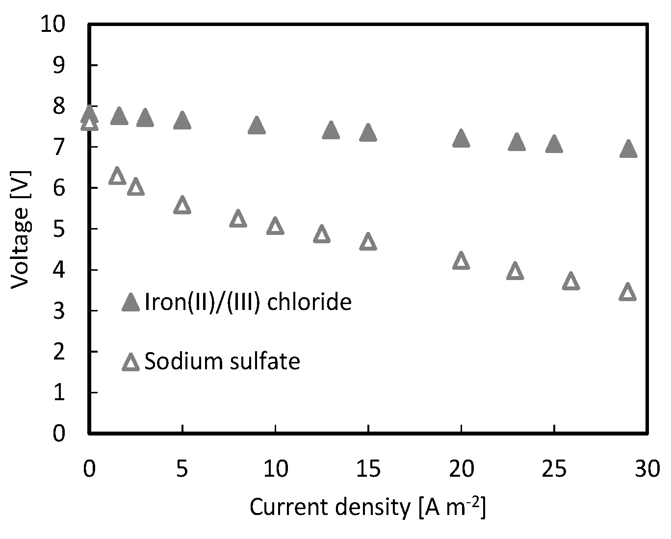
  • Electrode rinse solution composed of FeCl2/FeCl3 was found to guarantee lower voltage losses compared to Na2SO4 (Appendix A);
  • Higher available pH gradient allowed for higher power densities, due to the higher electromotive force and the lower stack resistance. Under the conservative value of current density of 29 A m−2, a power density of 7.1 W m−2 was reached for a stack with five repeating units fed by 1 M HCl and NaOH solutions;
  • A maximum power density of 17.4 W m−2 was reached at higher values of current density, i.e., 100 A m−2, with a 10-triplet stack and a flow velocity of 1 cm s−1;
  • Considering a current density value of 100 A m−2, a complete neutralization of the pH gradient would lead to an energy density higher than 10 kWh m−3 acid.
Further studies and special tailored membranes will be necessary to boost the technology development and promote its applicability. The process efficiency can be enhanced by developing high-performance membranes able to reduce co-ion leakage as much as possible and to bear higher current densities without damage (i.e., no delamination issues). In view of a process scale-up (i.e., larger units equipped with several repeating units), the stack should be designed with measures against parasitic currents, thus enabling the production of more power without loss in efficiency.
The behavior of the system could be also tested by feeding real acid/base wastewaters as the performance of the process might be strongly dependent on the composition of the waste solutions. Thus, the performance of BMRED technology should be analyzed case by case. In particular, the effect of other ions (multivalent included), their possible precipitation during pH variation, or even the presence of undesired organic foulants should be fully addressed and will be a matter for future studies.

Author Contributions

Conceptualization, A.T., A.Z., G.M. and M.S.; methodology, A.T., A.Z., G.M. and M.S.; validation, A.C. (Alessandro Cosenza), A.T., A.Z., L.G., M.S.; formal analysis, A.C. (Andrea Culcasi) and L.G.; investigation, A.C. (Alessandro Cosenza), and A.Z.; resources, A.T. and G.M.; visualization, A.Z., A.C. (Andrea Culcasi) and A.C. (Alessandro Cosenza), data curation, A.T., L.G. and A.Z.; writing—original draft preparation, A.Z.; writing—review and editing, A.C. (Andrea Culcasi), A.T., A.Z., L.G., G.M. and M.S.; supervision, A.T., G.M. and M.S.; project administration, A.T. and G.M.; funding acquisition, A.T. and G.M. All authors have read and agreed to the published version of the manuscript.

Funding

This work was performed in the framework of the BAoBaB project (Blue Acid/Base Battery: Storage and recovery of renewable electrical energy by reversible salt water dissociation). The BAoBaB project has received funding from the European Union’s Horizon 2020 Research and Innovation program under Grant Agreement no. 731187 (www.baobabproject.eu).

Conflicts of Interest

The authors declare no conflict of interest.

Nomenclature

Symbols
a [mol m−3]Ion activity
A [m2]Membrane area
C [mol l−1]Concentration
EMF [V]Electromotive Force
F [C mol−1]Faraday constant
GED [kWh m−3]Gross Energy Density
GPD [W m−2]Gross Power Density
I [A]Current
nNumber of stages
NNumber of triplets
NPD [W m−2]Net Power Density
P [W]Gross Power
Q [m3 s−1]Flow rate
Rg [J mol−1 K−1]Universal gas constant
R [Ω cm2]Resistance
T [K]Temperature
V [V]Voltage
zIon oxidation number
Greek letters
ΔDifference
φ [V]Electrical potential
αAverage apparent permselectivity
ηEfficiency
Subscripts/superscripts
acAcidic solution/CEL interface
appApparent
baAEL interface/Base solution
blankBlank
bpBipolar membrane interlayer
BPMBipolar membrane
extExternal
finFinal
iCell triplet
inInitial
inlInlet
manManifold
outOutlet
parParasitic
PumpPumping
saIEM/salt solution interfaces
StackStack
thTheoretical
Acronyms/abbreviations
AELAnion Exchange Layer
AEMAnion Exchange Membrane
BMEDBipolar Electrodialysis
BMREDBipolar Reverse Electrodialysis
BPMBipolar Membrane
CELCation Exchange Layer
CEMCation Exchange Membrane
CFDComputational Fluid Dynamics
DSADimensionally Stable Anode
EDElectrodialysis
EMFElectromotive Force
ERSElectrode Rinse Solution
GEDGross Energy Density
GPDGross Power Density
IECIon Exchange Capacity
IEMIon Exchange Membrane
MPMMonopolar Membrane
OCVOpen Circuit Voltage
REDReverse Electrodialysis
SGESalinity Gradient Energy

Appendix A

Effect of Electrode Rinse Solution Composition

Voltage vs. current density curves recorded using two different electrode rinse solutions (see Materials and Methods section) with a stack composed by 10 triplets fed with acid and base solutions 1 M (in HCl and NaOH, respectively) are shown in Figure A1.
Figure A1. Stack voltage vs. current density curve for a BMRED module with 10 triplets for the two electrode rinse solutions tested.
Energies 13 05510 g0a1
The measured OCV, i.e., 7.8 ± 0.15 V, was not dependent on the composition of ERS, but a significant difference in the stack performances was observed when a current flowed through the system. In fact, stack voltage values, in the case of Na2SO4 used as ERS, were lower than those recorded with the stack using FeCl2/FeCl3 aqueous solution. The voltage loss was more than 1 V, leading to a significant lower extractable power from the system. It is worth noting that this result is not dependent on the concentration of acid and base solutions but only on the composition of the ERS.
The difference in stack performances close to the OCV condition can be explained by considering the involved redox electrode reactions. In the case of Na2SO4, which was used as ERS in similar systems [54,55], the electrode reactions involve gaseous O2 and H2 evolution through water electrolysis corresponding to a difference of the redox couples potentials of 1.23 V. In addition, quite high overvoltages are needed for the H2 and O2 evolution reactions. This leads to larger voltage losses and, thus, to the worse performances shown in Figure A1, although using Na2SO4 as ERS has several advantages in terms of high stability, low toxicity and cheapness [59,70]. Moreover, this solution imposes the correct handling of the ERS to avoid the formation of an explosive mixture.
In the case of FeCl2/FeCl3 aqueous solution used as ERS, the electrode reactions involve the oxidation of Fe2+ to Fe3+ at the anode and the reverse reaction at the cathode. These reactions need very low overvoltage and do not involve gas production; thus, they are very suitable for this system, even if the pH solution must be continuously checked (high values of pH must be avoided to prevent iron oxy-hydroxide precipitation) and the disposal of this acidic ERS could be an issue [59].
Therefore, for all the experiments we used the FeCl2/FeCl3 couple, which represents the best trade-off among the reasons mentioned above.

References

  1. Goel, R.K.; Flora, J.R.V.; Chen, J.P. Flow Equalization and Neutralization. In Handbook of Environmental Engineering, Volume 3: Physicochemical Treatment Processes; Wang, L.K., Hung, Y.-T., Shammas, N.K., Eds.; The Humana Press Inc.: Totowa, NJ, USA, 2005; pp. 21–45. [Google Scholar]
  2. Kesieme, U.; Chrysanthou, A.; Catulli, M.; Cheng, C.Y. A review of acid recovery from acidic mining waste solutions using solvent extraction. J. Chem. Technol. Biotechnol. 2018, 93, 3374–3385. [Google Scholar] [CrossRef] [Green Version]
  3. Culcasi, A.; Gueccia, R.; Randazzo, S.; Cipollina, A.; Micale, G. Design of a novel membrane-integrated waste acid recovery process from pickling solution. J. Clean. Prod. 2019, 236, 117623. [Google Scholar] [CrossRef]
  4. Gurreri, L.; Cipollina, A.; Tamburini, A.; Micale, G. Electrodialysis for wastewater treatment—Part II: Industrial effluents. In Current Trends and Future Developments in Bio-Membranes: Membrane Technology for Water and Wastewater Treatment—Advances and Emerging Processes; Basile, A., Comite, A., Eds.; Elsevier: Amsterdam, The Netherlands, 2020; pp. 195–241. [Google Scholar]
  5. Gurreri, L.; Tamburini, A.; Cipollina, A.; Micale, G. Electrodialysis Applications in Wastewater Treatment for Environmental Protection and Resources Recovery: A Systematic Review on Progress and Perspectives. Membranes 2020, 10, 146. [Google Scholar] [CrossRef] [PubMed]
  6. Tansens, P.; Rodal, A.T.; Machado, C.M.; Soares, H.M. Recycling of aluminum and caustic soda solution from waste effluents generated during the cleaning of the extruder matrixes of the aluminum industry. J. Hazard. Mater. 2011, 187, 459–465. [Google Scholar] [CrossRef] [PubMed]
  7. Aprea, P.; De Gennaro, B.; Colella, C. An unconventional method for the recovery of caustic soda from spent Al-rich pickling solutions. J. Environ. Manag. 2011, 92, 1821–1827. [Google Scholar] [CrossRef] [PubMed]
  8. Rahman, A.; Khan, N.E. Study of an Evaporation System for Sodium Hydroxide Solution. J. Chem. Eng. 2006, 24, 35–36. [Google Scholar] [CrossRef] [Green Version]
  9. Ben Hariz, I.; Halleb, A.; Adhoum, N.; Monser, L. Treatment of petroleum refinery sulfidic spent caustic wastes by electrocoagulation. Sep. Purif. Technol. 2013, 107, 150–157. [Google Scholar] [CrossRef]
  10. Imran, B.; Khan, S.J.; Qazi, I.A.; Arshad, M. Removal and recovery of sodium hydroxide (NaOH) from industrial wastewater by two-stage diffusion dialysis (DD) and electrodialysis (ED) processes. Desalin. Water Treat. 2016, 57, 7926–7932. [Google Scholar] [CrossRef]
  11. Sarkar, S.; Sengupta, A.K.; Greenleaf, J.E.; El-Moselhy, M. Energy Recovery from Acid–Base Neutralization Process through pH-Sensitive Polymeric Ion Exchangers. Ind. Eng. Chem. Res. 2011, 50, 12293–12298. [Google Scholar] [CrossRef]
  12. German, M.; Sengupta, A.K.; Greenleaf, J. Hydrogen Ion (H+) in Waste Acid as a Driver for Environmentally Sustainable Processes: Opportunities and Challenges. Environ. Sci. Technol. 2013, 47, 2145–2150. [Google Scholar] [CrossRef]
  13. Zhu, X.; Yang, W.; Hatzell, M.C.; Logan, B.E. Energy Recovery from Solutions with Different Salinities Based on Swelling and Shrinking of Hydrogels. Environ. Sci. Technol. 2014, 48, 7157–7163. [Google Scholar] [CrossRef] [PubMed]
  14. Facci, T.; Gomes, W.J.A.S.; Bravin, B.; Araújo, D.M.; Huguenin, F. Proton Electroinsertion in Self-Assembled Materials for Neutralization Pseudocapacitors. Langmuir 2014, 30, 426–431. [Google Scholar] [CrossRef] [PubMed]
  15. Pattle, R.E. Production of Electric Power by mixing Fresh and Salt Water in the Hydroelectric Pile. Nature 1954, 174, 660. [Google Scholar] [CrossRef]
  16. Logan, B.E.; Elimelech, M. Membrane-based processes for sustainable power generation using water. Nature 2012, 488, 313–319. [Google Scholar] [CrossRef]
  17. Hong, J.G.; Zhang, B.; Glabman, S.; Uzal, N.; Dou, X.; Zhang, H.; Wei, X.; Chen, Y. Potential ion exchange membranes and system performance in reverse electrodialysis for power generation: A review. J. Membr. Sci. 2015, 486, 71–88. [Google Scholar] [CrossRef]
  18. Alvarez-Silva, O.A.; Osorio, A.F.; Winter, C. Practical global salinity gradient energy potential. Renew. Sustain. Energy Rev. 2016, 60, 1387–1395. [Google Scholar] [CrossRef]
  19. Geise, G.M.; Curtis, A.J.; Hatzell, M.C.; Hickner, M.A.; Logan, B.E. Salt Concentration Differences Alter Membrane Resistance in Reverse Electrodialysis Stacks. Environ. Sci. Technol. Lett. 2014, 1, 36–39. [Google Scholar] [CrossRef]
  20. Daniilidis, A.; Vermaas, D.A.; Herber, R.; Nijmeijer, K. Experimentally obtainable energy from mixing river water, seawater or brines with reverse electrodialysis. Renew. Energy 2014, 64, 123–131. [Google Scholar] [CrossRef]
  21. Tedesco, M.; Cipollina, A.; Tamburini, A.; Micale, G. Towards 1 kW power production in a reverse electrodialysis pilot plant with saline waters and concentrated brines. J. Membr. Sci. 2017, 522, 226–236. [Google Scholar] [CrossRef] [Green Version]
  22. Avci, A.H.; Tufa, R.A.; Fontananova, E.; Di Profio, G.; Curcio, E. Reverse Electrodialysis for energy production from natural river water and seawater. Energy 2018, 165, 512–521. [Google Scholar] [CrossRef]
  23. Ortiz-Martínez, V.M.; Gómez-Coma, L.; Tristán, C.; Pérez, G.; Fallanza, M.; Ortiz, A.; Ibañez, R.; Ortiz, I. A comprehensive study on the effects of operation variables on reverse electrodialysis performance. Desalination 2020, 482, 114389. [Google Scholar] [CrossRef]
  24. Long, R.; Kuang, Z.; Liu, Z.; Liu, W. Ionic thermal up-diffusion in nanofluidic salinity-gradient energy harvesting. Natl. Sci. Rev. 2019, 6, 1266–1273. [Google Scholar] [CrossRef]
  25. Long, R.; Luo, Z.; Kuang, Z.; Liu, Z.; Liu, W. Effects of heat transfer and the membrane thermal conductivity on the thermally nanofluidic salinity gradient energy conversion. Nano Energy 2020, 67, 104284. [Google Scholar] [CrossRef]
  26. Veerman, J.; Saakes, M.; Metz, S.J.; Harmsen, G.J. Electrical Power from Sea and River Water by Reverse Electrodialysis: A First Step from the Laboratory to a Real Power Plant. Environ. Sci. Technol. 2010, 44, 9207–9212. [Google Scholar] [CrossRef] [PubMed]
  27. Vermaas, D.A.; Veerman, J.; Yip, N.Y.; Elimelech, M.; Saakes, M.; Nijmeijer, K. High Efficiency in Energy Generation from Salinity Gradients with Reverse Electrodialysis. ACS Sustain. Chem. Eng. 2013, 1, 1295–1302. [Google Scholar] [CrossRef]
  28. Hu, J.; Xu, S.; Wu, X.; Wu, D.; Jin, D.; Wang, P.; Leng, Q. Multi-stage reverse electrodialysis: Strategies to harvest salinity gradient energy. Energy Convers. Manag. 2019, 183, 803–815. [Google Scholar] [CrossRef]
  29. Giacalone, F.; Vassallo, F.; Scargiali, F.; Tamburini, A.; Cipollina, A.; Micale, G. The first operating thermolytic reverse electrodialysis heat engine. J. Membr. Sci. 2020, 595, 117522. [Google Scholar] [CrossRef]
  30. Veerman, J.; De Jong, R.M.; Saakes, M.; Metz, S.J.; Harmsen, G.J. Reverse electrodialysis: Comparison of six commercial membrane pairs on the thermodynamic efficiency and power density. J. Membr. Sci. 2009, 343, 7–15. [Google Scholar] [CrossRef]
  31. Długołęcki, P.; Ogonowski, P.; Metz, S.J.; Saakes, M.; Nijmeijer, K.; Wessling, M. On the resistances of membrane, diffusion boundary layer and double layer in ion exchange membrane transport. J. Membr. Sci. 2010, 349, 369–379. [Google Scholar] [CrossRef]
  32. Nikonenko, V.; Nebavsky, A.; Mareev, S.; Kovalenko, A.; Urtenov, M.; Pourcelly, G. Modelling of Ion Transport in Electromembrane Systems: Impacts of Membrane Bulk and Surface Heterogeneity. Appl. Sci. 2018, 9, 25. [Google Scholar] [CrossRef] [Green Version]
  33. Kozaderova, O.A.; Kim, K.B.; Gadzhiyeva, C.S.; Niftaliev, S.I. Electrochemical characteristics of thin heterogeneous ion exchange membranes. J. Membr. Sci. 2020, 604, 118081. [Google Scholar] [CrossRef]
  34. Ma, P.; Hao, X.; Galia, A.; Scialdone, O. Development of a process for the treatment of synthetic wastewater without energy inputs using the salinity gradient of wastewaters and a reverse electrodialysis stack. Chemosphere 2020, 248, 125994. [Google Scholar] [CrossRef] [PubMed]
  35. Di Salvo, J.L.; Cosenza, A.; Tamburini, A.; Micale, G.; Cipollina, A. Long-run operation of a reverse electrodialysis system fed with wastewaters. J. Environ. Manag. 2018, 217, 871–887. [Google Scholar] [CrossRef]
  36. Kingsbury, R.S.; Liu, F.; Zhu, S.; Boggs, C.; Armstrong, M.D.; Call, D.F.; Coronell, O. Impact of natural organic matter and inorganic solutes on energy recovery from five real salinity gradients using reverse electrodialysis. J. Membr. Sci. 2017, 541, 621–632. [Google Scholar] [CrossRef]
  37. Hatzell, M.C.; Zhu, X.; Logan, B.E. Simultaneous Hydrogen Generation and Waste Acid Neutralization in a Reverse Electrodialysis System. ACS Sustain. Chem. Eng. 2014, 2, 2211–2216. [Google Scholar] [CrossRef]
  38. Güler, E.; Zhang, Y.; Saakes, M.; Nijmeijer, K. Tailor-Made Anion-Exchange Membranes for Salinity Gradient Power Generation Using Reverse Electrodialysis. ChemSusChem 2012, 5, 2262–2270. [Google Scholar] [CrossRef]
  39. Mikhaylin, S.; Bazinet, L. Fouling on ion-exchange membranes: Classification, characterization and strategies of prevention and control. Adv. Colloid Interface Sci. 2016, 229, 34–56. [Google Scholar] [CrossRef] [PubMed]
  40. Gómez-Coma, L.; Ortiz-Martínez, V.M.; Carmona, J.; Palacio, L.; Prádanos, P.; Fallanza, M.; Ortiz, A.; Ibañez, R.; Ortiz, I. Modeling the influence of divalent ions on membrane resistance and electric power in reverse electrodialysis. J. Membr. Sci. 2019, 592, 117385. [Google Scholar] [CrossRef]
  41. Besha, A.T.; Tsehaye, M.T.; Aili, D.; Zhang, W.; Tufa, R.A. Design of Monovalent Ion Selective Membranes for Reducing the Impacts of Multivalent Ions in Reverse Electrodialysis. Membranes 2019, 10, 7. [Google Scholar] [CrossRef] [Green Version]
  42. Merino-Garcia, I.; Kotoka, F.; Portugal, C.A.M.; Crespo, J.G.; Velizarov, S. Characterization of Poly (Acrylic) Acid-Modified Heterogenous Anion Exchange Membranes with Improved Monovalent Permselectivity for RED. Membranes 2020, 10, 134. [Google Scholar] [CrossRef]
  43. Kotoka, F.; Merino-Garcia, I.; Velizarov, S. Surface Modifications of Anion Exchange Membranes for an Improved Reverse Electrodialysis Process Performance: A Review. Membranes 2020, 10, 160. [Google Scholar] [CrossRef]
  44. Mei, Y.; Liu, L.; Lu, Y.-C.; Tang, C.Y. Reverse Electrodialysis Chemical Cell for Energy Harvesting from Controlled Acid–Base Neutralization. Environ. Sci. Technol. 2019, 53, 4640–4647. [Google Scholar] [CrossRef] [PubMed]
  45. Huang, C.; Xu, T. Electrodialysis with Bipolar Membranes for Sustainable Development. Environ. Sci. Technol. 2006, 40, 5233–5243. [Google Scholar] [CrossRef] [PubMed]
  46. Strathmann, H. Electrodialysis, a mature technology with a multitude of new applications. Desalination 2010, 264, 268–288. [Google Scholar] [CrossRef]
  47. Thiel, G.P.; Kumar, A.; Gómez-González, A.; Lienhard, J.H. Utilization of Desalination Brine for Sodium Hydroxide Production: Technologies, Engineering Principles, Recovery Limits, and Future Directions. ACS Sustain. Chem. Eng. 2017, 5, 11147–11162. [Google Scholar] [CrossRef]
  48. Zhang, X.; Wang, X.; Chen, Q.; Lv, Y.; Han, X.; Wei, Y.; Xu, T. Batch Preparation of High Basicity Polyferric Sulfate by Hydroxide Substitution from Bipolar Membrane Electrodialysis. ACS Sustain. Chem. Eng. 2017, 5, 2292–2301. [Google Scholar] [CrossRef]
  49. Herrero-Gonzalez, M.; Diaz-Guridi, P.; Dominguez-Ramos, A.; Irabien, A.; Ibañez, R. Highly concentrated HCl and NaOH from brines using electrodialysis with bipolar membranes. Sep. Purif. Technol. 2020, 242, 116785. [Google Scholar] [CrossRef]
  50. Ramírez, P.; Rapp, H.-J.; Mafé, S.; Bauer, B. Bipolar membranes under forward and reverse bias conditions. Theory vs. experiment. J. Electroanal. Chem. 1994, 375, 101–108. [Google Scholar] [CrossRef]
  51. Pretz, J.; Staude, E. Reverse electrodialysis (RED) with bipolar membranes, an energy storage system. Ber. Bunsenges. Phys. Chem. 1998, 102, 676–685. [Google Scholar] [CrossRef]
  52. Zholkovskij, E.K.; Müller, M.C.; Staude, E. The storage battery with bipolar membranes. J. Membr. Sci. 1998, 141, 231–243. [Google Scholar] [CrossRef]
  53. Kim, J.-H.; Lee, J.-H.; Maurya, S.; Shin, S.-H.; Lee, J.Y.; Chang, I.S.; Moon, S.-H. Proof-of-concept experiments of an acid-base junction flow battery by reverse bipolar electrodialysis for an energy conversion system. Electrochem. Commun. 2016, 72, 157–161. [Google Scholar] [CrossRef]
  54. Van Egmond, W.J.; Saakes, M.; Noor, I.; Porada, S.; Buisman, C.J.N.N.; Hamelers, H.V.M. Performance of an environmentally benign acid base flow battery at high energy density. Int. J. Energy Res. 2018, 42, 1524–1535. [Google Scholar] [CrossRef] [Green Version]
  55. Xia, J.; Eigenberger, G.; Strathmann, H.; Nieken, U. Flow battery based on reverse electrodialysis with bipolar membranes: Single cell experiments. J. Membr. Sci. 2018, 565, 157–168. [Google Scholar] [CrossRef]
  56. Xia, J.; Eigenberger, G.; Strathmann, H.; Nieken, U. Acid-Base Flow Battery, Based on Reverse Electrodialysis with Bi-Polar Membranes: Stack Experiments. Processes 2020, 8, 99. [Google Scholar] [CrossRef] [Green Version]
  57. Culcasi, A.; Gurreri, L.; Zaffora, A.; Cosenza, A.; Tamburini, A.; Micale, G. On the modelling of an Acid/Base Flow Battery: An innovative electrical energy storage device based on pH and salinity gradients. Appl. Energy 2020, 277, 115576. [Google Scholar] [CrossRef]
  58. Gurreri, L.; Tamburini, A.; Cipollina, A.; Micale, G.; Ciofalo, M. Pressure drop at low Reynolds numbers in woven-spacer-filled channels for membrane processes: CFD prediction and experimental validation. Desalin. Water Treat. 2017, 61, 170–182. [Google Scholar] [CrossRef] [Green Version]
  59. Veerman, J.; Saakes, M.; Metz, S.J.; Harmsen, G.J. Reverse electrodialysis: Evaluation of suitable electrode systems. J. Appl. Electrochem. 2010, 40, 1461–1474. [Google Scholar] [CrossRef] [Green Version]
  60. Tedesco, M.; Brauns, E.; Cipollina, A.; Micale, G.; Modica, P.; Russo, G.; Helsen, J. Reverse electrodialysis with saline waters and concentrated brines: A laboratory investigation towards technology scale-up. J. Membr. Sci. 2015, 492, 9–20. [Google Scholar] [CrossRef] [Green Version]
  61. Culcasi, A.; Gurreri, L.; Zaffora, A.; Cosenza, A.; Tamburini, A.; Cipollina, A.; Micale, G. Ionic shortcut currents via manifolds in reverse electrodialysis stacks. Desalination 2020, 485, 114450. [Google Scholar] [CrossRef]
  62. Rubinstein, I.; Pretz, J.; Staude, E. Open circuit voltage in a reverse electrodialysis cell. Phys. Chem. Chem. Phys. 2001, 3, 1666–1667. [Google Scholar] [CrossRef]
  63. Veerman, J.; Post, J.W.; Saakes, M.; Metz, S.J.; Harmsen, G.J. Reducing power losses caused by ionic shortcut currents in reverse electrodialysis stacks by a validated model. J. Membr. Sci. 2008, 310, 418–430. [Google Scholar] [CrossRef] [Green Version]
  64. Tedesco, M.; Cipollina, A.; Tamburini, A.; Bogle, I.D.L.; Micale, G. A simulation tool for analysis and design of reverse electrodialysis using concentrated brines. Chem. Eng. Res. Des. 2015, 93, 441–456. [Google Scholar] [CrossRef] [Green Version]
  65. Ciofalo, M.; La Cerva, M.; Di Liberto, M.; Gurreri, L.; Cipollina, A.; Micale, G. Optimization of net power density in Reverse Electrodialysis. Energy 2019, 181, 576–588. [Google Scholar] [CrossRef]
  66. Nam, J.-Y.; Hwang, K.-S.; Kim, H.-C.; Jeong, H.; Kim, H.; Jwa, E.; Yang, S.C.; Choi, J.; Kim, C.-S.; Han, J.-H.; et al. Assessing the behavior of the feed-water constituents of a pilot-scale 1000-cell-pair reverse electrodialysis with seawater and municipal wastewater effluent. Water Res. 2019, 148, 261–271. [Google Scholar] [CrossRef] [PubMed]
  67. Veerman, J.; Saakes, M.; Metz, S.J.; Harmsen, G.J. Reverse electrodialysis: Performance of a stack with 50 cells on the mixing of sea and river water. J. Membr. Sci. 2009, 327, 136–144. [Google Scholar] [CrossRef] [Green Version]
  68. Giacalone, F.; Papapetrou, M.; Kosmadakis, G.; Tamburini, A.; Micale, G.; Cipollina, A. Application of reverse electrodialysis to site-specific types of saline solutions: A techno-economic assessment. Energy 2019, 181, 532–547. [Google Scholar] [CrossRef]
  69. Strathmann, H. Ion-Exchange Membrane Separation Processes, 1st ed.; Elsevier: Amsterdam, The Netherlands, 2004; Volume 9. [Google Scholar]
  70. Scialdone, O.; Albanese, A.; D’Angelo, A.; Galia, A.; Guarisco, C. Investigation of electrode material—Redox couple systems for reverse electrodialysis processes. Part II: Experiments in a stack with 10–50 cell pairs. J. Electroanal. Chem. 2013, 704, 1–9. [Google Scholar] [CrossRef]
Figure 1. Scheme of an entire Bipolar Membrane Reverse Electrodialysis (BMRED) module (with 5 repeating units, acid: HCl, base: NaOH). The inset on the right bottom shows an enlarged view of the repeating unit (triplet) with an additional anion-exchange membrane (AEM) along with the ions and water main fluxes. Right top inset: cross-flow configuration used in this work.
Energies 13 05510 g001
Figure 2. (a) Stack voltage and (b) gross power density curves for a BMRED unit with 10 triplets fed at 1 cm s−1 as a function of acid and base solutions inlet concentration.
Energies 13 05510 g002
Figure 3. (a) Stack voltage and (b) gross power density (with extrapolation at higher current densities) curves for a BMRED unit with 5 and 38 triplets fed at 1 cm s−1. Acid and base solutions inlet concentration = 0.6 M.
Energies 13 05510 g003
Figure 4. Open Circuit Voltage values for BMRED stacks as a function of number of triplets for different acid and base inlet concentrations (flow velocity = 1 cm s−1). Dashed lines: dependence of EMF (estimated according to Equation (1)) on the number of triplets.
Energies 13 05510 g004
Figure 5. (a) Stack voltage and (b) gross power density (with extrapolation at higher current densities) curves for a BMRED unit with 38 triplets as functions of the current density for different acid and base solutions inlet concentrations (flow velocity = 1 cm s−1).
Energies 13 05510 g005
Figure 6. (a) Apparent resistance of N triplets (Rapp) and (b) of 1 triplet (Rapp/N) as functions of the number of triplets (N) for all the tested acid and base inlet concentrations tested.
Energies 13 05510 g006
Figure 7. Simplified BMRED equivalent electric scheme.
Energies 13 05510 g007
Figure 8. Stack voltage curves for a BMRED unit with 20 triplets fed with (a) 0.2 M and 0.6 M and (b) 1 M acid and base streams as a function of the flow velocity inside the channel.
Energies 13 05510 g008
Figure 9. EMF contributions for a 30-triplet stack. Grey and blue areas refer to bipolar membrane (BPM) and monopolar membrane (MPM) contributions, respectively. Inlet concentrations: 0.2 M and 1 M HCl/NaOH with and without the presence of 0.25 M NaCl of background salt in the acid and base compartments. Salt stream: 0.25 M NaCl.
Energies 13 05510 g009
Figure 10. Stack voltage and gross power density curves for a BMRED unit with 5 triplets fed with (a) 0.2 M and (b) 1 M acid and base streams, and for a BMRED unit with 30 triplets fed with (c) 0.2 M and (d) 1 M acid and base streams. Empty symbols: 0.25 M NaCl as background salt concentration; solid symbols: no background salt.
Energies 13 05510 g010
Figure 11. Open Circuit Voltage values for BMRED stacks as a function of number of triplets for different acid and base inlet concentrations (flow velocity = 1 cm s−1) with NaCl 0.25 M as background salt concentration in the acid and base solutions. Dashed lines: dependence of EMF (estimated according to Equation (2)) on the number of triplets.
Energies 13 05510 g011
Table 1. Overview of literature data on BMRED systems.
AuthorsNumber of Repeating UnitsAcid/Base Concentration RangeEnergyPowerRefs.
Pretz and Staude2–200.1–1 M-10.9 W m−2[51]
Zholkovskij et al.40.03 M0.1 Wh kg−10.005 W kg−1[52]
Kim et al.10.1–0.7 M-6.6–11.6 W m−2[53]
Van Egmond et al.10–1 M2.9 Wh kg−13.7 W m−2[54]
Xia et al.1–200–1 M-16 W m−2[55,56]
Table 2. Physical and chemical properties of the Ion Exchange Membranes (IEMs) provided by manufacturer (n.p. means not provided).
NameTypeReinforcementThickness
(µm)
IEC
(meq g−1)
Selectivity
(%)
Areal Resistance
(Ω cm2)
pH
Stability
FABAnionPEEK100–1301.0–1.194–974–71–14
FKBCationPEEK100–1301.2–1.398–994–61–14
FBMBipolarPEEK180–200n.p.n.p.n.p.1–14
Table 3. Inputs for the energy density calculations: list of the P regression coefficients.
i (A m−2)ΔCinl-out b1b2b3
290.02 Mwith salt−1.011.761.11
290.017 Mwithout salt00.501.51
1000.022 Mwithout salt−3.006.251.96
Table 4. Perspective economic analysis of the BMRED process.
ItemsValueNotes
BMRED system
Fluid velocity1 cm s−1
Membrane area0.1 × 0.1 m2
Channel thickness500 μm
Number of triplets per stage10
Number of stages45
GED (average GPD)10.3 kWh m−3 (13.7 W m−2)
Working hours8000 h y−1It corresponds to a capacity factor of ~90% [68]
Membrane life-time3 y
Investment and operating cost
AEM/CEM cost4 € m−2[68]
BPM cost20 € m−25 × AEM/CEM cost
Total membrane cost126 €
Cost of stacks (including membranes)189 €1.5 × total membrane cost [69]
Cost of peripherals95 €0.5 × stacks cost [69]
Capital cost284 €Stacks + peripheral costs [69]
Maintenance28.4 € y−10.1 × capital cost [69]
Economic parameters
Discount rate5%[68]
Outcome
LCOE0.09 € kWh−1
Publisher’s Note: MDPI stays neutral with regard to jurisdictional claims in published maps and institutional affiliations.

