Article

Model Predictive Control for Virtual Synchronous Generator with Improved Vector Selection and Reconstructed Current

1
School of Electrical and Information Engineering, Zhengzhou University of Light Industry, Zhengzhou 450000, China
2
College of Electrical and Information Engineering, Hunan University, Changsha 410082, China
*
Author to whom correspondence should be addressed.
Energies 2020, 13(20), 5435; https://doi.org/10.3390/en13205435
Submission received: 16 September 2020 / Revised: 14 October 2020 / Accepted: 15 October 2020 / Published: 18 October 2020
(This article belongs to the Special Issue Advanced Control Design and Fault Diagnosis)

Abstract

:
Due to the large-scale renewable energy connected to the power grid by power electronic converters, the inertia and stability of the power grid is declining. In order to improve the inertia and support the grid recovery, the three-phase converter works as a virtual synchronous generator (VSG) to respond to the frequency and voltage changes of the power grid. This paper proposes a model predictive control for the virtual synchronous generator (MPC-VSG) strategy, which can automatically control the converter output power with the grid frequency and voltage changes. Further consideration of fault-tolerant ability and reliability, the method based on improved voltage vector selection, and reconstructed current is used for MPC-VSG to ensure continuous operation for three-phase converters that have current-sensor faults, and improve the reconstruction precision. The proposed method can respond to the frequency and voltage changes of the power grid and has fault-tolerant ability, which is easy to realize without pulse width modulation (PWM) and a proportional-integral (PI) controller. The effectiveness of the proposed control strategy is verified by experiment.

Graphical Abstract

1. Introduction

The three-phase converter is applied widely in renewable energy power generation [1,2]. As the connection between renewable energy and the power grid, the converters controlled by conventional power decoupling cannot respond to the grid frequency and voltage changes due to lack of connection with the frequency and voltage of the grid. With the high penetration of large-scale renewable energy into the power grid, the inertia and stability of the power grid are declining. Hence, it is necessary to improve the inertial response capability of the three-phase converter.
By simulating the characteristics of the traditional synchronous generator (SG), the converter under the control of a virtual synchronous generator (VSG) can change the output power alone, with the frequency or voltage providing inertial support for the power grid [3,4]. Compared with conventional droop control, the grid-connected converter controlled by VSG has better dynamic characteristics and inertial response capability [5,6]. The VSG has been used in storage system, wind turbine, micro-grid, and multi-terminal high-voltage direct current (MTDC) systems to improve the inertia and stability of power grids [7,8,9,10,11]. A hybrid energy storage system (HESS) consisting of a battery and an ultra-capacitor is proposed in [7] to achieve the power management of the VSG, which allows reduction of the battery power fluctuations. The VSG-controlled doubly-fed induction generator (DFIG) is investigated in [8] to provide the desired inertial support to the power grid. A comprehensive VSG control method is proposed in [10] for the full converter of wind turbines with energy storage, and the power balance of the wind turbine system is achieved. An extended VSG is introduced in [9] for a micro-grid. The virtual controller combines the virtual rotor, virtual primary, and virtual secondary control to regulate the system frequency. A VSG control strategy is proposed in [11], using MTDC to damp the low-frequency oscillation. The rotational inertia part and governor part are both controlled by VSG. The parameters for VSG are constrained by stability considerations and transfer function analysis is validated in [12]. In addition to the application of VSG research, the expansion and fault-tolerant of VSG need to be further studied.
Model predictive control (MPC) has attracted researchers’ interest recently, due to the advantages of flexibility, strong robustness, and simple implementation. Without pulse width modulation (PWM), phase-locked loop (PLL), or a proportional–integral (PI) or proportion resonant (PR) controller, the MPC outputs the optimal switching state of the converter by comparing the predictive and reference values with the cost function [13,14]. The MPC has been used in quasi-Z-source inverters, three-phase inverters, rectifier–inverter systems, multilevel converters, wind turbine systems, and three-phase soft-switching converters [15,16,17,18,19,20]. A discrete-time average model-based predictive control (DTA-MPC) is proposed in [15] for a quasi-Z-source inverter to predict future behaviors of the shoot-through duty cycle and modulation signals. A disturbance rejection-based MPC with two flexible modes for three-phase inverters is investigated and a disturbance observer is designed to simplify the prediction model in [16]. To address the dc-link voltage fluctuation, an improved MPC scheme is proposed for the PWM rectifier –inverter system in [17] based on the system-level power balance model. The MPC proposed in [18] divides variables into layers to reduce the number of states, and a method for compensating the distortion is also described. For a permanent-magnet synchronous generator (PMSG) wind turbine system, a multiple-vector direct model predictive power control is proposed in [19] for the grid-side power converter to improve the steady-state control performance. A robust constant-frequency model-predictive control proposed in [20] can reduce the total harmonic distortion under the unbalanced grid condition. The effectiveness of MPC has been verified with good performance, which is better than traditional PWM vector control [21,22]. However, the converter controlled by conventional MPC cannot respond to the power grid changes and provide inertial support.
The fault-tolerant research for the three-phase converter is necessary to improve the operation reliability. The reliability of the current sensor is essential for a grid-connected converter because the current signals sampled by current sensors influence the control performance directly. Current reconstruction can rebuild the three-phase current with fewer current sensors, which is an effective way to improve system reliability [23,24]. The current reconstruction has been used in switched reluctance motors (SRM), three-level converters, and permanent-magnet synchronous motors (PMSM) [25,26,27,28]. A phase current reconstruction method from the dc-link current is proposed in [25] for four-phase 8/6-pole SRM and confirmed by experimental results. A space vector PWM scheme to reconstruct phase currents is proposed in [26] for three-level T-type converters by using neutral-point current sensing. A zero-voltage vector sampling method (ZVVSM) is proposed in [28] for PMSM vector control system without modifying the PWM signal. The above current reconstruction methods are based on PWM and need to sample multiple points in one period. The easy way to reconstruct current for MPC needs to be researched.
This paper proposes a model predictive control for VSG (MPC-VSG) with reconstructed current considering inertial support for the power grid and fault-tolerant operation. The three-phase current is reconstructed by dc current and standard ac current under the control of improved voltage vector selection. The VSG is used to respond to grid changes and offers a reference current. The MPC generates the predictive current of the next instant in different voltage vectors. The voltage vector that makes the cost function minimal is the optimal vector. Then the corresponding switching states are applied for the converter. The main contributions of this paper are as follows:
(1)
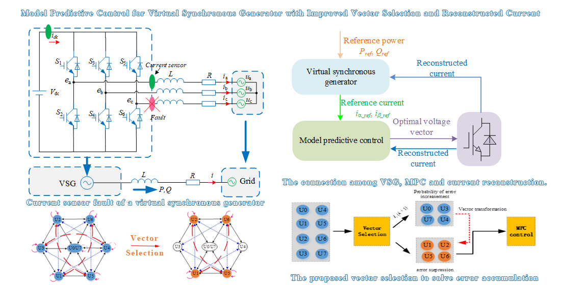
The MPC method is applied to VSG control to achieve the effectiveness control of the three-phase converter and improve the response capability for changes of grid frequency and voltage, which is flexible and simple without PWM and a PI controller.
(2)
The reconstructed current, based on the relationship of the dc current, ac current, and the voltage vectors, is used for MPC-VSG, which needs less current sensors and improves the fault-tolerant capability of the three-phase converter.
(3)
In order to improve the accuracy of current reconstruction, an improved voltage selection method is proposed for MPC-VSG, which can reduce the error of current reconstruction.
The three-phase converter controlled by the proposed MPC-VSG method can automatically adjust the output power according to the frequency and voltage of the power grid, and realize fault-tolerant operation under phase current-sensor fault. The effectiveness of the proposed method is verified by experimental results.

2. Models of VSG, MPC, and Current Reconstruction

The combination of VSG and MPC is used in this paper to achieve participation in the frequency and voltage regulation of the power grid and keep the flexible adjustment advantage of MPC. The current reconstruction is applied in case of current-sensor failure. The detailed models of VSG, predictive current model, and current reconstruction are shown in this section.

2.1. Model of VSG

The VSG control for the three-phase converter shows the same inertia and damping characteristics as synchronous generators by simulating the mechanical and electromagnetic characteristics of traditional synchronous generators (SG). The configuration of the VSG is shown in Figure 1. The converter can be controlled as a VSG to emulate the characteristics of an SG. In order to achieve the direct current control, the reference current can be obtained by VSG through the control shown in Figure 2.
As shown in Figure 2, the control strategy includes three parts: active power-frequency regulation, reactive power-voltage regulation, and the output reference current. The mechanical torque equation of SG is:
θ ¨ = 1 J ( T m T e D p θ ˙ )
where Tm, Te, J, Dp, are the mechanical torque, electromagnetic torque, moment of inertia, friction coefficient, and rotation angle, respectively.
As illustrated in Figure 2, Pref and Qref (Pset and Qset) are the injection power from the VSG, which are determined by the Power Dispatching Control Center. However, in this paper, we set Pref = 500 W and Qref = 0 Var as the initial value, then changed the value to test the proposed method.
The electromagnetic equation of SG is shown as:
L d i a b c d t = e a b c u a b c R i a b c
where L, R, iabc, eabc, uabc are the inductance, resistance, stator three-phase current, back electromotive force, and phase voltage of the SG port.
The back electromotive force generated by the rotor motion in the stator winding is obtained as:
e a b c = θ M f i f sin θ
where Mf is mutual inductance between excitation winding and stator winding; if is the excitation current of the rotor.
According to the mathematical model of the synchronizer, it is defined as follows:
{ i = [ i a i b i c ] T sin θ = [ sin θ sin ( θ 2 π 3 ) sin ( θ + 2 π 3 ) ] T cos θ = [ cos θ cos ( θ 2 π 3 ) cos ( θ + 2 π 3 ) ] T
The calculation formula of electromagnetic torque is:
T e = M f i f i , sin θ
where “< >” represents the dot product.
The active and reactive power of SG is shown as:
{ P = T e θ ˙ Q = θ ˙ M f i f i , cos θ
In order to obtain the voltage amplitude, the following formula can be used [29]:
V m = 4 3 ( u a u b + u b u c + u c u a )
The three-phase converter can work as the traditional SG by using a VSG control. When the frequency or voltage of power grid decrease or increase, the corresponding active or reactive power increase or decrease to provide inertial support for the grid.

2.2. Predictive Current Model

The topology and voltage vectors of the three-phase converter are shown in Figure 3. The voltage equation based on the Kirchhoff Voltage Law (KVL) can be obtained as:
e a b c L d i a b c d t R i a b c u a b c = 0
where L, R, eabc, iabc, uabc are the filter inductance, line resistance, converter output voltage, grid-connected current and grid voltage, respectively.
After Clark coordinate transformation of Equation (8), the voltage equation in stationary frame is expressed as:
L d i α β d t = e α β R i α β u α β
Discretize the Equation (9), and the following current expression can be obtained:
L i α β ( k + 1 ) i α β ( k ) T s = e α β ( k ) R i α β ( k ) u α β ( k )
The following expression could predict the current:
i α β ( k + 1 ) = T s L ( e α β ( k ) u α β ( k ) ) + ( 1 + R T s L ) i α β ( k )
where Ts, iαβ(k + 1), iαβ(k), eαβ(k), uαβ(k) are sampling period, predictive current at k + 1 instant, sampled current at k instant, converter output voltage, and sampled grid voltage at k instant, respectively.
The switching state of the converter is defined as Si (i = a, b, c). When the upper switch of the i phase is on, Si = 1. If the lower switch of the i phase is on, then Si = 0. The output voltage under eight voltage vectors can be obtained as:
( e α e β ) = 2 3 ( 1 1 / 2 1 / 2 0 3 / 2 3 / 2 ) ( S a V d c S b V d c S c V d c )
where eα, eβ are the output voltages of the converter under αβ two stationary coordinates. Sa, Sb, Sc are the switching states of three phases.

2.3. Current Reconstruction Model

In the three-phase converter, to avoid over-current damaging the equipment and to protect the dc side, a dc current sensor is installed at the dc side to collect dc current, and three ac current sensors are installed at the ac side to sample the three-phase current and participate in the control method. Some researchers mention that two ac current sensors are used to save costs and collect the current of two phases [30,31].
As shown in Figure 4, the current of dc, phase A, and phase C is sampled by the current sensor. Then the current of phase B can be obtained as −iaic based on the Kirchhoff Current Law (KCL). However, if one phase current sensor (taking phase C as an example) has a fault due to the harsh environment or aging sensors, then the current of phases B and C cannot be obtained, which leads to the control failure of the converter.
For eight voltage vectors of the converter, the current flow is shown in Figure 5. Based on the current relationship shown in Table 1, the current reconstruction method is applied to obtain the three-phase current so that the reliability operation under the current-sensor fault is improved. It can be seen that the dc current is related to the ac current for difference voltage vectors. Therefore, the three-phase current can be obtained by using the normal dc current idc and phase A current ia as shown in Table 1.
When the dc current idc just has a relationship with phase A under voltage vector U3, U4, or zero voltage vectors U0 or U7; to reconstruct the three-phase current, the current of phase B can be obtained as:
i b ( k + 1 ) = T s L ( e b ( k ) u b ( k ) ) + ( 1 + R T s L ) i b ( k )
where ib(k), ub(k), eb(k) are the last reconstructed current, grid voltage, and converter output voltage of phase B.
The current reconstruction method can obtain the three-phase current by using one dc and one phase current sensor, which can enhance the reliability and fault-tolerance performance.

3. The Proposed MPC-VSG Method

Based on the model of VSG and MPC, the proposed method takes advantage of both by combining the two models. In order to improve the fault-tolerant performance under one ac current-sensor fault, the current reconstruction is used to obtain three-phase current with standard dc and ac current sensors. An improved voltage vector selection method is proposed to make the reconstructed current for the MPC method more accurate. The delay compensation method is used for computing delay in processors to improve the MPC effect.

3.1. Improved Voltage Vector Selection

The voltage vector selections, including the traditional MPC and improved MPC method, are shown in Figure 6. As shown in Figure 6a, the vector selection method of traditional MPC selects the optimal voltage vector, which minimizes the cost function from seven different voltage vectors. The optimal voltage vector of the next sampling period may be other vectors or the same as the present vector. For example, the present vector U3(0 1 1) can be converted to any vector for the next interval based on cost function by a traditional MPC. The traditional MPC needs to calculate predictive current under six non-zero vectors and one zero vector at one sample interval, which leads to a high computational burden. Besides, if the voltage vector U3, U4 or zero voltage vector is used continuously at several intervals, the current reconstruction error is increased because the current of phase B is derived from the previous reconstructed current.
An improved voltage vector selection method for current reconstruction is proposed, as shown in Figure 6b. The voltage vectors U3, U4, and zero cannot be transformed into each other, which can avoid error accumulation by the continuous use of U3, U4, and zero vectors. For example, the present vector U3 (0 1 1) is converted to optimal vector from U1, U2, U5, and U6, which have a corresponding relationship between the dc current and ac current of phase B or C. The optimized voltage vector selection ensures that the previous current of phase B or C is sampled and can improve the current reconstruction accuracy, as shown in Figure 6c.
According to the current reconstruction method in Table 1, when U3, U4, and zero vectors are used, there is no corresponding relationship between the dc current and ac current of phase B or C. Then the reconstructed current of phase B is obtained through the current ib(k), grid voltage ub(k), and inverter output voltage eb(k) at the last moment according to Equation (13). Then the current of phase C is icr = −iaribr. There is estimation error between estimated current and the actual current of phase B and C. If U3, U4, and zero vectors are used continuously or mutually, the error will be accumulated and the effect of current reconstruction may get worse. However, the continuous use or mutual use of U3, U4, and zero vectors may occur by the conventional MPC algorithms. Therefore, the improved vector selection avoids the phenomenon and is helpful for current reconstruction.
The calculation of the optimal vector needs to consume time in MPC, which results in a time delay between the optimal vector and the actual applied vector. Then the method of calculating the optimal vector for one step ahead is designed to compensate for the time delay. Hence, the delay compensation is used to obtain the predictive model for k + 2 instant and apply the voltage vector for the next interval. Assuming that the grid voltage u(k) remains unchanged for two sampling cycles, the predictive current for k + 2 instant can be expressed as:
i α β ( k + 2 ) = T s L ( e α β ( k + 1 ) u α β ( k ) ) + ( 1 + R T s L ) i α β ( k + 1 )
where iαβ(k + 2) is the predictive current for k + 2 instant, iαβ(k + 1) is the predictive current for k + 1 instant obtained by Formula (10), eαβ(k + 1) is the converter voltage, uαβ(k) is the grid voltage.
The voltage vector that can make the current closest to the reference value is the optimal vector and it is applied to the converter. When the cost function is minimum, the corresponding voltage vector is optimal and applied at the next instant. In order to control the grid-connected current directly, the cost function is defined as the sum of absolute error between the reference current and predictive current:
g = | i α _ r e f i α ( k + 2 ) | + | i β _ r e f i β ( k + 2 ) |
where iα_ref, iβ_ref is reference current obtained by VSG in αβ frame, iα(k + 2), iβ(k + 2) is the predictive current for k + 2 instant.

3.2. The Proposed MPC-VSG Control Structure

In this paper, the MPC and VSG are combined. The VSG outputs the reference current for MPC. Then the MPC controls the inverter to track reference current. The reconstructed current is obtained by inverter output dc and single-phase ac current with improved vector selection. Then the reconstructed current returns to VSG and MPC to achieve closed-loop control as shown in Figure 7. The former VSG realizes the power response for grid frequency and voltage. The latter MPC control is used for flexible current control of a grid-connected converter. The reconstructed current is used to improve fault-tolerant capability. The combined method can not only adjust the output current of the inverter, support the power grid for changes of frequency and voltage, but also improve the fault-tolerance ability of the inverter under sensor fault.
As shown in Figure 8, the reference current is obtained by a VSG control that has been illustrated in Figure 2, which can respond to changes in grid frequency and voltage. The predictive current of different voltage vectors at the next instant is obtained by delay compensation and predictive function (14). In order to make the output current close to the reference value, the cost function (15) is used to determine the optimal voltage vector by improved voltage vector selection. When the cost function g is minimum, the corresponding voltage vector is the best choice at the next instant and is applied to the grid-connected converter. The MPC method can control the output current directly without using PWM and a PI or PR controller.
To further improve the reliability of the converter, the ac current-sensor failure is taken into consideration. When the current sensor of phase C is faulty, the dc current and normal phase A current are used to reconstructing the three-phase current based on the current relationship under different voltage vector. Then the reconstructed current iabcr is participated in the VSG-MPC control method.
For a more detailed explanation of the MPC method, the flowchart of improved voltage selection is shown in Figure 9. Firstly, the dc current idc, ac current of phase A ia, and previous voltage vector Uj are collected. Then the three-phase reconstructed current is obtained by the current relationship. If the previous voltage vector Uj is U0, U3, or U4, then the optimal voltage vector is selected from U1, U2, U5, and U6 by substituting (k + 2)th instant predictive current values into the function (15). If the previous voltage vector Uj is other vectors, then the optimal voltage vector is selected from seven different vectors (U0~U6). Finally, the voltage vector which minimizes the cost function is the optimal vector and the corresponding switch state is applied for the converter.

4. Experimental Verification

As shown in Figure 10, the experimental setup is established to verify the effectiveness of the proposed control method for the three-phase grid-connected converter. The dc power source APL-II is used to obtain a stable dc voltage. The programmable ac power source AMETEK MX-30 is used as grid voltage with adjustable frequency or amplitude. The experimental parameters are shown in Table 2.

4.1. Current Reconstruction

To verify the performance of proposed voltage vector selection on the current reconstruction, the dynamic experimental waveforms of reconstructed current and actual output current for traditional voltage selection and improved voltage selection when active power steps from 500 W to 1000 W are shown in Figure 11.
As shown in Figure 11, the errors between actual current and reconstructed current are also presented to compare the effects. The reconstructed current obtained by the improved voltage selection strategy (IVSS) is closer to the actual current, the THD of the current is smaller and the errors are fewer, which demonstrates that the current reconstruction effect by IVSS is better than traditional MPC.
Since the proposed method selects the voltage vector that can avoid the simultaneous changes of three-phase switching states and continued use of voltage vector U3, U4, or zero voltage vector at several intervals, the reconstructed current ibr, icr under the proposed method is better than traditional MPC and is closer to the actual current ib, ic.

4.2. Active Power with Frequency Regulation

During the experiment, the grid frequency drops or increases in order to test the active power with frequency regulation performance of the proposed MPC-VSG method, and the experimental waveforms are shown in Figure 12.
The experimental results with frequency decreasing are shown in Figure 12a. The reference power Pset = 500 W, Qset = 0. It can be seen from Figure 12a that the output power of the grid-connected converter can track the reference power stably before the frequency changes. When the grid frequency drops of 0.05 Hz, the frequency of VSG reaches the grid frequency in less than 0.7 s and the active power increases close to 1000 W to support the grid power. The three-phase grid current varies steadily without overcurrent impact and THD is 4.9% when Pset = 1000 W, which demonstrates the effectiveness of the proposed control method. The reconstructed current coincides with actual current basically, which shows the good effect of the current reconstruction method.
As shown in Figure 12b, the reference power Pset = 1000 W, Qset = 0. When the grid frequency increases by 0.05 Hz, which means oversupply of power, the output active power of converter drops to 500 W to reduce the grid-connected power. The three-phase grid-connected current changes with the output power and no big fluctuation occurs with 8.6% THD. The reconstructed current and actual output current waveform shown in Figure 12b are very close, which indicates the good current reconstruction effect. The results show that the converter under the proposed method can increase or reduce the active power of converter automatically when frequency drops or increases, and the current reconstruction is effective under the condition of one ac current-sensor fault.

4.3. Reactive Power with Voltage Regulation

The reactive power-voltage regulation experimental results are shown in Figure 13. When the grid voltage sag occurs, the active power should increase to support the voltage recovery. As shown in Figure 13a, the output reactive power changes from the reference value 500 Var to about 1200 Var and the output active power approaches the set value 0 W within 1 s. The grid voltage is set to drop by 5% and the three-phase current is sinusoidal with 8.8% THD. Since the current of phase A and the dc side is sampled, the current of phases B and C is reconstructed. The reconstructed current ibr, icr, in Figure 13a is close to actual output current ib,ic, which confirms the validity of the current reconstruction effect.
When the grid voltage rises by 5% at the rated value, the reference and actual output power, three-phase voltage and current, the output line voltage of the inverter, reconstructed and actual current of phases B and C are shown in Figure 13b, respectively. It can be seen from the results that the reactive power decreases from 1000 Var down to 300 Var, which drops of 700 Var for grid voltage stability. Although the active power falls at the beginning of voltage rise, it returns to the reference value quickly. According to the VSG model, the electromagnetic torque Te affects the active power regulation, while the output of reactive power control mfif affects Te according to Formula (5). Therefore, when the reactive power changes, the active power will be affected. But when the reactive power is stable, Te tends to be stable, and the active power is stable. When the reactive power decreases in Figure 13, the output mfif of the reactive controller decreases, which results in the decrease of Te. According to the power Formula (6), the active power will decrease. When the reactive power is stable, the active power is stable. The three-phase grid-connected converter under the control of the proposed method using reconstructed current has a good dynamic performance with 5.1% THD grid current.
From the active power with frequency regulation and reactive power with voltage regulation experimental results, the proposed MPC-VSG method based on current reconstruction is verified to provide inertial support capability for the power grid and has effective control performance with fewer current sensors.

5. Conclusions

This paper proposed an MPC strategy that ensures the VSG continuous operation after a phase current-sensor fault. Firstly, the reference current is obtained by a VSG, which can participate in the frequency and voltage regulation of the power grid through imitating the output characteristics of synchronous generators. Secondly, the MPC method is used to obtain the predictive current and optimal voltage vector by the cost function. Finally, the three-phase current is reconstructed in case of current-sensor fault, and an improved voltage vector selection method is applied to reduce reconstruction error. The experimental platform is built to test the performance of the proposed control method. The main contribution of this paper is listed as follows:
(1)
The grid-connected converter under the control of the proposed method can adjust the output active or reactive power with the sinusoidal current to support the grid.
(2)
The reconstructed current was analyzed, and the approach to relieving the increase of the error caused by continuously selecting the same type of vectors was detailed.
(3)
By applying the proposed MPC, the robustness of the power system with a high-penetration level was enhanced due to the continuous operation ability after current-sensor fault.
However, the limitation of the proposed strategy is it can only solve single-phase current-sensor fault. In order to maintain the VSG’s continuous operation ability after the current-sensor fault, a non-current-sensor MPC strategy should be studied in the future.

Author Contributions

Conceptualization, N.J.; Investigation, C.P.; Methodology, N.J., C.P., Y.L. and J.F.; Resources, C.P. and Y.L.; Supervision, S.H. and J.F.; Validation, S.H.; Writing—original draft, N.J., C.P. and J.F.; Writing—review & editing, C.P. and J.F. All authors have read and agreed to the published version of the manuscript.

Funding

This work was supported in part by the National Natural Science Foundation of China (no. 51707176), in part by the Key Scientific Research Project of Universities in Henan Province (nos. 18A470020, 20A470011), in part by the Youth Talent Promotion Project of Henan Province (no. 2019HYTP021), in part by the Key Research, Development and Promotion Special Projects (Science and Technology) of Henan Province (no.202102210103).

Conflicts of Interest

The authors declare no conflict of interest.

References

  1. Sun, K.; Wang, X.; Li, Y.W.; Nejabatkhah, F.; Mei, Y.; Lu, X. Parallel Operation of Bidirectional Interfacing Converters in a Hybrid AC/DC Microgrid Under Unbalanced Grid Voltage Conditions. IEEE Trans. Power Electron. 2017, 32, 1872–1884. [Google Scholar] [CrossRef]
  2. Vekhande, V.; Kanakesh, V.K.; Fernandes, B.G. Control of Three-Phase Bidirectional Current-Source Converter to Inject Balanced Three-Phase Currents Under Unbalanced Grid Voltage Condition. IEEE Trans. Power Electron. 2016, 31, 6719–6737. [Google Scholar] [CrossRef]
  3. Wang, F.; Zhang, L.; Feng, X.; Guo, H. An Adaptive Control Strategy for Virtual Synchronous Generator. IEEE Trans. Ind. Appl. 2018, 54, 5124–5133. [Google Scholar] [CrossRef]
  4. Wu, H.; Ruan, X.; Yang, D.; Chen, X.; Zhao, W.; Lv, Z.; Zhong, Q. Small-Signal Modeling and Parameters Design for Virtual Synchronous Generators. IEEE Trans. Ind. Electron. 2016, 63, 4292–4303. [Google Scholar] [CrossRef]
  5. Magdy, G.; Shabib, G.; Elbaset, A.A.; Mitani, Y. Renewable power systems dynamic security using a new coordination of frequency control strategy based on virtual synchronous generator and digital frequency protection. Int. J. Elec. Power. 2019, 109, 351–368. [Google Scholar] [CrossRef]
  6. Meng, X.; Liu, J.; Liu, Z. A Generalized Droop Control for Grid-Supporting Inverter Based on Comparison Between Traditional Droop Control and Virtual Synchronous Generator Control. IEEE Trans. Power Electron. 2019, 34, 5416–5438. [Google Scholar] [CrossRef]
  7. Fang, J.; Tang, Y.; Li, H.; Li, X. A Battery/Ultracapacitor Hybrid Energy Storage System for Implementing the Power Management of Virtual Synchronous Generators. IEEE Trans. Power Electron. 2018, 33, 2820–2824. [Google Scholar] [CrossRef]
  8. Wang, S.; Hu, J.; Yuan, X.; Sun, L. On Inertial Dynamics of Virtual-Synchronous-Controlled DFIG-Based Wind Turbines. IEEE Trans. Energy Convers. 2015, 30, 1691–1702. [Google Scholar] [CrossRef]
  9. Fathi, A.; Shafiee, Q.; Bevrani, H. Robust Frequency Control of Microgrids Using an Extended Virtual Synchronous Generator. IEEE Trans. Power Syst. 2018, 33, 6289–6297. [Google Scholar] [CrossRef]
  10. Ma, Y.; Cao, W.; Yang, L.; Wang, F.; Tolbert, L.M. Virtual Synchronous Generator Control of Full Converter Wind Turbines with Short-Term Energy Storage. IEEE Trans. Ind. Electron. 2017, 64, 8821–8831. [Google Scholar] [CrossRef]
  11. Cao, Y.; Wang, W.; Li, Y.; Tan, Y.; Chen, C.; He, L.; Häger, U.; Rehtanz, C. A Virtual Synchronous Generator Control Strategy for VSC-MTDC Systems. IEEE Trans. Energy Convers. 2018, 33, 750–761. [Google Scholar] [CrossRef]
  12. Chen, J.; Donnell, T.O. Parameter Constraints for Virtual Synchronous Generator Considering Stability. IEEE Trans. Power Syst. 2019, 34, 2479–2481. [Google Scholar] [CrossRef]
  13. Guo, L.; Jin, N.; Gan, C.; Luo, K. Hybrid Voltage Vector Preselection-Based Model Predictive Control for Two-Level Voltage Source Inverters to Reduce the Common-Mode Voltage. IEEE Trans. Ind. Electron. 2020, 67, 4680–4691. [Google Scholar] [CrossRef]
  14. Young, H.A.; Perez, M.A.; Rodriguez, J. Analysis of Finite-Control-Set Model Predictive Current Control with Model Parameter Mismatch in a Three-Phase Inverter. IEEE Trans. Ind. Electron. 2016, 63, 3100–3107. [Google Scholar] [CrossRef]
  15. Liu, Y.; Abu-Rub, H.; Xue, Y.; Tao, F. A Discrete-Time Average Model-Based Predictive Control for a Quasi-Z-Source Inverter. IEEE Trans. Ind. Electron. 2018, 65, 6044–6054. [Google Scholar] [CrossRef]
  16. Nguyen, H.T.; Jung, J. Disturbance-Rejection-Based Model Predictive Control: Flexible-Mode Design with a Modulator for Three-Phase Inverters. IEEE Trans. Ind. Electron. 2018, 65, 2893–2903. [Google Scholar] [CrossRef]
  17. Xiao, X.; Zhang, Y.; Wang, J.; Du, H. An Improved Model Predictive Control Scheme for the PWM Rectifier-Inverter System Based on Power-Balancing Mechanism. IEEE Trans. Ind. Electron. 2016, 63, 5197–5208. [Google Scholar] [CrossRef]
  18. Kim, S.; Jang, Y.; Kim, R. Modeling and Hierarchical Structure Based Model Predictive Control of Cascaded Flying Capacitor Bridge Multilevel Converter for Active Front-End Rectifier in Solid-State Transformer. IEEE Trans. Ind. Electron. 2019, 66, 6560–6569. [Google Scholar] [CrossRef]
  19. Zhang, Z.; Fang, H.; Gao, F.; Rodríguez, J.; Kennel, R. Multiple-Vector Model Predictive Power Control for Grid-Tied Wind Turbine System with Enhanced Steady-State Control Performance. IEEE Trans. Ind. Electron. 2017, 64, 6287–6298. [Google Scholar] [CrossRef]
  20. Guo, X.; Ren, H.; Li, J. Robust Model-Predictive Control for a Compound Active-Clamp Three-Phase Soft-Switching PFC Converter Under Unbalanced Grid Condition. IEEE Trans. Ind. Electron. 2018, 65, 2156–2166. [Google Scholar] [CrossRef]
  21. Falkowski, P.; Sikorski, A. “Finite Control Set Model Predictive Control for Grid-Connected AC–DC Converters with LCL Filter. IEEE Trans. Ind. Electron. 2018, 65, 2844–2852. [Google Scholar] [CrossRef]
  22. Li, X.; Zhang, H.; Shadmand, M.B.; Balog, R.S. Model Predictive Control of a Voltage-Source Inverter with Seamless Transition Between Islanded and Grid-Connected Operations. IEEE Trans. Ind. Electron. 2017, 64, 7906–7918. [Google Scholar] [CrossRef]
  23. Lu, J.; Zhang, X.; Hu, Y.; Liu, J.; Gan, C.; Wang, Z. Independent Phase Current Reconstruction Strategy for IPMSM Sensorless Control Without Using Null Switching States. IEEE Trans. Ind. Electron. 2018, 65, 4492–4502. [Google Scholar] [CrossRef] [Green Version]
  24. Sun, Q.; Wu, J.; Gan, C.; Hu, Y.; Jin, N.; Guo, J. A New Phase Current Reconstruction Scheme for Four-Phase SRM Drives Using Improved Converter Topology Without Voltage Penalty. IEEE Trans. Ind. Electron. 2018, 65, 133–144. [Google Scholar] [CrossRef]
  25. Gan, C.; Wu, J.; Yang, S.; Hu, Y. Phase Current Reconstruction of Switched Reluctance Motors From DC-Link Current Under Double High-Frequency Pulses Injection. IEEE Trans. Ind. Electron. 2015, 62, 3265–3276. [Google Scholar] [CrossRef] [Green Version]
  26. Li, X.; Dusmez, S.; Akin, B.; Rajashekara, K. A New SVPWM for the Phase Current Reconstruction of Three-Phase Three-level T-type Converters. IEEE Trans. Power Electron. 2016, 31, 2627–2637. [Google Scholar] [CrossRef]
  27. Song, S.; Xia, Z.; Fang, G.; Ma, R.; Liu, W. Phase Current Reconstruction and Control of Three-Phase Switched Reluctance Machine with Modular Power Converter Using Single DC-Link Current Sensor. IEEE Trans. Power Electron. 2018, 33, 8637–8649. [Google Scholar] [CrossRef]
  28. Xu, Y.; Yan, H.; Zou, J.; Wang, B.; Li, Y. Zero Voltage Vector Sampling Method for PMSM Three-Phase Current Reconstruction Using Single Current Sensor. IEEE Trans. Power Electron. 2017, 32, 3797–3807. [Google Scholar] [CrossRef]
  29. Zhong, Q.; Weiss, G. Synchronverters: Inverters That Mimic Synchronous Generators. IEEE Trans. Ind. Electron. 2011, 58, 1259–1267. [Google Scholar] [CrossRef]
  30. Lu, J.; Hu, Y.; Zhang, X.; Wang, Z.; Liu, J.; Gan, C. High-Frequency Voltage Injection Sensorless Control Technique for IPMSMs Fed by a Three-Phase Four-Switch Inverter with a Single Current Sensor. IEEE/ASME Trans. Mech. 2018, 23, 758–768. [Google Scholar] [CrossRef]
  31. Ha, J. Voltage Injection Method for Three-Phase Current Reconstruction in PWM Inverters Using a Single Sensor. IEEE Trans. Power Electron. 2009, 24, 767–775. [Google Scholar]
Figure 1. The three-phase converter and configuration of the virtual synchronous generator (VSG).
Energies 13 05435 g001
Figure 2. The control structure of the VSG.
Energies 13 05435 g002
Figure 3. The topology and voltage vectors of a three-phase grid-connected converter.
Energies 13 05435 g003
Figure 4. Current-sensor fault of a three-phase grid-connected converter.
Energies 13 05435 g004
Figure 5. Current flow for eight different voltage vectors.
Energies 13 05435 g005
Figure 6. Voltage vector selection: (a) traditional model predictive control (MPC) method; (b) improved MPC method for current reconstruction; (c) flow chart of improved MPC vector selection.
Energies 13 05435 g006
Figure 7. The connection among VSG, MPC, and current reconstruction.
Energies 13 05435 g007
Figure 8. The control structure of proposed MPC-VSG using reconstructed current and improved vector selection.
Energies 13 05435 g008
Figure 9. The flowchart of improved voltage selection with delay compensation.
Energies 13 05435 g009
Figure 10. Experimental setup for a three-phase converter.
Energies 13 05435 g010
Figure 11. Current reconstruction when active power steps from 500 W to 1000 W (from top to bottom: reconstructed current of phases B and C ibr, icr; reconstructed and actual current of phases B and C ibr, icr, ib, ic in 5 ms/div; errors between reconstructed and actual current of phases B and C error_ib, error_ic in 5 ms/div; reconstructed and actual current of phases B and C ibr, icr, ib, ic in 2 ms/div; errors between reconstructed and actual current of phases B and C error_ib, error_ic in 2 ms/div): (a) the traditional voltage selection; (b) the improved voltage selection method.
Energies 13 05435 g011
Figure 12. Experimental waveform of active power with frequency regulation (from top to bottom: reference and actual active power Pset, P, reference and actual reactive power Qset, Q, reference and actual frequency of VSG fset, f; grid voltage ua,ub,uc, grid current ia,ib,ic; reconstructed and actual current of phases B and C ibr, icr, ib, ic): (a) the grid frequency drops of 0.05 Hz; (b) the grid frequency increases of 0.05 Hz.
Energies 13 05435 g012
Figure 13. Experimental waveform of reactive power with voltage regulation (from top to bottom: reference and actual active power Pset, P, reference and actual reactive power Qset, Q; grid voltage ua,ub,uc, grid current ia,ib,ic; reconstructed and actual current of phases B and C ibr, icr, ib, ic): (a) the grid voltage drops by 5%; (b) the grid voltage increases by 5%.
Energies 13 05435 g013
Table 1. Current relationship and reconstructed current under eight voltage vectors.
Voltage VectorDC Current idcThe Current of Phase A iarThe Reconstructed Current of Phase B ibrThe Reconstructed Current of Phase C icr
U0(0 0 0)0iaib(k + 1)iaribr
U1(0 0 1)iciaiaricridc
U2(0 1 0)ibiaidciaribr
U3(0 1 1)iaiaib(k + 1)iaribr
U4(1 0 0)iaiaib(k + 1)iaribr
U5(1 0 1)ibiaidciaribr
U6(1 1 0)iciaiaricridc
U7(1 1 1)0iaib(k + 1)iaribr
Table 2. Experimental parameters.
ParameterSymbolValue
dc voltageVdc/V400
Filter inductorL/mH10
Line resistanceR0.2
Grid phase voltageu/V110
Grid frequencyf/Hz50
Sampling frequencyfs/kHz10
Frequency regulation coefficientDp5
Voltage regulation coefficientDq100
Inertia coefficientJ0.0122
Proportionality coefficientK740.1
Publisher’s Note: MDPI stays neutral with regard to jurisdictional claims in published maps and institutional affiliations.

