1. Introduction
Developing new energy vehicles has been an essential way for global vehicle industry to face the challenge of global environmental degradation and fuel shortage. Today, the vehicle industry is experiencing a technological revolution in the powertrains of vehicles. A hybrid electric vehicle (HEV) is an effective choice to solve the problems of the low energy density of a power battery and the short driving distance of an electric vehicle (EV). Different configurations of HEVs have different control strategies, production costs, and applicable conditions. However, for any configuration, the ultimate goal is to achieve the comprehensive optimization of the efficiency of the engine and the motor so as to improve the vehicle’s performance parameters such as economy, emissions, and durability. The procedure of realizing the goal is commonly called an energy management strategy (EMS).
The EMS has always been a key research topic in the field of HEVs, and its strategies and control algorithms emerge endlessly [
1]. In the early EMSs, a rule-based control strategy (RCS) [
2] was adopted, and then a global optimization control strategy (GOCS) was used to obtain global optimization results under known conditions. Then, the RCS was intelligently extracted from the GOCS, and an online application of the optimization strategy was realized [
3,
4]. With the further development of the EMS, stochastic dynamic programming (SDP), model predictive control (MPC), convex programming (CP), evolutionary algorithms (EA), differential evolution (DE), artificial neural networks (ANNs), and multi-objective optimization algorithms have been applied to the research of EMSs for HEVs [
5]. In recent years, a variety of advanced intelligent control strategies (ICSs) have emerged, and a variety of improved efficient EMSs have been proposed [
6]. At present, the EMSs of HEVs can be classified according to the topological structure shown in
Figure 1 that can be divided into two categories: the RCS and the optimization-based control strategy (OCS).
This paper is organized as follows. In
Section 2, we summarize the classification of HEVs in various ways. In
Section 3, the EMSs of HEVs are classified, and the principle of each EMS is analyzed. In
Section 4, the research status of different control strategies and algorithms are summarized.
Section 5 compares different EMSs from multiple perspectives such as their characteristics, practicability, real-time abilities, and their development history. Finally, the conclusions and prospects are given in
Section 6.
2. Classification of Hybrid Electric Vehicles
Hybrid power systems have different classification methods based on different standards. This section mainly summarizes and analyzes the classification of HEVs in various ways such as the degree of hybridization, the position of motor, the configuration layout of the powertrain, and whether they can be charged by external power supply. Additionally, some important configurations are further classified and summarized. For example, parallel hybrid electric vehicles (PHEVs) are further divided into the single-shaft combined and a double-shaft combined types.
2.1. Based on Degree of Hybridization
In order to evaluate the ratio of power distribution among components in the powertrain of an HEV, the concept of the degree of hybridization (DoH) was introduced in [
7,
8].
The DoH refers to the percentage of power of electrical system to the total power of the power source.
where
is rated power of motor and
is the sum of the rated power of motor and engine.
The definition of the DoH is slightly different for different configurations of powertrains. According to different DoHs, HEVs can be divided into the following four categories: micro HEV, mild HEV, medium HEV, and full HEV [
9,
10]. Their specific descriptions and a comparison [
11,
12] with each other are shown in
Table 1. It is worth mentioning that most of the 48 volt mild hybrid adopt belt-alternator starter generator (BSG) technology. At the same time, there are also 48 volt mild hybrids with integrated starter generator (ISG) technology, which uses the engine as the main power source and has a fuel saving effect that is better than that of BSG technology.
With the continuous development of the technology of HEVs, the full HEV is gradually becoming the main development direction and research hotspot in the field of HEVs. In particular, the success of full HEVs such as the Toyota Prius and the General Escape has stimulated the development and research of the powertrains of full HEVs based on a planetary gear mechanism in some vehicle enterprises. Among full HEVs, the working modes of plug-in HEVs and extended-range electric vehicles [
13] are very similar. Both of them can be driven in the pure electric mode with the power battery. When the power battery capacity is close to the set lower limit value, they turn to another power source to continue to provide the energy needed by the vehicle. At present, both of them have had good development.
2.2. Based on the Position of the Motor
At present, according to the position of the motor in the powertrain of an HEV, a powertrain with single motor is mainly divided into five categories named P0, P1, P2, P3, and P4 (
Figure 1) [
14,
15]. In simple terms, the meaning of “P” is the position of the motor, which is placed in a different position with a different number code. In
Figure 2, the two clutches can separate and engage the engine and motor separately. When the torque is transmitted from the motor to the engine to start the engine, it is transmitted by the K0 clutch (The letter "K" represents clutch). When the engine and motor output power to the transmission, they transmit torque through the K1 clutch. Different from the P1 configuration, the P2 configuration has a clutch between the motor and the engine so the motor can be used to drive the wheels independently to achieve a pure electric driving mode, and it can also cut off the connection with the engine during braking energy recovery. Therefore, the engine is not dragged in pure electric mode. The summary of these above configurations of powertrains is shown in
Table 2.
In addition, the P13 configuration, which consists of two motors (one at the P1 position and the other at the P3 position), is also common. There are many other similar configurations. It is worth mentioning that the PS (power splitting) configuration generally refers to a powertrain that was specially developed for HEVs that is generally integrated by clutch and planetary gear. The PS configuration has a large DoH, a high ratio of saving fuel consumption, and many degrees of freedom (working modes). There is also a special configuration, the P2.5 configuration, which mounts the motor on the back end of the clutch on the odd/even axis of the dual clutch transmission (DCT) and integrates the motor inside the gearbox; this kind of configuration is an updated version of the P2 configuration.
Among the major international vehicle companies, European vehicle companies prefer the P2 configuration, while Japanese and American vehicle companies prefer the dedicated hybrid transmission (DHT) configuration. Among them, the most representative ones are Toyota’s THS (Toyota Hybrid System), Honda’s i-MMD (intelligent Multi Mode Drive) and GM’s Voltec.
2.3. Based on the Components and Configurations
According to the components, configurations and control strategies of the powertrain, HEVs can be divided into three categories: a series hybrid electric vehicle (SHEV), a parallel hybrid electric vehicle (PHEV), and a series parallel hybrid electric vehicle (SPHEV) [
17,
18]. The various HEV configurations are shown in
Figure 3. These three types of HEVs have been introduced and studied in a large number of studies [
19,
20], so this paper does not repeat discussions about them.
2.3.1. Based on the Position of Power Coupling
The powertrain of a PHEV can be classified into a single-shaft combined type and a double-shaft combined type according to the different positions of the coupling between the output power of the motor and the output power of the engine. Schematic diagrams of the powertrains of single-shaft and double-shaft PHEVs are shown in
Figure 4.
The vehicle differential shown in
Figure 4 is a mechanism that enables the left and right driving wheels to rotate at different speeds. When the vehicle is turning or driving on an uneven road, the left and right wheels make pure rolling motions at different speeds. In general, compared with a traditional mechanical differential mechanism, an electronic differential system can achieve the accurate distribution of torque. For the gearbox, with the widespread application of motor technology and motor control technology in new energy vehicles, motor active synchronization technology is gradually gaining popularity. Due to the fast response characteristics of the motor, the synchronizer in the transmission can be cancelled. In the process of shifting, the motor is used to directly adjust the speed of the input shaft of the transmission so that the rotation speed difference of the shifting executive parts in the transmission is quickly approached, thus assisting to complete the shift process. This kind of transmission configuration without a synchronizer can shorten the overall axial dimension and reduce the overall weight of the transmission; at the same time, the maintenance is also convenient. Therefore, the motor active synchronization technology is a good choice for a HEV to complete the shift operation without a synchronizer.
For a single-shaft PHEV, the power coupling position between the motor output power and the engine output power is at the output shaft of the engine. When both the engine and the motor work at the same time, they have the same speed. In this configuration, the input shaft of the gearbox is a single shaft, so the system has a compact structure and a high efficiency [
21,
22]. A single shaft lay-out uses often an additional high-speed transmission between e-motor output and the common gearbox inlet shaft, which has an impact on efficiency. For a double-shaft PHEV, the power coupling position between the motor output power and the engine output power is at the gearbox or drive axle. In this configuration, the gearbox has two or more input shafts [
23,
24].
2.3.2. Based on the Coupling Modes
According to the different coupling modes of the output power of the power source, PHEVs or SPHEVs are divided into a torque coupling-HEV, a speed coupling-HEV, and a hybrid (power) coupling-HEV [
25]. For HEVs, electromechanical coupling refers to the phenomenon or relationship among the engine (
,
), motor (
,
), and output (
), as shown in
Figure 5, where
and
are the output torque and speed of the engine, respectively;
and
are the output torque and speed of the motor, respectively;
and
are the output torque and speed of electromechanical coupling system, respectively; and
η is the total transmission efficiency of the electromechanical coupling system.
The mathematical model of the electromechanical coupling system of an HEV in the steady state is described as follows.
The two sequences [
] and [
] that are not both zero satisfy the following equation:
The two sequences [
] and [
] that are not both zero satisfy the following equation:
Only when the electromechanical coupling system meets at least one of the above conditions can the purpose of power mixing be realized.
Torque Coupling System
The output speed of the torque coupling system is fixed proportional to the engine speed and the motor speed, while the output torque of the system is the sum of the torque output by the engine and the torque output by the motor. Therefore, the torque of the engine can be controlled by adjusting the torque of the motor while the vehicle is driving. A schematic diagram of the torque coupling system is shown in
Figure 6.
The mathematical model of the torque coupling system is described as follows:
where
and
are the transmission ratio and efficiency from engine output shaft to electromechanical coupling system output shaft, respectively, and
and
are the transmission ratio and efficiency from motor output shaft to the electromechanical coupling system output shaft, respectively.
Speed Coupling System
The output torque of the speed coupling system is fixed proportional to the output torque of the engine and the output torque of the motor, and the output speed of the system is the sum of the engine speed and the motor speed. The main characteristic of the system is that the engine speed can be controlled by adjusting the speed of the motor.
Figure 7 shows a schematic diagram of the speed coupling system.
The speed conversion of planetary gearboxes is not as easy to understand as that of stationary transmissions. This is due to the fact that the motion of the rotating planet gears is ultimately a superposition of three different motions. The rotational speed and the number of teeth of each component in a planetary gear train satisfy the following formula:
where
,
, and
are the rotational speeds of planetary gear, the sun gear, and the planetary carrier, respectively,
and
are the number of teeth of the planetary gear and the sun gear, respectively.
The Willis equation (6) generally applies to all planetary gears. Though the planet gears of a classic planetary gearbox are enclosed by a ring gear, this does not change the derived relationships between the sun gear, the planet gear, and the carrier.
The mathematical model of the speed coupling system is described as follows:
where
is the ratio of teeth of the ring gear to the sun gear and
,
, and
are the transmission efficiencies of the sun gear, the ring gear, and the planet gear, respectively.
According to the design requirements, two inputs and one output of a system can be arbitrarily combined with the sun gear (S), ring gear (R), and planet carrier (C) of a planetary gear to derive more forms. However, the relationship between the inputs and outputs is the same as in Equations (7) and (8), only with different coefficients.
Hybrid (Power) Coupling System
Hybrid coupling refers to a coupling method that includes two or more types of torque and speed coupling. The output torque and speed of an engine are not affected by the vehicle driving conditions [
26,
27].
Figure 8a shows a schematic diagram of a hybrid coupling system with a single planetary gear, in which motor 1 is a generator and motor 2 is an electric motor. The relationship between its input and output is described as follows:
The Lexus hybrid system (RX400 h, the Lexus RX is a mid-size luxury crossover sport utility vehicle.) uses a double planetary gear coupling system, as shown in
Figure 8b, that contains a generator and an electric motor. The relationship between the input and the output is the same as that in
Figure 8a, but the coefficients are different.
Figure 8c shows a dual-rotor motor coupling system. According to the principle of this structure, the relationship between its input and output is established as:
In theory, hybrid coupling-HEVs do not need a clutch and a gearbox, and they can realize continuously variable transmission. Compared with the two coupling modes mentioned above, the hybrid coupling mode has more advantages in the optimization of the engine working point and the vehicle shifting; on the other hand, the efficiency of the system is reduced and the cost is high. Additionally, the hybrid coupling mode is considered to have bright prospects.
2.4. Based on Whether It Can Be Charged by External Power Supply
According to whether they can be charged by external power supplies, HEVs are divided into conventional HEVs that cannot be externally charged and plug-in HEVs. Plug-in HEVs have the functional characteristics of conventional HEVs and pure EVs [
28]. There are two major differences between plug-in HEVs and conventional HEVs: (1) Plug-in HEVs can be directly charged from an external power supply. A conventional HEV, on the other hand, mostly uses the engine to charge the battery and recover the braking energy while the vehicle is driving. (2) Plug-in HEVs have a larger battery capacity that allows them to travel long distances on electric power. Electric drives account for a higher proportion of plug-in HEVs and require less engine dependence than conventional HEVs [
29].
Furthermore, plug-in HEVs can also be classified from different dimensions. Based on the working characteristics of a power system, plug-in HEVs are classified as blend plug-in HEVs and auxiliary extended range (AER) plug-in HEVs according to whether the electric drive system can provide all the required driving power under the charging of depleting (CD) phase. The working characteristics of the plug-in HEVs are shown in
Figure 9.
- (1)
Blend Plug-In HEVs
The characteristics of blend plug-in HEVs are that the electric drive system cannot provide all the required driving power in the CD phase, and the engine is required for auxiliary driving; thus, it cannot operate in full-electric mode during the CD phase. This type of plug-in HEV is usually equipped with a large capacity power battery, thus increasing the driving range in the pure electric mode. Though its pure electric driving ability is not very strong, it has all the advantages of a full HEV under the charging of sustaining (CS) phase, and it has a good fuel economy and driving performance.
- (2)
AER Plug-In HEVs
The characteristics of AER plug-in HEVs are that the electric drive system can provide all the required driving power during the CD phase and the engine is always in the stopped state.
This type of plug-in HEV usually adds an auxiliary drive or range extension device on the basis of a pure EV to improve its driving range. The advantage of this is that the pure electric driving ability is strong, and zero emissions can be completely achieved when the power is sufficient. However, in the CS phase, the driving ability is usually restricted by the battery power.
No matter the type of HEV, is a very complex nonlinear system. In recent years, with the continuous improvement of the DoH of HEVs, the structure of the power coupling system has become more and more complicated, and extremely high requirements have been put forward for its control strategy.
3. Classification and Principle of EMS for HEV
The EMS of an HEV is the basis for a good performance of the vehicle. The core problem is to determine the working mode of the powertrain under various driving conditions, as well as the power distribution between the engine and the motor in each working mode.
Generally, the dynamic model of an HEV can be expressed as:
The energy management problems can be described as:
where
is the state variable of the system,
is the control variable,
is the constraint condition, and the control objective of the energy management problems is represented by the cost function
.
It is worth mentioning that the EMS of an HEV should not only solve the problem of energy distribution of each power source—it should also consider the problem of braking energy recovery. Regenerative braking of is one of the main HEV technologies used to improve their economy. During the driving process of an HEV, braking energy recovery is an important function that increases the driving range and affects the fuel economy of the vehicle.
HEVs have different configurations and corresponding EMSs. For a certain configuration, it is necessary to study the matching EMS to make full use of its advantages. At present, a variety of EMSs for HEVs have been proposed by many scholars. According to the classification of HEVs based on configuration, as discussed in
Section 2.3, SPHEVs have the characteristics of SHEVs and PHEVs. It can be said that the EMS of SHEVs and PHEVs are the bases of the EMS of SPHEVs, so this section focuses on the EMSs of SHEVs and PHEVs, and it summarizes and discusses the principles of EMSs commonly used in SHEVs and PHEVs.
3.1. EMSs for SHEVs
Since the working state of the engine of an SHEV is not affected by the driving condition of the vehicle, the main objective of its control strategy is to make the engine work in the optimal efficiency and emission zones. The EMSs of SHEVs can be roughly divided into the following three categories: the thermostat control strategy (TCS), the power follower control strategy (PFCS), and the “Thermostat and Power Follower” Control Strategy (“TPF” CS) [
30].
3.1.1. Principle of TCS
The TCS is also called the switching control strategy (SCS). The core idea of a TCS is that when the state of charge (SoC) of the battery is lower than the set low threshold value, the engine is started and outputs constant power at the lowest fuel consumption point; one part of the power is used to drive the vehicle while the other part is used to charge the battery. On the other hand, when the SoC of the battery is higher than the set high threshold value, the engine stops working and the motor provides the required power for the vehicle alone [
31].
It is the core of the TCS to control the SoC of the battery pack and ensure that the SoC of the battery pack is always maintained within the optimum range. In this strategy, the motor generally obtains the required power from the battery pack, so the battery pack must meet all the instantaneous power requirements; additionally, the battery pack’s discharge current fluctuates greatly, and there is often a large current discharge. At the same time, ensuring that the SoC value of the battery is always maintained at the optimal SoC requires that the battery has too many cycles. Therefore, the strategy reduces the discharge efficiency and service life of the battery pack, which has a negative impact on the battery pack [
30].
The TCS is a single-threshold control strategy. For example, for an extended-range electric vehicle (EREV), the high and low threshold values of the SoC (namely SoC
min and SoC
max, respectively) are set as the switching conditions of the auxiliary power unit (APU). The operation principle diagram is shown in
Figure 10.
3.1.2. Principle of PFCS
Unlike the TCS (the start–stop control of the engine is mainly determined by the SoC), the start–stop control of engine in PFCS is determined by two factors: the value of the SoC and the power demand of vehicle. For the application of PFCS on EREVs, this control strategy takes the SoC as the threshold value and the power demand of the vehicle as the switching condition. The APU is closed when the power demand is low (P
low) and the SoC value is high, the APU is started when the power demand is high (P
high) or the SoC value is low, and the APU keeps the state of the previous moment when these two parameters are between the two extreme values [
32]. The operation principle diagram is shown in
Figure 11.
An SHEV’s engine is the main power source of a PFCS, and the controller adjusts the output power of engine to meet the power demand of the vehicle [
33]. The PFCS can ensure the best performance of battery, but the working point of the engine fluctuates frequently, thus reducing the efficiency of engine.
3.1.3. Principle of “TPF” CS
Following to the above two control strategies, many scholars have put forward the “TPF” CS, which combines the advantages of the TCS and the PFCS. According to the load characteristics of the engine, the high efficiency working area of an engine is determined and the reasonable SoC range of the battery is set according to the charging and discharging characteristics of the battery. Based on the power demand and the SoC, the control rules are formulated to make the engine and battery work in the high efficiency area and achieve the highest overall efficiency.
For the “TPF” CS, although the engine is not running at the optimal working point, the engine can always work in the area of high efficiency so that the too-frequent speed changes can be avoided and the performance of power and economy of the vehicle can be better considered.
The TCS, the PFCS and the “TPF” CS have been proposed in order to better take the performance of power and economy of a vehicle into account. It is worth mentioning that EMSs for SHEVs also include the GOCS and the ICS based on fuzzy control, which is introduced in
Section 3.2.
3.2. EMSs for PHEVs
It is easy to achieve optimal fuel economy and emission for a PHEV in theory, but the control strategy is still immature due to its complex structure, which needs further optimization. Most of the control strategies usually make the engine and motor output the corresponding torque (or power) according to certain rules based on the SoC of the battery, demand torque, vehicle speed, and other parameters. The general EMS of a PHEV is torque control. In essence, there are four kinds of EMSs: the RCS, the instantaneous optimization control strategy (IOCS), the GOCS and the ICS. Of course, the hybrid approach between the GOCS and the IOCS based on real-time application and optimal allocation is also a hot research topic.
3.2.1. Principle of RCS
The RCS is also called logic threshold-based strategy [
34]. The RCS mainly uses a set of static parameters obtained by engineering experience or experiments to define the working area of an engine. The strategy judges and chooses the working mode of a powertrain according to pre-set rules. At the same time, it determines how to distribute power between the engine and the motor according to the steady-state efficiency diagram of the power source so as to reduce fuel consumption and emissions. The RCS is a real-time control strategy that is simple, easy to implement, and has good robustness. At present, this strategy is widely used in the energy management systems of HEVs. However, because these static parameters cannot adapt to the dynamic changes of driving conditions, the powertrain of an HEV cannot achieve maximum efficiency. The authors of [
34] proposed an RCS for plug-in hybrid school bus. There are three modes: the electric vehicle mode (EV), the charging of depleting mode (CD), and the charging of sustaining mode (CS). A schematic diagram of mode switching control strategy is shown in
Figure 12, where SoC_CD is the switching threshold between EV mode and CD mode, SoC_CS is the switching threshold between CD mode and CS mode, and o is the margin for switching from CS mode to CD mode.
3.2.2. Principle of IOCS
In view of the above shortcomings of the RCS, some scholars have proposed the IOCS. Instantaneous optimization is used to adjust the output torque of the motor and engine to minimize the sum of the instantaneous fuel consumption of the engine and the equivalent fuel consumption of the motor, which is based on the premise of satisfying the dynamic and other performance of the vehicle. The IOCS does not depend on specific driving conditions, and the instantaneous optimal results of the optimization objective can be obtained. However, it cannot get optimal results under all driving conditions, and it cannot take the SoC of the battery into account. At the same time, a large number of floating-point arithmetic make the control strategy difficult to implement in practice.
The general form of the description of the instantaneous optimization issues based on equivalent fuel consumption is:
where
is the control variable,
is the objective function,
is the corresponding instantaneous fuel consumption of the engine,
is the corresponding instantaneous power consumption,
is the conversion factor (equivalent coefficient) of the fuel and electricity consumption, and
is a constraint in the optimization process.
The equivalent consumption minimization strategy (ECMS) is based on Pontryagin’s minimum principle. In order to determine the equivalent factor, a new concept “energy ratio” was proposed for a microturbine-powered plug-in HEV in [
35]. By detecting the vehicle position with a telemetry system and measuring the SoC, the equivalent factor is updated online and used as an input for the computation of the ECMS. A flowchart of the ECMS based on the telemetry system (telemetry-ECMS) is shown in
Figure 13, where
,
, and
are the power of the vehicle direct current bus, battery output, and microturbine output, respectively.
Figure 13 shows that the power flow through the battery (
), the market price of grid electricity (
), the market price of diesel (
), and the microturbine fuel flow rate (
) have effects on minimizing the cost function (min J).
Figure 13 also shows that the ECMS equivalent factor (
) and the energy ratio (
) at time t during a specific cycle have a certain corresponding relationship.
3.2.3. Principle of GOCS
The GOCS is a kind of EMS developed by applying an optimization method and optimal control theory to study hybrid power systems. The GOCS needs to know the future road condition information in advance, that is, to find an optimal path to achieve the lowest energy consumption under known conditions. At the same time, because the system relies on the predetermined road condition information, real-time control cannot be carried out, and the applicability is not strong so it is difficult to be applied to the real-time control of vehicles. Usually, the EMS obtained by the GOCS is used as a reference to help summarize and refine the EMS that can be used for online control. Therefore, strictly speaking, the GOCS is not a real control strategy but a design method of a control strategy.
For continuous systems, the general form of the description of the global optimization issues is as follows:
The discretization of Equation (18) is as follows:
where
is the start time of optimization;
is the end time of optimization;
is the corresponding fuel consumption per unit time;
is the corresponding electricity consumption per unit time;
is a state variable;
and
are the variations of state variables in continuous state and discrete state, respectively; and
is a function of
with respect to
and
.
Dynamic programming (DP) is the most typical GOCS. A schematic diagram of the principle of DP is shown in
Figure 14. The essence of the DP algorithm is to transform a multi-stage decision-making problem into multiple single-step problems, make decisions one by one, and finally find the best decision-making path.
Figure 14 shows the optimal decision-making trajectory of the SoC with the minimum energy consumption as the goal under certain cycle conditions.
3.2.4. Principle of ICS
The inspiration of the ICS came from imitating human brain. Judgment according to the human thinking mode is the control principle of the ICS. After analyzing a large amount of information and the current actual situation, a reasonable decision is made on the choice of working mode and the distribution of the output power of the power source. The strategy can be used to control complex nonlinear systems, so it is very suitable for the control of HEVs. With the in-depth study of the control strategy of HEV, scholars began to apply some intelligent algorithms (IAs) such as fuzzy logic (FL), genetic algorithm (GA), neural network (NN), and particle swarm optimization (PSO) to the control strategy of power distribution and mode selection in the powertrain of an HEV.
FL control is a typical ICS. The fuzzy controller transforms the input signals into fuzzy variables, and then, according to the reasoning mechanism formulated by experts, the relevant rules in the rule base are applied to draw fuzzy conclusions and further convert them into corresponding accurate variables to coordinate the energy flow of various parts of the vehicle so as to achieve the best performance of the whole vehicle. A schematic diagram of a typical FL control strategy is shown in
Figure 15.
4. Research Status of Control Strategies and Algorithms
Though the configurations and working principle of hybrid power systems are different, the basic principles of their corresponding EMSs are consistent [
36]. Common EMSs can be divided into rule-based and optimization-based. In recent years, the development of ICSs has gradually led to their wide used in these two kinds of strategies.
4.1. Rule-Based Control Strategy
RCSs are usually formulated based on their designer’s engineering experience. Since RCSs require less computing from the controller, they widely used in vehicle controllers [
37,
38]. FL is also widely used in the research of the EMSs of HEVs [
39]. RCSs mainly include the deterministic rule-based control strategy (DRCS) and the fuzzy logic rule-based control strategy (FLRCS) [
40,
41].
4.1.1. Deterministic Rule-Based Control Strategy
The DRCS is also called the static logic threshold control strategy (SLTCS). This control strategy defines the working mode and working area of engine and motor by setting the static threshold value of the relevant vehicle parameters (e.g., vehicle speed, power demand, pedal opening, and SoC), and then it adjusts and controls the output of each power source based on the pre-established control rules and real-time parameters. At present, most EMSs used in engineering are RCSs, such as the TCS, the PFCS, and the “TPF”CS.
The authors of [
42] explained a way to manage the fuel cell (FC) and the Li-ion battery set powering a vehicle to minimize the cost of a driving cycle. The cost takes both the hydrogen consumption and the ageing of the battery into account. A flow chart of an energy distribution EMS is shown in
Figure 16. This strategy only contains two inputs: the SoC of the battery (to manage the current of the FC “
”) and the level of the hydrogen fuel storage (SoC H
2). This strategy aims to minimize the hydrogen consumption and the degradation of the FC by evaluating the most adapted
. In recent years, some scholars have combined the DRCS with various optimization algorithms to optimize the key parameters of the strategy in order to further improve the control effect. The authors of [
43] used a simulated annealing (SA) algorithm to optimize the control parameters of SHEVs, which effectively reduced the fuel consumption and emissions of the system and also verified the effectiveness of the SA algorithm. The authors of [
30] presented the exclusive operation strategy (EOS) that applies simple rules based on the idea that batteries are efficient at lower loads while engines and generators are efficient at higher loads. The authors of [
44] divided the working process of a vehicle into CD and CS modes by taking the SoC of the battery as the parameter of mode switching. For the CS mode, a DRCS was adopted, and a multi-objective GA was used to optimize the control parameters of the CS mode. In the 2018 IEEE VTS (Institute of Electrical and Electronics Engineers Vehicular Technology Society) Motor Vehicle Challenge, a battery SoC pulse-and-glide strategy was developed and implemented based on the 2012 Chevrolet Volt commercial vehicle. The results showed that compared with the original strategy, the proposed control strategy could reduce the overall cost by more than 10%. This strategy works under the assumption that the SoC fluctuates around the desired value [
45]. The authors of [
46] proposed a GA-based EMS for the Chevrolet Volt. In their study, the GA was used to optimize the special parameters in the MATLAB/Simulink modeling.
In summary, the application of the DRCS is relatively extensive and was studied in a relatively recent period. In the optimization of logic threshold, the GA and the SA are mainly used to optimize the logic threshold. The DRCS has good real-time performance and convenient operation, but the setting of the threshold depends on engineering experience, it cannot adapt to complex and changeable conditions, and the improvement of fuel economy is limited. The DRCS cannot meet the demands of different working conditions and actual dynamic changes. In order to seek the optimization of performance and the real-time adaptability of working conditions, the FL is integrated into the RCS.
4.1.2. Fuzzy Logic Rule-Based Control Strategy
FL is a kind of non-linear control method based on fuzzy reasoning that can simplify the complex control issues of non-linear time-varying systems. Early FLRCSs often used state variables such as the SoC, vehicle demand torque, and vehicle speed as inputs of the fuzzy controller, and these FLRCSs divided the work mode and determined the distribution of power output through the process of fuzzy reasoning.
In [
47], two fuzzy controllers were used to control the torque and SoC of an HEV, respectively, and precise fuzzy control rules for control objects were established. The authors of [
48] established the fuzzy control rules based on the optimization results of DP, and they divided five working modes by the fuzzy control rules. That is, an FLRCS based on DP that achieved a good fuel-saving effect was proposed for HEVs. The authors of [
49] presented an FLRCS that mainly considered the urban road conditions with the aim of further improving fuel economy and maintaining the SoC balance.
Figure 17 shows the diagram of an FLRCS based on driving pattern. The SoC of the battery and the required torque (
) are taken as input variables, and the torque slip ratio (TSR; the ratio of engine torque (
) to optimal engine torque (
) at the corresponding engine speed) is taken as output variable in the fuzzy controller. In this paper, the DP algorithm was used to calculate multiple driving conditions to obtain the optimal energy allocation scheme. By analyzing these results, the rules of the fuzzy controller could be optimized.
The advantage of the FLRCS is that it does not need to establish an accurate system model, has strong robustness, has an appropriate human reasoning ability, has a fast calculation speed, and can be applied online based on embedded system. The FLRCS’s fuzzy rules are mainly formulated by engineering experience, and the strategy cannot achieve global optimization. In order to achieve a better control effect, it is necessary to optimize the parameters of the FLRCS by using an optimization algorithm. The commonly used optimization algorithms include GA and PSO. In [
50], considering the problem of braking energy recovery, a dual-fuzzy EMS was designed. The rules of the fuzzy controller were optimized by GA. Finally, the optimal energy allocation scheme was calculated by DP. In [
51], a PSO algorithm was used to optimize the quantification factor of the fuzzy controller. Compared with the unoptimized FLRCS, the braking energy recovery rate was improved, and the fuel consumption and emissions were reduced. In [
52], an FLRCS was constructed based on GA optimization. The simulation experiments showed that every kind of gas emission was obviously reduced by 12–47% in an FLRCS based on GA optimization compared to strategy based on the RCS. In order to achieve the global optimal control effect, more researchers have begun to pay attention to and explore the EMS based on optimization.
4.2. Optimization-Based Control Strategy
The key of energy management system of an HEV has to deal with the optimization issues of a complex non-linear time-varying system. The key job of an OCS is to establish and solve an optimization model based on an optimization algorithm. Specifically, the cost function is defined by different constraints and optimization objectives. At present, the OCS includes the GOCS based on all known cycle conditions and the IOCS based on the real-time state of the vehicle.
4.2.1. Global Optimization Control Strategy
The GOCS is the optimal control strategy in theory, but the optimization method needs to know the driving conditions in advance, and the power required to calculate the data is huge.
At present, the control strategy has three different methods: (1) based on multi-criteria mathematical programming, (2) based on Bellman DP theory, and (3) based on the classical variational method. Among them, the most widely studied is the method based on the Bellman DP theory.
DP is a method for solving optimization decision issues. It transforms complex optimization issues into multi-level, single-step optimization selection issues. DP can achieve global optimization under specific cycle conditions. However, DP needs to know the cycle conditions in advance, it has a large amount of calculation, and there is a “dimension disaster,” so it cannot be directly used in real vehicle online control.
The authors of [
53] developed a DP-based framework to simultaneously optimize the charging and power management of a plug-in HEV. The authors of [
54] first established the electrochemical model of the battery and the Markov chain model, and then they proposed an SDP algorithm with the multiple-objective of vehicle usage cost and battery life. The authors of [
55] established two optimization models with fuel consumption and the combination of fuel consumption and emission as constraint conditions. The DP algorithm is used to solve the two optimization models, which proves the effectiveness of the algorithm.
In view of the problem that DP needs to know the cycle conditions in advance, there are currently main solutions. The first is combining DP with condition identification and prediction technology. For example, in [
56], a global positioning system (GPS) was used to predict vehicle driving state, and combined with DP algorithm, a real-time online rolling OCS for HEVs was obtained. The second involves SDP; the characteristic of the Markov chain is that the state distribution of the next moment only depends on the current moment and has nothing to do with the past. Therefore, the Markov chain has a good effect on the modeling of stochastic dynamics problems. Based on the Markov chain and according to the current state of the matter, the future situation can be predicted, and the predicted model can be solved to obtain the optimal control variable within the predicted time. Considering that Markov chains can predict cycle conditions, an SDP algorithm is formed by nesting Markov chains in DP algorithm, which overcomes the dependence of DP algorithm on driving conditions. In [
57], SDP was applied to PHEVs to optimize overall vehicle performance. The power demand of driver was represented by the Markov process, and an infinite horizon optimization problem was formulated. Based on result of SDP, a power split ratio map was optimized to achieve improved fuel economy. The third solution is when the DP is applied to the optimization of vehicles with fixed driving routes. For example, a commuter route-optimized energy management system was introduced in [
58], the idea of which was to identify commuter routes from historical driving data by using hierarchical agglomerative clustering. Then, an optimal prediction solution was given with DP to solve the energy management control problem; the obtained solution could then be transmitted to the vehicle in the form of a lookup table. A schematic diagram of a route-optimized EMS is shown in
Figure 18, which also shows that the driving data are transmitted to a server where routes are determined and an OCS is precomputed.
In order to improve the computational efficiency of DP, the authors of [
59] simplified the DP algorithm by reducing the number of meshes generated by the discretization and the dimension of variables, thus effectively reducing the simulation time. The authors of [
60] reduced the computation time by several orders of magnitude by using a local linear approximation and a quadratic spline approximation. In [
61], a novel EMS based on neural dynamic programming (NDP) was proposed; this EMS avoids the high computational cost that SDP suffers from and is suitable for real-time implementation. The authors of [
62] reduced the overall amount of computation using iteration dynamic programming (IDP).
4.2.2. Instantaneous Optimization Control Strategy
The IOCS considers the working characteristics of the engine and the motor/battery pack, and it uses the principle of minimizing the total power loss of the vehicle in each time step to reasonably distribute the power or torque between the engine and the motor/battery pack. The key of the IOCS is to establish the current energy consumption model. Compared with the GOCS, it does not need to know all cycle conditions in advance. It has less computation and a higher real-time performance, but it cannot achieve the global optimization. The IOCS is a method of the online optimization of power system energy allocation that mainly includes the ECMS, MPC [
63,
64], robust control (RC), sliding mode control (SMC) [
65], and reinforcement learning (RL) [
66]. The ECMS and the MPC are the two most representative methods [
67].
The ECMS is based on Pontryagin’s minimum principle [
68], which was first successfully applied to energy management problems of hybrid power system in 2002 [
69]. The authors of [
70,
71] studied the EMSs of plug-in HEVs based on the minimum equivalent fuel consumption with different optimization goals for known driving conditions.
The optimal equivalent factor of an ECMS is very sensitive to different driving conditions. Many scholars have put forward a large number of real-time adjustment methods for the equivalent factor [
72]. Previous works [
35,
73] have pointed out that when battery power is insufficient to meet driving mileage requirements, the optimal equivalent factor is linearly related to the driving distance; however, this phenomenon is often only applicable to some vehicle models and related to the selection of model parameters. The authors of [
74] combined the ECMS with the DRCS to form an adaptive EMS. It can shorten simulation time, maintain SoC stability, and effectively improve the fuel economy and emissions of vehicle. In [
75], the equivalent factors corresponding to different cycle conditions were obtained by ab off-line method, and the corresponding equivalent factors were dynamically selected according to the identified cycle conditions, thus realizing the adaptation of the equivalent factors to the working conditions. The authors of [
76] proposed an ECMS that takes minimum fuel consumption and the SoC as dual optimization goals by appropriately combining FL algorithms with GA and learning vector quantization artificial neural networks. In addition, the authors of [
77] used the driving information obtained by an intelligent transportation system (ITS) to adjust the minimum fuel equivalent factor.
The advantage of the ECMS is that it has less computation than DP algorithm, does not need to know the cycle conditions in advance, and is easy to control in real time, so it has a good application prospect.
The main idea of MPC is to optimize the system state in the limited time domain in the future in the form of “rolling optimization” and to take the optimal value of the current time as the input of the control system. For example, in [
78], MPC was combined with the DP algorithm, and then the rolling optimal control was carried out with the goal of minimizing fuel consumption. A real-time EMS supported by an MPC using the non-uniform sampling time concept was developed in [
79], and its real-time computing ability was verified by experiments.
The authors of [
80] proposed a stochastic MPC-based EMS using the vehicle location, traveling direction, and terrain information of the area. In [
81], an online iterative algorithm to solve optimization issues was proposed based on the continuation/generalized minimum residual algorithm. This strategy greatly improved the problem of real-time calculation of MPC. The authors of [
82] designed an EMS for a Toyota Prius plug-in HEV using explicit MPC based on a new control-oriented model to improve the real-time implementation performance. The authors of [
83] proposed a hierarchical control EMS, as shown in
Figure 19, where it is shown that the upper level uses real-time traffic flow velocity to compute a global SoC trajectory. Based on MPC, the lower level applies a receding horizon control using the SoC trajectory as a final state constraint and a short-term velocity predictor.
5. Comparison of Control Strategies and Algorithms
5.1. Comparison Based on Characteristics
In order to facilitate comparative analysis, the characteristics of different EMSs are summarized in
Table 3.
5.2. Comparison Based on Practicability
In recent years, many scholars have done extensive research on the EMSs of HEVs. Among them, RCSs and OCSs are the current research hotspots [
84,
85]. IAs have huge advantages by combining these two strategies. Based on the objective conditions of the development of engineering technology and theoretical research, most of the control strategies and algorithms have not been applied in industry and are still in the stage of scientific research. A classification and comparison of EMSs and control algorithms for HEVs based on practicability are shown in
Figure 20.
5.3. Comparison Based on Real-Time Applications
Based on whether the control strategy is optimized online, it can be divided into online control strategy and off-line control strategies (
Figure 21). The control strategies currently applied to HEVs are all off-line OCSs. Since the usual control strategy based on optimization theory has a large amount of calculations and generally needs to know the road conditions in advance, it cannot be applied to online control at present. However, with the development of advanced technologies such as the Internet of Vehicles, GPS, and cloud computing, online OCSs can be gradually promoted in the future.
5.4. Comparison Based on Development and Evolution
Based on DRCSs, OCSs, and ICSs, the development history of EMSs for HEVs is summarized in
Figure 22. In order to improve the comprehensive performance of the hybrid power system, the advantages of various EMSs are synthesized to realize compound control. The EMS of intelligent optimal control, which effectively combines the optimization algorithm and intelligent control method, is an effective way to solve the energy management problems [
59] of HEVs and is an important research direction at present.
An EMS based on traffic information is a new research direction. Generally, GPS, geographic information systems (GISs), vehicle-to-X (V2X) and intelligent transportation systems (ITSs) can be used to obtain traffic information. For example, if a plug-in HEV can know the time and location of the uphill or downhill or traffic jam in advance, the controller can plan an optimal SoC trajectory in advance and adjust the control strategy at the same time. For example, the authors of [
86] integrated GPS with an RCS. The authors of [
87] proposed an OCS for urban buses based on cloud computing and realized the energy management of plug-in hybrid electric buses by using offline cloud computing and online energy management. The authors of [
88] established a two-way communication system between the vehicle and the cloud where the vehicle sends the intended trip information to the cloud, retrieves relevant traffic and geographic information, and generates routes through cloud computing. Then, the DP algorithm is executed to calculate the optimal speed trajectory and send it back to the vehicle, and the optimal speed is suggested to the driver in real time through the visual interface.
6. Conclusions and Prospect
In this paper, a comprehensive classification and summary of HEVs was carried out in many aspects and at multiple levels. The EMSs of HEVs were classified and analyzed reasonably. For the RCS, since it only distributes energy according to the rules, the traditional RCS has poor optimization effects. However, the optimization performance of the RCS can be greatly improved by properly combining it with the OCS, optimizing the parameters in the RCS, or extracting rules from the conclusion of the offline optimization algorithm. Though the OCS has good optimization effects, most of them are difficult to realize in real-time operation. Therefore, a better real-time application ability can be obtained by simplifying the problem, simplifying the algorithm, or performing table insertion after offline optimization.
Furthermore, throughout the review of the HEV control strategy research status by scholars from various countries, it can be seen that their research scope has been developed from rule-based control to local or global optimization based on a certain optimization control theory, from optimization for specific driving conditions to identification and prediction of actual driving conditions to the online adjustment and dynamic optimization of control parameters of control strategy, and from the single objective optimization of fuel economy to the multi-objective optimization of fuel economy and emissions.
Considering the current problems in the EMSs of HEVs and the development trend in this field, future research directions include:
- (1)
By integrating a variety of methods to complement each other, there are many EMSs for HEVs, and each strategy has its own characteristics. Different control strategies have different limitations in the energy management problems of HEVs. How to integrate different methods, learn from each other, and realize the approximate GOCS that can be applied online are the research focuses of the energy management of HEVs.
- (2)
Generally, the existing EMSs only consider fuel economy, and there have been few comprehensive studies on economy, emission, battery life, and driving style. The ultimate goal of study is to propose an EMS that considers and coordinates energy saving, environmental protection, cost, and driving style.
- (3)
Intelligent and optimized EMSs are an effective way to solve the energy management problems of HEVs, and the organic combination of intelligently optimized control methods and prediction technologies for driving conditions is an important research direction in the future.
Author Contributions
Q.X. and X.Z. conceived and designed the framework of this paper. Q.X. wrote the first draft and drew the figures. X.Z. was responsible for overseeing this research and participated in the exchange of ideas and the review of draft articles. T.T. and J.Z. supervised the study and revised the manuscript. Z.F. and Q.L. were responsible for writing—Review and editing. All authors have read and agreed to the published version of the manuscript.
Funding
This research was funded by the Fundamental Research Funds for the Central Universities (Grant No. 2020YJS147) and the National Key Research and Development Program of China (Grant No. 2017YFB0103203).
Acknowledgments
The authors would like to express their thanks to Abdul-Ghani Olabi, the co-chair of the SEEP conference. At the same time, the authors are grateful to reviewers and editors for helpful comments and suggestions.
Conflicts of Interest
The authors declare no conflict of interest.
Abbreviations
| AER | Auxiliary Extended Range |
| ANN | Artificial Neural Network |
| APU | Auxiliary Power Unit |
| BSG | Belt-alternator Starter Generator |
| CD | Charging of Depleting |
| CP | Convex Programming |
| CS | Charging of Sustaining |
| DCT | Dual Clutch Transmission |
| DE | Differential evolution |
| DHT | Dedicated Hybrid Transmission |
| DoH | Degree of Hybridization |
| DP | Dynamic Programming |
| DRCS | Deterministic Rule-based Control Strategy |
| EA | Evolutionary Algorithms |
| ECMS | Equivalent Consumption Minimization Strategy |
| EMS | Energy Management Strategy |
| EOS | Exclusive Operation Strategy |
| EREV | Extended-Range Electric Vehicle |
| EV | Electric Vehicle |
| FC | Fuel Cell |
| FL | Fuzzy Logic |
| FLRCS | Fuzzy Logic Rule-based Control Strategy |
| GA | Genetic Algorithm |
| GIS | Geographic Information Systems |
| GOCS | Global Optimization Control Strategy |
| GPS | Global Positioning System |
| HEV | Hybrid Electric Vehicles |
| IA | Intelligent Algorithms |
| ICS | Intelligent Control Strategy |
IDP
IEEE VTS
i-MMD | Iteration Dynamic Programming
Institute of Electrical and Electronics Engineers Vehicular Technology Society
intelligent Multi Mode Drive |
| IOCS | Instantaneous Optimization Control Strategy |
| ISG | Integrated Starter Generator |
| ITS | Intelligent Transportation Systems |
| MPC | Model Predictive Control |
| NDP | Neural Dynamic Programming |
| NN | Neural Network |
| OCS | Optimization-based Control Strategy |
| PFCS | Power Follower Control Strategy |
| PHEV | Parallel Hybrid Electric Vehicle |
| PS | Power Splitting |
| PSO | Particle Swarm Optimization |
| RC | Robust Control |
| RCS | Rule-based Control Strategy |
| RL | Reinforcement Learning |
| SA | Simulated Annealing |
| SCS | Switching Control Strategy |
| SDP | Stochastic Dynamic Programming |
| SHEV | Series Hybrid Electric Vehicle |
| SLTCS | Static Logic Threshold Control Strategy |
| SMC | Sliding Mode Control |
| SoC | State of Charge |
| SPHEV | Series Parallel Hybrid Electric Vehicle |
| TCS | Thermostat Control Strategy |
T-ECMS
THS | Telemetry-Equivalent Consumption Minimization Strategy
Toyota Hybrid System |
| “TPF” CS | “Thermostat + Power Follower” Control Strategy |
| TSR | Torque Slip Ratio |
| V2X | Vehicle-to-X |
References
- Benmouna, A.; Becherif, M.; Depernet, D.; Mohamed, A.E. Novel energy management technique for hybrid electric vehicle via interconnection and damping assignment passivity based control. Renew. Energy 2018, 119, 116–128. [Google Scholar] [CrossRef]
- Pam, A.; Bouscayrol, A.; Fiani, P.; Noth, F. Rule-based energy management strategy for a parallel hybrid electric vehicle deduced from dynamic programming. In Proceedings of the 14th IEEE Vehicle Power and Propulsion Conference, Belfort, France, 11–14 December 2017; pp. 1–6. [Google Scholar]
- Tianheng, F.; Lin, Y.; Qing, G.; Yanqing, H.; Ting, Y.; Bin, Y. A Supervisory Control Strategy for Plug-In Hybrid Electric Vehicles Based on Energy Demand Prediction and Route Preview. IEEE Trans. Veh. Technol. 2015, 64, 1691–1700. [Google Scholar] [CrossRef]
- Tribioli, L.; Barbieri, M.; Capata, R.; Enrico, S.; Elio, J.; Gino, B. A Real Time Energy Management Strategy for Plug-in Hybrid Electric Vehicles based on Optimal Control Theory. Energy Procedia 2014, 45, 949–958. [Google Scholar] [CrossRef]
- Martínez, C.M.; Hu, X.; Cao, D.; Efstathios, V.; Matthias, W. Energy Management in Plug-in Hybrid Electric Vehicles: Recent Progress and a Connected Vehicles Perspective. IEEE Trans. Veh. Technol. 2017, 66, 4534–4549. [Google Scholar] [CrossRef] [Green Version]
- Wu, G.; Boriboonsomsin, K.; Barth, M.J. Development and Evaluation of an Intelligent Energy-Management Strategy for Plug-in Hybrid Electric Vehicles. IEEE Trans. Intell. Transp. Syst. 2014, 15, 1091–1100. [Google Scholar] [CrossRef]
- Maggetto, G.; Van, M.J. Electric vehicles, hybrid electric vehicles and fuel cell electric vehicles: State of the art and perspectives. Ann. De Chim. Sci. Des Matériaux 2001, 26, 9–26. [Google Scholar] [CrossRef]
- An, F.; Santini, D.J. Mass impact on fuel economics of conventional vs. hybrid electric vehicle. SAE Trans. 2004, 113, 258–276. [Google Scholar]
- Furukawa, J.; Takada, T.; Monma, D.; Lam, L.T. Further demonstration of the VRLA-type Ultra Battery under medium-HEV duty and development of the flooded-type Ultra Battery for micro-HEV applications. J. Power Sources 2010, 195, 1241–1245. [Google Scholar] [CrossRef]
- Liu, Z.F.; Andrej, I.; Simona, O. Aging characterization and modeling of nickel-manganese-cobalt lithium-ion batteries for 48V mild hybrid electric vehicle applications. J. Energy Storage 2019, 21, 519–527. [Google Scholar] [CrossRef]
- Benajes, J.; García, A.; Monsalve-Serrano, J.; Martinez-Boggio, S. Optimization of the parallel and mild hybrid vehicle platforms operating under conventional and advanced combustion modes. Energy Convers. Manag. 2019, 190, 73–90. [Google Scholar] [CrossRef]
- Zhang, J.M.; Liu, J.L.; Xue, M.Z. Analyses of the relation between degree of mixing and regenerative braking in hybrid electric vehicles. Adv. Mater. Res. 2014, 926, 743–746. [Google Scholar] [CrossRef]
- Depature, C.; Pagerit, S.; Boulon, L.; Samir, J.; Alain, B. IEEE VTS Motor Vehicles Challenge 2018—Energy Management of a Range Extender Electric Vehicle. In Proceedings of the 2017 IEEE Vehicle Power and Propulsion Conference (VPPC), Belfort, France, 11–14 December 2017. [Google Scholar]
- Bao, R.; Avila, V.; Baxter, J. Effect of 48V Mild Hybrid System Layout on Powertrain System Efficiency and Its Potential of Fuel Economy Improvement. In Proceedings of the Wcx™ 17th Sae World Congress Experience, Detroit, MI, USA, 4–6 April 2017. [Google Scholar]
- Zhou, W.; Yang, L.; Cai, Y.; Ying, T. Dynamic programming for New Energy Vehicles based on their work modes part I: Electric Vehicles and Hybrid Electric Vehicles. J. Power Sources 2018, 406, 151–166. [Google Scholar] [CrossRef]
- Qiao, Y.; Song, Y.; Huang, K. A Novel Control Algorithm Design for Hybrid Electric Vehicles Considering Energy Consumption and Emission Performance. Energies 2019, 12, 2698. [Google Scholar] [CrossRef] [Green Version]
- Husain, I. Electric and Hybrid Vehicles: Design Fundamentals; CRC Press: Boca Raton, FL, USA, 2011. [Google Scholar]
- Jose, C.P.; Meikandasivam, S. A Review on the Trends and Developments in Hybrid Electric Vehicles. Innovative Design and Development Practices in Aerospace and Automotive Engineering; Springer: Gateway East, Singapore, 2017. [Google Scholar]
- Krithika, V.; Subramani, C. A comprehensive review on choice of hybrid vehicles and power converters, control strategies for hybrid electric vehicles. Int J. Energ. Res. 2018, 42, 1789–1812. [Google Scholar] [CrossRef]
- Gokasan, M.; Bogosyan, S.; Goering, D.J. Sliding mode based powertrain control for efficiency improvement in series hybrid-electric vehicles. IEEE Trans. Power Electron. 2006, 21, 779–790. [Google Scholar] [CrossRef] [Green Version]
- Shuo, H.; Liang, L.; Chao, Y.; Jian, S.; Lei, L.; Lipeng, Z. Rule Correction-based Instantaneous Optimal Energy Management Strategy for Single-shaft Parallel Hybrid Electric Bus. J. Mech. Eng. 2014, 50, 113–121. [Google Scholar]
- Yu, H.L.; Xi, J.Q.; Zhang, F.Q.; Hu, Y.H.; Hamid, R.K. Research on Gear Shifting Process without Disengaging Clutch for a Parallel Hybrid Electric Vehicle Equipped with AMT. Math. Probl. Eng. 2014, 2014, 1–12. [Google Scholar] [CrossRef]
- Anbaran, S.A.; Idris, N.R.N.; Jannati, M.; Aziz, M.J.; Alsofyani, I. Rule-based supervisory control of split-parallel hybrid electric vehicle. In Proceedings of the IEEE Conference on Energy Conversion (CENCON), Johor Bahru, Malaysia, 13–14 October 2014; pp. 7–12. [Google Scholar]
- Shumei, C.; Wei, Z.; Likun, T. Control Strategy for Double Shaft Parallel Hybrid Electric Vehicle. In Proceedings of the IEEE Vehicle Power & Propulsion Conference, Arlington, TX, USA, 1 September 2007. [Google Scholar]
- Wu, W.L. Design and Application Study of Power Coupling System for Plug-In Hybrid Electric Vehicle. Master’ Thesis, South China University of Technology, Guangzhou, China, 2012. [Google Scholar]
- Kimura, A. Hybrid Vehicle and Hybrid Vehicle Controlling Method. U.S. 7328091 B2, 5 February 2008. [Google Scholar]
- Kimura, A.; Abe, T.; Sasaki, S. Drive force control of a parallel-series hybrid system. JSAE Rev. 1999, 20, 337–341. [Google Scholar] [CrossRef]
- Chen, Z.; Lu, J.; Liu, B.; Nan, Z.; Shijie, L. Optimal Energy Management of Plug-In Hybrid Electric Vehicles Concerning the Entire Lifespan of Lithium-Ion Batteries. Energies 2020, 13, 2543. [Google Scholar] [CrossRef]
- Han, L.; Jiao, X.; Zhang, Z. Recurrent Neural Network-Based Adaptive Energy Management Control Strategy of Plug-In Hybrid Electric Vehicles Considering Battery Aging. Energies 2020, 13, 202. [Google Scholar] [CrossRef] [Green Version]
- Shabbir, W.; Evangelou, S.A. Exclusive Operation Strategy for the Supervisory Control of Series Hybrid Electric Vehicles. IEEE Trans. Control. Syst. Technol. 2016, 24, 1–9. [Google Scholar] [CrossRef] [Green Version]
- Chen, B.C.; Wu, Y.Y.; Tsai, H.C. Design and analysis of power management strategy for range extended electric vehicle using dynamic programming. Appl. Energy 2014, 113, 1764–1774. [Google Scholar] [CrossRef]
- Trovão, J.P.; Pereirinha, P.G. Control scheme for hybridised electric vehicles with an online power follower management strategy. Electr. Syst. Transp. Iet 2014, 5, 12–23. [Google Scholar]
- Kwon, T.S.; Lee, S.W.; Sul, S.K. Power control algorithm for hybrid excavator with supercapacitor. IEEE Trans. Ind. Appl. 2010, 46, 1447–1455. [Google Scholar] [CrossRef]
- Peng, J.K.; Fan, H.; He, H.W.; Pan, D. A Rule-based energy management strategy for a plug-in hybrid school bus based on a controller area network bus. Energies 2015, 8, 5122–5142. [Google Scholar] [CrossRef] [Green Version]
- Geng, B.; Mills, J.K.; Sun, D. Energy management control of microturbine-powered plug-in hybrid electric vehicles using the telemetry equivalent consumption minimization strategy. IEEE Trans. Veh. Technol. 2011, 60, 4238–4248. [Google Scholar] [CrossRef]
- Salmasi, R.F. Control Strategies for Hybrid Electric Vehicles: Evolution, Classification, Comparison, and Future Trends. IEEE Trans. Veh. Technol. 2007, 56, 2393–2404. [Google Scholar] [CrossRef]
- Keulen, T.V.; Mullem, D.V.; Jager, B.D.; John, T.B.A.; Maarten, S. Design, implementation, and experimental validation of optimal power split control for hybrid electric trucks. Control. Eng. Pract. 2012, 20, 547–558. [Google Scholar] [CrossRef]
- Huang, Y.J.; Yin, C.L.; Zhang, J.W. Design of an Energy Management Strategy for Parallel Hybrid Electric Vehicles Using a Logic Threshold and Instantaneous Optimization Method. Int. J. Automot. Technol. 2009, 10, 513–521. [Google Scholar] [CrossRef]
- Shemshadi, A.; Bathaee, S.M.T.; Azirani, A.A.; Kashani, S.J. Design of Sugeno-Type Fuzzy Logic Controller for Torque Distribution in a Parallel Hybrid Vehicle. Int. Rev. Electr. Eng. -Iree 2010, 5, 536–541. [Google Scholar]
- Khayyam, H.; Bab-Hadiashar, A. Adaptive intelligent energy management system of plug-in hybrid electric vehicle. Energy 2014, 69, 319–335. [Google Scholar] [CrossRef]
- Xiong, W.; Zhang, Y.; Yin, C. Optimal energy management for a series–parallel hybrid electric bus. Energy Convers. Manag. 2009, 50, 1730–1738. [Google Scholar] [CrossRef]
- Duchossois, F.; Madi, N.; Pascal, J. Ruled-Based Energy Management Strategy for a Fuel-Cell Battery Vehicle. In Proceedings of the 2017 IEEE Vehicle Power Propulsion Conference (VPPC), Belfort, France, 1–14 December 2017. [Google Scholar]
- Wang, Z.; Huang, B.; Xu, Y.; Yangsheng, X. Optimization of Series Hybrid Electric Vehicle Operational Parameters by Simulated Annealing Algorithm. In Proceedings of the IEEE International Conference on Control & Automation, Guangzhou, China, 30 May–1 June 2007; pp. 1536–1541. [Google Scholar]
- Zhang, B.; Mi, C.C.; Zhang, M. Charge-Depleting Control Strategies and Fuel Optimization of Blended-Mode Plug-In Hybrid Electric Vehicles. IEEE Trans. Veh. Technol. 2011, 60, 1516–1525. [Google Scholar] [CrossRef]
- Pan, Z.; Shieh, S.Y.; Li, B. Battery State-of-Charge Pulse-and-Glide Strategy Development of Hybrid Electric Vehicles for VTS Motor Vehicle Challenge. In Proceedings of the 2018 IEEE Vehicle Power Propulsion Conference (VPPC), Chicago, IL, USA, 27–30 August 2018; pp. 1–7. [Google Scholar]
- Liu, T.; Yu, H.; Hu, X. Robust Energy Management Strategy for a Range Extender Electric Vehicle via Genetic Algorithm. In Proceedings of the IEEE Vehicle Power Propulsion Conference (IEEE VPPC), Chicago, IL, USA, 27–30 August 2018; pp. 1–6. [Google Scholar]
- Mustafa, R.; Schulze, M.; Eilts, P. Intelligent Energy Management Strategy for a Parallel Hybrid Vehicle; SAE Technical Paper; SAE: Detroit, MI, USA, 2014; Volume 1, p. 1909. [Google Scholar]
- Moghbeli, H.; Halvaei, N.A.; Fallahi, N. Fuzzy energy control strategy of through-to-road hybrid electric vehicle. In Proceedings of the IEEE 23rd International Symposium on Industrial Electronics, Istanbul, Turkey, 1–4 June 2014; pp. 1660–1665. [Google Scholar]
- Wei, Z.; Xu, J.; Halim, D. HEV power management control strategy for urban driving. Appl. Energy 2017, 194, 705–714. [Google Scholar] [CrossRef]
- Xu, Q.; Luo, X.; Jiang, X.; Meng, Z. Research on double fuzzy control strategy for parallel hybrid electric vehicle based on GA and DP optimization. IET Electr. Syst. Transp. 2018, 8, 144–151. [Google Scholar] [CrossRef]
- Berrazouane, S.; Mohammedi, K. Parameter optimization via cuckoo optimization algorithm of fuzzy controller for energy management of a hybrid power system. Energy Convers. Manag. 2014, 78, 652–660. [Google Scholar] [CrossRef]
- Yu, Z.; Dawei, M.; Meilan, Z.; Dengke, L. Management strategy based on genetic algorithm optimization for PHEV. Int. J. Control. Autom. 2014, 7, 399–408. [Google Scholar] [CrossRef]
- Patil, R.; Kelly, J.; Filipi, Z.; Fathy, H. A Framework for the Integrated Optimization of Charging and Power Management in Plug-in Hybrid Electric Vehicles. IEEE Trans. Veh. Technol. 2013, 62, 2402–2412. [Google Scholar] [CrossRef]
- Moura, S.J.; Fathy, H.K.; Callaway, D.S.; Stein, J.L. A Stochastic Optimal Control Approach for Power Management in Plug-In Hybrid Electric Vehicles. IEEE Trans. Control. Syst. Technol. 2011, 19, 545–555. [Google Scholar] [CrossRef] [Green Version]
- Lin, C.C.; Peng, H.; Grizzle, J.W.; Jun-Mo, K. Power management strategy for a parallel hybrid electric truck. IEEE Trans. Control. Syst. Technol. 2003, 11, 839–849. [Google Scholar]
- Kim, B.; Kim, Y.; Kim, T.; Park, Y.; Cha, S.W. HEV cruise control strategy on GPS (Navigation) information. EVS24 2009, 3, 1843–1850. [Google Scholar] [CrossRef] [Green Version]
- Lee, H.; Cha, S.W.; Kim, H.; Kim, S.J. Energy Management Strategy of Hybrid Electric Vehicle Using Stochastic Dynamic Programming; SAE: Detroit, MI, USA, 2015. [Google Scholar]
- Larsson, V.; Mardh, L.J.; Egardt, B.; Karlsson, S. Commuter route optimized energy management of hybrid electric vehicles. IEEE Trans. Intell. Transp. Syst. 2014, 15, 1145–1154. [Google Scholar] [CrossRef]
- Larsson, V.; Johannesson, L.; Egardt, B. Cubic spline approximations of the dynamic programming cost-to-go in HEV energy management problems. In Proceedings of the 2014 European Control. Conference, Strasbourg, France, 24–27 June 2014; pp. 1699–1704. [Google Scholar]
- Larsson, V.; Johannesson, L.; Egardt, B. Analytic solutions to the dynamic programming subproblem in hybrid vehicle energy management. IEEE Trans. Veh. Technol. 2015, 64, 1458–1467. [Google Scholar] [CrossRef]
- Li, W.M.; Xu, G.Q.; Xu, Y.S. Online Learning Control for Hybrid Electric Vehicle. Chin. J. Mech. Eng. 2012, 25, 98–106. [Google Scholar] [CrossRef]
- Wang, L.; Zhang, Y.; Yin, C.; Hu, Z.; Cunlei, W. Hardware-in-the-loop simulation for the design and verification of the control system of a series–parallel hybrid electric city-bus. Simul. Model. Pract. Theory 2012, 25, 148–162. [Google Scholar] [CrossRef]
- Borhan, H.; Vahidi, A.; Phillips, A.M.; Kuang, M.L.; Kolmanovsky, I.V.; di Cairano, S. MPC-Based Energy Management of a Power-Split Hybrid Electric Vehicle. IEEE Trans. Control. Syst. Technol. 2012, 20, 593603. [Google Scholar] [CrossRef]
- Huang, Y.; Wang, H.; Khajepour, A.; Hongwen, H.; Jie, J. Model predictive control power management strategies for HEVs: A review. J. Power Sources 2017, 341, 91–106. [Google Scholar] [CrossRef]
- Chen, Z.; Zhang, X.; Chunting, M.C. Slide Mode and Fuzzy Logic Based Powertrain Controller for the Energy Management and Battery Lifetime Extension of Series Hybrid Electric Vehicles. J. Asian Electr. Veh. 2010, 8, 1425–1432. [Google Scholar] [CrossRef] [Green Version]
- Zou, Y.; Liu, T.; Liu, D.; Fengchun, S. Reinforcement learning-based real-time energy management for a hybrid tracked vehicle. Appl. Energy 2016, 171, 372–382. [Google Scholar] [CrossRef]
- Zhang, P.; Yan, F.; Du, C. A comprehensive analysis of energy management strategies for hybrid electric vehicles based on bibliometrics. Renew. Sustain. Energy Rev. 2015, 48, 88–104. [Google Scholar] [CrossRef]
- Waldman, C.; Gurusubramanian, S.; Fiorentini, L.; Canova, M. A model-based supervisory energy management strategy for a 12V vehicle electrical system. Control. Eng. Pract. 2015, 44, 20–30. [Google Scholar] [CrossRef] [Green Version]
- Paganelli, G.; Delprat, S.; Guerra, T.M.; Rimaux, J.; Santin, J.J. Equivalent consumption minimization strategy for parallel hybrid powertrains. In Proceedings of the IEEE 55th Vehicular Technology Conference, Birmingham, AL, USA, 6–9 May 2002; pp. 2076–2081. [Google Scholar]
- Tulpule, P.; Marano, V.; Rizzoni, G. Effect of Traffic, Road and Weather Information on PHEV Energy Management. SAE Technical Paper. 2011. Available online: https://doi.org/10.4271/2011-24-0162 (accessed on 1 September 2020).
- Vajedi, M.; Taghavipour, A.; Azad, N.L.; McPhee, J. A comparative analysis of route-based power management strategies for real-time application in plug-in hybrid electric vehicles. In Proceedings of the 2014 American Control Conference, Portland, OR, USA, 4–6 June 2014; pp. 2612–2617. [Google Scholar]
- Chen, X.; Hu, G.; Guo, F.; Ye, M.; Huang, J. Switched Energy Management Strategy for Fuel Cell Hybrid Vehicle Based on Switch Network. Energies 2020, 13, 247. [Google Scholar] [CrossRef] [Green Version]
- Geng, B.; Mills, J.K.; Sun, D. Two-Stage Energy Management Control of Fuel Cell Plug-In Hybrid Electric Vehicles Considering Fuel Cell Longevity. IEEE Trans. Veh. Technol. 2012, 61, 498–508. [Google Scholar] [CrossRef]
- Chen, Z.Y.; Tong, S.E.; Jiao, B. Optimal control of energy management system for parallel hybrid electric vehicles using R-ECMS algorithm. Energy Educ. Sci. Technol. Part A Energy Sci. Res. 2014, 32, 2585–2598. [Google Scholar]
- Kazemi, H. Utilizing situational awareness for efficient control of powertrain in parallel hybrid electric vehicles. In Proceedings of the 2015 IEEE International Conference on Ubiquitous Wireless Broadband, Montreal, QC, Canada, 4–7 October 2015; pp. 1–5.
- Tsai, N.C. Dual-objective energy management strategy for HEV. Int. J. Autom. Smart Technol. 2017, 7, 111–118. [Google Scholar] [CrossRef] [Green Version]
- Liu, G.; Zhang, J.; Guirao, J.L.G.; Wei, G. An energy management of plug-in hybrid electric vehicles based on driver behavior and road information. J. Intell. Fuzzy Syst. 2017, 33, 3009–3020. [Google Scholar] [CrossRef]
- Taghavipour, A.; Azad, N.L.; Mcphee, J. An optimal power management strategy for power split plug-in hybrid electric vehicles. Int. J. Veh. Des. 2012, 60, 286. [Google Scholar] [CrossRef]
- Gomozov, O.; Trovao, J.P.; Kestelyn, X.; Maxime, R.D. Adaptive Energy Management System Based on a Real-Time Model Predictive Control with Non-Uniform Sampling Time for Multiple Energy Storage Electric Vehicle. IEEE Trans. Veh. Technol. 2017, 66, 5520–5530. [Google Scholar] [CrossRef]
- Zeng, X.; Wang, J. A Parallel Hybrid Electric Vehicle Energy Management Strategy Using Stochastic Model Predictive Control with Road Grade Preview. IEEE Trans. Control. Syst. Technol. 2015, 23, 2416–2423. [Google Scholar] [CrossRef]
- Zhang, J.; Shen, T. Real-Time Fuel Economy Optimization with Nonlinear MPC for PHEVs. IEEE Trans. Control. Syst. Technol. 2016, 24, 2167–2175. [Google Scholar] [CrossRef]
- Taghavipour, A.; Azad, N.L.; Mcphee, J. Real-time predictive control strategy for a plug-in hybrid electric powertrain. Mechatronics 2015, 29, 13–27. [Google Scholar] [CrossRef]
- Sun, C.; Moura, S.J.; Hu, X.; Hedrick, J.K.; Fengchun, S. Dynamic Traffic Feedback Data Enabled Energy Management in Plug-in Hybrid Electric Vehicles. IEEE Trans. Control. Syst. Technol. 2015, 23, 1075–1086. [Google Scholar]
- Sabri, M.F.M.; Danapalasingam, K.A.; Rahmat, M.F. A review on hybrid electric vehicles architecture and energy management strategies. Renew. Sustain. Energy Rev. 2016, 53, 1433–1442. [Google Scholar] [CrossRef]
- Tie, S.F.; Tan, C.W. A review of energy sources and energy management system in electric vehicles. Renew. Sustain. Energy Rev. 2013, 20, 82–102. [Google Scholar] [CrossRef]
- Ramadan, H.S.; Becherif, M.; Claude, F. Energy Management Improvement of Hybrid Electric Vehicles via Combined GPS/Rule-Based Methodology. IEEE Trans. Autom. Ence Eng. 2017, 14, 586–597. [Google Scholar] [CrossRef]
- Yang, C.; Li, L.; You, S.; Bingjie, Y.; Xian, D. Cloud computing-based energy optimization control framework for plug-in hybrid electric bus. Energy 2017, 125, 11–26. [Google Scholar] [CrossRef]
- Ozatay, E.; Onori, S.; Wollaeger, J.; Ozguner, U.; Rizzoni, G.; Filev, D.; Michelini, J.; Di Cairano, S. Cloud-Based Velocity Profile Optimization for Everyday Driving: A Dynamic-Programming-Based Solution. IEEE Trans. Intell. Transp. Syst. 2014, 15, 2491–2505. [Google Scholar] [CrossRef]
Figure 1.
Classification of energy management strategies (EMSs) for hybrid electric vehicles (HEVs).
Figure 1.
Classification of energy management strategies (EMSs) for hybrid electric vehicles (HEVs).
Figure 2.
Topological diagrams of various powertrains.
Figure 2.
Topological diagrams of various powertrains.
Figure 3.
Classification of HEVs based on the components and configurations. SHEV: series hybrid electric vehicle; PHEV: parallel hybrid electric vehicle; and SPHEV: series parallel hybrid electric vehicle.
Figure 3.
Classification of HEVs based on the components and configurations. SHEV: series hybrid electric vehicle; PHEV: parallel hybrid electric vehicle; and SPHEV: series parallel hybrid electric vehicle.
Figure 4.
Schematic diagram of powertrain of PHEVs.
Figure 4.
Schematic diagram of powertrain of PHEVs.
Figure 5.
Schematic diagram of an electromechanical coupling system.
Figure 5.
Schematic diagram of an electromechanical coupling system.
Figure 6.
Schematic diagram of torque coupling system.
Figure 6.
Schematic diagram of torque coupling system.
Figure 7.
Schematic diagram of speed coupling system (single planetary gear system).
Figure 7.
Schematic diagram of speed coupling system (single planetary gear system).
Figure 8.
Schematic diagram of hybrid coupling system.
Figure 8.
Schematic diagram of hybrid coupling system.
Figure 9.
Working characteristics of plug-in HEVs. SoC: state of charge.
Figure 9.
Working characteristics of plug-in HEVs. SoC: state of charge.
Figure 10.
Operating principle diagram of the thermostat control strategy (TCS).
Figure 10.
Operating principle diagram of the thermostat control strategy (TCS).
Figure 11.
Operating principle diagram of power follower control strategy (PFCS).
Figure 11.
Operating principle diagram of power follower control strategy (PFCS).
Figure 12.
Schematic diagram of the mode switching control strategy [
34].
Figure 12.
Schematic diagram of the mode switching control strategy [
34].
Figure 13.
The flowchart of telemetry-equivalent consumption minimization strategy (ECMS).
Figure 13.
The flowchart of telemetry-equivalent consumption minimization strategy (ECMS).
Figure 14.
Schematic diagram of the principle of dynamic programming (DP).
Figure 14.
Schematic diagram of the principle of dynamic programming (DP).
Figure 15.
Schematic diagram of a typical fuzzy logic control strategy.
Figure 15.
Schematic diagram of a typical fuzzy logic control strategy.
Figure 16.
Flow chart of an energy distribution EMS.
Figure 16.
Flow chart of an energy distribution EMS.
Figure 17.
Diagram of a fuzzy logic rule-based control strategy (FLRCS) based on driving pattern.
Figure 17.
Diagram of a fuzzy logic rule-based control strategy (FLRCS) based on driving pattern.
Figure 18.
Schematic diagram of a route-optimized EMS.
Figure 18.
Schematic diagram of a route-optimized EMS.
Figure 19.
Schematic diagram of hierarchical predictive energy management.
Figure 19.
Schematic diagram of hierarchical predictive energy management.
Figure 20.
Classification based on practicability.
Figure 20.
Classification based on practicability.
Figure 21.
Classification based on real-time application.
Figure 21.
Classification based on real-time application.
Figure 22.
Classification based on development and evolution.
Figure 22.
Classification based on development and evolution.
Table 1.
Characteristics and applications of different HEVs.
Table 1.
Characteristics and applications of different HEVs.
| | Micro HEV | Mild HEV | Medium HEV | Full HEV |
|---|
| DoH | Less than 10% | Less than 20% | 20–30% | 30–50% |
| Structural Characteristics | The micro HEV is equipped with a belt-alternator starter generator (BSG) system on the basis of a traditional engine. At present, the technology is basically mature. | The typical structure of a mild HEV is composed of an integrated starter generator (ISG) installed at the rear end of the crankshaft of the engine. A mild HEV can be obtained by modifying the traditional vehicle. | An ISG is also used in the medium HEV. Unlike a mild HEV, a medium HEV generally has a high-voltage motor. Compared with a mild HEV, a medium HEV has a more complex structure and higher technical requirements. | Compared with a medium HEV, a full HEV uses motors with higher voltages so it can provide more electric power in the process of driving. |
| Performance Characteristics | The engine is the main power source in the driving of the vehicle, while the motor does not provide power to drive the vehicle. | A mild HEV has the advantages of relatively low cost, easy implementation of technology, and the effective reduction of fuel consumption. | The ISG can drive the vehicle independently. It can better improve the power and economy of vehicles. | A full HEV has a pure electric drive mode, and its motor can even drive the vehicle at high speed. |
| Capability | Engine start/stop
(fuel consumption can be reduced by reducing the idling time of the engine.) | Engine start/stop and regenerative braking. | Engine start/stop,
regenerative braking, and
motor-assist. | Engine start/stop,
regenerative braking,
motor-assist, and
EV drive. |
| Application | Citroen C3
TOYOTA VITZ | GM Saturn Vue
GM AURA
GM MALIBU
HONDA ACCORD | HONDA CIVIC
HONDA INSIGHT
MERCEDES S400. | TOYOTA PRIUS
TOYOTA CAMRY
FORD ESCAPE
FORD FUSION
GM YUKON
GM TAHOE |
Table 2.
A summary of the configurations of powertrains.
Table 2.
A summary of the configurations of powertrains.
| | Structural Characteristics | Advantages | Disadvantages | Application |
|---|
| P0 | The motor is located in front of the engine and is connected to the crankshaft of the engine by belt. | It can be achieved by adding or replacing motors on the basis of traditional vehicles.
The cost is low. | Low ratio of saving fuel consumption and a low degree of hybridization (DoH). | AUDI A8 |
| P1 | The motor is located behind the engine and before the K0 clutch. The motor is mounted on the crankshaft of engine. | High reliability and low cost. | The power output of the motor is affected by the engine. | HONDA CR-Z
HONDA INSIGHT
Mercedes-Benz S400 Blue HYBRID |
| P2 | The motor is located behind the K0 clutch and in front of the transmission, which is connected to the input shaft of the gearbox. | A large DoH and high ratio of saving fuel consumption. | The structure is complex, and the space utilization rate is low. | AUDI A3 e-Tron
GOLF GTE
BMW 530LE |
| P3 | The motor is located behind the transmission, which is connected to the output shaft of the gearbox. | Large DoH and high ratio of saving fuel consumption. | Great modifications are needed to the transmission on the basis of traditional vehicles [16]. | HONDA i-DCD
BYD-QIN |
| P4 | The motor is located on the rear axle. | EV drive mode can be achieved. | This solution is expensive. | BMW I8
PORSCHE 918Spyder |
Table 3.
Characteristics of energy management strategies.
Table 3.
Characteristics of energy management strategies.
| EMS | Description | Advantage | Disadvantage |
|---|
| RCS | The engine and motor can work in high efficiency area by setting parameters such as vehicle speed and the SoC of the power battery. According to the real-time parameters of the vehicle and the actual situation of the road, the working state of the power system components is adjusted to improve the power, economy, and emission of the vehicle. | It is easy to implement and has good robustness. At present, it is widely used in the development of EMS for HEVs. | It is difficult to ensure the optimal control of fuel economy and emissions because of the excessive dependence on human experience and the corresponding threshold value, which cannot be dynamically changed with complex working conditions. |
| IOCS | The powertrain of the HEV is optimized under a certain instantaneous working condition, the optimal working point is obtained, and then each state variable is dynamically allocated. | It has a real-time control capability, and every working point is optimal. | It can only achieve local optimization, requires a large number of floating-point arithmetic and accurate vehicle model, and requires the high computing and storage capacity of the controller system, so it is difficult to put into practice at present. |
| GOCS | An EMS that combines optimization methods and optimal control theory. | This method can be used to compare and evaluate the effect of real-time EMSs. | It is necessary to know the driving cycle conditions in advance, the calculation amount is large, and the establishment process of state function is complex. |
| ICS | The ICS refers to the control strategy of applying intelligent algorithms such as fuzzy logic, (FL), neural network (NN), genetic algorithm (GA), particle swarm optimization (PSO) and other intelligent algorithms to the vehicle control system. | It has good real-time performance and good robustness. It can solve complex nonlinear problems and realize reasonable energy allocation. | The hardware and software of the control system are complex. The fixedness of the control law leads to poor dynamic characteristics. |
| Publihser’s Note: MDPI stays neutral with regard to jurisdictional claims in published maps and institutional affiliations. |
© 2020 by the authors. Licensee MDPI, Basel, Switzerland. This article is an open access article distributed under the terms and conditions of the Creative Commons Attribution (CC BY) license (http://creativecommons.org/licenses/by/4.0/).


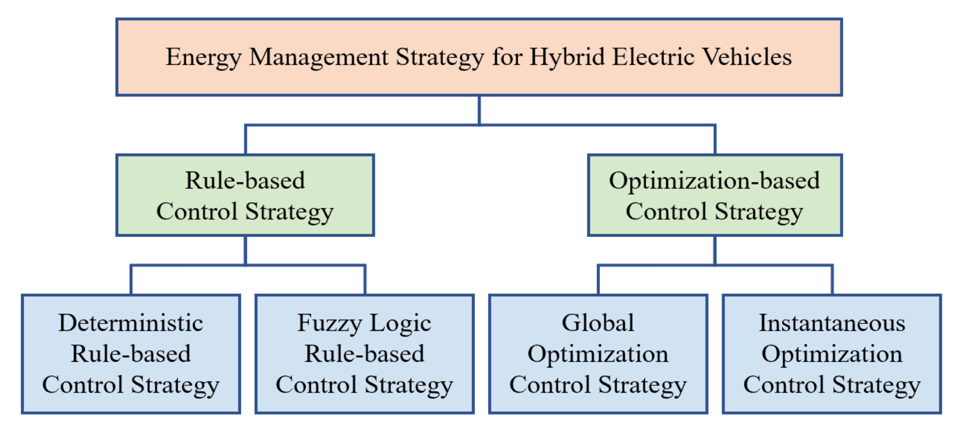
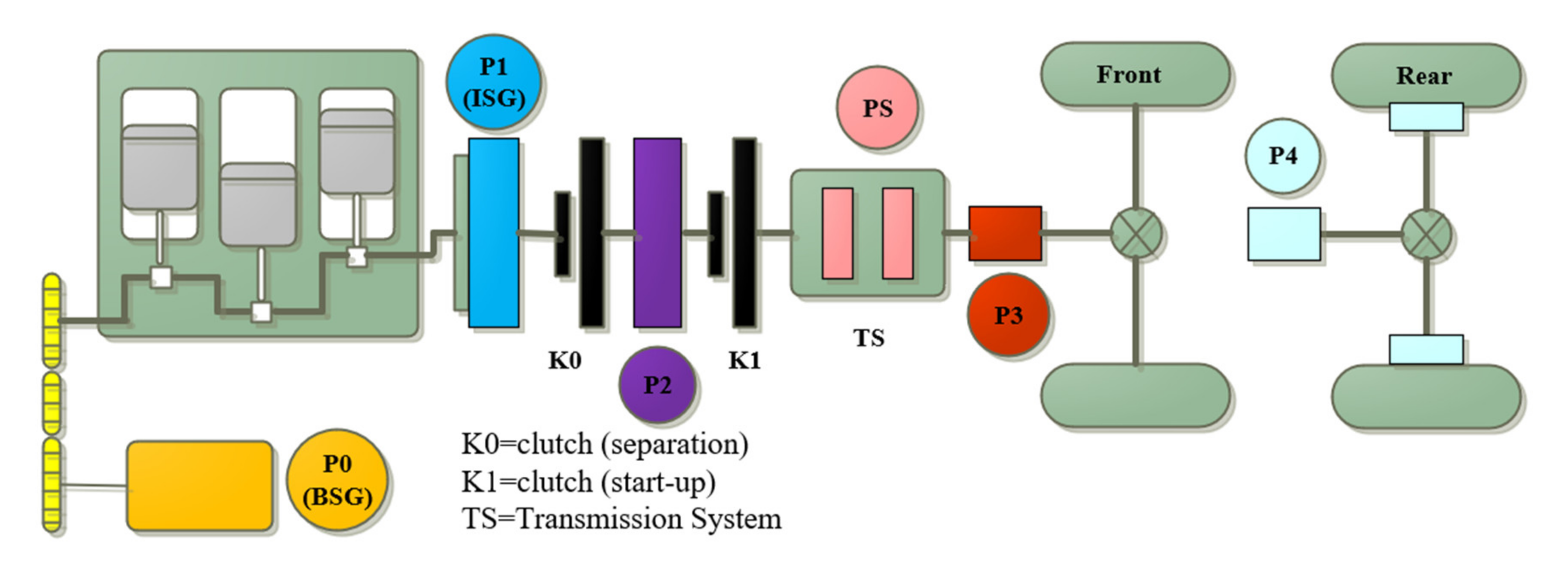
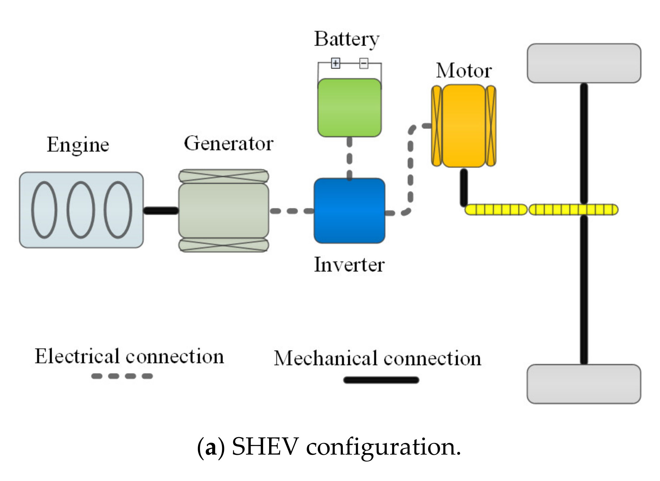
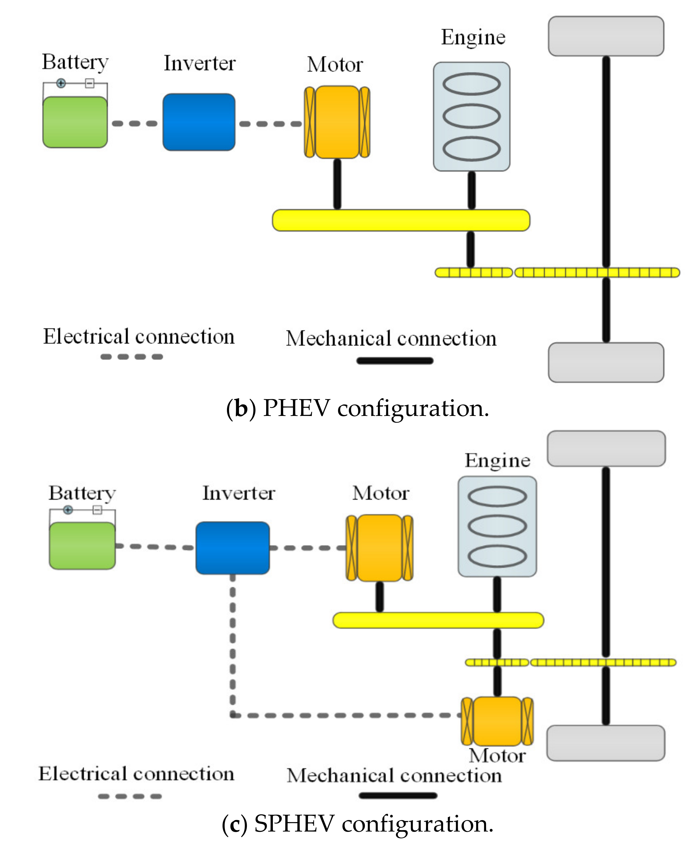
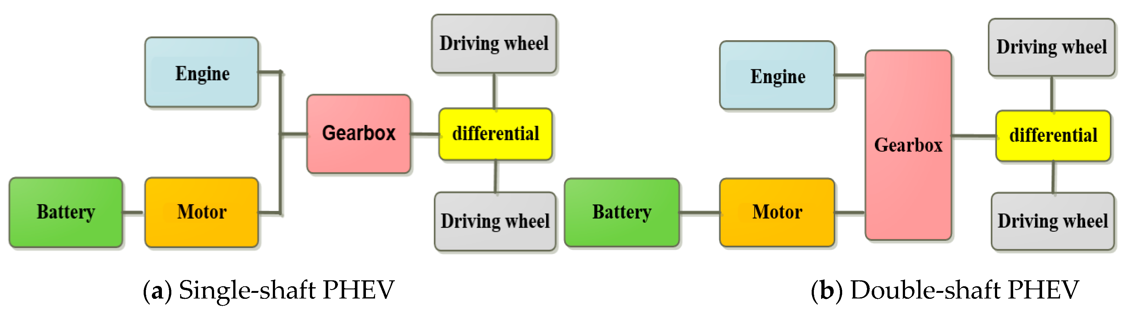
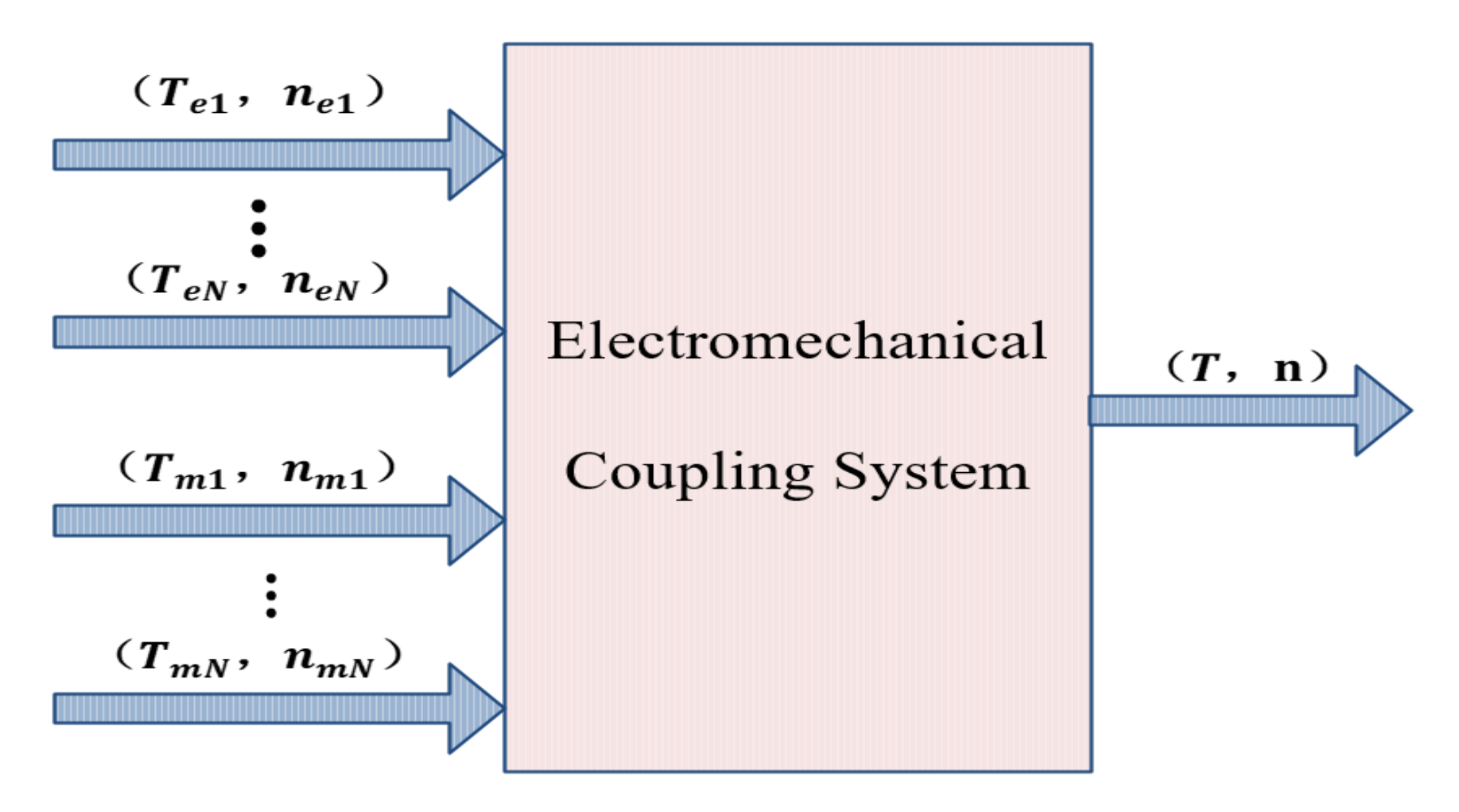
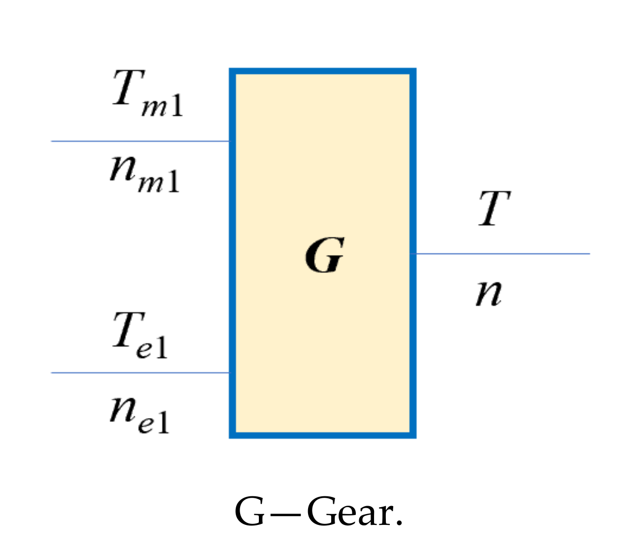
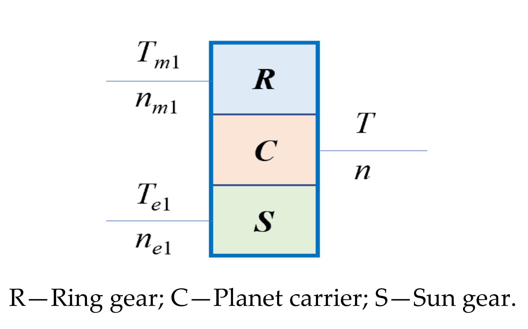
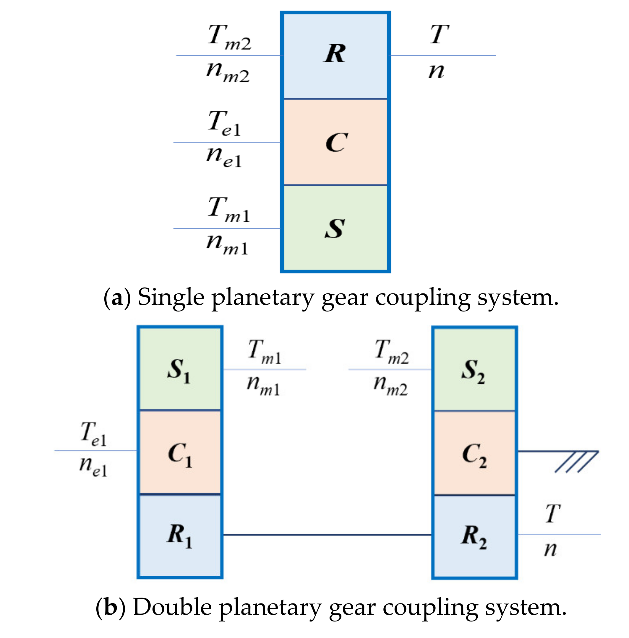
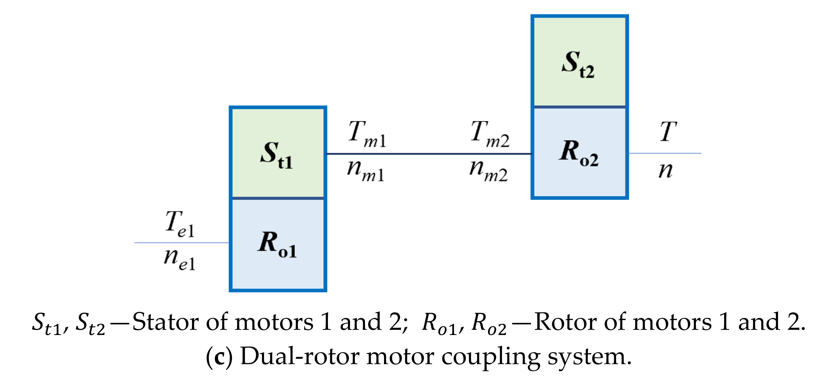
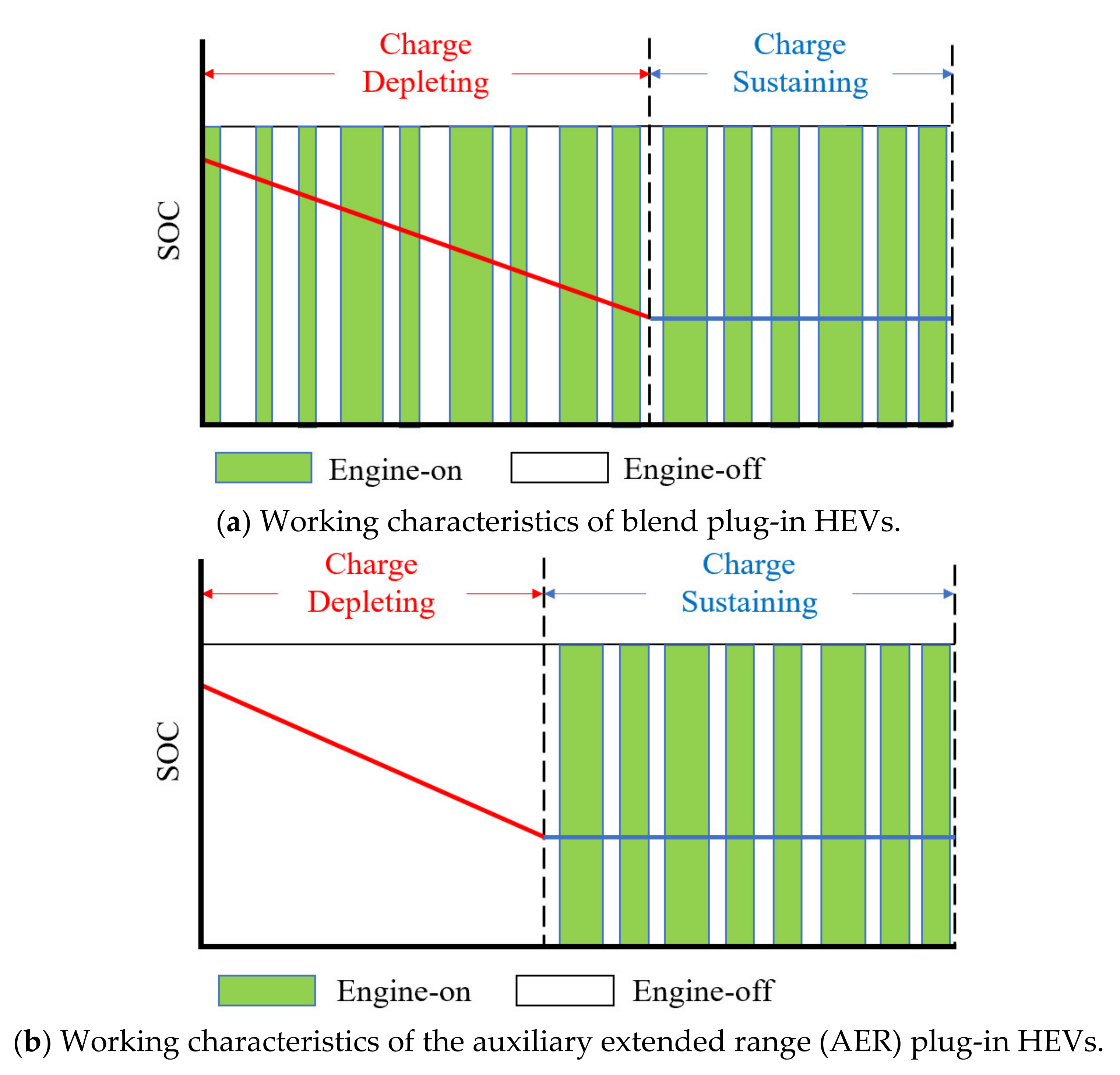
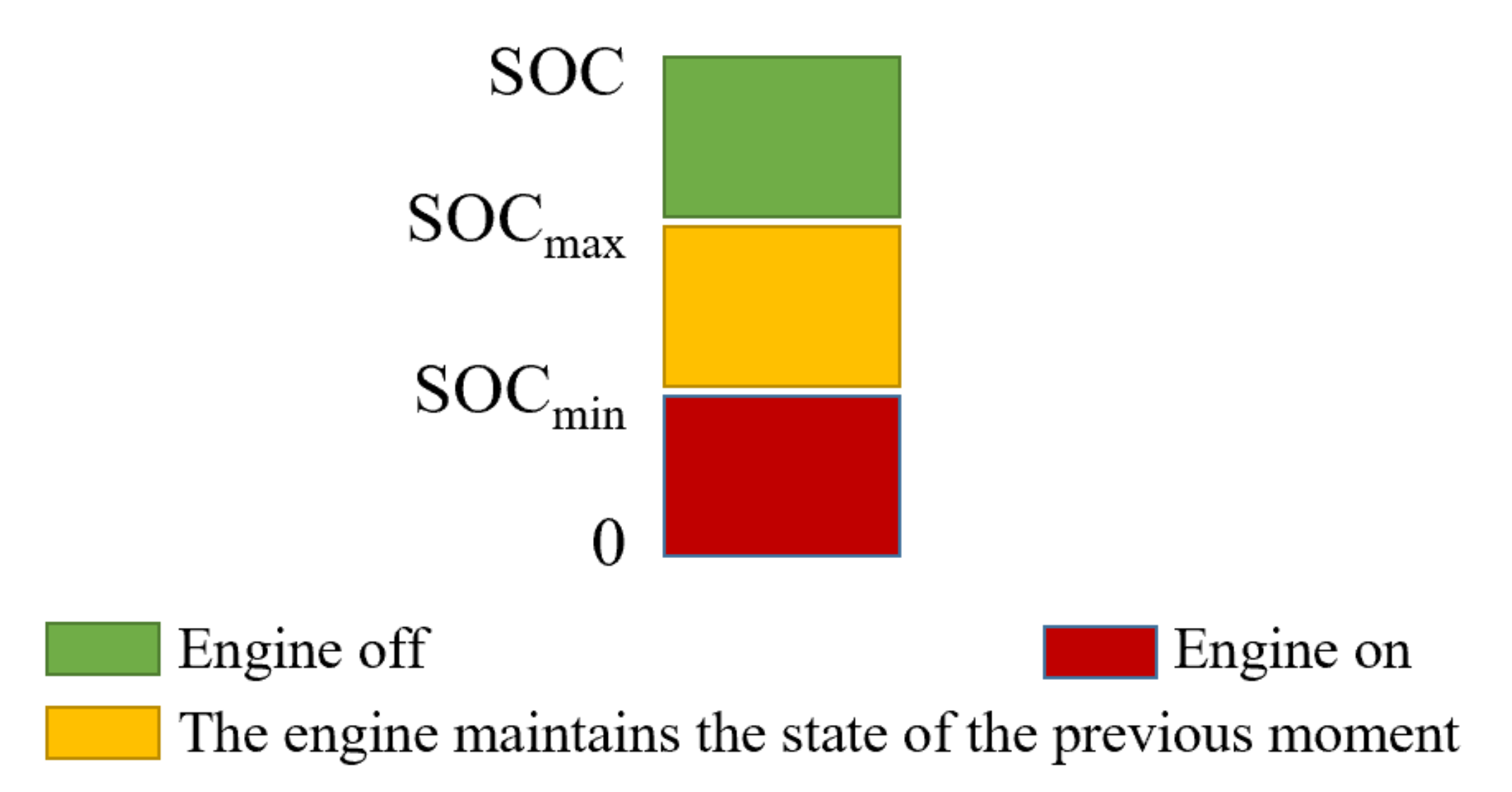
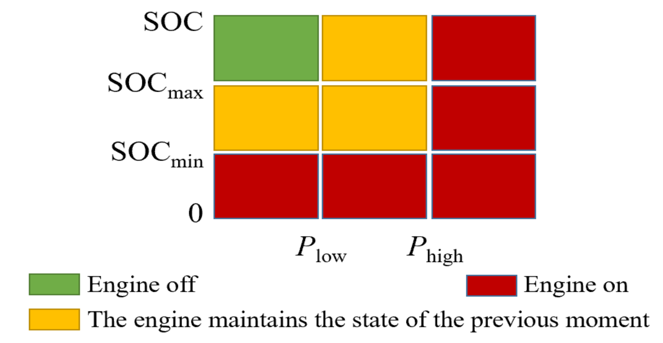
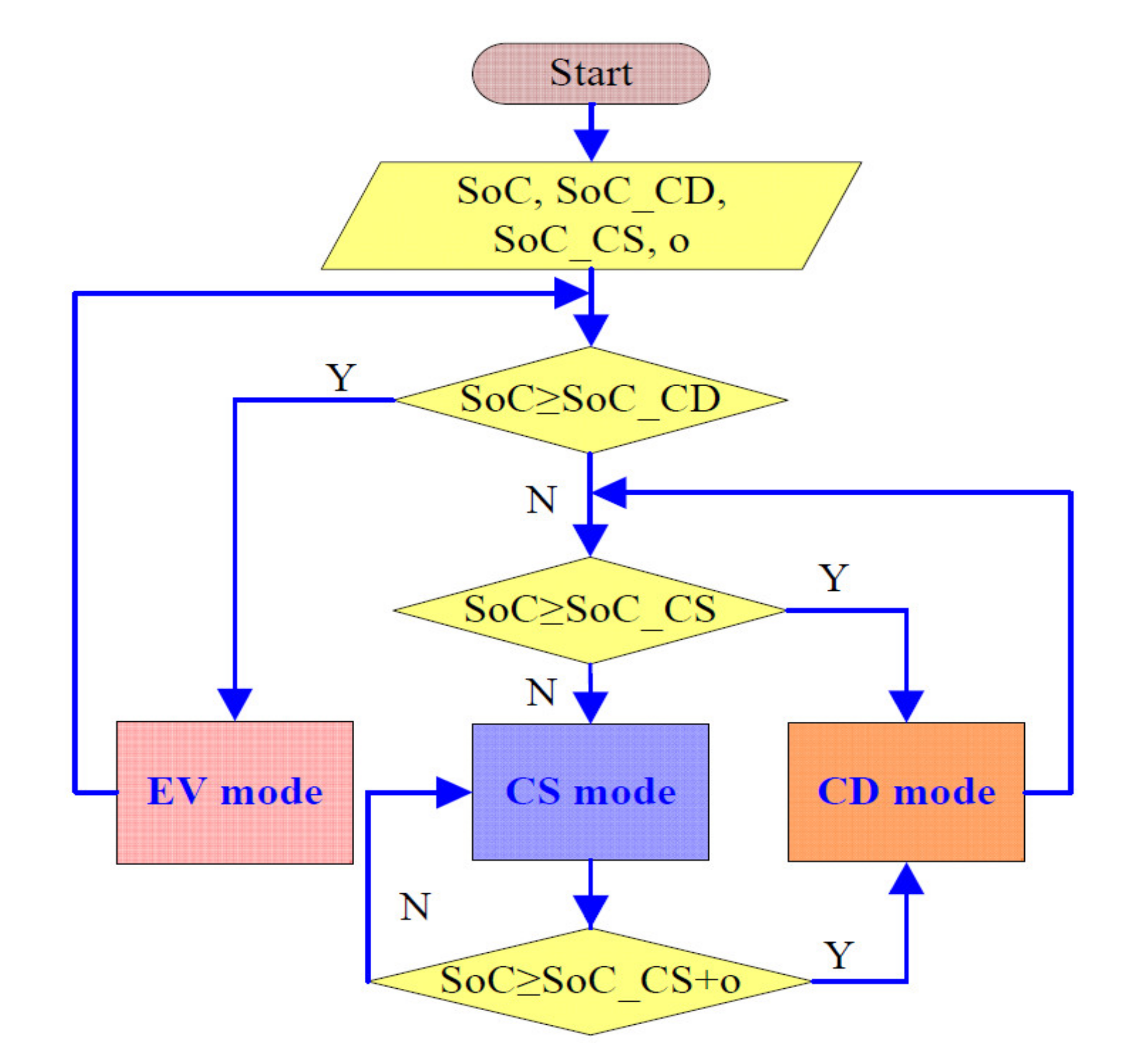
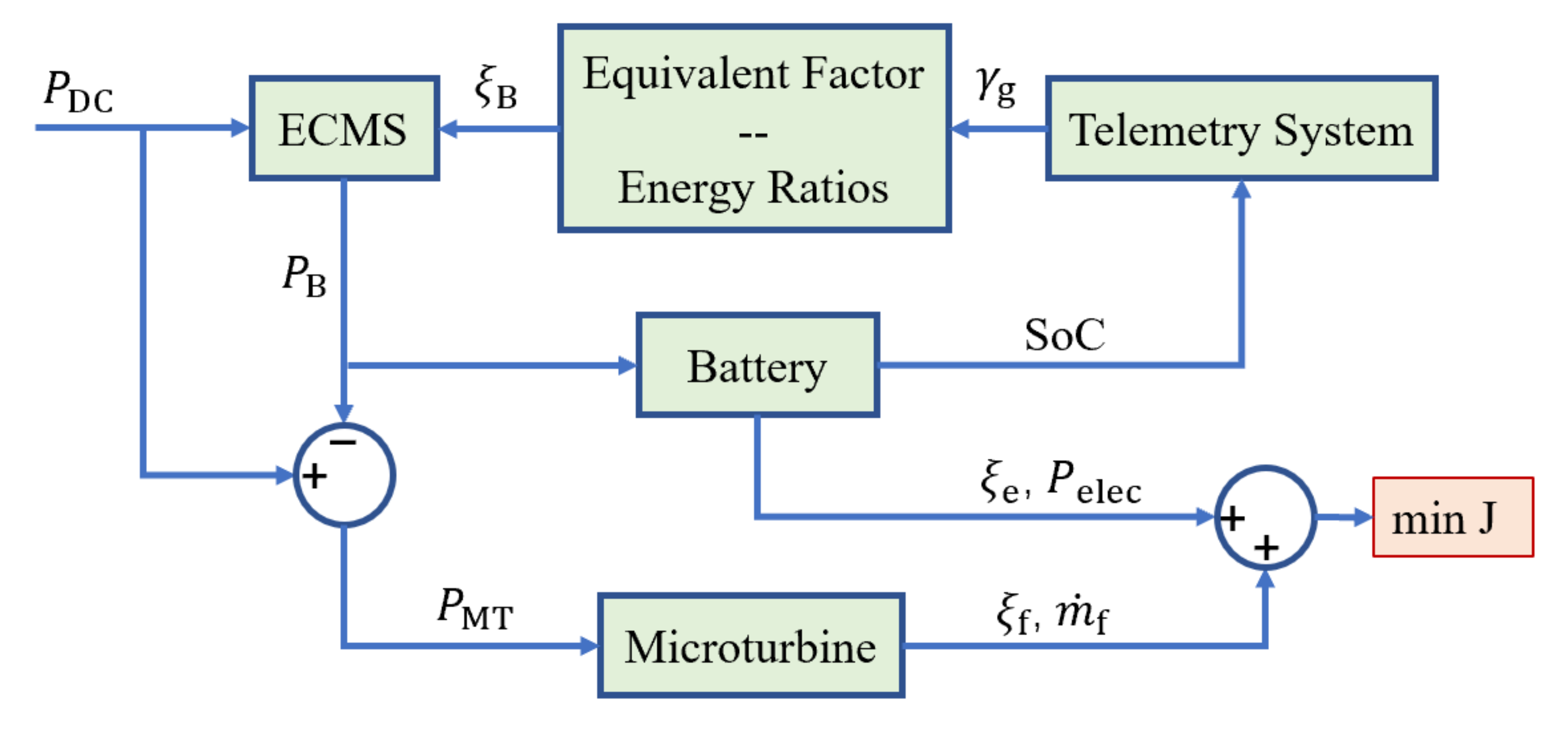
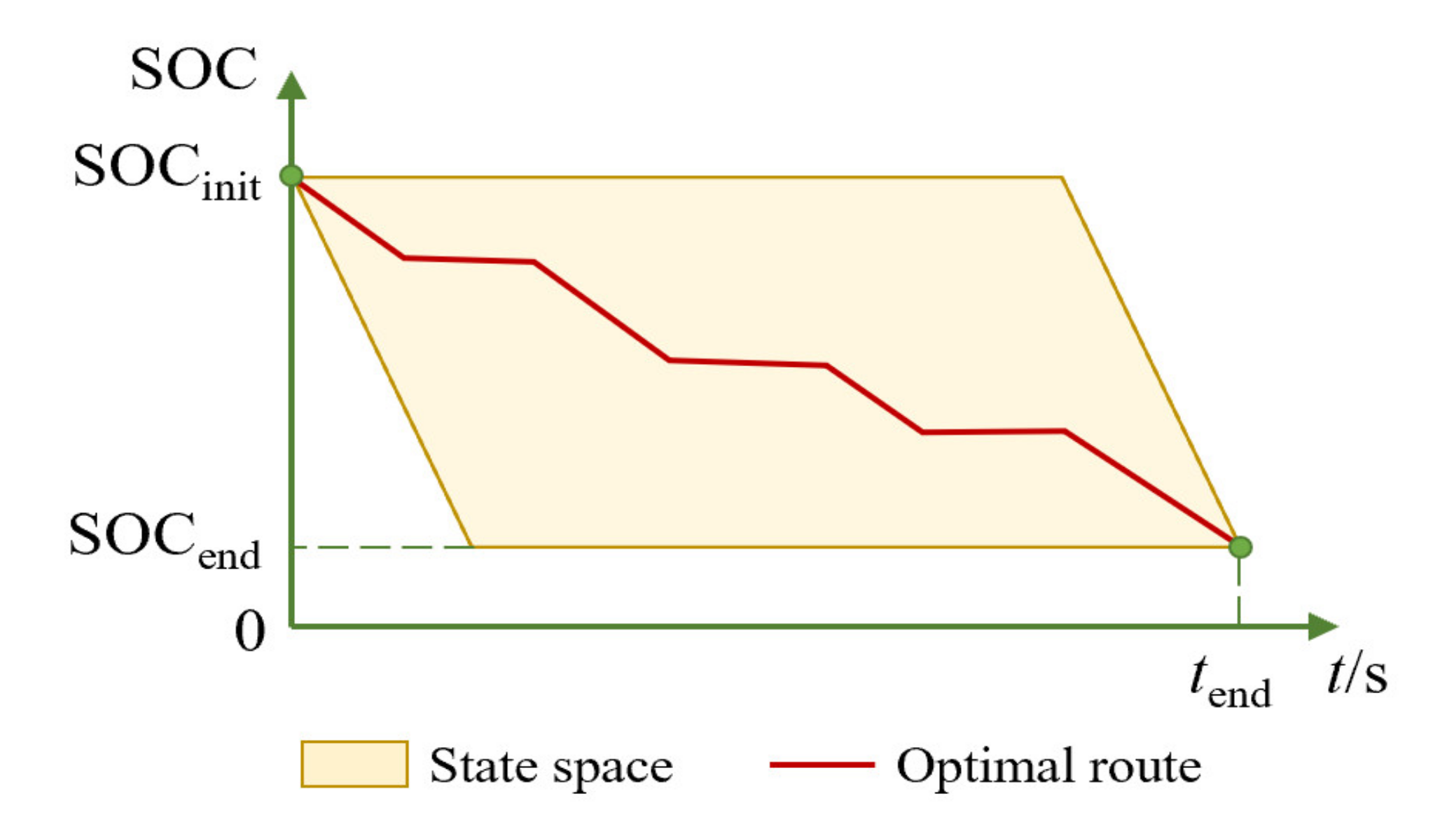
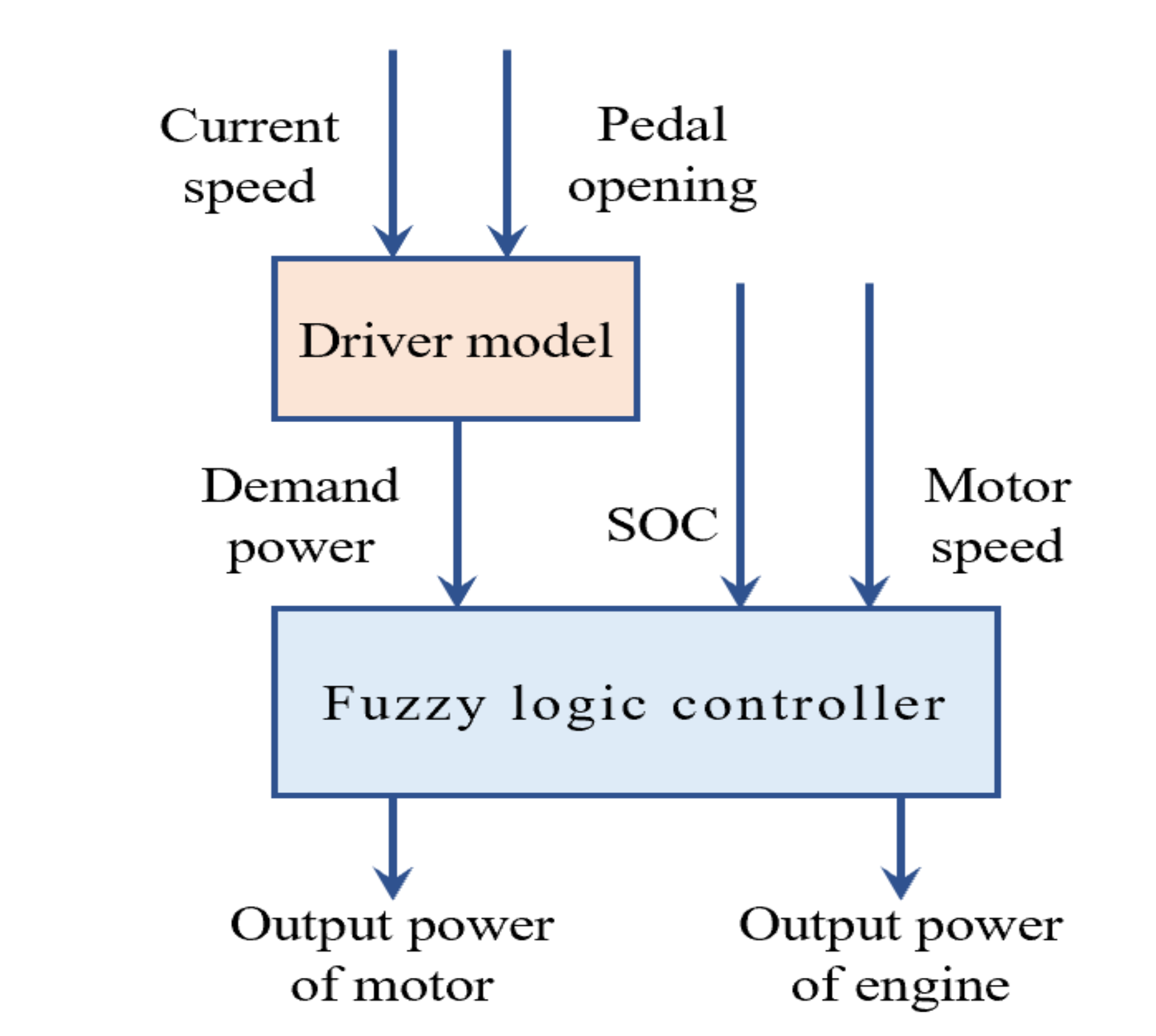
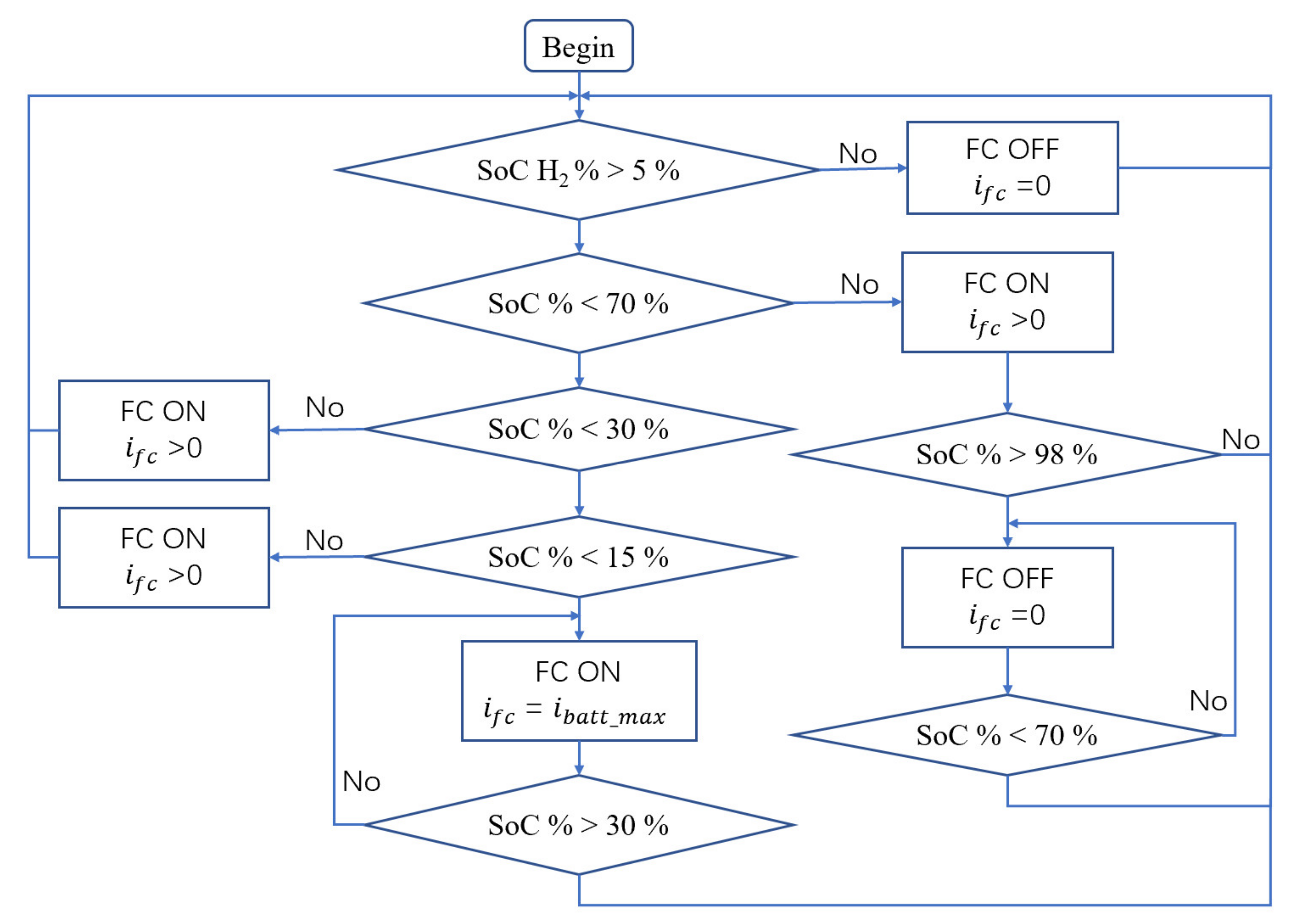
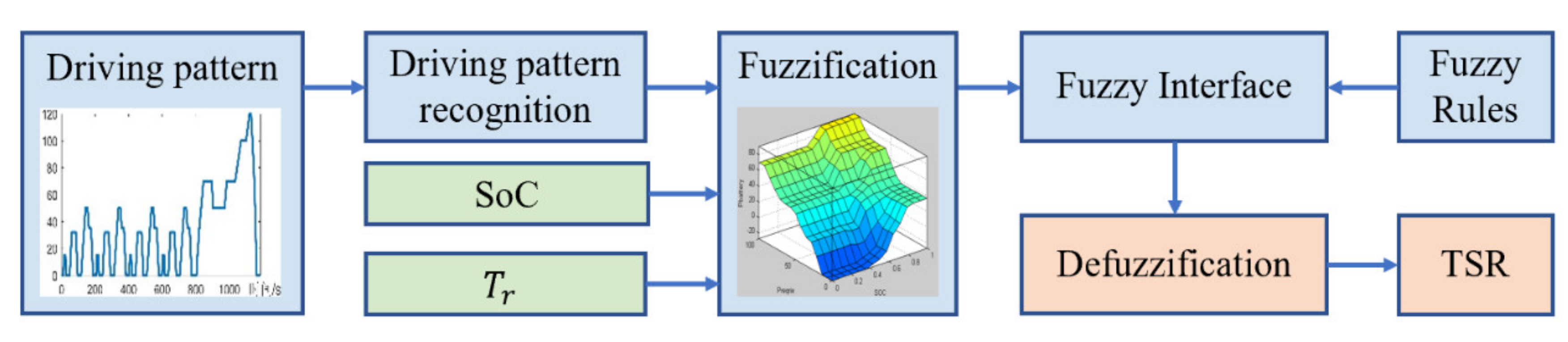
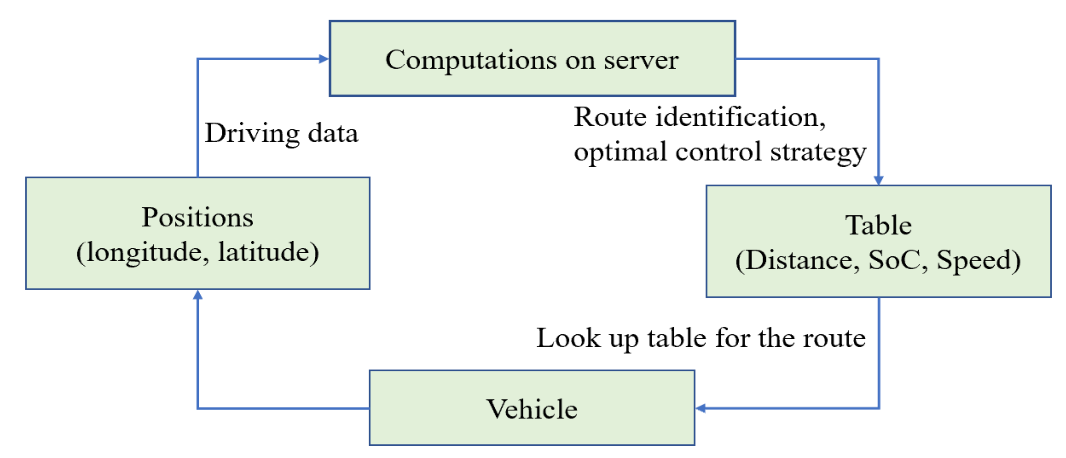
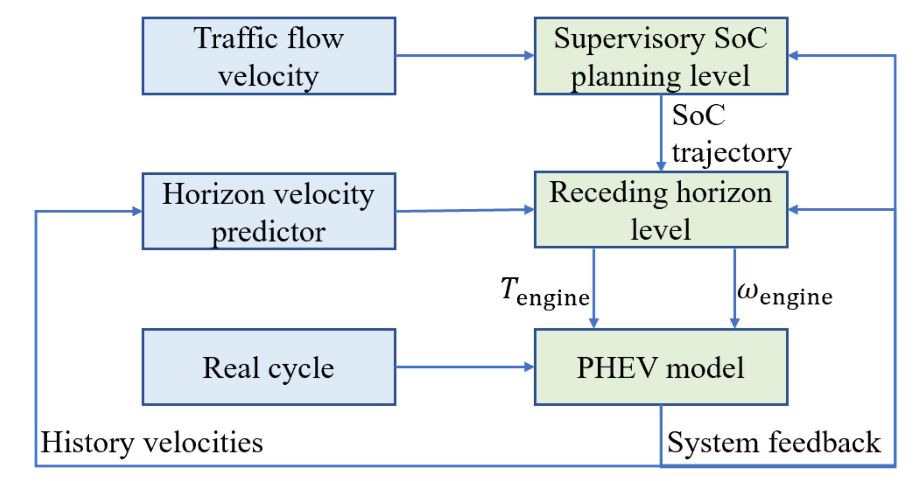
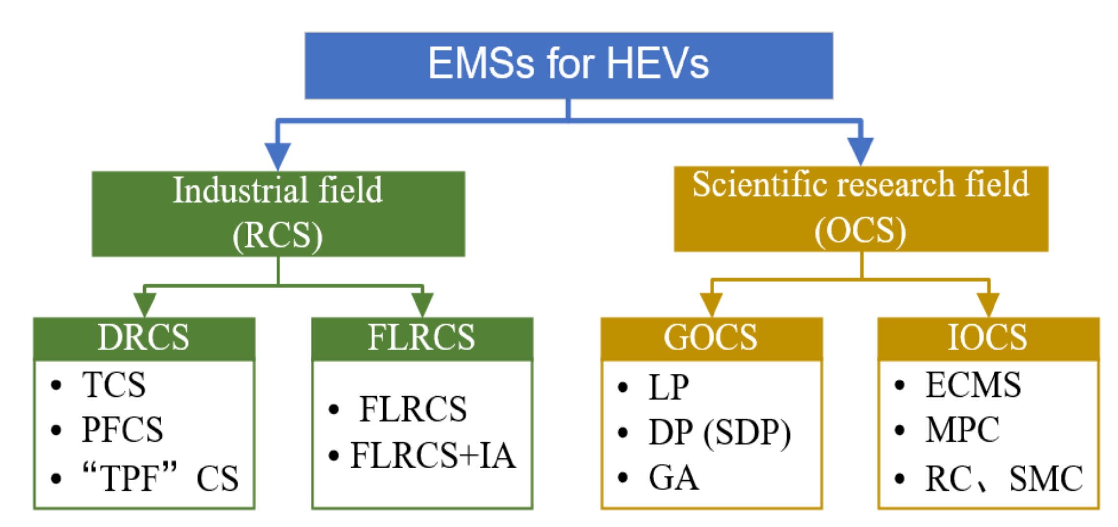
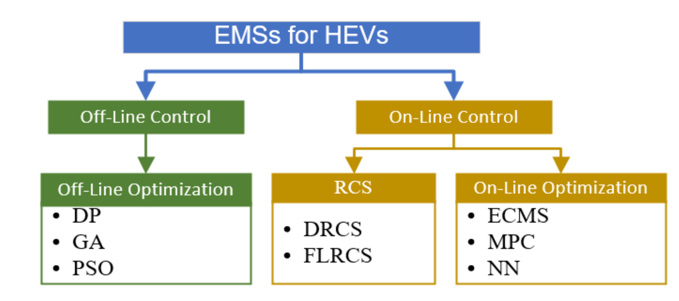
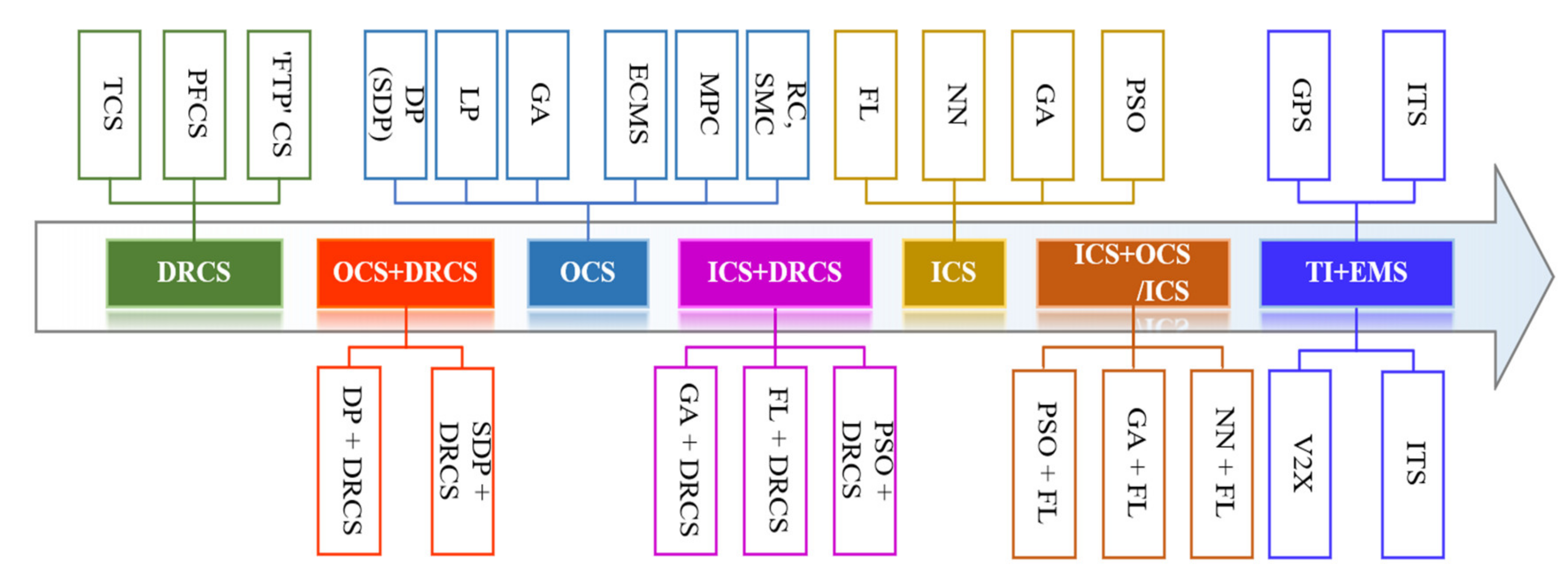