1. Introduction
Solar energy is considered to be one of the promising renewable technologies in now-a-days efforts for developing energy research [
1]. The versatile commercial renewable energy systems could be potentially utilized as main electricity sources for catalytic energy conversion [
2,
3]. Splitting water into hydrogen and oxygen is proven to be a feasible, reliable, sustainable, and environmentally friendly process [
4]. Hydrogen is a promising high energy content fuel compared to fossil fuel and better suits the environment with respect to toxicity and a reduction in the effect of greenhouse gases (GHG) [
5]. Therefore, vigorous research aims at developing and optimizing fuel hydrogen production and maximizing the product yield from the water-splitting rates [
6]. The enormous energy requirements for hydrogen production throughout water splitting (water electrolysis) is the major drawback of this technique. However, integrating water electrolysis into wastewater-treatment, the cost of hydrogen production is reduced and compromised for practical applications [
7,
8,
9]. It is well-known that the cost of electrochemical processing is driven by the consumption of electric energy. Therefore, exploring innovative electrode materials is a novel approach for improving the process’s competitiveness [
10].
Recently, copper oxide (CuO) and zinc oxide (ZnO) nanoparticles (NPs) have exhibited stability under the catalytic reaction and showed interesting properties in catalytic water-splitting for hydrogen production applications [
11,
12].
Boron-doped diamond (BDD) electrodes are usually deposited on conductive substrates to be used for electrochemical oxidation [
13]. The BDD has unique electrochemical properties and extreme chemical resistance for oxygen and hydrogen evolution reactions operated at extremely high voltages [
14]. Additionally, the double electrochemical processes for wastewater treatment (oxidation reaction at the BDD anode) and hydrogen progression through reaction reduction can simultaneously take place at the BDD cathode, revealing a significant improvement in energy efficiency [
15,
16].
Minimizing the kinetic overpotentials to reduce the cost and to improve the system efficiency is an important goal in efficient water-splitting catalysis [
17,
18,
19]. Adding non-noble elements, such as Ta, Ti, Sb, Nb, and Sn, as dispersing or stabilizing agents is one of the challenging approaches to minimize the kinetic overpotential [
20]. During long-term operation, non-noble elements can be easily oxidized leading to rapid degradation. Metal-oxides have good corrosion resistance and exhibit strong catalyst properties [
21].
In this work, a catalytic and energetic water electrolysis (splitting) by employing BDD electrodes was performed by using CuO NPs and ZnO NPs. A noncatalytic (pH-controlled water-puffer) reaction was performed for comparison purposes. The electrochemical parameters, such as electrical current (I), acidity (pH), electrical conductivity (σ), input, and dissipated energies, as well as the efficiency of the electrochemical process were investigated and reported. The data for the input and the dissipated energies were used for calculating the fraction of the energy used for the water-splitting and the overall efficiency of the process.
2. Materials and Methods
The electrochemical water electrolysis splitting experiments were conducted at starting solution temperature of 24.3 °C in 2 L Plexiglas laboratory-scale reactor. Buffer solution was prepared from 380 mL of distilled water. This distilled water was mixed with 10 mL of tap water supplied from the laboratory faucet. The calibration of the pH levels was made by gradual addition of 100 µL of the standard buffer solutions (Scharlab standard Buffer Solution pH 4 potassium hydrogen phthalate) and pH 7 (3.54 g/L of potassium dihydrogen phosphate, 14.7 g Disodium hydrogen phosphate)) until pH = 6.5 was reached. Then, measurement of the electrical conductivity was performed using a conductivity meter while ensuring the initial conductivity to be between 140 µS/cm and 160 µS/cm.
The electrolysis-setup comprises two mesh BDD/Nb electrodes serving as an anode and as a cathode, with a geometrical surface area of 63 cm2, and spacing between the two mesh electrodes of 1 mm. A temperature sensor coated with ceramic was placed inside the solution.
The BDD/Nb electrodes were prepared with hot filament chemical vapor deposition (HFCVD) coating technique while using two parallel filament rows in the process. The coated BDD film was found to be of 8 μm thickness. Niobium mesh substrate (mesh type C1_METAKEM GmbH) was mechanically pre-treated with particle blasting method to enhance its surface roughness for enhancing the adhesion of diamond. The treated Niobium (Nb) mesh substrate was ultrasonically cleaned with ethanol for two minutes and seeded on the surface by using nano diamond dispersion in ethanol. Seeding process was performed by employing diamond nucleation using ultrasonic process based on the protocol used in reference [
22]. Coating the BDD was carried out in HFCVD equipment at low pressure (7 mbar) in CH
4/H
2 atmosphere and activated via a resistively heated tungsten filament. Trimethyl borate (B(OCH
3)
3) (supplied by Sigma Aldrich Co. Inco.) was incorporation in the gaseous mixture to provide boron doping agent for the diamond film in order to improve its electrical conductivity and produce conductive diamond electrodes.
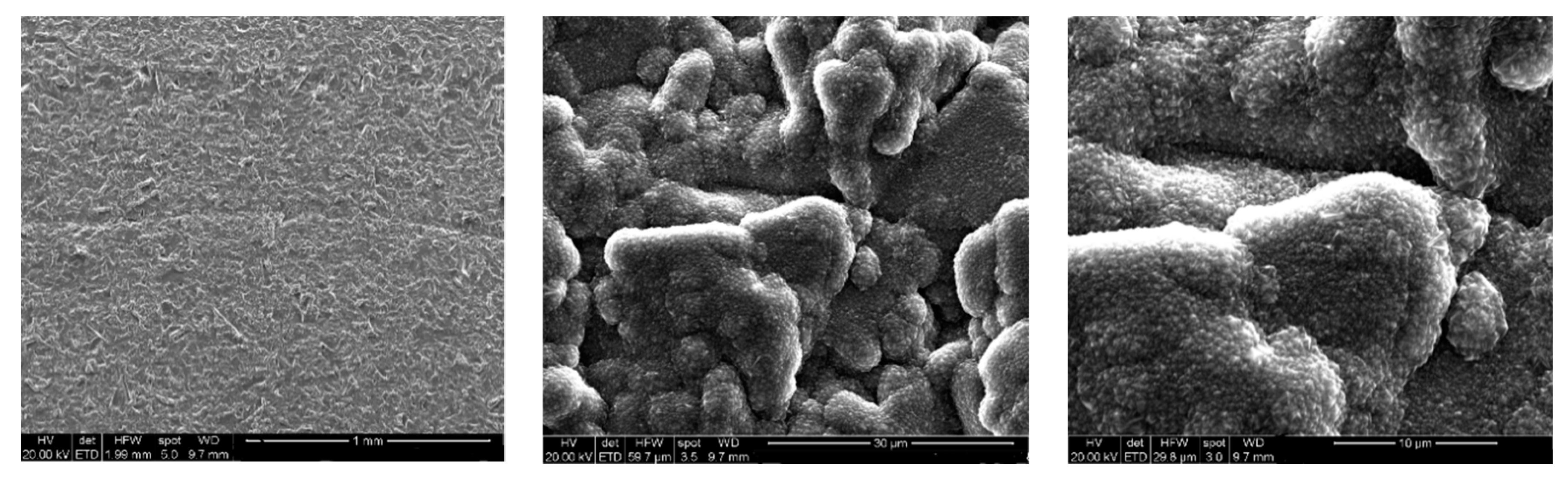
The SEM images (different magnifications) of the deposited BDD thin layer on the niobium mesh substrate (
Figure 1) show a surface-roughness in several micrometers due to the raw niobium substrate surfaces roughness in addition to the roughness of the deposited BDD layer (typically, the diamond thickness is around 6–8 μm). The high quality of coating (high-efficiency factor) leads to full coverage of the mesh substrate, allowing the entire area of the electrodes to contribute to the electrochemical oxidation and the water splitting processes [
23,
24,
25,
26,
27].
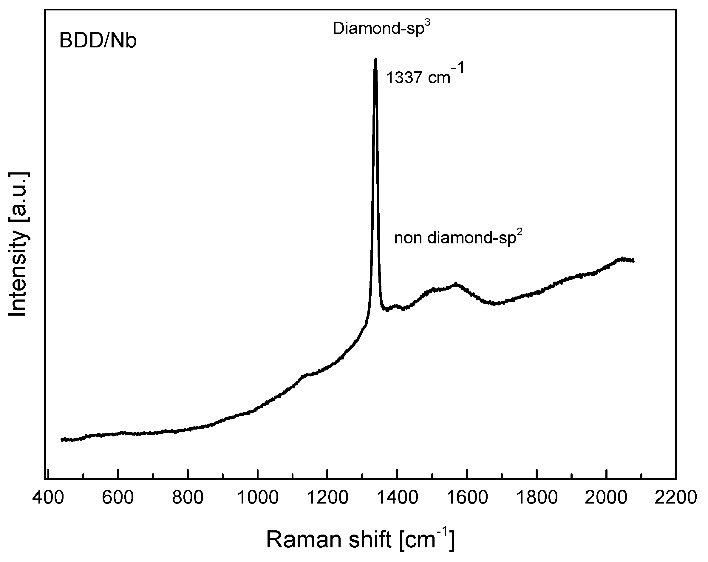
The quality of the boron-doped diamond film was clarified clearly by using Raman spectroscopy. The pure diamond (sp
3) and the other non-diamond (graphite with sp
2) phases are checked by micro-Raman scattering spectroscopy (Renishaw Ramascope 2000) technique by using an argon-ion laser
with wavelength of 514.5 nm. The spectrum obtained from Raman spectroscopy seen in
Figure 2 exhibits high film quality BDD. The crystalline BDD peak is observed to be at wavelength of 1337 cm
−1 relative to the native diamond line at 1332 cm
−1 [
28]. This positive peak-shift is believed to be related to the compressive residual stress that occurred in the deposited BDD film. Moreover, the broad band observed between 1507 and 1569 cm
−1 is related to the graphite phases in the diamond structure.
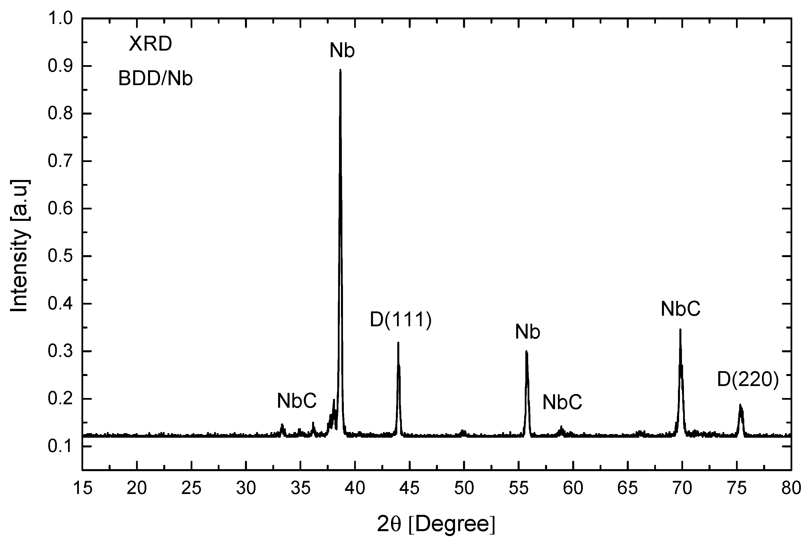
The phase composition and crystal structure of BDD/Nb electrodes were characterized by an XRD Philips PW1700 X-ray diffractometer with Cu target (λ = 1.54185 Å) operating at 40 kV/40 mA. The typical XRD diffraction peaks of BDD/Nb electrode (
Figure 3) are observed at 2θ = 43.9° and 75.2°, which are assigned to the (111) and (220) facets of the diamond composition. The intensity of BDD peak for the plane (111) is much higher than that for the BDD (220) indicating that the BDD films have preferred orientation in the direction of (111) facet. The sharp peak for the BDD structure at 2θ = 43.9° indicates that it exhibits a well for of crystallinity. Niobium carbide peaks were also observed in the patterns and are believed to occur due to the carbonization of niobium substrate during the BDD deposition process via the HFCVD technique.
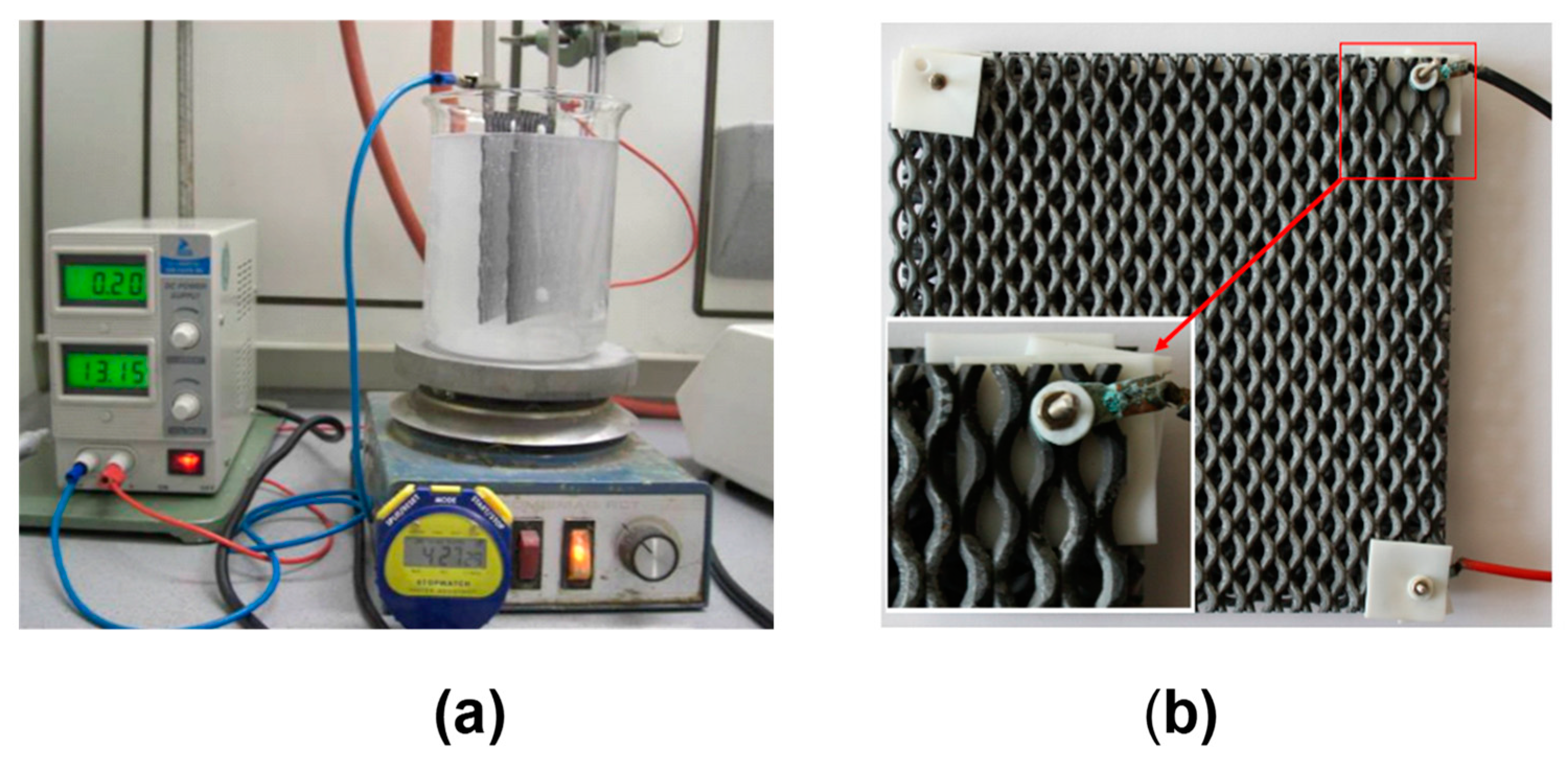
The BDD/Nb electrodes were connected to a DC power supply (Gwisntek GPC 30300) with 3 A and 30 V outputs of current and applied voltage, respectively. Distilled water, CuO NPs, and ZnO NPs (supplied by Sigma Aldrich Co. Inco.) were used in this catalytic electrochemical process, as seen in
Figure 4a,b.
The voltage (V), current (A), conductivity (µS/cm), acidity (pH), sample temperature (°C), ambient temperature (°C), and accumulative time (Min.) were the primary parameters monitored during the experiment. The voltage and electrical current have been simultaneously recorded at each time interval. The temperature inside the reactor and the ambient temperature were recorded consecutively by using two separate thermometers.
3. Results
3.1. Current (I) and Thermal Characteristics
The Joule heating due to the current flow has been investigated during the electrochemical water-splitting process. The energy (in Joules) supplied to the system at constant current (
I) for a period of time (
t) at an applied potential difference (
V) is given by:
This energy is converted into a work producing a driving force for random motion as thermal activation for the molecules and the charge carriers.
The dissipated rate of work (power,
P) consumed in the process in the form of heat transfer is:
For convenience, the high power dissipated per long time is given by the units of kilowatt-hour (kWh).
3.2. Current (I) and Period of Time (t) Characterization
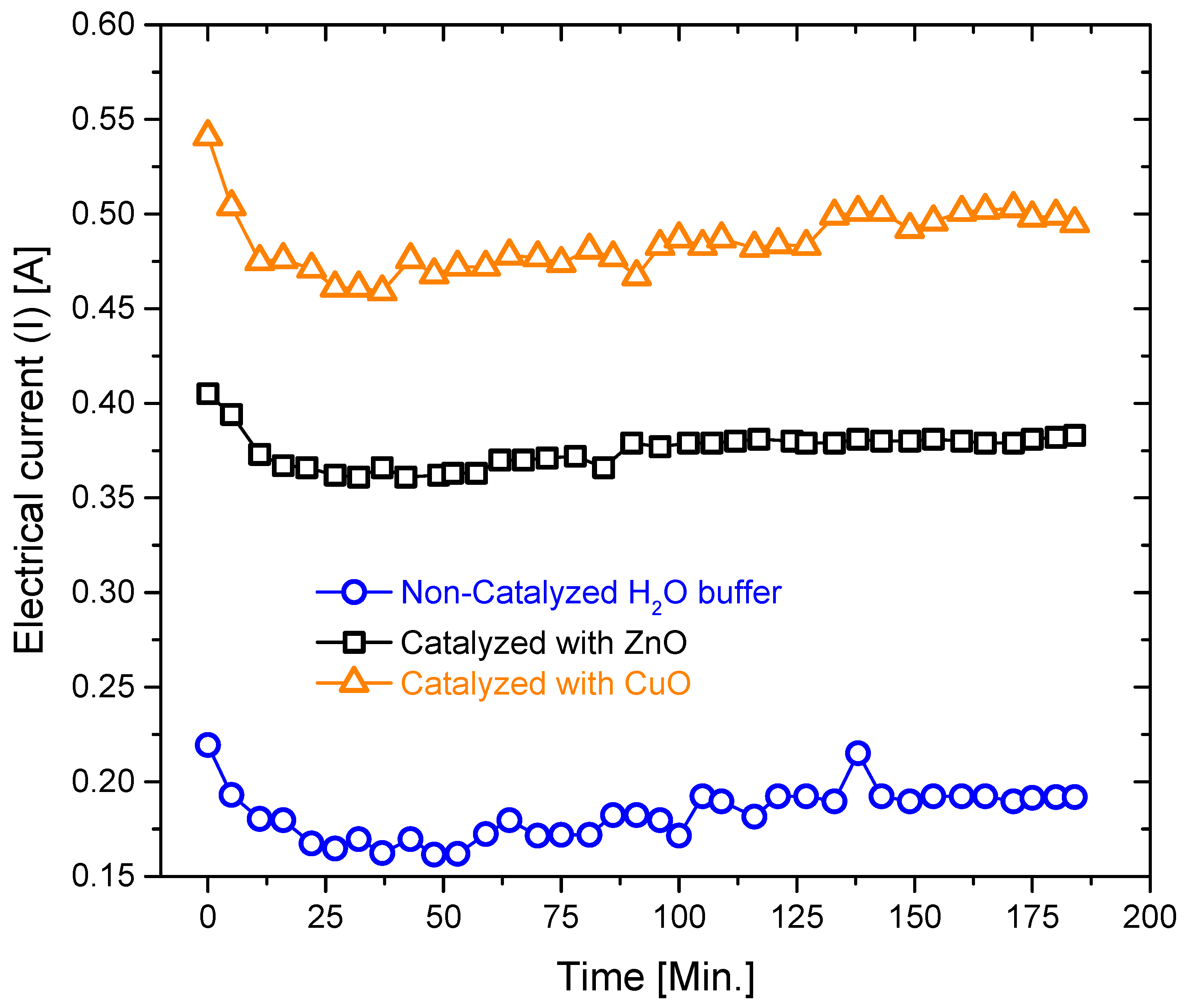
It has been found that the electrical current in the non-catalyzed system (buffer solution pH-6.5) increases with the period of time on the contrary to that used for the systems catalyzed with CuO NPs and ZnO NPs as seen in
Figure 5. The increasing value of the electrical current in water could be attributed to the relevant increase in the effective conductivity, which is a result of the change in the acidity due to the electrochemical reaction. The periodical patterns of the electrical current seen in the curve are associated with the solution polarization. This polarization phenomenon is very weak in the catalyzed systems because of easy charge transfer (ionic solution). Catalyzed systems (Buffer solution with dissolved CuO NPs and ZnO NPs) show similar trend, and both curves dropped down to a stable value after the first 1000 s. This behavior follows the conductivity behavior, and indicates that the electrical conductivity mechanism is driven by the ionic charge transportation [
29,
30]. The slight smooth increase in the current after the first significant drop is attributed to the change in the acidity of the system, which is similar to the non-catalyzed system and/or the effect of temperature elevation (
Figure 3).
3.3. Voltage (V)—Period of Time (t) Characterization
A DC voltage source used as a power supply was used the course of the experiment in order to keep the applied voltage constant and stable over the whole time. Typically, voltage source is a two-terminal device which can maintain an invariant voltage [
31]. Thus, an ideal voltage source can preserve the invariant voltage, irrespective of the load resistance and/or the yield current.
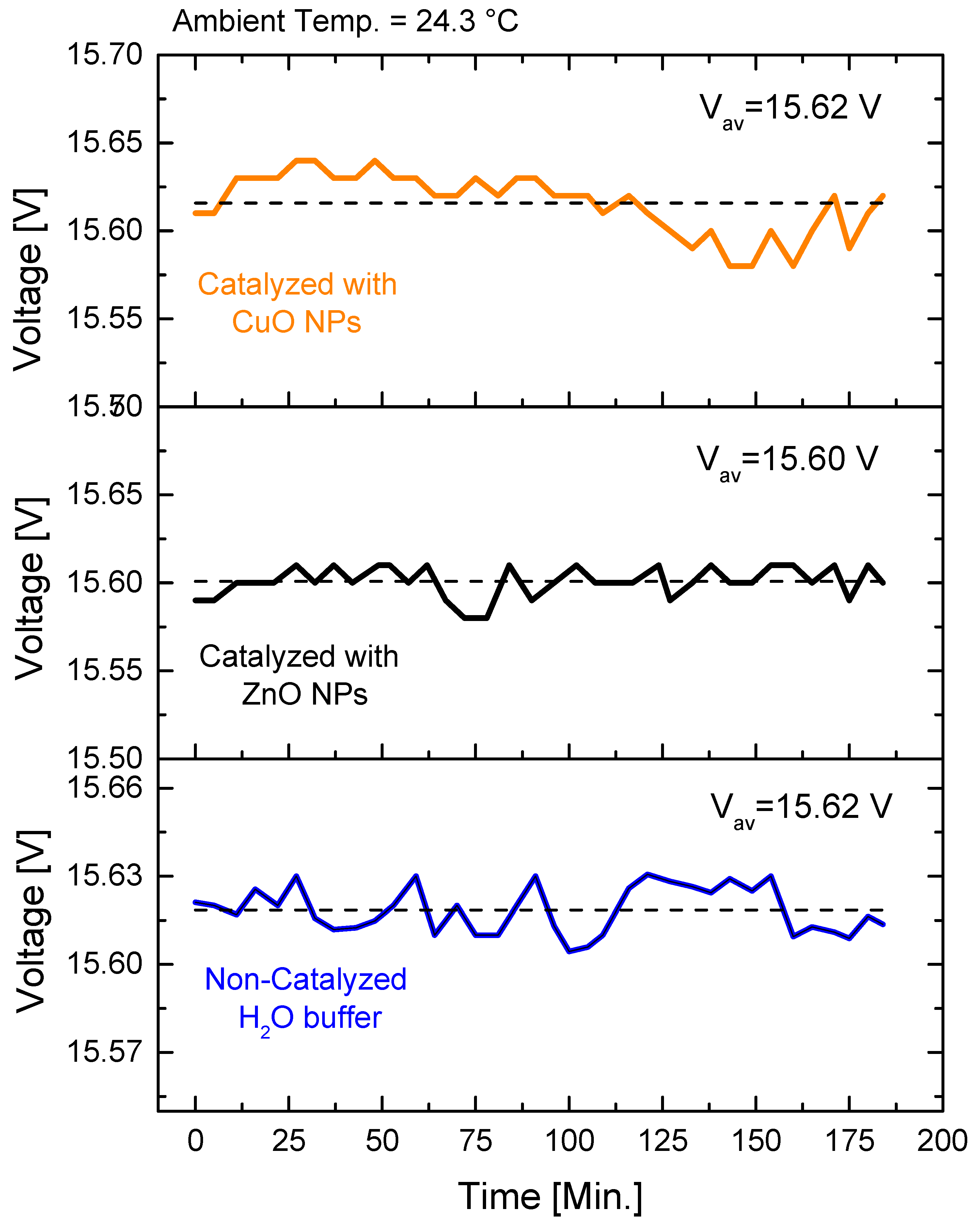
Figure 6 shows the applied voltages for the three systems. The voltage is stable and constant within the experimental error margin.
The voltage shows an insignificant decrease with time progression in the non-catalyzed system (water at pH 6.5), which probably might be due to the ionic polarization in the solution [
32]. On the other hand, the voltage in the catalyzed systems with CuO NPs and ZnO NPs is almost constant. This might be attributed to the attenuation of the solution polarization because the CuO NPs and the ZnO NPs lead to facilitate charge transportation through the surface charges and the nanoparticle percolations.
3.4. Temperature (T)—Period of Time (t) Characterization
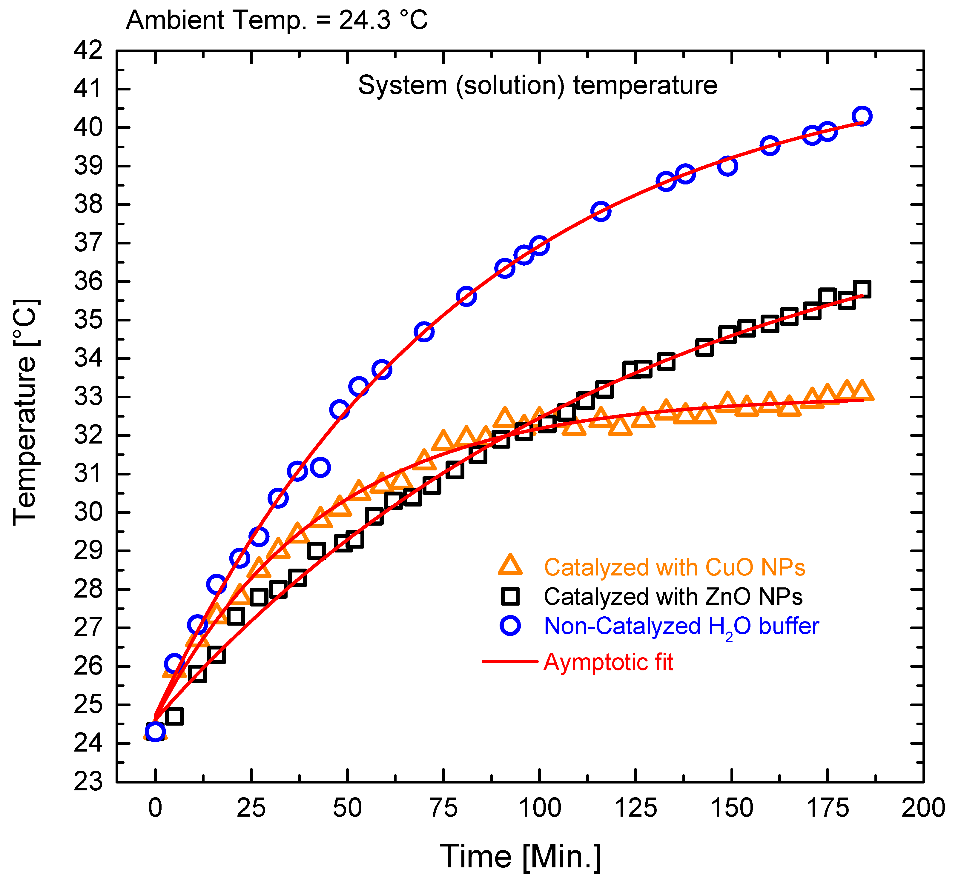
Both catalyzed, and non-catalyzed systems show an increase in energy (Joules (J)) heating with time (
Figure 7). Even though the voltage was almost constant during the measurements and the variations were insignificant, still, the temperatures were accumulatively increasing with time. This is a direct result of the increasing current and the heat accumulation effect (the generated heat is more than the heat dissipated into the surroundings), however, after long enough time, the heat reaches an asymptotic approach. This asymptotic approach is due to the superposition of Joule heating (which adds energy to the system) and the heat losses to the ambient in addition to the latent heat of vaporization (the energy absorbed by evaporating 1 g of water is 2259.4 J) from the surface.
The temperature evolution trends in the catalyzed systems are similar to each other, and they follow asymptotic behavior indicating that the energy is being used for both heating and water splitting. The temperature of the system catalyzed with CuO NPs was the minimum in the asymptotic approach, in which the balance between the input energy and the output energy show that the energy of splitting is the highest since the other two systems did not reach the asymptotic situation. The balance situation is attained at higher temperature.
3.5. The Acidity (pH) and the Period of Time (t) Characterization
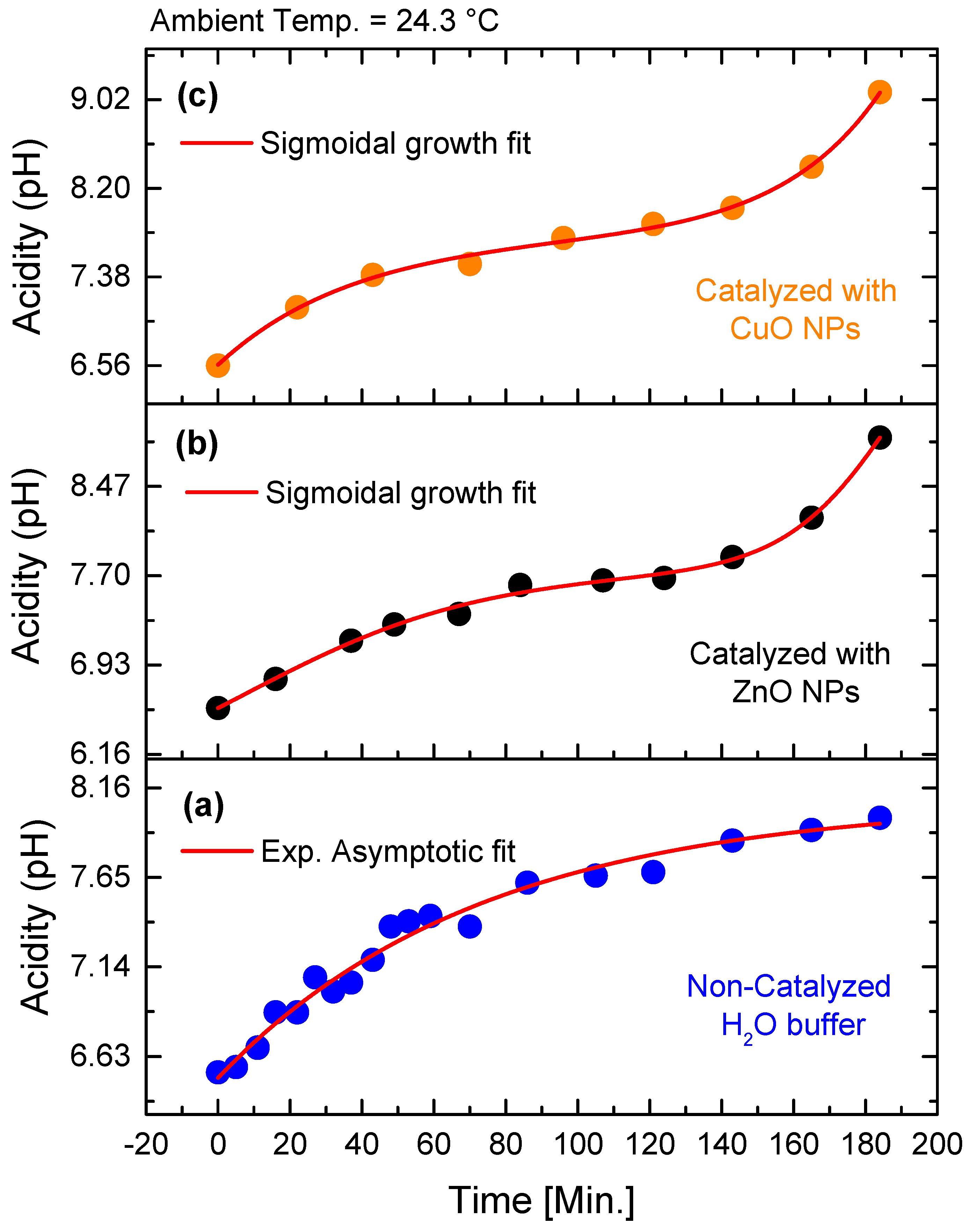
The acidity (pH) of the non-catalyzed system (water buffer with pH 6.5) follows the exponential asymptotic behavior (
Figure 8). The pH level of the systems catalyzed with CuO NPs and ZnO NPs follow sigmoidal growth behavior and can perfectly fitted to this function. This behavior is similar to the typical titration curve [
33]. The rate behavior of the acetic acid ionic dissociation reaction obeys the sigmoid S-shaped curve. The dissociation constants of the acetic acid for any initial water content are expressed perfectly with the Sigmoidal fitting function. The Sigmoid kinetics typically represents the co-operative interaction [
34]. This behavior indicates the dynamics of the ionic and the ionic clustering, such as generating different copper oxides (Cu
2O or nanoparticle heterogeneity).
The pH behavior in the system catalyzed with ZnO NPs illustrates that the ionic generating new products is almost flat from 40 min up till 140 min. Interestingly, the acidity of all the systems shifts towards the basicity states by progressing the electrochemical reaction.
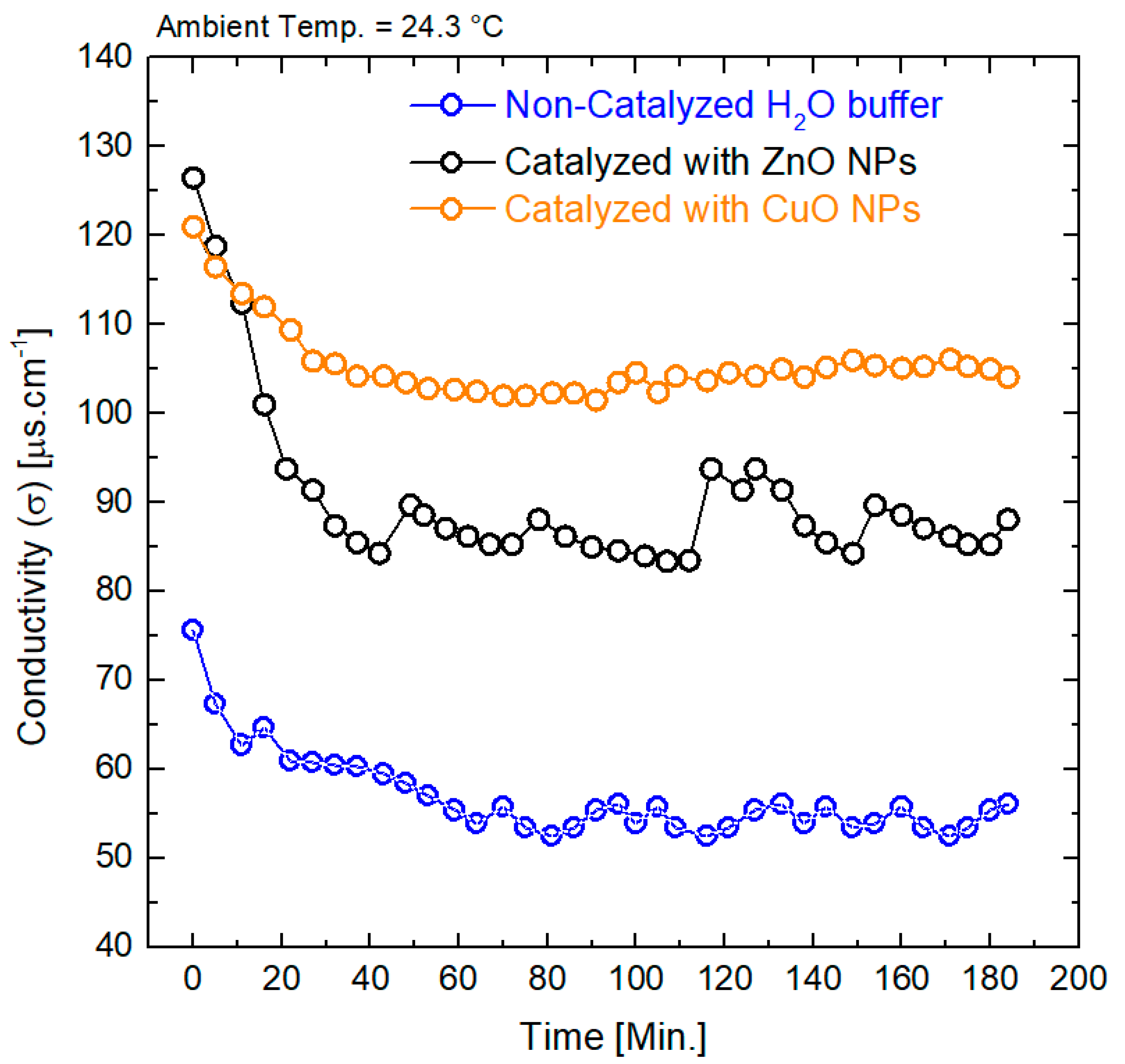
3.6. Electrical Conductivity (σ (S/cm)) and the Period of Time (t) Characterization
The electrical conductivity in the catalyzed and the non-catalyzed systems show periodic patterns that might be related to the ionic clustering formation in addition to the Brownian motion while counteracting each other (
Figure 9). The electrical conductivity (
σ) of all the systems grew towards the asymptotic values of the exponent. The non-catalyzed system reached the asymptotic value at around 60 min while the system catalyzed with ZnO NPs reached asymptotic value after 40 min. However, the system catalyzed with CuO NPs needed around 30 min, reflecting the strong effect of the solvation shells blocking the ions from free motion and/or the appearance of other oxide species. The system performed with CuO NPs attained the asymptotic approach earlier than the others. The asymptotic line was shown to be smooth because CuO NPs exhibit extremely high surface areas, and unusual crystal morphologies enhance the CuO NPs with higher reactivity compared to those for the ZnO NPs, which might be the expected explanation for the latter behavior.
Noticeably, σ of the non-catalyzed systems exhibited the lowest value compared to the catalyzed solutions in spite of the fact that catalyzed systems have a very low NPs concentration (10 mg/L). However, the NPs have substantial effect. The electrical conductivity of system catalyzed with ZnO NPs is lower than that for the system catalyzed with CuO NPs in the asymptotic region and got higher values at the starting point, indicating the strong effect of the electrochemical reaction in producing additional oxides. Additionally, the impact of the temperature on the conductivity is different since the temperature on both systems is different, even under the same conditions.
3.7. Energy and Period of Time Characterization
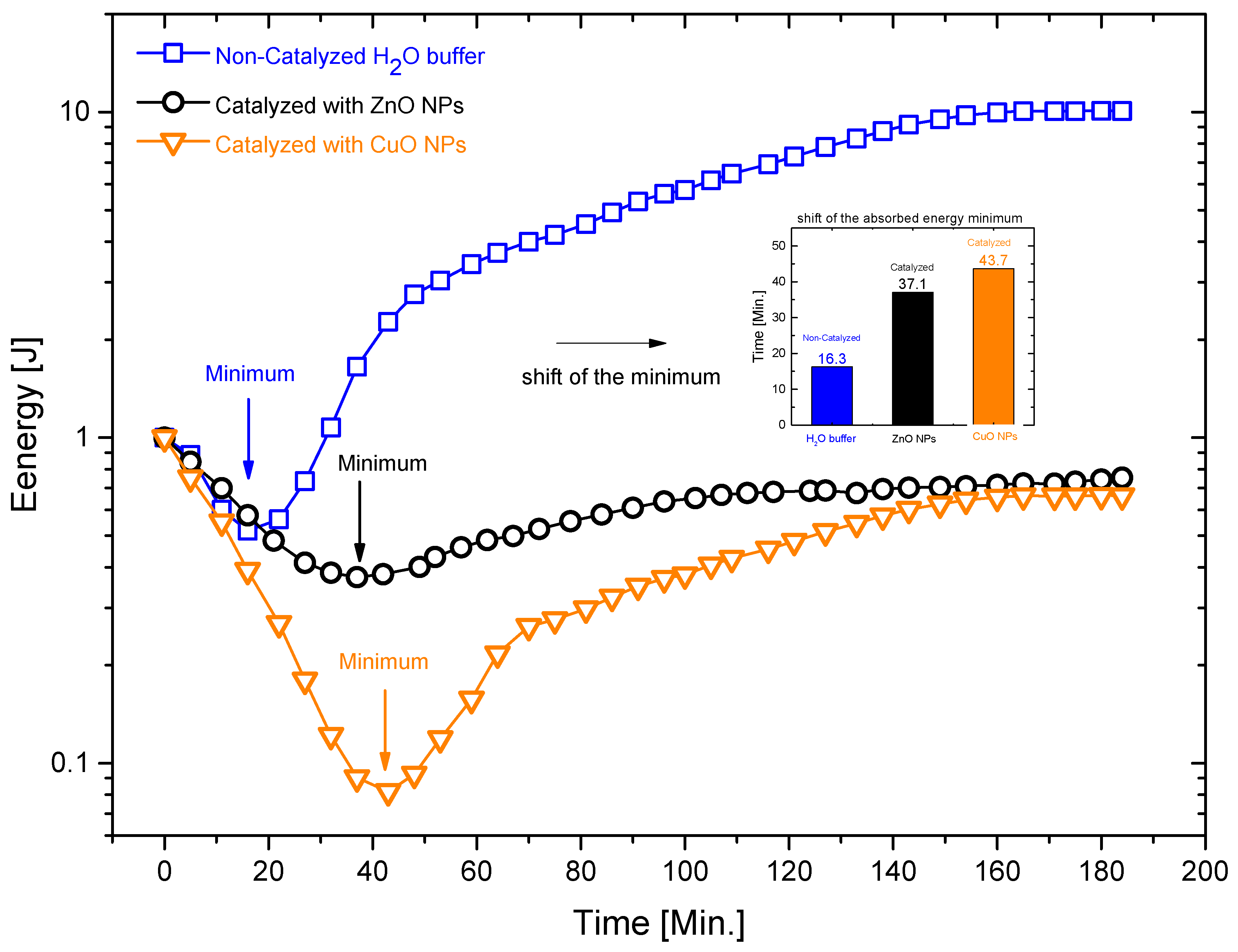
Figure 10 shows the input energy versus the period of time for the three systems calculated based on the applied voltage and induced electrical currents. The input energy curves show similar characteristic behaviors; all of them have minimum value after a steep decrease in the absorbance curve. Then the curves proceed slowly toward the asymptotic approach. Interestingly, the position of the minimum value appeared to be associated with a time delay, as indicated in the inset plot in
Figure 10. The minimum value in the curve in the system catalyzed with CuO NPs appeared at the latest in the time scale, while it appeared at the earliest in the non-catalyzed system. This behavior can be associated with the chemical reactivity and the intermediate oxide generated during the electrochemical reactions. The more reactive the system, the longer time it needs until it reaches chemical stability. The applied voltage is set to a constant value. Therefore, the conductivity is the driving force for the electrical current and eventually the input power. The absorbed energy (work done by current in a resistive media) does not show a linear proportionality to the current at a fixed voltage, indicating that all of the systems have non-ohmic behaviors. The initial energies were normalized to unity offset to compare the three samples together (
Figure 8).
Additionally, the curve of input energy for the system performed with CuO NPs has a lower magnitude compared to that for the other systems. Additionally, the peak of the system performed with ZnO NPs is broader than that for the non-catalyzed system and the one with CuO NPs indicating that the electrochemical reaction (water splitting) is slow. The non-catalyzed system shows the slowest electrochemical reaction, and the highest energy accumulates in the form of heat.
3.8. Dissipated and Splitting Energies
The calculations of the input, dissipated, and splitting energies of the three systems as well as the normalized efficiency with respect to the maximum value in each system were investigated according to the following formulation and assumptions. The efficiency of the system was predicted based on the calculated energies over the full period of the operation, the relevant energies of the splitting with respect to the input energies for every system. Hence, the input energy (
) in Joules (the input electrical energy in the system) is usually calculated according to Equation (1) (
). This formula can be used only for constant currents and voltages. The electrical current in the electrolysis process in non-constant pattern as shown in
Figure 5. Therefore, the energy can be calculated as:
The calculations of the integration of the current was calculated by using the Origin Lab Software. The dissipated energies of the three systems are the thermal energies that are spent to raise the system temperature from the starting temperature (ambient temperature) to the final temperature of the system. The systems (the reactor) consist of the buffer solution, which is mainly water, and it was formed with 380 mL for all of the measurements of the additive water solutions to calibrate the pH. An 11 mL glass beaker is also involved in absorbing part of the thermal energy and its mass was found to be 0.360 Kg. The two BDD mesh electrodes along with their connections and spacer are also involved in absorbing thermal energy and their total mass was found to be 0.412 kg and it is considered as stainless steel since the thin layer of BDD is negligible compared to the mass of the substrate. The dissipated thermal energy (
) for every system is the sum of the thermal energies of the components such as:
The masses were measured in kilogram and found to be ( The specific heat capacities (c) are; .
The change in temperature from ambient and the temperature of the solution (ΔT) were measured in degrees Celsius (°C) for every time of increment.
The corresponding energy used to evaporate water from the surface was calculated based on calculating the amount of evaporated water such as:
where
= amount of evaporated water per hour (kg/h),
θ,
υ = velocity of air above the surface of the water (m/s). The velocity was considered to be zero,
A = water surface area (m
2),
= maximum humidity ratio of saturated air at the same as temperature at the surface of the water (H
2O in kg dry air), and
= humidity ratio of air (H
2O in kg dry air).
v is set to zero (inside the reactor no air flow) and the area of the beaker surface is (π
r2 = π (0.1)
2) = 0.0314 m
2. The parameters
= 0.025 in the lab area,
= 0.009 in the lab, as well as the time measurements and the evaporation coefficient
θ = 25 + 19 (0 m/s) = 25 kg/m
2h are all considered.
The equivalent evaporation energies were calculated as:
, where i = system 1 (non-catalyzed), system 2 (catalyzed with CuO NPs, and system 3 (catalyzed with ZnO NPs). is the highest efficiency of one of the systems.
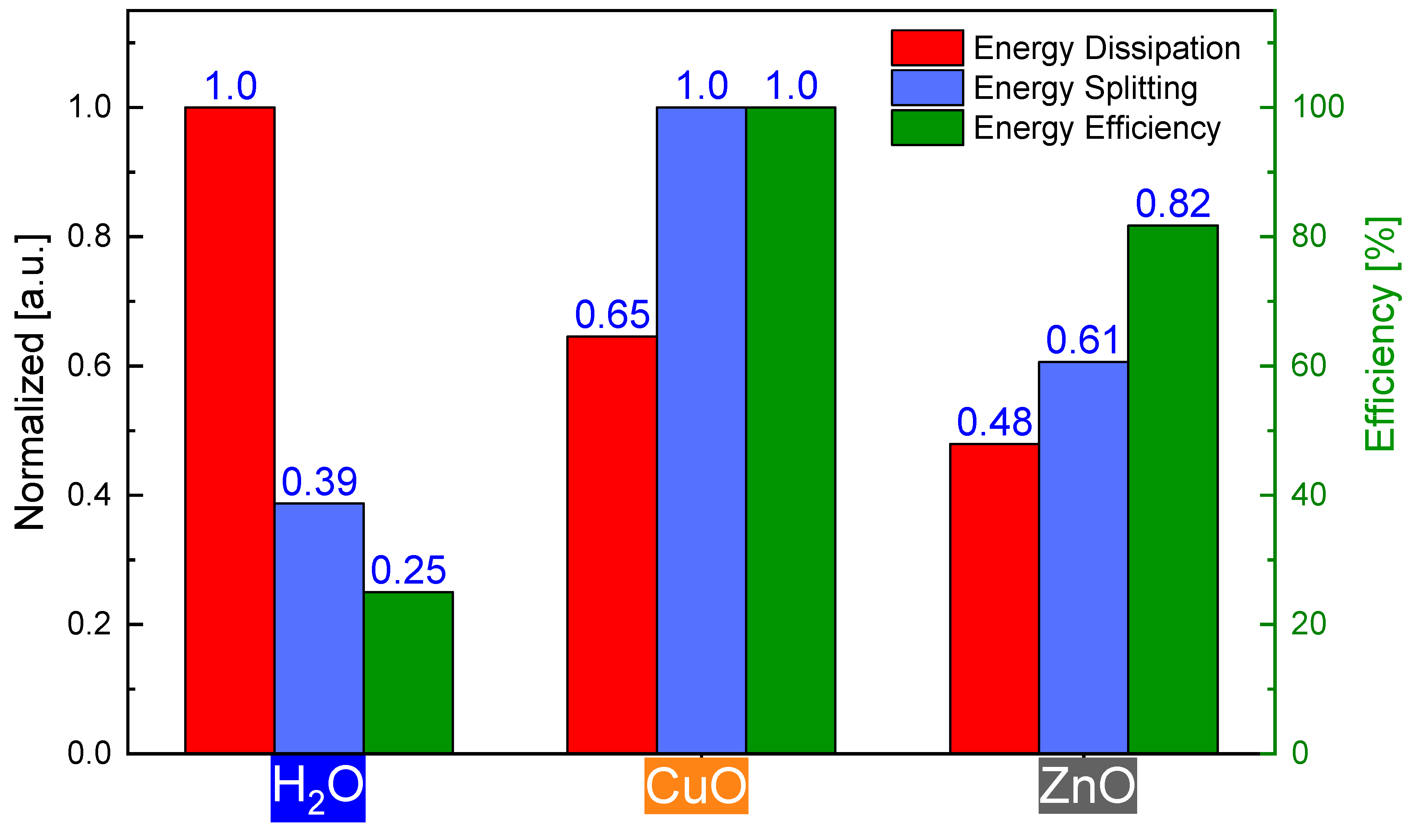
Figure 11 shows the normalized dissipated and splitting energies as well as the efficiency of the overall splitting energy rates in J/s for the non- and catalyzed systems. The dissipated energy of the non-catalyzed system is the highest compared to those of the systems with CuO NPs, and ZnO NPs and the normalized dissipated energies are 0.65 and 0.48, respectively. The splitting energies of the non-catalyzed system and the system performed with ZnO NPs are 0.39 and 0.6, respectively compared to the normalized system performed with CuO NPs (normalization to the unit because it has the highest magnitude). The overall efficiency in the non-catalyzed system and the one catalyzed with ZnO NPs are 0.25 and 0.82, respectively, compared to that for the normalized system catalyzed with CuO NPs.
As a conclusion, CuO NPs as splitting catalysts in the electrochemical splitting process demonstrate the best performance under the applied experimental parameters while employing the BDD/Nb electrodes.
4. Conclusions
A catalytic electrochemical water splitting process using a boron-doped diamond (BDD/Nb) electrode in the electrochemical reactor was investigated in terms of the electrical current, acidity (pH), electrical conductivity, absorption, dissipation and splitting energies, and the efficiency of the electrochemical water splitting process.
The electrical current of the non-catalyzed system is attributed to the increases increasing the in the effective electrical conductivity. The electrical current trends of the systems performed with CuO NPs and ZnO NPs are similar to each other and they reflect the conductivity curve trends indicating that the mechanism of the electrical conductivity is driven by the vehicle mechanism of ionic charge transportation.
The acidity of the catalyzed and non-catalyzed systems suffers from shifting towards the basicity situation during the electrochemical splitting. This might be attributed to fact that generating different metal oxides such as Cu2O or forming heterogeneous nanoparticles changes the acidity level.
The dissipated energy of the non-catalyzed system is the highest compared to those for the systems catalyzed with CuO NPs and ZnO NPs. This shows normalized dissipated energies with the values of 0.65 and 0.48, respectively, compared to the normalized one for unity for the non-catalyzed system. The splitting energies of the non-catalyzed system and the system prepared with ZnO NPs are 0.39 and 0.61, respectively, compared to that for the normalized system prepared with CuO NPs (normalization to the unit because it has the highest magnitude). The overall efficiency in water and ZnO is 0.25 and 0.82, respectively, compared to that for the normalized system prepared with CuO NPs. Based on the comparative information, the electrochemical water splitting catalyzed prepared with CuO NPs exhibited the best performance under the experimental parameters in using BDD/Nb electrodes. Based on our findings, solar power can be used to drive the efficient catalytic electrochemical water splitting by using BDD/Nb electrodes in order to produce hydrogen gas which can be used directly as a fuel in hydrogen internal combustion engines, as well as in proton exchange membrane fuel cells (PEMFCs). It may also be indirectly used for producing methanol through methanol synthesis from CO2 hydrogenation and then using methanol in direct methanol fuel-cells (DMFCs).
Author Contributions
Conceptualization, Y.A.-A., I.J., R.J., H.G., and A.T.; methodology, Y.A.-A., I.J., R.J., H.G., and A.T.; validation, Y.A.-A., I.J., R.J., H.G., and A.T.; formal analysis, Y.A.-A., I.J., R.J., H.G., and A.T.; investigation, Y.A.-A., I.J., R.J., H.G., and A.T.; writing (original draft preparation), Y.A.-A.; writing (review and editing), Y.A.-A., I.J., R.J., H.G., and A.T.; visualization, I.J. and, R.J.; supervision, A.T. and I.J.; project administration, Y.A.-A.; funding acquisition, Y.A.-A. All authors have read and agreed to the published version of the manuscript.
Funding
The authors are thankful for the fund provided by the deanship of research scientific at the University of Jordan. The funding for all used equipment was from a project called “Three-stage solar powered integrated catalytic water splitter into the production of methanol from CO2 and H2 along with Direct Methanol Fuel Cell (DMFC) as a collective solution for high efficiency energy production-storage plant”.
Acknowledgments
The authors would like to thank the Deanship of Research and Development at Jordan University, Amman, Jordan, to support this work. The authors gratefully acknowledge the Institute of Metals Science and Technology (WTM) (Stefan M. Rosiwal, Friedrich-Alexander University, Erlangen. Germany for use of the HF-CVD and Raman microscopy and for the technical assistance with measurements.
Conflicts of Interest
The authors declare no conflict of interest.
References
- Abdelsalam, E.; Kafiah, F.M.; Alkasrawi, M.; Al-Hinti, I.; Azzam, A. Economic Study of Solar Chimney Power-Water Distillation Plant (SCPWDP). Energies 2020, 13, 2789. [Google Scholar] [CrossRef]
- Yan, Y.; He, T.; Zhao, B.; Qi, K.; Liu, H.; Xia, B.Y. Metal/covalent-organic frameworks-based electrocatalysts for water splitting. J. Mater. Chem. A 2018, 6, 15905–15926. [Google Scholar] [CrossRef]
- Liu, Y.; Dong, Y.; Tang, Z.; Wang, X.; Wang, L.; Hou, T.; Lin, H.; Li, Y. Stable and metallic borophene nanoribbons from first-principles calculations. J. Mater. Chem. C 2016, 4, 6380–6385. [Google Scholar] [CrossRef]
- Huang, D.; Chen, S.; Niu, C.G.; Gong, X.; Zhou, C.; Cheng, M.; Xue, W.; Yan, X.; Li, J. Artificial Z-scheme photocatalytic system: What have been done and where to go? Coord. Chem. Rev. 2019, 385, 44–80. [Google Scholar] [CrossRef]
- Staffell, I.; Scamman, D.; Abad, A.V.; Balcombe, P.; Dodds, P.E.; Ekins, P.; Shah, N.; Ward, K.R. The role of hydrogen and fuel cells in the global energy system. Energy Environ. Sci. 2019, 12, 463–491. [Google Scholar] [CrossRef] [Green Version]
- Bhosale, R.R.; Sutar, P.; Kumar, A.; Almomani, F.; Ali, M.H.; Ghosh, U.K.; Khraisheh, M.; Al-Muhtaseb, S. Solar hydrogen production via erbium oxide based thermochemical water splitting cycle. J. Renew. Sustain. Energy 2016, 8, 034702. [Google Scholar] [CrossRef]
- Chen, L.; Dong, X.; Wang, Y.; Xia, Y. Separating hydrogen and oxygen evolution in alkaline water electrolysis using nickel hydroxide. Nat. Commun. 2016, 7, 11741. [Google Scholar] [CrossRef] [PubMed]
- Panizza, M.; Michaud, P.; Cerisola, G.; Comninellis, C. Electrochemical treatment of wastewaters containing organic pollutants on boron-doped diamond electrodes: Prediction of specific energy consumption and required electrode area. Electrochem. Commun. 2001, 3, 336–339. [Google Scholar] [CrossRef]
- Powar, N.; Pandav, R. Overview of Borophene as a Potential Candidate in 2D Materials Science for the Energy Applications. J. Chem. Rev. 2019, 1, 271–281. [Google Scholar] [CrossRef] [Green Version]
- Fujishima, A.; Honda, K. Electrochemical Photolysis of Water at a Semiconductor Electrode. Nature 1972, 238, 37–38. [Google Scholar] [CrossRef]
- Simon, Q.; Barreca, D.; Gasparotto, A.; Maccato, C.; Montini, T.; Gombac, V.; Fornasiero, P.; Lebedev, O.I.; Turner, S.; van Tendeloo, G. Vertically oriented CuO/ZnO nanorod arrays: From plasma-assisted synthesis to photocatalytic H2 production. J. Mater. Chem. 2012, 22, 11739–11747. [Google Scholar] [CrossRef]
- Zhang, Q.; Zhang, K.; Xu, D.; Yang, G.; Huang, H.; Nie, F.; Liu, C.; Yang, S. CuO nanostructures: Synthesis, characterization, growth mechanisms, fundamental properties, and applications. Prog. Mater. Sci. 2014, 60, 208–337. [Google Scholar] [CrossRef]
- Roeser, J.; Alting, N.F.A.; Permentier, H.P.; Bruins, A.P.; Bischoff, R. Boron-Doped Diamond Electrodes for the Electrochemical Oxidation and Cleavage of Peptides. Anal. Chem. 2013, 85, 6626–6632. [Google Scholar] [CrossRef] [PubMed]
- Gerger, I.; Haubner, R.; Kronberger, H.; Fafilek, G. Investigation of diamond coatings on titanium substrates for electrochemical applications. Diam. Relat. Mater. 2004, 13, 1062–1069. [Google Scholar] [CrossRef]
- Zhi, J.F.; Wang, H.B.; Nakashima, T.; Rao, T.N.; Fujishima, A. Electrochemical Incineration of Organic Pollutants on Boron-Doped Diamond Electrode. Evidence for Direct Electrochemical Oxidation Pathway. J. Phys. Chem. B 2003, 107, 13389–13395. [Google Scholar] [CrossRef]
- Gandini, D.; Mahé, E.; Michaud, P.; Haenni, W.; Perret, A.; Comninellis, C. Oxidation of carboxylic acids at boron-doped diamond electrodes for wastewater treatment. J. Appl. Electrochem. 2000, 30, 1345–1350. [Google Scholar] [CrossRef]
- Reier, T.; Pawolek, Z.; Cherevko, S.; Bruns, M.; Jones, T.; Teschner, D.; Selve, S.; Bergmann, A.; Nong, H.N.; Schlogl, R.; et al. Molecular Insight in Structure and Activity of Highly Efficient, Low-Ir Ir–Ni Oxide Catalysts for Electrochemical Water Splitting (OER). J. Am. Chem. Soc. 2015, 137, 13031. [Google Scholar] [CrossRef]
- Nong, H.N.; Gan, L.; Willinger, E.; Teschner, D.; Strasser, P. IrOx core-shell nanocatalysts for cost- and energy-efficient electrochemical water splitting. Chem. Sci. 2014, 5, 2955–2963. [Google Scholar] [CrossRef] [Green Version]
- Banerjee, A.; Chakraborty, S.; Jena, N.K.; Ahuja, R. Scrupulous Probing of Bifunctional Catalytic Activity of Borophene Monolayer: Mapping Reaction Coordinate with Charge Transfer. ACS Appl. Energy Mater. 2018, 1, 3571–3576. [Google Scholar] [CrossRef]
- Ardizzone, S.; Bianchi, C.L.; Cappelletti, G.; Ionita, M.; Minguzzi, A.; Rondinini, S.; Vertova, A. Composite ternary SnO2–IrO2–Ta2O5 oxide electrocatalysts. J. Electroanal. Chem. 2006, 589, 160. [Google Scholar] [CrossRef]
- Wang, S.; Gao, S.; Tian, J.; Wang, Q.; Wang, T.; Hao, X.; Cui, F. A stable and easily prepared copper oxide catalyst for degradation of organic pollutants by peroxymonosulfate activation. J. Hazard. Mater. 2020, 387, 121995. [Google Scholar] [CrossRef] [PubMed]
- Abdelhay, A.; Jum’h, I.; Abdulhay, E.; Al-Kazwini, A.; Alzubi, M. Anodic oxidation of slaughterhouse wastewater on boron-doped diamond: Process variables effect. Water Sci. Technol. 2017, 76, 3227–3235. [Google Scholar] [CrossRef] [PubMed]
- Jum’h, I.; Al-Addous, M.; Al-Taani, H.; El-Sadik, M.S.A.; Ayoub, N. Effect of boron concentration on nano-crystalline diamond deposited on niobium substrates. Dig. J. Nanomater. Biostruct. 2017, 12, 589–593. [Google Scholar]
- Jum’h, I.; Abdelhay, A.; Telfah, A.; Al-Akhras, M.A.; Al-Kazwini, A.; Rosiwal, S. Veratric acid removal from water by electrochemical oxidation on BDD anode. IOP Conference Series: Materials Science and Engineering, Volume 305. In Proceedings of the 2nd International Conference on Advanced Materials (ICAM-2017), Irbid, Jordan, 10–13 July 2017. [Google Scholar]
- Jum’h, I.; Abdelhay, A.; Al-Taani, H.; Telfah, A.; Alnaief, M.; Rosiwal, S. Fabrication and application of boron doped diamond BDD electrode in olive mill wastewater treatment in Jordan. J. Water Reuse Desalin. 2016, 7, 502–510. [Google Scholar] [CrossRef]
- Jiang, J.; Chang, M.; Pan, P. Simultaneous Hydrogen Production and Electrochemical Oxidation of Organics using Boron-Doped Diamond Electrodes. Environ. Sci. Technol. 2008, 42, 3059–3063. [Google Scholar] [CrossRef]
- Ashcheulov, P.; Taylor, A.; Mortet, V.; Poruba, A.; Le Formal, F.; Krýsová, H.; Klementova, M.; Hubik, P.; Kopeček, J.; Lorincik, J.; et al. Nanocrystalline Boron-Doped Diamond as a Corrosion-Resistant Anode for Water Oxidation via Si Photoelectrodes. ACS Appl. Mater. Interfaces 2018, 10, 29552–29564. [Google Scholar] [CrossRef]
- Surovtsev, N.V.; Kupriyanov, I.N. Effect of Nitrogen Impurities on the Raman Line Width in Diamond, Revisited. Crystals 2017, 7, 239. [Google Scholar] [CrossRef] [Green Version]
- Kreuer, K.D.; Rabenau, A.; Weppner, W. Vehicle Mechanism, A New Model for the Interpretation of the Conductivity of Fast Proton Conductors. Angew. Chem. Int. Ed. 1982, 21, 208–209. [Google Scholar] [CrossRef]
- Lim, D.W.; Sadakiyo, M.; Kitagawa, H. Proton transfer in hydrogen-bonded degenerate systems of water and ammonia in metal–organic frameworks. Chem. Sci. 2018, 10, 16–33. [Google Scholar] [CrossRef] [Green Version]
- Smith, K.C.A.; Alley, R.E. Electrical Circuits: An Introduction; Cambridge University Press: Cambridge, UK, 1992; pp. 11–13. ISBN 0-521-37769-2. [Google Scholar]
- Stillinger, F.H.; David, C.W. Polarization model for water and its ionic dissociation products. J. Chem. Phys. 1978, 69, 1473. [Google Scholar] [CrossRef] [Green Version]
- Totsche, O.; Fyson, A.; Kalin, M.; Steinberg, C. Titration curves: A useful instrument for assessing the buffer systems of acidic mining waters (10 pp). Environ. Sci. Pollut. Res. 2006, 13, 215–224. [Google Scholar] [CrossRef] [PubMed]
- Sue, K.; Usami, T.; Arai, K. Determination of Acetic Acid Dissociation Constants to 400 °C and 32 MPa by Potentiometric pH Measurements. J. Chem. Eng. Data 2003, 48, 1081–1084. [Google Scholar] [CrossRef]
© 2020 by the authors. Licensee MDPI, Basel, Switzerland. This article is an open access article distributed under the terms and conditions of the Creative Commons Attribution (CC BY) license (http://creativecommons.org/licenses/by/4.0/).


