A Variable Fractional Order Fuzzy Logic Control Based MPPT Technique for Improving Energy Conversion Efficiency of Thermoelectric Power Generator


Abstract
:1. Introduction
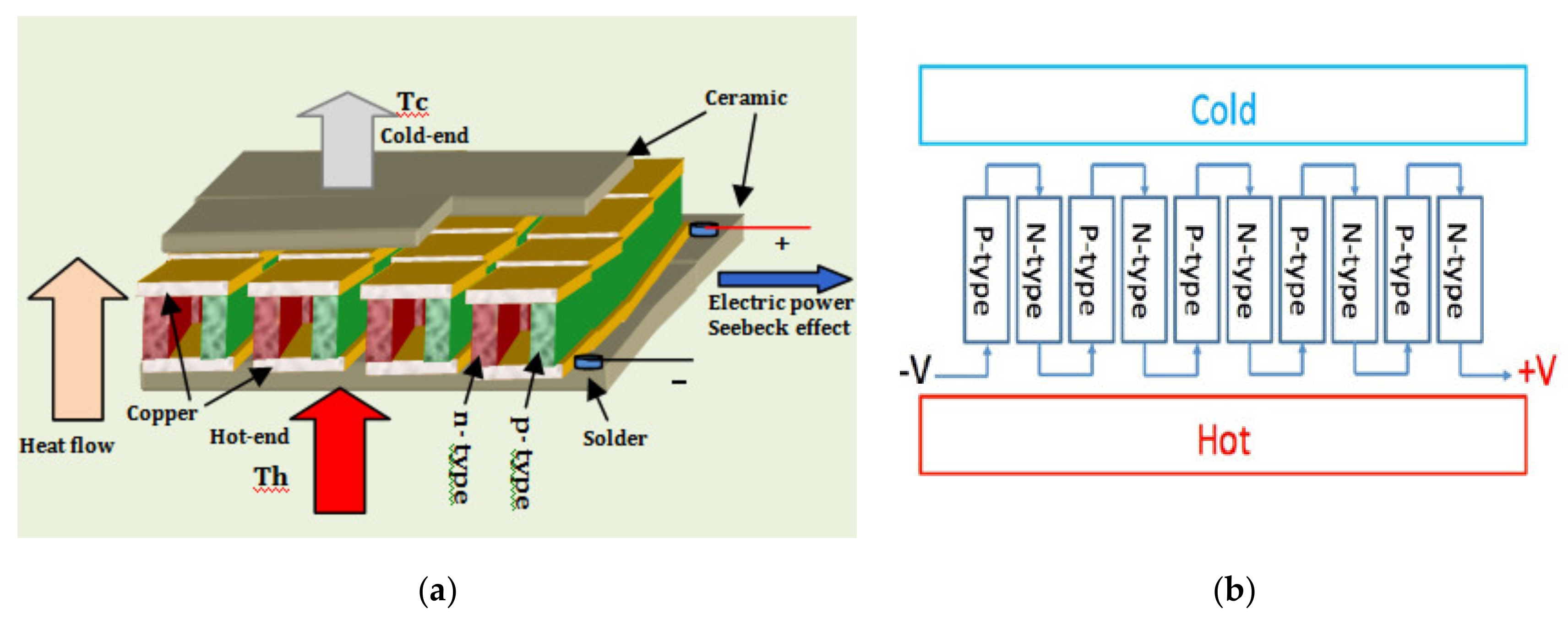
2. TEG Model
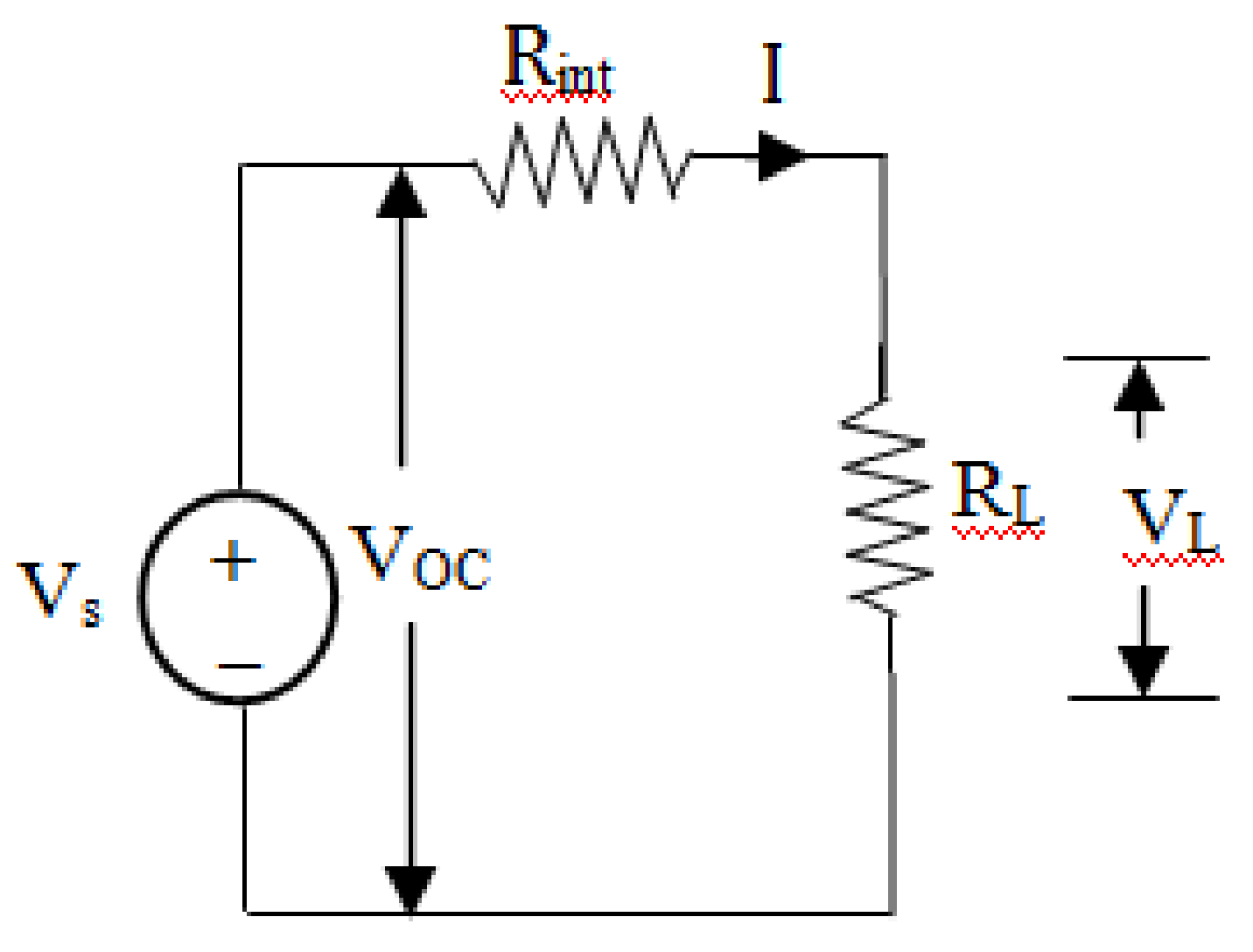
2.1. Modeling of the Thermoelectric Generator
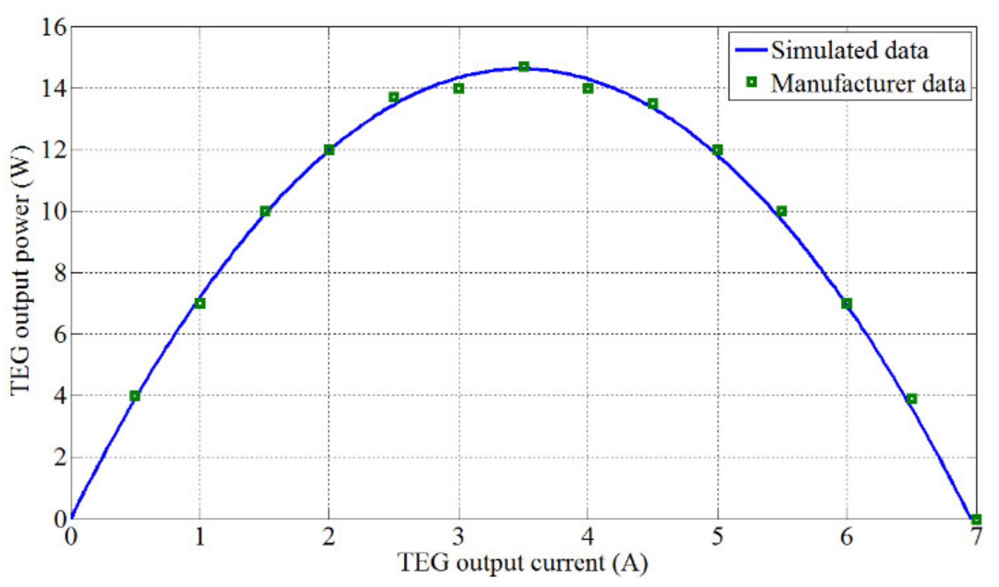
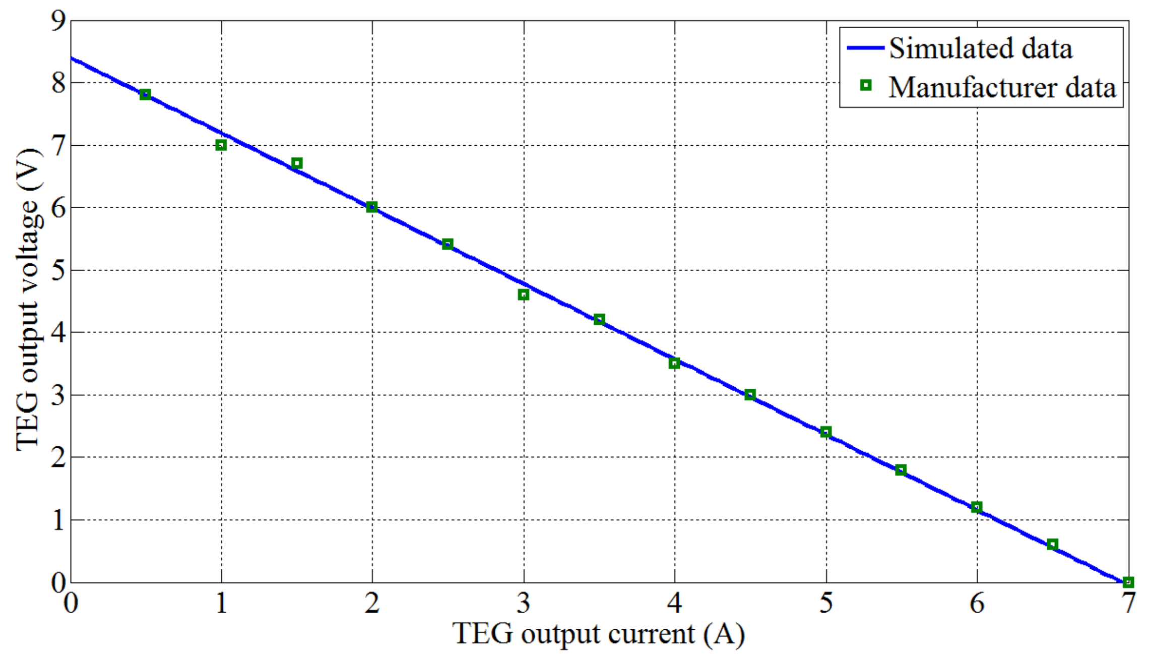
2.2. Model Validation
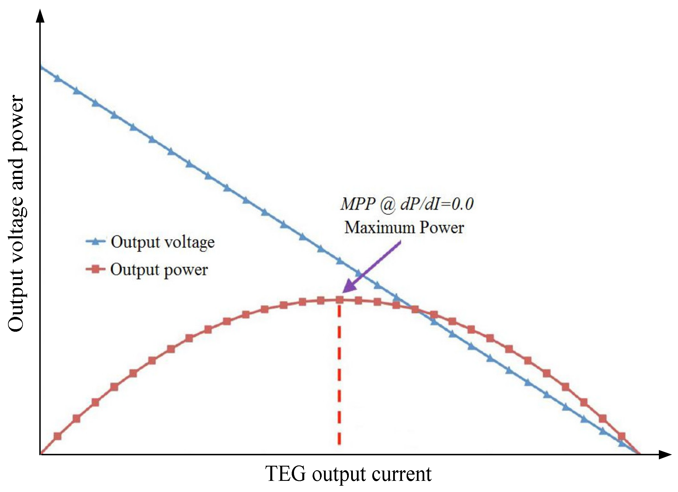
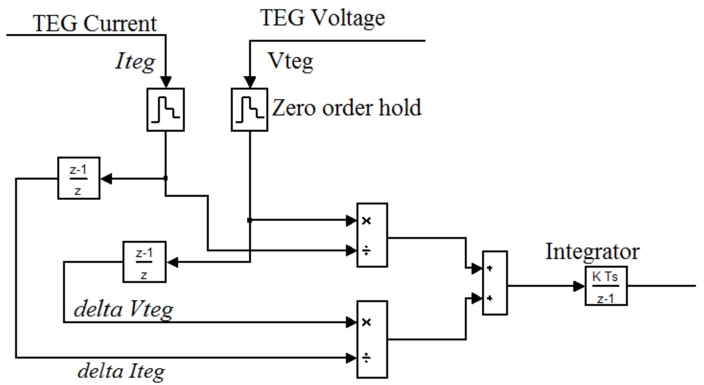
3. Incremental Resistance-Based MPPT Technique
4. Variable Fractional Order Fuzzy Logic Controller-Based MPPT Technique
4.1. Fractional Order Control
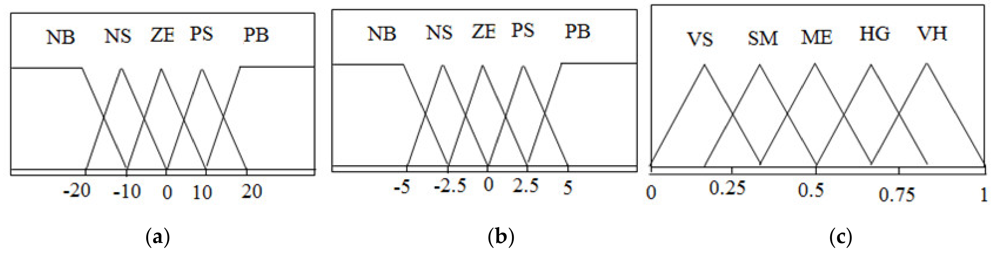
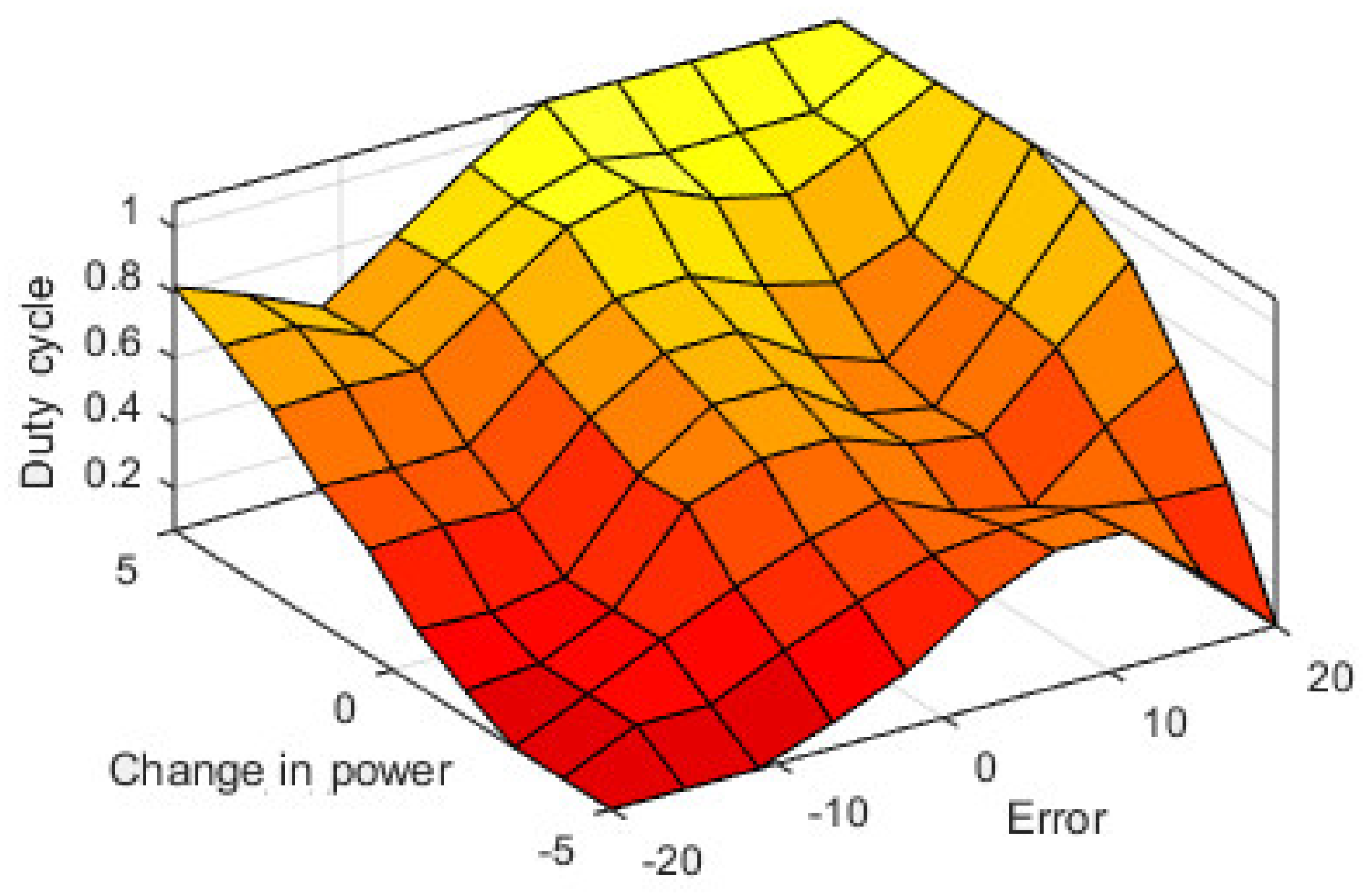
4.2. VFOFLC-Based MPPT Technique
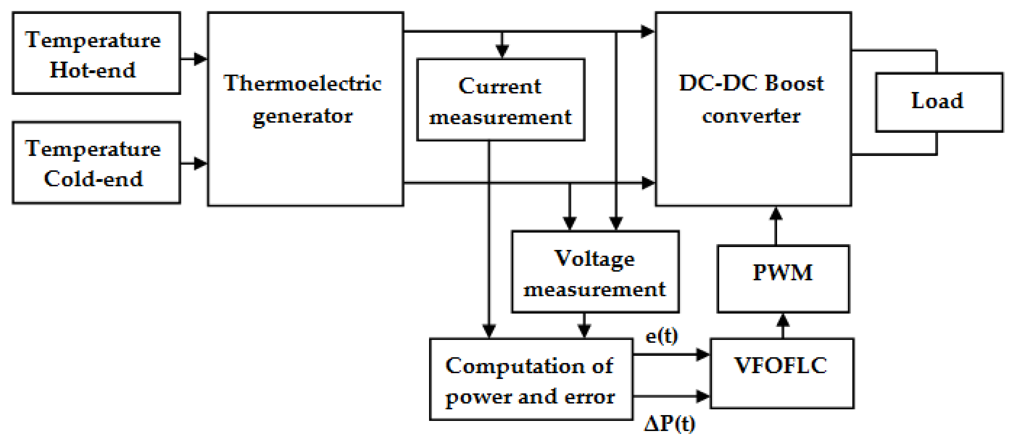
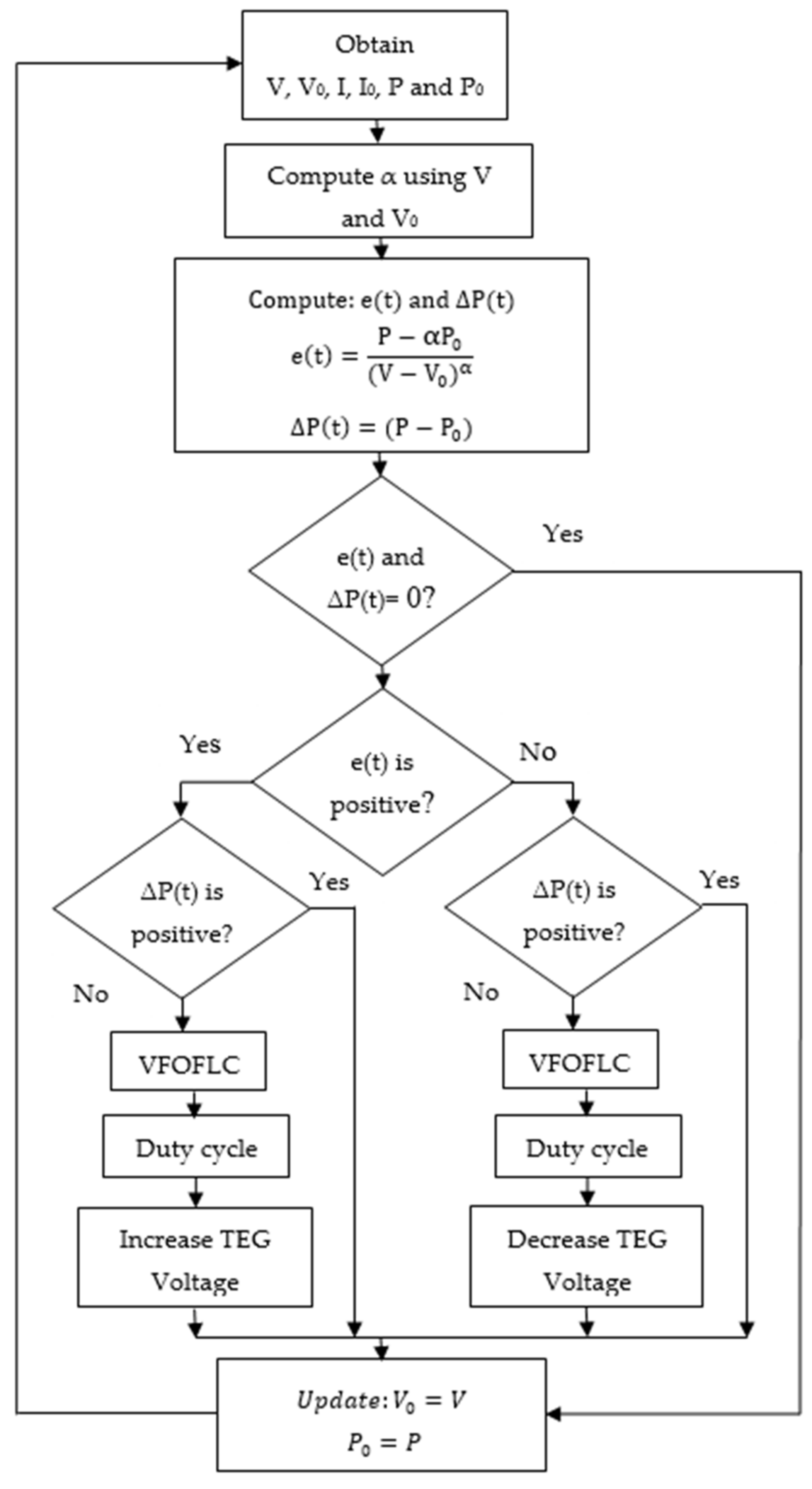
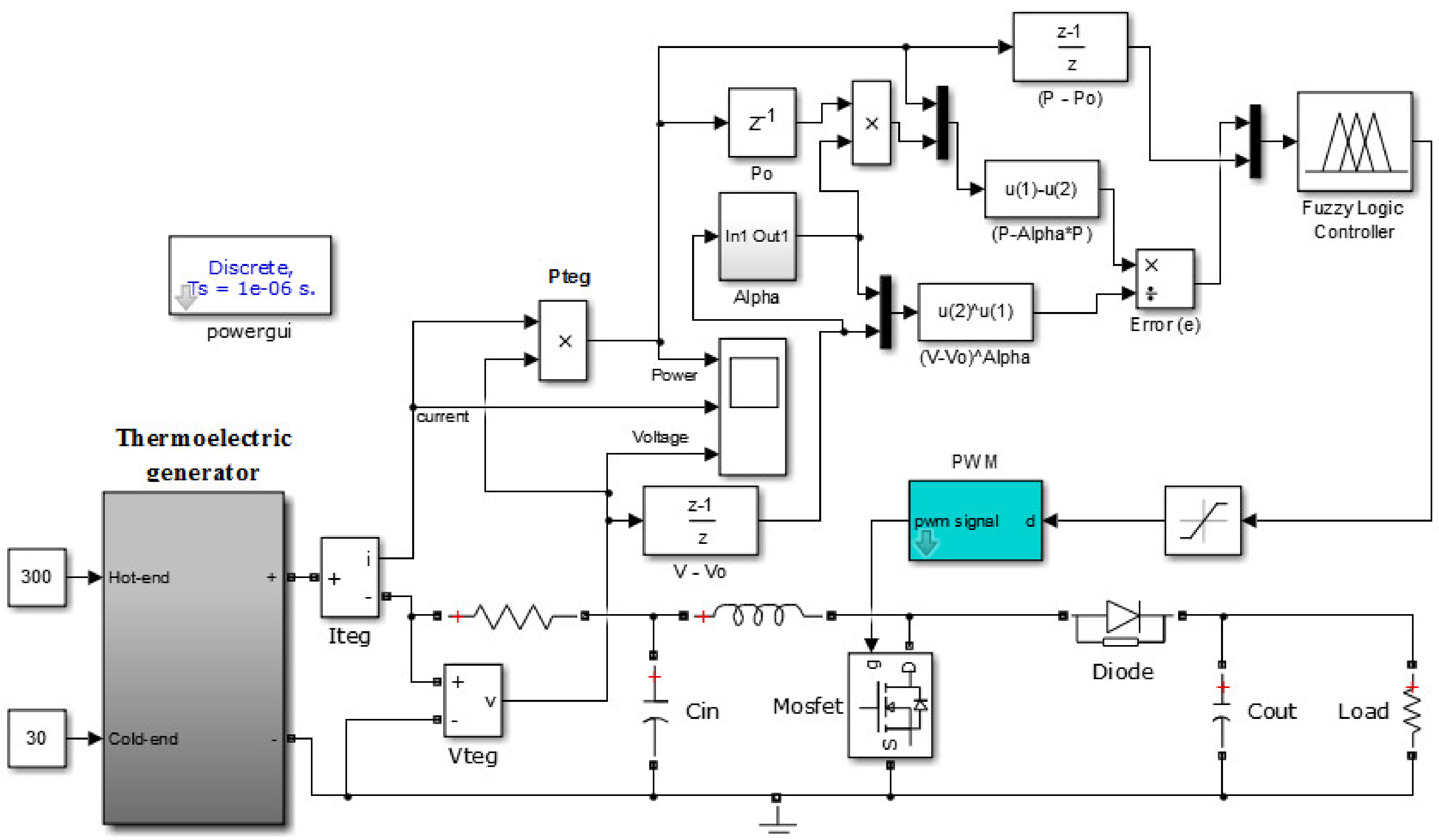
5. Implementation of the VFOFLC-Based MPPT Technique
6. Results and Discussion
6.1. Fractional Factor and FLC Variable Discourse Range
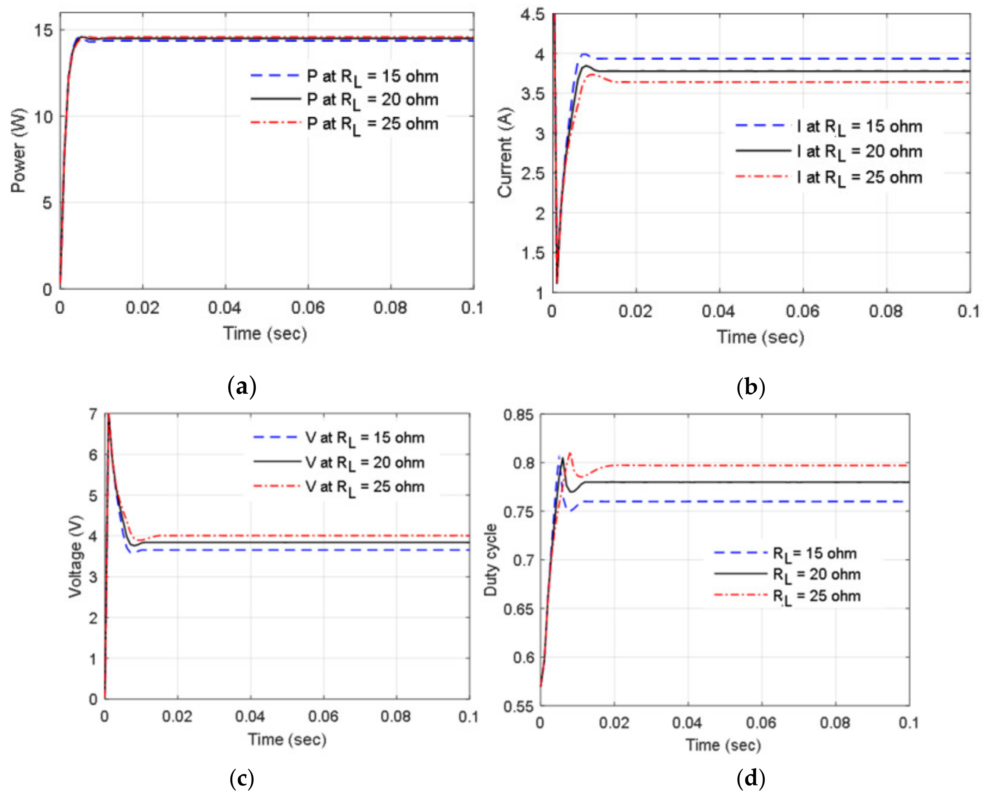
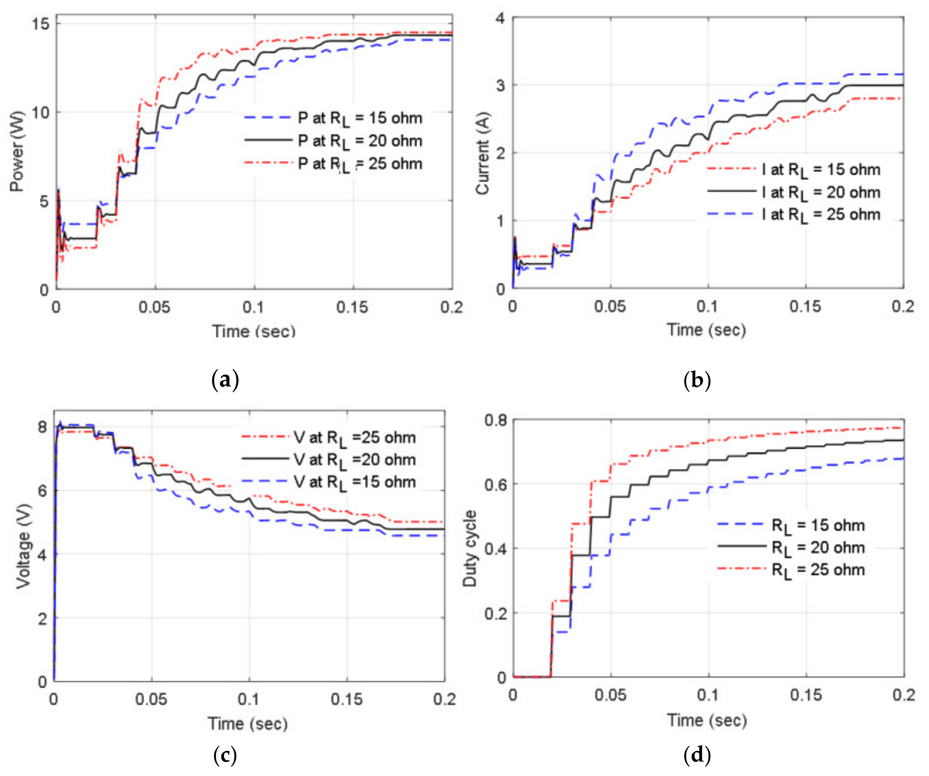
6.2. TEG Performance for Load Variation
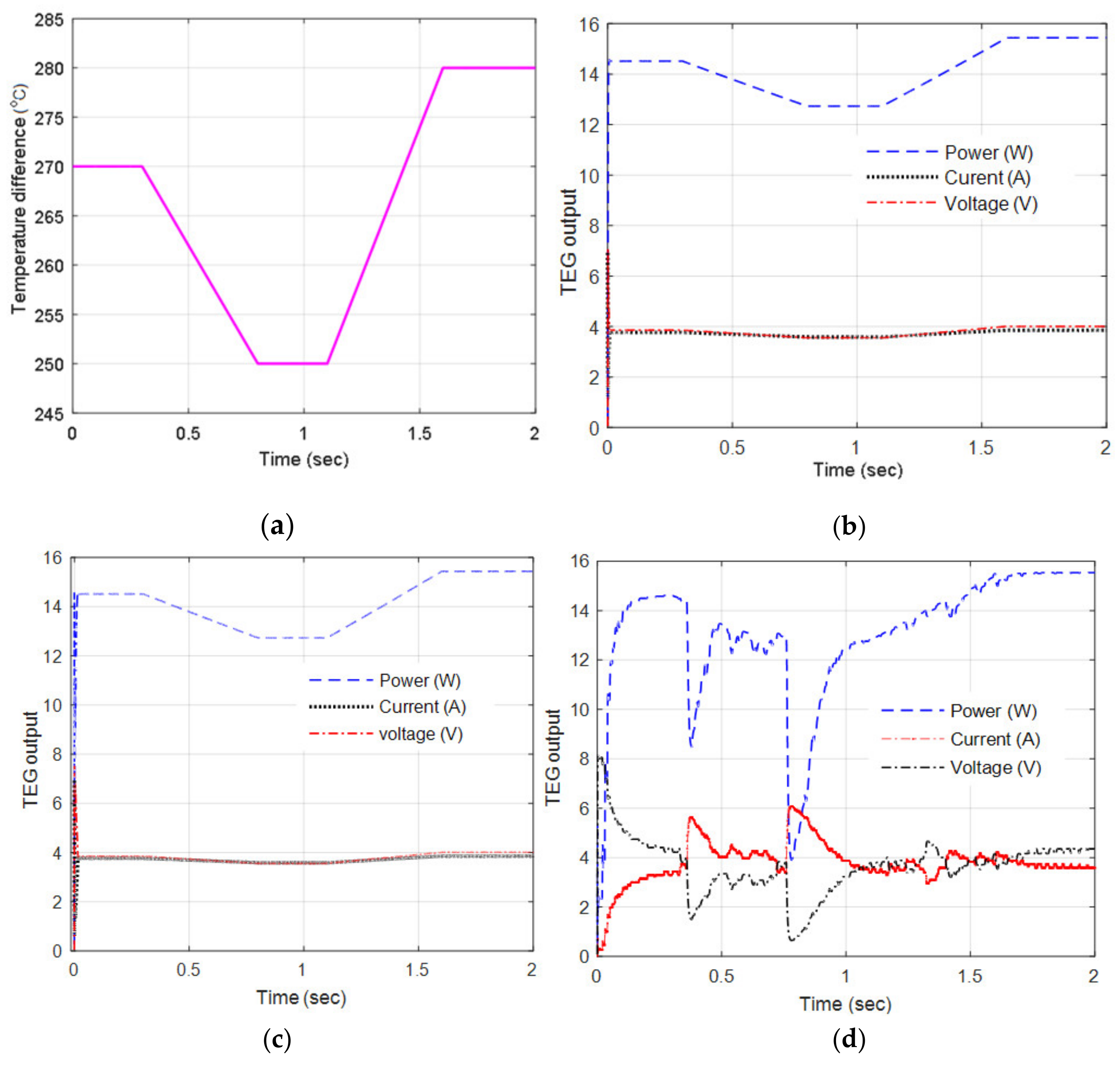
6.3. TEG Performance for Step Changes in Temperature
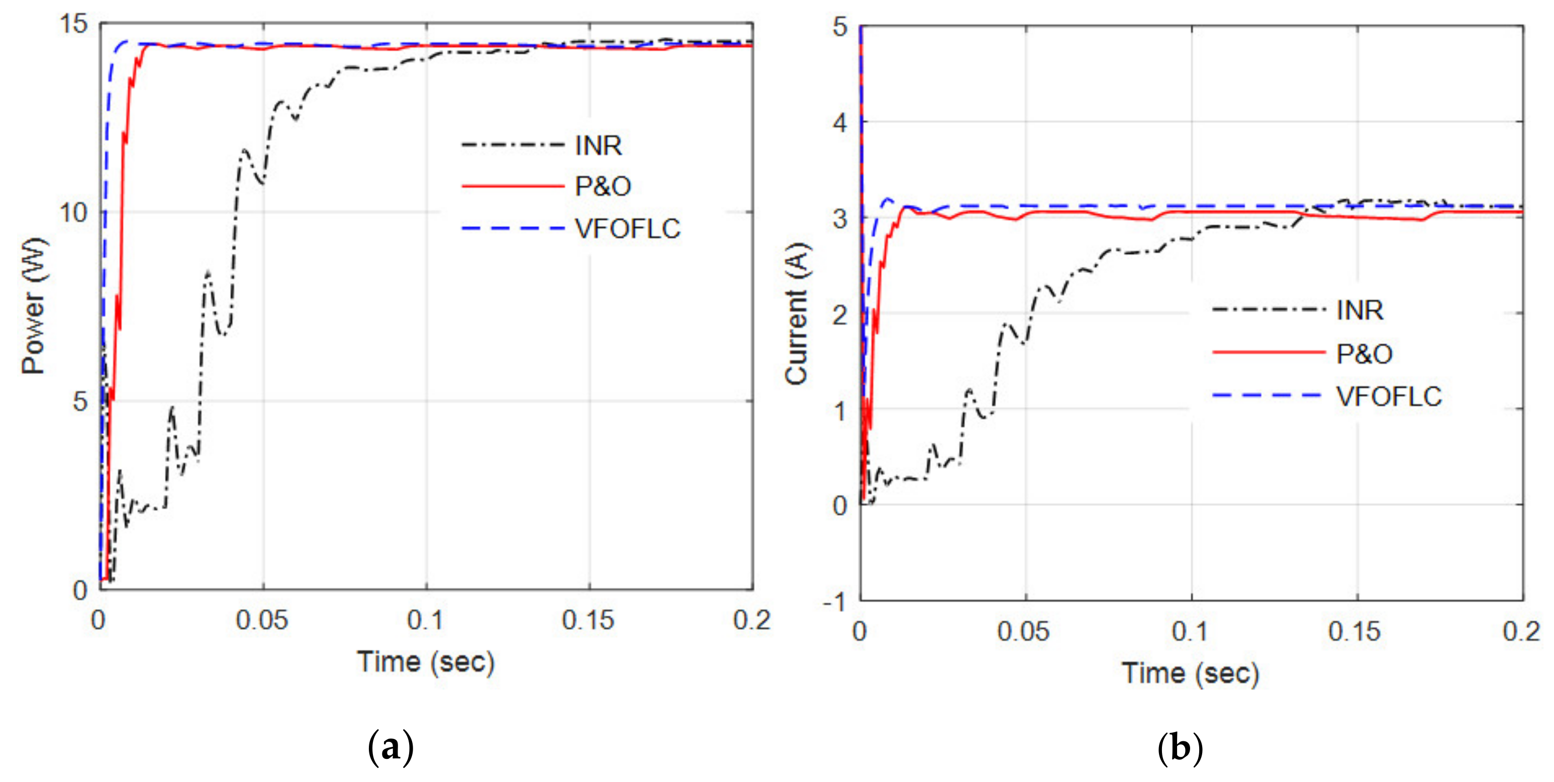
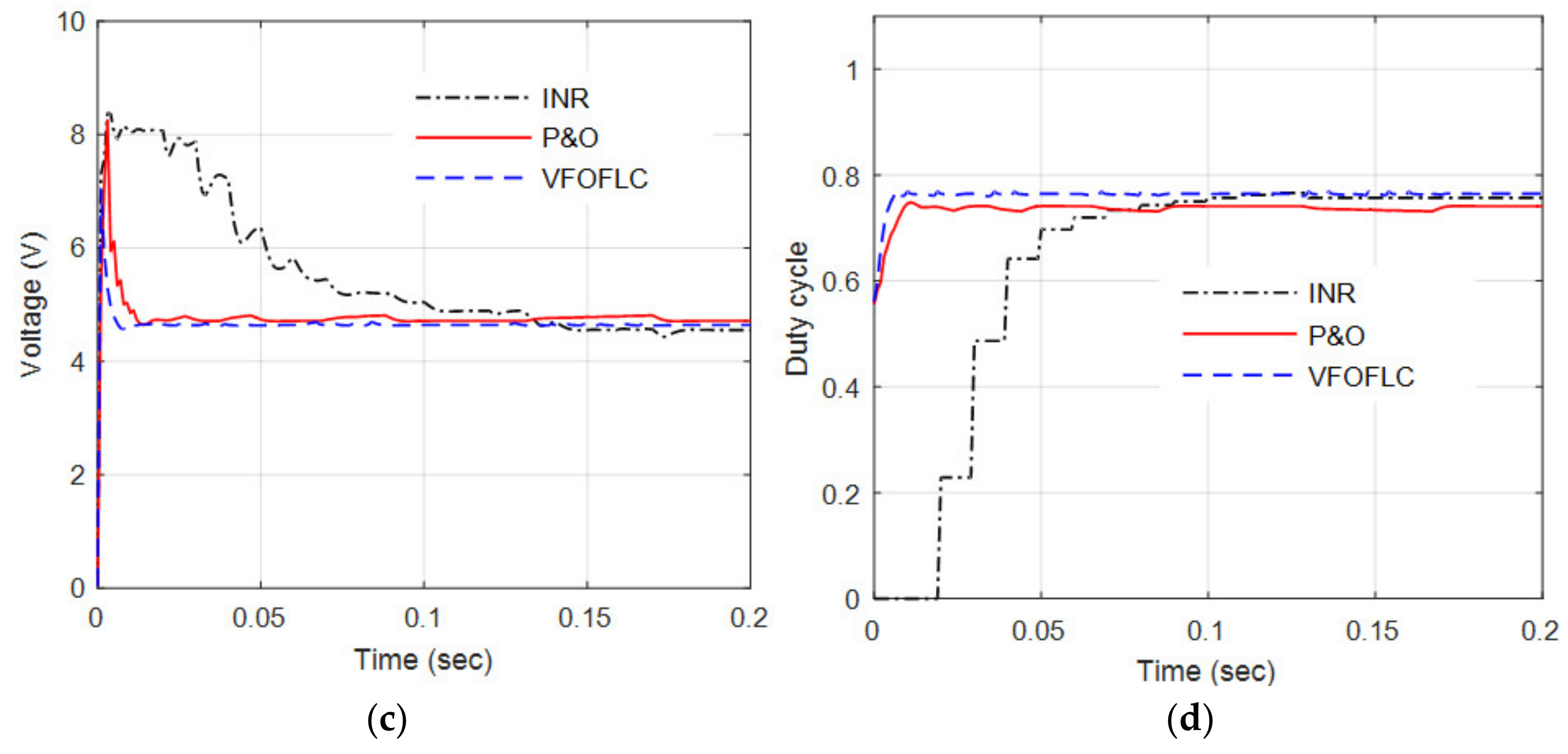
6.4. Performance Comparison for the Fixed Load and Temperature Difference
7. Conclusions
Author Contributions
Funding
Conflicts of Interest
References
- Twaha, S.; Zhu, J.; Yan, Y.; Li, B. A comprehensive review of thermoelectric technology: Materials, applications, modelling and performance improvement. Renew. Sustain. Energy Rev. 2016, 65, 698–726. [Google Scholar] [CrossRef]
- Roy, A.; Klinefelter, A.; Yahya, F.B.; Chen, X.; Gonzalez-Guerrero, L.P.; Lukas, C.J.; Kamakshi, D.A.; Boley, J.; Craig, K.; Faisal, M.; et al. A 6.45 μW self-powered SoC with integrated energy harvesting power management and ULP asymmetric radios for portable biomedical systems. IEEE Trans. Biomed. Circuits Syst. 2015, 9, 862–874. [Google Scholar] [CrossRef] [PubMed]
- Chen, J.; Klein, J.; Wu, Y.; Xing, S.; Flammang, R.; Heibel, M.; Zuo, L. A thermoelectric energy harvesting system for powering wireless sensors in nuclear power plants. IEEE Trans. Nucl. Sci. 2016, 63, 2738–2746. [Google Scholar] [CrossRef]
- Charris, D.; Gomez, D.; Ortega, A.R.; Carmona, M.; Pardo, M. A thermoelectric energy harvesting scheme with passive cooling for outdoor IoT sensors. Energies 2020, 13, 2782. [Google Scholar] [CrossRef]
- Dias, P.C.; Morais, F.J.O.; de Morais França, M.B.; Ferreira, E.C.; Cabot, A.; Dias, J.A.S. Autonomous multisensor system powered by a solar thermoelectric energy harvester with ultralow-power management circuit. IEEE Trans. Instrum. Meas. 2015, 64, 2918–2925. [Google Scholar] [CrossRef]
- Montecucco, A.; Knox, A.R. Maximum power point tracking converter based on the open-circuit voltage method for thermoelectric generators. IEEE Trans. Power Electron. 2015, 30, 828–839. [Google Scholar] [CrossRef]
- Yilbas, B.S.; Sahin, A.Z. Thermoelectric device and optimum external load parameter and slenderness ratio. Energy 2010, 35, 5380–5384. [Google Scholar] [CrossRef]
- Lesage, F.J.; Pelletier, R.; Fournier, L.; Sempels, E. Optimal electrical load for peak power of a thermoelectric module with a solar electric application. Energy Convers. Manag. 2013, 74, 51–59. [Google Scholar] [CrossRef]
- Kim, T.Y.; Negash, A.; Cho, G. Direct contact thermoelectric generator (DCTEG): A concept for removing the contact resistance between thermoelectric modules and heat source. Energy Convers. Manag. 2017, 142, 20–27. [Google Scholar] [CrossRef]
- Selvan, K.V.; Mohamed Ali, M.S. Copper–Nickel and Copper–Cobalt thermoelectric generators: Power-Generating optimization through structural geometrics. IEEE Trans. Electron Devices 2018, 65, 3394–3400. [Google Scholar] [CrossRef]
- Rezania, A.; Rosendahl, L.; Yin, H. Parametric optimization of thermoelectric elements footprint for maximum power generation. J. Power Sources 2014, 255, 151–156. [Google Scholar] [CrossRef]
- Ibrahim, A.; Rahnamayan, S.; Martin, M.V.; Yilbas, B.S. Multi-Objective thermal analysis of a thermoelectric device: Influence of geometric features on device characteristics. Energy 2014, 77, 305–317. [Google Scholar] [CrossRef]
- Jang, B.; Han, S.W.; Kim, S.W. Optimal design for micro-thermoelectric generators using finite element analysis. Microelectron. Eng. 2011, 88, 775–778. [Google Scholar] [CrossRef]
- Selvan, K.V.; Rehman, T.; Saleh, T.M.; Ali, M.S. Copper-Cobalt thermoelectric generators: Power improvement through optimized thickness and sandwiched planar structure. IEEE Trans. Electron Devices 2019, 66, 3459–3465. [Google Scholar] [CrossRef]
- Montecucco, A.; Knox, A. Accurate simulation of thermoelectric power generating systems. Appl. Energy 2014, 118, 166–172. [Google Scholar] [CrossRef]
- Meng, J.H.; Zhang, X.X.; Wang, X.D. Dynamic response characteristics of thermoelectric generator predicted by a three-dimensional heat-electricity coupled model. J. Power Sources 2014, 245, 262–269. [Google Scholar] [CrossRef]
- Chen, W.H.; Huang, S.R.; Wang, X.D.; Wu, P.H.; Lin, Y.L. Performance of a thermoelectric generator intensified by temperature oscillation. Energy 2017, 133, 257–269. [Google Scholar] [CrossRef]
- Kim, R.; Lai, J.; York, B.; Koran, A. Analysis and design of maximum power point tracking scheme for thermoelectric battery energy storage system. IEEE Trans. Ind. Electron 2009, 56, 3709–3716. [Google Scholar]
- Chandrarathna, S.C.; Lee, J. A dual-stage boost converter using two-dimensional adaptive input-sampling MPPT for thermoelectric energy harvesting. IEEE Trans. Circuits Syst. I 2019, 66, 4888–4900. [Google Scholar] [CrossRef]
- Bond, M.; Park, J. Current-Sensorless power estimation and MPPT implementation for thermoelectric generators. IEEE Trans. Ind. Electron. 2015, 62, 5539–5548. [Google Scholar] [CrossRef]
- Kim, J.; Kim, C. A DC–DC boost converter with variation-tolerant MPPT technique and efficient ZCS circuit for thermoelectric energy harvesting applications. IEEE Trans. Power Electron. 2013, 28, 3827–3833. [Google Scholar] [CrossRef]
- Bijukumar, B.; Raam, A.G.K.; Ganesan, S.I.; Nagamani, C. A linear extrapolation-based MPPT algorithm for thermoelectric generators under dynamically varying temperature conditions. IEEE Trans. Energy Convers. 2018, 33, 1641–1649. [Google Scholar] [CrossRef]
- Veerachacy, M.; Senjyu, T.; Uezato, K. Neural-Network-based maximum-power-point tracking of coupled-inductor interleaved-boost converter-supplied PV system using fuzzy controller. IEEE Trans. Ind. Electron. 2003, 50, 749–758. [Google Scholar] [CrossRef] [Green Version]
- Rezk, H.; Eltamaly, A.M. A comprehensive comparison of different MPPT techniques for photovoltaic systems. Sol. Energy 2015, 112, 1–11. [Google Scholar] [CrossRef]
- Ibrahim, H.E.; Houssiny, F.F. Microcomputer controlled buck regulator for maximum power point tracker for dc pumping system operates from photovoltaic system. In Proceedings of the IEEE International Fuzzy Systems Conference, Seoul, Korea, 22–25 August 1999; 1, pp. 406–411. [Google Scholar]
- Tan, B.; Ke, X.; Tang, D.; Yin, S. Improved perturb and observation method based on support vector regression. Energies 2019, 12, 1151. [Google Scholar] [CrossRef] [Green Version]
- Cheng, F.; Gao, Y.; Guo, X.; Yuan, X.; Fu, L.; Shi, L.; Han, X.; Zheng, K.; Wang, C.; Zhang, W. Fabrication of nanostructured skutterudite-based thermoelectric module and design of a maximum power point tracking system for the thermoelectric pile. IEEE Sens. J. 2019, 19, 5885–5894. [Google Scholar] [CrossRef]
- Ahmed, E.M.; Shoyama, M. Stability study of variable step size incremental conductance/impedance MPPT for PV systems. In Proceedings of the 8th International Conference on Power Electronics—ECCE Asia, Jeju, Korea, 29 May–2 June 2011; pp. 386–392. [Google Scholar]
- Kramer, L.R.; Maran, A.L.O.; de Souza, S.S.; Ando Junior, O.H. Analytical and numerical study for the determination of a thermoelectric generator’s internal resistance. Energies 2019, 12, 3053. [Google Scholar] [CrossRef] [Green Version]
- Xiao, W.; Dunford, W.G. A modified adaptive hill climbing MPPT method for photovoltaic power systems. In Proceedings of the 2004 IEEE 35th Annual Power Electronics Specialists Conference, Aachen, Germany, 20–25 June 2004; pp. 1957–1963. [Google Scholar]
- Lineykin, S.; Ben-Yaakov, S. Modeling and analysis of thermoelectric modules. IEEE Trans. Ind. Appl. 2007, 43, 505–512. [Google Scholar] [CrossRef]
- Tsai, H.; Lin, J. Model building and simulation of thermoelectric module using matlab/simulink. J. Electron. Mater. 2010, 39, 2105–2111. [Google Scholar] [CrossRef]
- Laird, I.; Lu, D. High step-up DC/DC topology and MPPT algorithm for use with a thermoelectric generator. IEEE Trans. Power Electron. 2012, 28, 3147–3157. [Google Scholar] [CrossRef]
- Yusop, A.M.; Mohamed, R.; Ayob, A.; Mohamed, A. Dynamic modeling and simulation of a thermoelectric-solar hybrid energy system using an inverse dynamic analysis input shaper. Model. Simul. Eng. 2014, 2014, 376781. [Google Scholar] [CrossRef]
- Mohamed, M.A.; Diab, A.A.; Rezk, H. Partial shading mitigation of PV systems via different meta-heuristic techniques. Renew. Energy 2019, 130, 1159–1175. [Google Scholar] [CrossRef]
- Abdalla, O.; Rezk, H.; Ahmed, E.M. Wind driven optimization algorithm based global MPPT for PV system under non-uniform solar irradiance. Sol. Energy 2019, 180, 429–444. [Google Scholar] [CrossRef]
- Rezk, H.; Fathy, A. Performance improvement of PEM fuel cell using variable step-size incremental resistance MPPT technique. Sustainability 2020, 12, 5601. [Google Scholar] [CrossRef]
- Kanagaraj, N. Design and performance evaluation of fuzzy variable fractional-order [PI]λDμ controller for a class of first-order delay-time systems. Stud. Inform. Control 2019, 28, 443–452. [Google Scholar] [CrossRef]
- Monje, C.A.; Chen, Y.Q.; Vinagre, B.M.; Xue, D.; Feliu-Batlle, V. Fundamentals of Fractional-Order Systems; Springer: London, UK, 2010. [Google Scholar]
- Franklin, G.; Powell, J.; Naeini, A. Feedback Control of Dynamic Systems; Addison-Wesley: Boston, MA, USA, 1986. [Google Scholar]
- Gutiérrez, R.E.; Rosário, J.M.; Machado, J.T. Fractional order calculus: Basic concepts and engineering applications. Math. Probl. Eng. 2010, 2010, 1–19. [Google Scholar] [CrossRef]
- Tang, S.; Sun, Y.; Chen, Y.; Zhao, Y.; Yang, Y.; Szeto, W. An enhanced MPPT method combining fractional-order and fuzzy logic control. IEEE J. Photovolt. 2017, 7, 640–650. [Google Scholar] [CrossRef]


| Characteristics | Specification |
|---|---|
| Cold-end temperature | 30 °C |
| Hot-end temperature | 300 °C |
| Open-circuit voltage | 8.4 V |
| Matched load voltage | 4.2 V |
| Matched load resistance | 1.2 Ω |
| Matched load current | 3.4 A |
| Matched load power | 14.6 W |
| u(t) | e(t) | |||||
|---|---|---|---|---|---|---|
| NB | NS | ZE | PS | PB | ||
| ΔP(t) | NB | VS | VS | SM | ME | HG |
| NS | SM | SM | ME | ME | HG | |
| ZE | SM | ME | HG | HG | VH | |
| PS | ME | SM | SM | HG | VH | |
| PB | SM | HG | HG | VH | VH | |
| Parameters | Values |
|---|---|
| Switching Frequency | 25 kHz |
| Input Capacitor Cin | 47 μF |
| Inductor, L | 5 mH |
| Output Capacitor Cout | 47 μF |
| Electrical load Resistance | 25 ohms |
© 2020 by the authors. Licensee MDPI, Basel, Switzerland. This article is an open access article distributed under the terms and conditions of the Creative Commons Attribution (CC BY) license (http://creativecommons.org/licenses/by/4.0/).
Share and Cite
Kanagaraj, N.; Rezk, H.; Gomaa, M.R. A Variable Fractional Order Fuzzy Logic Control Based MPPT Technique for Improving Energy Conversion Efficiency of Thermoelectric Power Generator. Energies 2020, 13, 4531. https://doi.org/10.3390/en13174531
Kanagaraj N, Rezk H, Gomaa MR. A Variable Fractional Order Fuzzy Logic Control Based MPPT Technique for Improving Energy Conversion Efficiency of Thermoelectric Power Generator. Energies. 2020; 13(17):4531. https://doi.org/10.3390/en13174531
Chicago/Turabian StyleKanagaraj, N., Hegazy Rezk, and Mohamed R. Gomaa. 2020. "A Variable Fractional Order Fuzzy Logic Control Based MPPT Technique for Improving Energy Conversion Efficiency of Thermoelectric Power Generator" Energies 13, no. 17: 4531. https://doi.org/10.3390/en13174531