Article

Investigation on the Insulation Resistance Characteristics of Low Voltage Cable

Department of Fire & Disaster Prevention Engineering, Daejeon University, 62, Daehak-ro, Dong-gu, Daejeon 34520, Korea
*
Author to whom correspondence should be addressed.
Energies 2020, 13(14), 3611; https://doi.org/10.3390/en13143611
Submission received: 15 June 2020 / Revised: 9 July 2020 / Accepted: 11 July 2020 / Published: 13 July 2020
(This article belongs to the Section F: Electrical Engineering)

Abstract

:
This study evaluated the insulation resistance characteristics of TFR-8 (Tray Frame Retardant power cable for fire service) and VCTF (Light PVC Sheathed Circular Cord) cables under external flame, over-current, and accelerated degradation tests. In the accelerated degradation test of the cable, aging times of 10, 20, 30, and 40 years were tested according to a temperature derived using the Arrhenius equation. The insulation resistance of the TFR-8 cables was reduced from a maximum of 7.5 T ohm to 0.008 T ohm during the flame contact and recovered to its original state after cooling. However, dielectric breakdown occurred in the VCTF cable during flame contact and the cable did not return to its original state, even after cooling. In the forced convection oven test, the insulation resistance of the cable was reduced at 160 °C, whereas the insulation resistance of the cable was reduced at 125 °C in the over-current test. This result implied that the over-current had a greater impact than did heat applied externally on the degradation of the cable insulator. In the accelerated degradation tests from 10–30 years, the TFR-8 cable did not show any reduction in insulation resistance at room temperature. However, after an induced aging time of 40 years, the cable showed a rapid reduction in insulation resistance at room temperature.

1. Introduction

Industrialization in Korea began in the early 1970s, along with the installation of cables for electric equipment and energy supply in industrial facilities. In general, cable manufacturers present a cable’s life to be 30 years, but few companies show quantitative data on the aged deterioration of insulators. Accordingly, although the maintenance of electrical equipment and wiring is continuously required, the number of fires due to wiring and wiring appliances is 3200 events per year on average, which is the highest cause of fire according to the statistical data on electric fire ignition equipment published by the National Fire Data System in the National Fire Agency [1].
The major causes of fires occurring in cables are short circuit fault due to insulation aging, ground fault, overload, electric leakage, partial disconnection, and tracking. The insulation aging is mainly due to electrical, thermal, chemical, and mechanical factors and water absorption, which all induce insulator damage or mixture of foreign matters, and arc faults occur because of short circuit fault and ground fault, thereby igniting cables [2,3]. However, as cable fire accidents caused by insulation aging may occur in a state that cannot identify external changes by bare eyes, preventing fire accidents caused by insulation aging in advance is difficult [4].
A measurement method of insulation resistance is generally used to diagnose the insulation state of a cable. To measure an insulation resistance, the following methods can be applied: a method using an insulation resistance tester, in which insulation resistance is measured by dividing the applied voltage by the leakage current after applying the direct current (DC) voltage to the cable, and a test method of DC isothermal relaxation that measures insulation resistance using a current measurement according to the discharge after applying the DC voltage to the cable. Another measurement method is the very low frequency dissipation factor. This method measures the insulation resistance through the dissipation factor of the insulation layer by applying an alternating current (AC) voltage of 0.1 Hz, which is closer to that of the DC voltage. However, the above methods that measure an insulation resistance take a long time, and an insulation resistance tester or a DC isothermal relaxation test cannot be used in a live wire because they apply a high-pressure voltage [5,6,7].
One of the critical issues in the design of the electrical power cable is to ensure the insulation performance under both steady state and transient conditions (fire, rising temperature, fault, etc.). Polansky et al. have tested the fire-proof functionality of cable insulation under fire conditions via insulation resistance measurements [8]. Wang et al. analyzed the protective effect of a fire-retardant coating on the insulation failure of PVC cable [9]. Polanska et al. studied the changes of insulation resistance of fire resistant cable under fire conditions [10]. Insulation failure can generate problems ranging from short circuit, fault current, and fires to fatal accidents and personal injury. Thus, it is necessary to evaluate both the insulation performance and the life of cables considering fire and over-current, which increase the cable’s temperature.
The authors performed a study on changes in insulation resistance according to a temperature increase in cables [2]. On the basis of the results of the above study, the present study compared and analyzed a change in insulation resistance according to a temperature through external flame, over-current, and accelerated degradation tests using the Arrhenius equation. Accordingly, the risk of dielectric breakdown and cable lifetime can be estimated by real-time measuring the temperature of the cable.

2. Arrhenius Equation

The Arrhenius equation is used as a mathematical model to explain the thermal degradation process [10,11,12]. This equation is a law that identifies the acceleration factors caused by temperature. It is an empirical law stating that a lifetime is cut in half whenever temperature increases by 10 °C. Equation (1) presents the relationship between gas constant and temperature. This law has been used in accelerated degradation tests that accelerate aging according to time and temperature. The authors verified that the Arrhenius equation could be applicable to cable insulators and that insulation resistance decreased as temperature increased, indicating an inversely proportional relationship [2].
R = A · exp ( E k · T )
where R is the gas constant, A is the constant obtained through tests, E is the activation energy, k is the Boltzmann constant (8.167 × 10⁻⁵ eV/K), and T is the operational temperature. Equation (1) presents the gas constant where degradation is progressed in the cable, by which the progress of degradation of reduction form can be known. In addition, the Arrhenius equation expressed by the difference between two temperatures representing a relationship between the acceleration factor and time can also be expressed by Equation (2) [13]:
AF = exp { E k ( 1 T 1 1 T 2 ) }
where AF is the acceleration factor, T_1 is the cable temperature at normal time, and T_2 is the accelerated degradation temperature. AF is required to predict cable lifetime. Equation (2) is arranged with the Taylor series to obtain Equation (3).
AF = exp { E k ( 1 T 1 1 T 2 ) } = exp { E k ( T 2 T 1 T 1 T 2 ) } = exp { E k T 1 T 2 ( T 2 T 1 ) }
where is equivalent to Equation (4).
τ = k T 1 T 2 E
which is arranged to derive Equation (5)
AF   e T 2 T 1 τ
Thus, the Arrhenius equation exhibits that the reaction speed of the cable insulator becomes faster as a temperature increases. That is, degradation is accelerated as temperature increases.
Figure 1 shows the comparison of the insulation resistance according to the temperature of a TFR-8 cable and VCTF cable derived in the previous study and the result by the Arrhenius equation. The experimental result and the Arrhenius equation verified that the insulation resistance value was reduced by approximately half every time the temperature increased by 10 °C. This result verified that the Arrhenius equation could be applicable to the relationship between temperature and insulation resistance in cables.

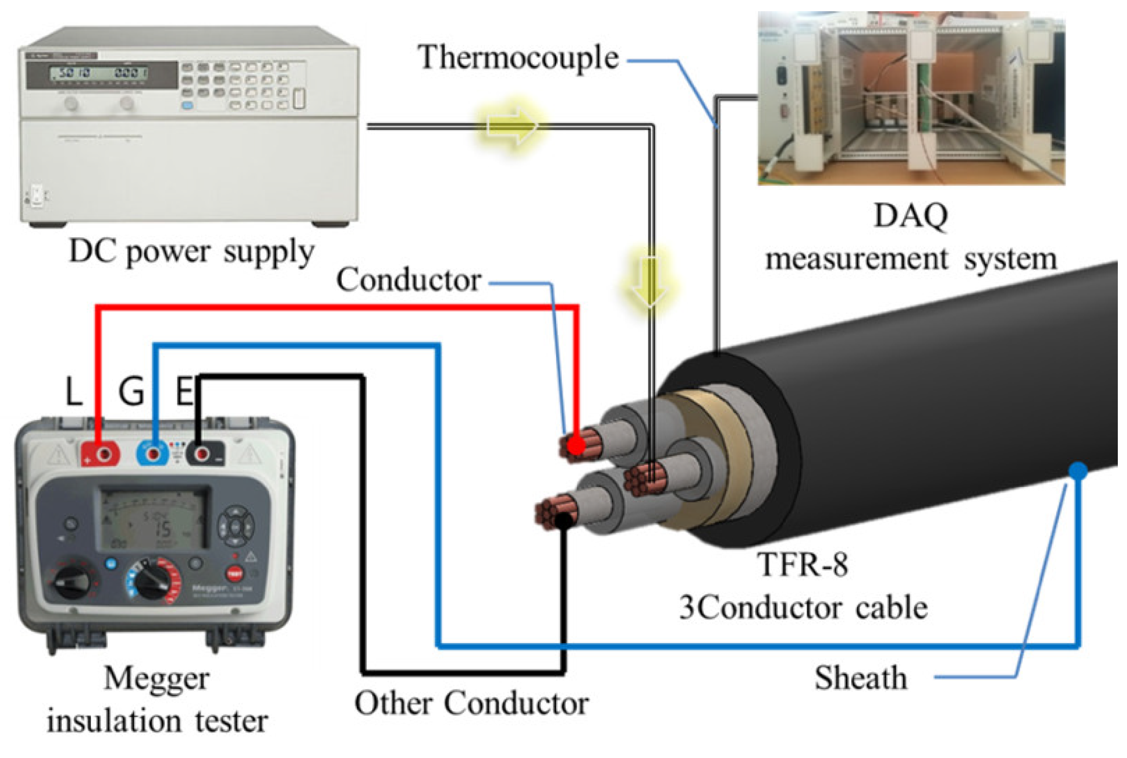
3. Experimental Methods and Results

3.1. Characteristics of Cable Insulation Resistance through Contact with an External Flame

The standard test method for flame-resistant power cables under fire conditions follows the IEC 60331 [14]. The IEC 60331 test method measures changes in insulation resistance using an insulation resistance tester by exposing cables for 90 min to a 750 °C flame. It verifies whether the insulation resistance is recovered to the original state after removing the flame for 15 min. The present study employed a Bunsen burner that used liquid petroleum gas as a fuel to measure a changes in cable insulation resistance due to contact with an external flame, as shown in Figure 2. A regulator and flow meter were used to adjust the flame length. The flame length was 150 mm, and the cable sample length was 900 mm. TFR-8 cable and VCTF cable were used (voltage rating: 0.6/1 kV), as shown in Figure 3. The major specifications of the cables are presented in Table 1. The TFR-8 cable consisted of mica tape, poly vinyl chloride (PVC), cross-linked polyethylene (XLPE), and filer complexly, and the VCTF cable consisted of only one PVC insulator. A voltage of 3 kV was applied using an S1-1568 insulation resistance tester. The main specification of S1-1568 is a resistance range: 10 k to 35 TΩ at 15 kV, short circuit and charge current: 6 mA, accuracy: ±5%, memory capacity: 11 h logging at 5 s intervals. We employed a mean value after three measurements for the experimental results. Changes in insulation resistance according to flame contact were evaluated using the leakage current accordingly.
Figure 4a,b show the experimental results that evaluate the characteristics of insulation resistance during the external flame contact of TFR-8 and VCTF cables. As a leakage current did not flow into the TFR-8 cable at room temperature, the maximum value of the insulation resistance tester, which was 7.5 TΩ, was maintained. However, it was reduced to 8 GΩ at approximately 300 s after contact with the flame. After the flame was removed, the insulation resistance was recovered to the maximum value at room temperature, which was 7.5 TΩ. The insulation resistance began to decrease after approximately 150 s when the flame was contacted again, which took about half of that during the first flame contact. As described above, the time of reduction in the insulation resistance of the TFR-8 cable was decreased further whenever flame contact was conducted. Moreover, even when the insulation resistance was recovered after the flame contact, degradation occurred in the insulation state of the cable. In the case of the VCTF cable, the insulation resistance at room temperature was 0.175 TΩ, which was much lower than that of the TFR-8 cable. The insulation resistance of the cable according to the external flame contact decreased immediately, and the insulation resistance value was 0.15 MΩ, which did not maintain the insulation state. A dielectric breakdown occurred instead. Even after removing the flame, the insulation resistance was not recovered to the original state. This outcome was due to the VCTF cable not having fire resistance and heat resistance performance. Thus, the insulator was burned by the external flame, and the insulation performance was not maintained.

3.2. Characteristics of Insulation Resistance According to Cable Lifetime

In general, cable manufacturers set the cable lifetime to 30 years for the production of cables. However, few studies have been conducted on fire risks of cables 30 years or older in terms of engineering viewpoints, although these studies were partially conducted [13]. Thus, this study verified the fire risk by measuring the insulation resistance of the cable considering the use-by period of the cable. To test the insulation resistance characteristics according to cable lifetime, the Arrhenius equation that accelerates aging by time and temperature was used, as presented in Equation (6).
K 2 = K 1 · exp { E a K b · ( 1 T 2 1 T 1 ) }
where K 1 is the accelerated degradation time, K 2 is the equivalent life, K b is the Boltzmann constant, and E a is the activation energy, in which 1.0 eV [15], the activation energy of the PVC, was substituted. In addition, T 1 is the accelerated degradation temperature, which was 130 °C given the insulator material characteristics, and T 2 is the temperature generally used in cables, which was 40 °C, the highest safety temperature used in low-voltage distribution board. Table 2 presents the accelerated degradation times derived to manufacture cables with an equivalent life of 10, 20, 30, and 40 years, respectively. A convection dryer was used to maintain a certain temperature constantly, and cables of 10, 20, 30, and 40 years of use were manufactured by heating the TFR-8 and VCTF cables for the accelerated degradation time at a temperature of 130 °C. To verify the insulation resistance characteristics of the cable according to cable lifetime, the accelerated degradation temperature of the cable was increased from room temperature by 20 °C increments to measure the insulation resistance.
Figure 5a,b show the experimental results of the insulation resistance and leakage current characteristics according to increasing temperature. The TFR-8 cable maintained the maximum value of insulation resistance up to a temperature of 117 degrees Celsius. Afterward, the insulation resistance decreased suddenly, caused by the increasing temperature. In case of the VCTF cable, the insulation resistance is 185 GΩ at room temperature and the insulation resistance is decreased sharply from room temperature. In comparison to the TFR-8 cable, the insulation resistance is much smaller than the TFR-8 cable. Therefore, the temperature factor is appropriate for accelerated degradation testing of cables.
Figure 6a,b show the graphs of the experimental results of the insulation resistance characteristics according to the equivalent life of the TFR-8 and VCTF cables. The TFR-8 cable, the degradation of which was not accelerated, maintained the maximum value of insulation resistance up to a temperature of 140 °C, and it began to decrease at 160 °C. However, the accelerated degraded cable had a significantly lower reduction temperature of insulation resistance, and the cables that had 10, 20, and 30 years of equivalent life exhibited a reduction temperature of insulation resistance at 80 °C, 60 °C, and 40 °C, respectively. In particular, the cable that had 40 years of equivalent life showed that the insulation resistance value was approximately 5 TΩ from room temperature, which was then reduced to 1 TΩ or lower from 60 °C. As exhibited in the test results, the insulation resistance value of the degraded cables that were not accelerated was not reduced even at a temperature of 140 °C, but that of the accelerated degraded cable was significantly reduced at the same temperature. As described above, the accelerated degraded cables may induce a short circuit or ground faults because of the insulation degradation depending on the surrounding environment conditions, resulting in high risk of fire occurrence.
The VCTF cable also exhibited the same result as the TFR-8 cable: the accelerated degraded cable had a larger difference in insulation resistance value that than of the cables without accelerated degradation. In addition, the insulation resistance of the cables that had 30 and 40 years of equivalent life decreased below 0.1 GΩ from 60 °C. The value 0.1 GΩ is the minimum insulation resistance value that the insulator must maintain for insulation performance. Therefore, the above result proves that the VCTF cable did not maintain the insulation performance even at 70 °C or at a lower temperature, which is the allowable temperature of the cable when the cable is used for more than 30 years. As shown in the experimental results, the difference in insulation resistance due to heat between the VCTF and TFR-8 cables is that the TFR-8 cable has a heat-resistant layer (mica tape) which can prevent the thermal decomposition of the insulator due to heat.

3.3. Insulation Resistance of the Cable Due to Over-Current

Insulation degradation may occur because of electric factors. If the conductor inside the cable is heated because of over-current, the temperature of the cable rises. Although the insulation resistance characteristics of the cable were evaluated according to flame contact and the increase in external temperature rise, the conductor inside the cable acted as a heat source, thereby increasing the temperature of the insulator. Therefore, analyzing the changes in the insulation resistance characteristics of a cable due to external and internal heat sources is necessary.
Figure 7 shows the experimental configuration diagram of the insulation resistance characteristics of the cable according to over-current. As the insulation resistance tester used in the experiment is a device that measures insulation resistance by applying the DC 3 kV voltage, it cannot be used in the current conducting state. Therefore, when using a three-core cable, the DC power supply is connected to one of the cores to configure a closed circuit that can apply over-current. The current was increased from 30 A, which was the allowable current of the cable, up to the point in which the insulation resistance was reduced. The conductors in the other two cores were connected to measure the insulation resistance with the insulation resistance tester. In addition, the K-type thermocouple was used to measure the surface temperature of the cable, and a surface temperature was measured in real time using data acquisition.
Figure 8a,b show the experimental results of the insulation resistance characteristics of the TFR-8 and VCTF cables caused by the over-current (internal heat source) and the convective dryer (external heat source). In the case of the TFR-8 cable, a leakage current did not flow up to 80 A, so that the insulation resistance maintained the maximum value. Afterward, the insulation resistance was suddenly reduced at 85 A. The insulation resistance was maintained at 7.5 TΩ, which was the maximum value, up to 140 °C, when the temperature of the cable increased by the external heat source. Then, the insulation resistance was reduced to 1.73 TΩ at 160 °C. However, in the case of the internal heat source, the insulation resistance was reduced to 0.76 TΩ at 125 °C. In the case of the VCTF cable when the temperature was increased by radiant heat, the insulation resistance was 60 GΩ at 40 °C of the surface temperature. However, it was approximately 15 GΩ when the temperature increased by the over-current, which showed a large difference. For the experiments of over-current, heat caused by the conductor is transferred from the inside to the outside through conduction. For the convection heater experiment, heat in the cable sheath is transferred by radiation, which is transmitted to the inside through conduction. Here, a heat loss occurs due to the convection current; therefore, the temperature difference inside the insulator affects the insulation resistance. The above results indicate that when a temperature increases because of the over-current, heat is emitted from the inside, resulting in a more aggravate effect on the insulator. Figure 9 shows a photograph after the test at a temperature at which the cable sheath is damaged.

4. Conclusions

This study evaluated the insulation resistance characteristics of a cable at a transient state, such as flame contact, accelerated degradation, and over-current. The results were compared and analyzed with those using the Arrhenius equation. The insulation resistance of the cable was reduced as the temperature increased. It was reduced by half whenever the temperature increased by 10 °C. Insulation resistance was affected directly by internal and external factors as well. For the cables with reduced equivalent life through accelerated degradation, insulation resistance was significantly more reduced at the same temperature. That is, the performance of the insulator could differ depending on the environment where the insulators were used even if they were used for the same period. As the TFR-8 cable was equipped with fire-resistant and heat-resistant abilities, the reduction of its insulation resistance was smaller than that of the VCTF cable according to flame contact and temperature increase. However, the reduction ratio of the insulation resistance was the same according to the temperature increase. For cables without fire and heat-resistant capacities, the cable’s performance may not recover due to a single event of temperature rise or contact with a flame. Thus, it is necessary to use cables with fire and heat-resistant capacities for power supply cables to prevent electricity-related disasters. The results show that insulator resistance can decline rapidly depending on the environmental conditions where the cables are used. Accidents can be prevented by predicting the lifetime of an electrical cable through the continuous measurement of temperatures.

Author Contributions

Total article structure design and writing, J.-H.K. S.-D.K. performed the tests and data collection. Both authors handled the project as the corresponding authors. All authors have read and agreed to the published version of the manuscript.

Funding

This work was supported by the National Research Foundation of Korea (NRF) grant funded by the Korea government (Mist) (No.2016R1DA1B03934234).

Conflicts of Interest

The authors declare no conflict of interest.

References

  1. National Fire Data System in the National Fire Agency. Fire Statistics Data Tables; National Fire Data System in the National Fire Agency: Sejong, Korea, 2016. [Google Scholar]
  2. Kang, S.-D.; Kim, J.-H.; Kim, J.-H. A Study on the Insulation Resistance in Cable with Rising Temperature. J. Korean Inst. Illum. Electr. Install. Eng. 2018, 32, 72–77. [Google Scholar]
  3. Ghorbani, H.; Abbasi, A.; Jeroense, M.; Gustafsson, A.; Saltzer, M. Electrical characterization of extruded DC cable insulation—The challenge of scaling. IEEE Trans. Dielectr. Electr. Insul. 2017, 24, 1465–1475. [Google Scholar] [CrossRef]
  4. Motori, A.; Sandrolini, F.; Montanari, C.G. A contribution to the study of aging of XLPE insulated cable. IEEE Trans. Power Deliv. 1991, 6, 34–42. [Google Scholar] [CrossRef]
  5. Lee, J.B.; Jung, Y.H. An amendment of the VLF tanδ criteria to improve the diagnostic accuracy of the XLPE-insulated power cables. Trans. Korean Inst. Electr. Eng. 2010, 59, 1644–1651. [Google Scholar]
  6. Nam, Y.H.; Choi, K.H.; Park, M.G. Power cable maintenance using cable cure based on isothermal relaxation current measurement. J. Korean Soc. Urban Railw. 2016, 4, 465–470. [Google Scholar]
  7. Liu, Y.; Cao, X. Insulation performance evaluation of HV AC/DC XLPE cables by 0.1 Hz tan δ test on circumferentially peeled samples. IEEE Trans. Dielectr. Electr. Insul. 2017, 24, 3941–3950. [Google Scholar] [CrossRef]
  8. Polanský, R.; Polanska, M. Testing of the fire-proof functionality of cable insulation under fire conditions via insulation resistance measurements. Eng. Fail. Anal. 2015, 57, 334–349. [Google Scholar] [CrossRef]
  9. Wang, J.; Shu, Z.-J.; Chen, Z. The protective effect of a fire-retardant coating on the insulation failure of PVC cable. Eng. Fail. Anal. 2013, 34, 1–9. [Google Scholar] [CrossRef] [Green Version]
  10. Polanska, M.; Prosr, P.; Polanský, R. Changes of insulation resistance of fire resistant cable under fire conditions. In Proceedings of the 2015 IEEE Conference on Electrical Insulation and Dielectric Phenomena (CEIDP), Ann Arbor, MI, USA, 18–21 October 2015; pp. 278–281. [Google Scholar]
  11. Um, K.H. Design of measuring system for insulation resistance and humidity in high-power XLPE cables operation and the relationship between insulation resistance and humidity in the oversheath. J. Inst. Internet Broadcast. Commun. 2016, 16, 179–184. [Google Scholar] [CrossRef]
  12. Guastavino, F.; Coletti, G.; Ratto, A.; Torello, E.; Michelato, P.; Celentano, M.; Zucchelli, A. An experimental study about the fire resistance of low voltage cables. In Proceedings of the Conference Record of the 2006 IEEE International Symposium on Electrical Insulation, Toronto, ON, Canada, 11–14 June 2006; pp. 174–177. [Google Scholar]
  13. Um, K.-H.; Lee, K.-W. A Study on Cable Lifetime Evaluation Based on Characteristic Analysis of Insulation Resistance by Acceleration Factor of the Arrhenius Equation. J. Inst. Internet Broadcast. Commun. 2014, 14, 231–236. [Google Scholar] [CrossRef]
  14. IEC 60331-1. Tests for Electric Cables under Fire Condition—Circuit Integrity; IEC: Geneva, Switzerland, 2018. [Google Scholar]
  15. Poirier, M.; Stonkus, D.; Benson, S. Condition monitoring of nuclear cables using the indenter modulus. In Proceedings of the 17th Annual Conference, Canadian Nuclear Society, Fredericton, NB, Canada, 9–12 June 1996; pp. 1–13. [Google Scholar]
Figure 1. Comparison of the insulation resistance between the experimental result and the Arrhenius equation according to a temperature. (a) TFR-8 cable (b) VCTF cable.
Energies 13 03611 g001
Figure 2. Experimental setup.
Energies 13 03611 g002
Figure 3. Configuration of the cable sample.
Energies 13 03611 g003
Figure 4. Insulation resistance of cables with flame contact. (a) TFR-8 cable (b) VCTF cable.
Energies 13 03611 g004
Figure 5. Insulation resistance and leakage current characteristics according to temperature ramp test of the cables. (a) TFR-8 cable, (b) VCTF cable.
Energies 13 03611 g005
Figure 6. Insulation resistance characteristics according to temperature of the accelerated deteriorated cables. (a) TFR-8 cable, (b) VCTF cable.
Energies 13 03611 g006
Figure 7. Experimental setup under the over-current condition.
Energies 13 03611 g007
Figure 8. Insulation resistance characteristics of the cables by the over-current and convection heater. (a) TFR-8 cable, (b) VCTF cable.
Energies 13 03611 g008
Figure 9. Photographs of the TFR-8 and VCTF cables after the over-current test.
Energies 13 03611 g009
Table 1. Specification of the test samples.
Nominal Sectional Area (mm2)Conductor Thickness (mm)InsulatorOuter Diameter (mm)Allowable Current (A)Allowable Temperature (°C)
TFR-8 cable2.52.1PVC, XLPE, Mica tape, Filer1430830
VCTF cable2.52.1PVC11.43070
Table 2. Accelerated degradation times of the cable calculated by the Arrhenius equation.
K 2 :   Equivalent   life   time 10 years20 years30 years40 years
K 1 : Accelerated degradation time22 h44 h67 h89 h

