1. Introduction
The consequences of a short circuit occurring near a synchronous generator depend on the starting moment of the short circuit (SC) and the state of excitation and operation before the fault occurs. In such cases, the transient direct current (DC) component of the fault current may exceed the alternating current (AC) component, and/or the sub-transient AC component may decay faster than the DC component, resulting in the SC current not crossing zero for several cycles [
1,
2].
The motivation for this paper derived from a concrete problem that occurred during a specific case, as well as consideration of the advantages and disadvantages of circuit breakers (CBs) with rapid reaction (with SF6 gas in some cases). Many studies have been carried out on this phenomenon. Some research dealing with a similar phenomenon that occurred in the energy system of the Republic of Kosovo (Kosovo is located in the center of the Balkans) has been provided in the references of this paper [
1,
2,
3,
4,
5].
A mis-synchronization event of a generator on the network is one of the worst types of fault for a synchronous generator; it has negative effects both on the generator itself and on the elements of the equipment that are connected to the generator [
1,
3].
The intensity and severity of the consequences of activating a non-synchronized generator on a network depend on a large number of influencing parameters.
The most dominant influence is the value of the phase angle δ between the generator’s rotor and the magnetic axes of the individual phases of the stator at the moment of inclusion.
This phase angle determines the value of the fault current that contains a DC component. The generator and the network elements must be protected against the high current that occurs during such an incident, so the circuit breakers (CBs) in the network must interrupt the total fault current as quickly as possible.
The non-zero-crossing of the current can be attributed to an asymmetrical current containing a DC offset. As a result, the circuit breaker has to wait for the current to reach the zero-crossing point for an interruption to take place. This will delay the total clearing time until the current’s zero-crossing is achieved. This non-zero-crossing phenomenon can delay the clearing process and can expose generating units to more stress by prolonging the duration of high current flow.
Further, this paper analyzes the effects of a mis-synchronized generator on a network that does not fulfill the necessary synchronization conditions. Special attention is given to the possibility of using a high-voltage (HV) CB to disconnect the failure currents [
2,
3].
An analysis was made on the power network model prepared with real data of the power network elements integrated into the electromagnetic transients program (EMTP), ATP. It is a universal software program system for digital simulation of transient phenomena of electromagnetic as well as electromechanical nature (EMTP-ATP). The simulation results were compared with real-time measured data obtained from the described real event.
The obtained results for different input parameters show a significant presence of the DC component of the current, which caused delays in the current crossing zero. As a consequence, the CBs could not disconnect the failure current beyond the time for which they were designed.
Appropriate measures are proposed to prevent such situations in case of an accidental non-synchronized activating of the generator on the network [
1,
2]. Therefore, various electrical relay protection systems for this kind of phenomenon have been developed to protect equipment in this mode of operation. The existence of any differences during the process of activating the generator on the network causes instant or cumulative damage to the turbine, generator, or other elements of the network [
3,
4].
Thus, the absence of these differences in the frequency, magnitude, and angle voltage phase is the basic condition that has to be met before activating the generator on the network [
5]. When these requirements are achieved, the generator is synchronized and ready for connection to the network.
The CB must be dimensioned so that it can switch off all symmetric and asymmetric fault currents. In addition, consideration must be given to the possibility of presence of a DC component of the fault current, which plays a very important role in determining the rated values of the CB [
1].
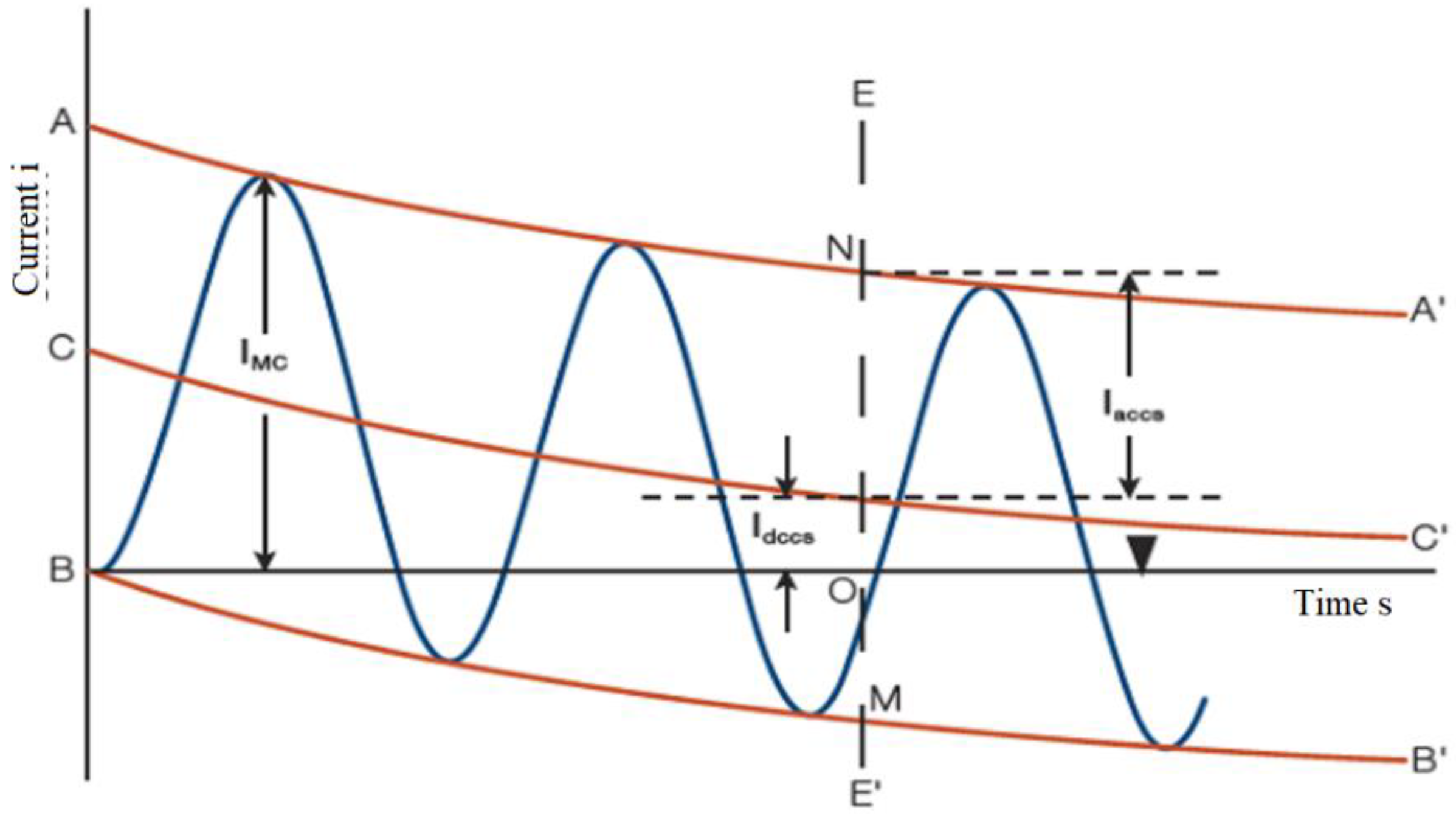
The following is a mathematical model that describes the asymmetry of the SC current due to the presence of a DC component, which makes it impossible to interrupt the fault current.
Based on
Figure 1, which represents the alternating component and degree of asymmetry upon separation, in reference to the standard IEC/IEEE 62271-100 [
6], I
dc, and I
ac can be calculated according to Equation (1):
In Equation (1) AA’ and BB’ are envelopes of a current wave; CC’ is the shift of the zero lines of the current wave at any time; EE’ is the moment of disjunction of contacts (the moment of ignition of the electric arc); I
MC is the shock current of SC; I
ac is the peak value of the AC component at the time of EE’; I
dc is the DC component of the current at EE’; ON is the sum of I
ac and I
dc at the instant of contact separation; OM is the value of the envelope of the current-wave at the instant of contact separation; and MN is the sum of the envelope of the current-wave ON and OM at the instant of contact separation. The SC current is characterized by two values [
6,
7,
8,
9]:
The root means square (rms) value of the AC, known as Isc.
The time constant τ of the DC component of the SC current.
From the example depicted in
Figure 1,
is the rms value of the AC of current, I
sc the instant of contact,
is the rms value of the DC of the current, and
is the degree of asymmetry at the instant the contacts separate; see Equation (2):
The DC component time function I
ac (t) is characterized by the sub-transient, transient, and steady-state currents during the sub-transient and transient time periods. These time periods are defined by the direct-axis sub-transient and transient time constants T˝
d and T’
d; refer to Equation (3):
The initial sub-transient and transient values of the three-phase short-circuit currents, I˝
kd and I´
kd, can be evaluated using the active voltages behind the respective impedance by applying Equations (4) and (5) (I
kd = I
k, which is the steady-state short-circuit current, the value of which should generally be obtained from the manufacturer).
The active voltages E˝
q0 and E´
q0 depend upon the preloaded current and can be evaluated using Equations (6) and (7):
The DC component i
dc (t) can be evaluated from Equation (8):
The peak value of the short-circuit current occurs between time t = 0 and t = T/2 of the short-circuit condition. The exact time depends on the preload conditions, the generator impedance, and the time constants. However, it is acceptable to calculate i
p at time T/2, i.e., at the first half-cycle of the short-circuit condition, using Equation (9):
The breaker should be capable of breaking any short-circuit current up to its rated short-circuit breaking current containing any AC component up to its rated value and, likewise, any percentage DC component up to the specified rating [
9].
The DC component value as a percentage (dc%) at the moment of CB contact separation can be calculated according to Equation (10):
where T
op presents the time of CB contact opening, which is provided by the manufacturer; T
r is the time needed for the protection relay to operate, and τ is the decay time constant of the DC component.
For the CB with a rated SC breaking current I
k, the DC component I
dck at the instant of contact separation (T
op + T
r) can be calculated according to Equation (11):
Thus, the DC component that the CB is capable of breaking during the test is determined according to the decay time constant τk on the premise that the maximum DC component equals the peak AC component at 0 s.
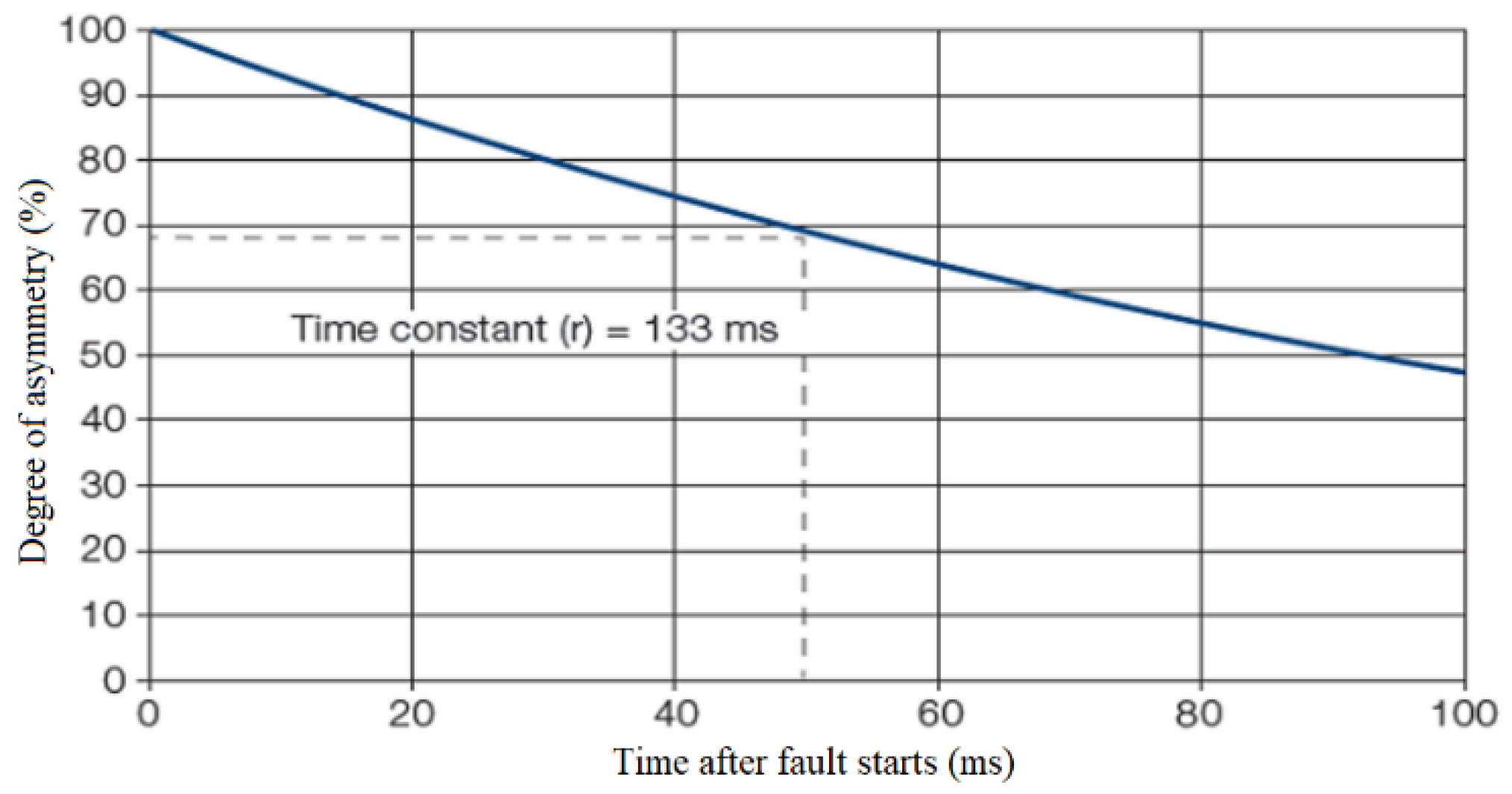
The standard IEC/IEEE 62271-37-013 defines a 133 ms time constant (
Figure 2) for the DC component of the rated system–source SC current. Referring to
Figure 2, the 133 ms constant corresponds to roughly 68% of the value of the asymmetry at the moment when the contacts are separated, e.g., at 50 ms [
6].
The time constant τ can be calculated according to Equation (12):
where X is the equivalent reactance of the system for the medium voltage (MV) side of the transformer, R is the equivalent resistance for the same point, ϖ equals 2πf (with system frequency f), and τ remains the instant at which the CB contacts separate [
6,
7,
8].
The scientific novelty of the paper is a thorough analysis of the case: the connection of the non-synchronized network generator to the energy system. Although this phenomenon occurs rarely under normal operating conditions, it can be caused due to failure in CB control systems.
A real case of SC current asymmetry due to the presence of a DC component has taken place in the energy system of Kosovo. Causes and consequences of such a phenomenon and the appropriate analysis is given in following sections.
2. Materials and Methods
The energy system of the Republic of Kosovo is connected to international transmission lines with the neighboring countries of Albania, Montenegro, North Macedonia, and Serbia, using high voltage transmission lines with high transmission capacities of 400 kV, 220 kV, and 110 kV. This solid connection of the transmission network with the surrounding networks makes the energy system of Kosovo one of the most important electrical nodes in the region [
4]. In the transmission system, various power CBs were installed by different manufacturers. In terms of the type of dielectric arc extinguishing medium, CBs with SF6 gas are the most common.
The protection relays are distant relays (Siemens (7SA612)) along with an over-current relay (7SJ612). These relays are installed in the generator field in substation 400/220 kV near the thermal power plant (TPP), “Kosovo B”. The protection devices used in this case are numerical relays to protect the short line that connects the generator to the transmission network [
10,
11,
12,
13,
14].
During the case under consideration, real-time measurements of the current and voltage were made and recorded on the SIEMENS digital relays at the moment when the generator was connected to the network. Measurements of the DC component were also made when the CBs were switched off.
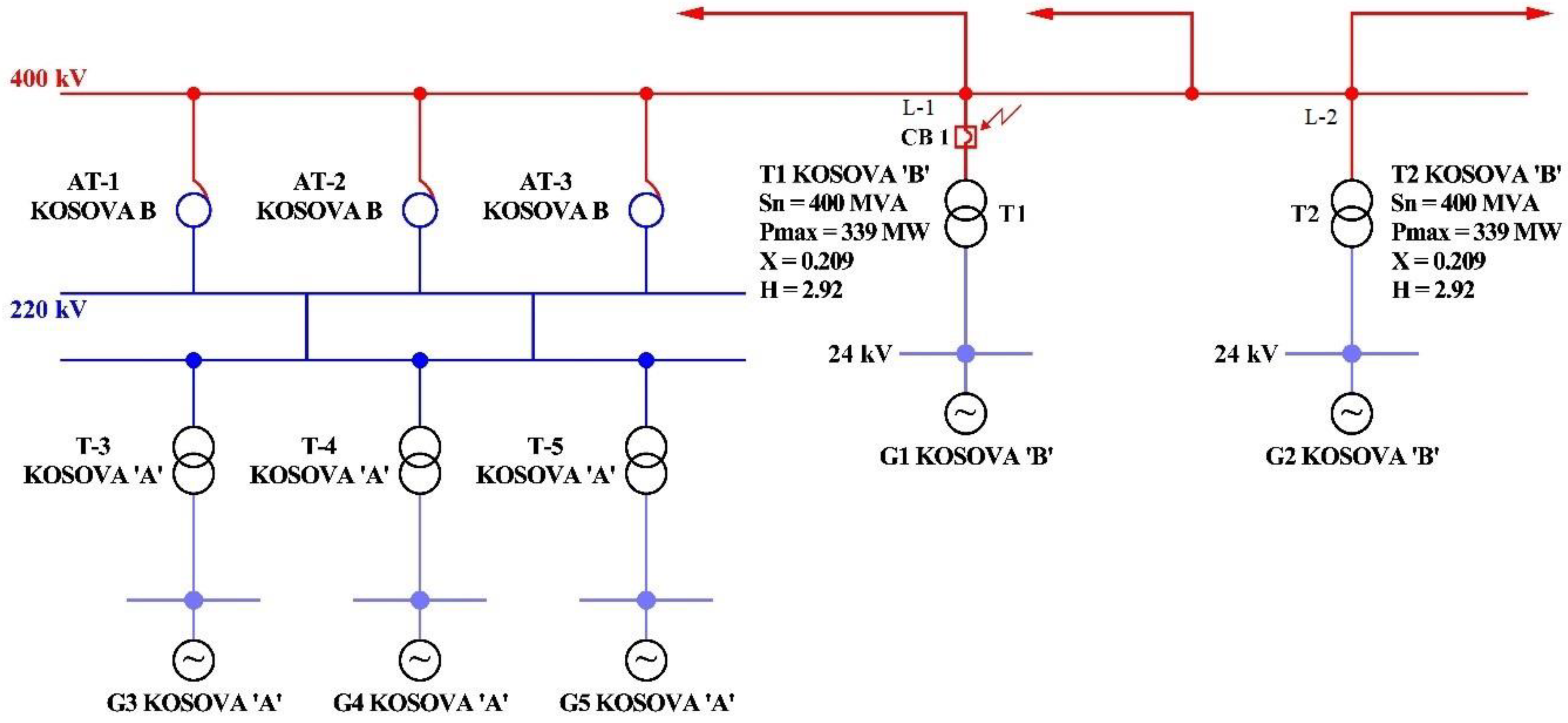
Figure 3 provides a simplified single line diagram where the main units of the generator in the TPP “Kosovo A and B” are connected. The critical circuit breaker (CB1) is also shown for when the observed event occurred [
13,
14].
Table 1 shows the data for generator units in TPP Kosovo A and Kosovo B.
Table 2 shows the data for transformer in TPP Kosovo A and Kosovo B.
Table 3 shows the data for the transmission line from 400 kV substation to the generator where the study was planned.
The following power network model that describes the asymmetry of the short-circuit current due to the presence of the DC component, which is the cause of the impossibility of interrupting the fault current.
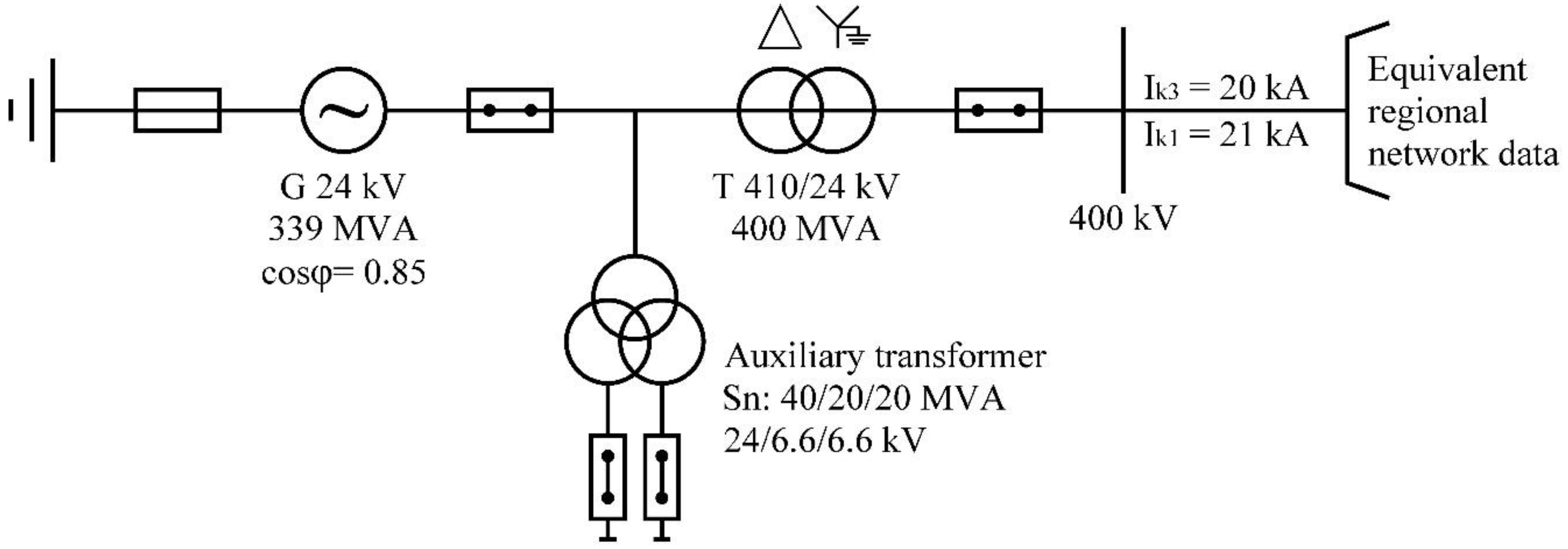
Simulation data for the equivalent network (SC power at 400 kV, I
k3 = 20 kA, I
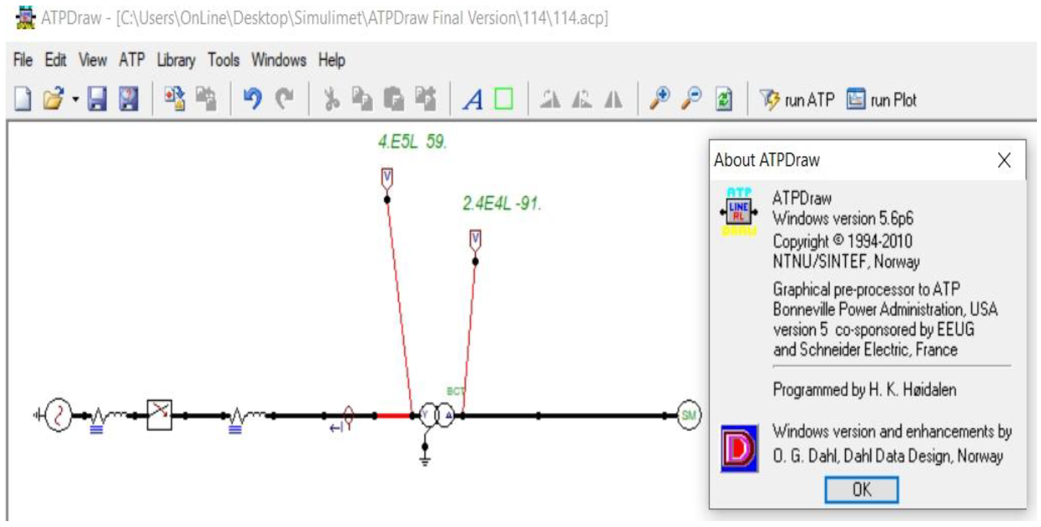
k1 = 21 kA) were taken from the simulation with PSS-E of the regional energy system of southeast Europe. In particular, simulation data were taken from short circuits in 400 kV bus-bars in the substation Kosovo B located in the energy system of Kosovo as shown in
Figure 4. A SC was simulated with PSS-E on the 400 kV bus-bars where the generator is connected.
Network data for simulating an equivalent network: S
k3 = 13,856 MVA, S
k1 = 14,549 MVA (I
k3 = 20 kA, I
k1 = 21 kA). SC impedance data in substation Kosovo B is Z
k = 2.61 + 17.97j Ω, whereas X/R = 6.88499. The X/R ratio is simply the ratio of the system reactance to the system resistance; the X/R ratio affects the level of SC current which CB is required to interrupt. Other simulation data include the generator data: U
n = 24 kV, S
n = 399 MVA, earthing resistor of generator r = 950 Ω, step-up transformer: S
nT = 400 MVA, uk% = 11%, 24/400 kV/kV, and auxiliary transformer: Sn = 40/20/20 MVA, 24 kV/6.6/6.6 kV [
14]. The SC data (in real time) was taken from transmission system operator (TSO).
The TSO uses PSS-E software for SC calculation. These data allow us to determine the equivalent network impedance that will be used for simulations with the EMTP-ATP software (
Figure 4).
The scheme that is used for simulation is presented in
Figure 4 [
14].
For the validation of the power network model, the comparative methodology of the data recorded during the real event is used, with the data obtained from the power network model constructed with real network data at the moment when the event occurred.
Case Study
The event under review occurred on the substation of TPP Kosovo B, where mis-synchronization of the generator with the energy system of Kosovo occurred.
To explore this phenomenon, an example featuring a situation of the random inclusion of a non-synchronized generator in Kosovo’s energy system with a CB of over 400 kV is analyzed in this paper.
This situation shows that there can be significant damage to the CB [
14]. The observed fault occurred in the command circuits of the generator CB, at a load of 1050 MW.
There may be damage to the control cables if the generator is switched off and then immediately switched on to the network without fulfilling the synchronization conditions [
14,
15,
16,
17].
Table 4 shows the values recorded during a time of 60 ms for I
rms (effective value of the current) depending on the time during the considered case [
14].
The case investigated occurred on 23 August 2011. This case was the result of accidental activation of the CB with SF6 gas without synchronizing the generator with the network due to some problems in the control circuits (failure in the generator CB control circuit). The DC component had a significant effect on the CBs and caused difficulties during the shutdown process. Switching off the current for less than 50 ms under high voltage, without the current passing through zero, can lead to damage of the CB, as CBs are not designed to break at such faults [
14].
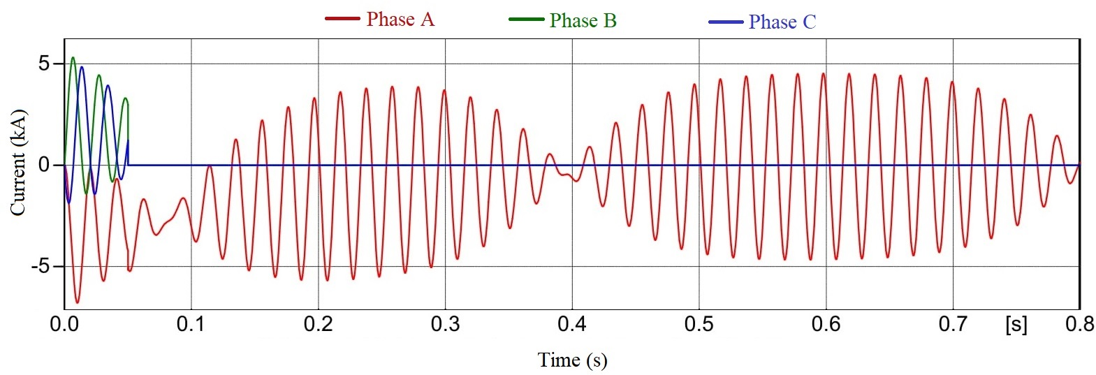
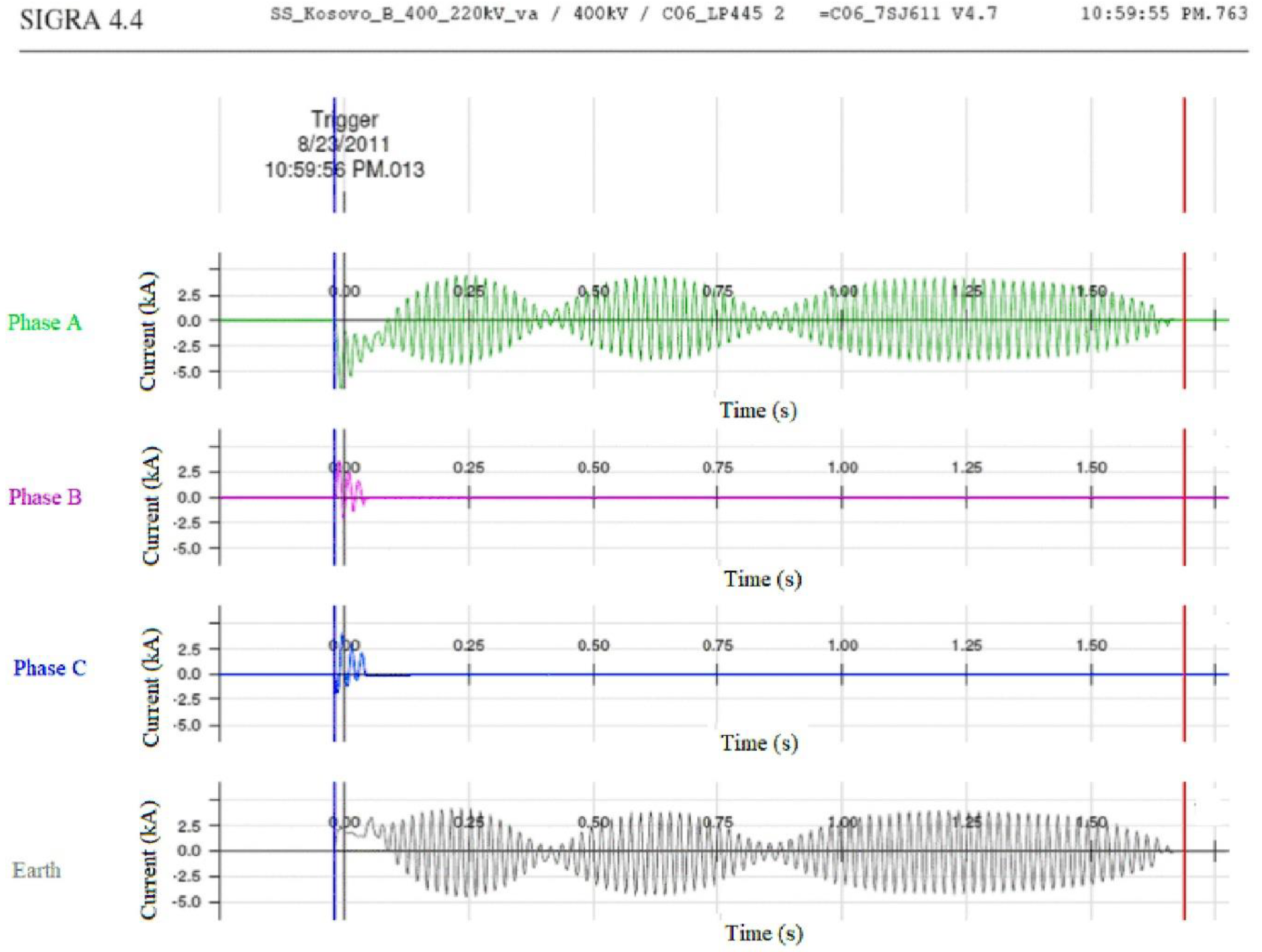
With the operation of the relay protection system, the 400 kV CB in the step-up transformer receives an exclusion order in such a case.
Phases B and C through the Ib and Ic current were interrupted at the zero crossing 3 cycles after the incident’s initiation. Unlike phase A, the trace Ia current cleared in 5–6 cycles due to its delay in reaching the zero crossing. This non-zero-crossing phenomenon can delay the clearing process and expose the generating unit to more stress by prolonging the duration of the high current flow.
Switching off and current interruption occur in two phases (B and C). In phase A, the current interruption is absent because the first passage of the current through zero occurs only after the end of the shutdown operation and the arc-extinguishing attempt (
Figure 5).
To explain the event, we performed simulations using a simplified simulation model, where the origin, development, and nature of the overall phenomenon are presented [
14].
The DC component and its quenching depend on the time constants of the circuit at the moment of failure. For example, its quenching depends on the R/L parameters that are generated for the resistance (R) and inductance (L) of the power lines, transformers, and generators in a transmission system.
The R/L ratios determine the proper DC component decay time constants of various elements, and the overall decay of the DC components when a fault occurs depends on the combined time constants of all fault sources [
14,
18,
19,
20]. The presence of a high DC component value ensures that the current in phase A does not pass through zero for approximately 100 ms (the DC component and its shutdown depend on the time constants of the circuit at the moment of failure, i.e., its shutdown depends on the generated parameters R/L).
From the recorded events of the relay shown in
Figure 5, it can be seen that the current in phases B and C was switched off successfully from the CB. The oscillogram occurrence of the event, according to the record of the relay protection system in the 400 kV step-up transformer, is shown in
Figure 5 [
14].
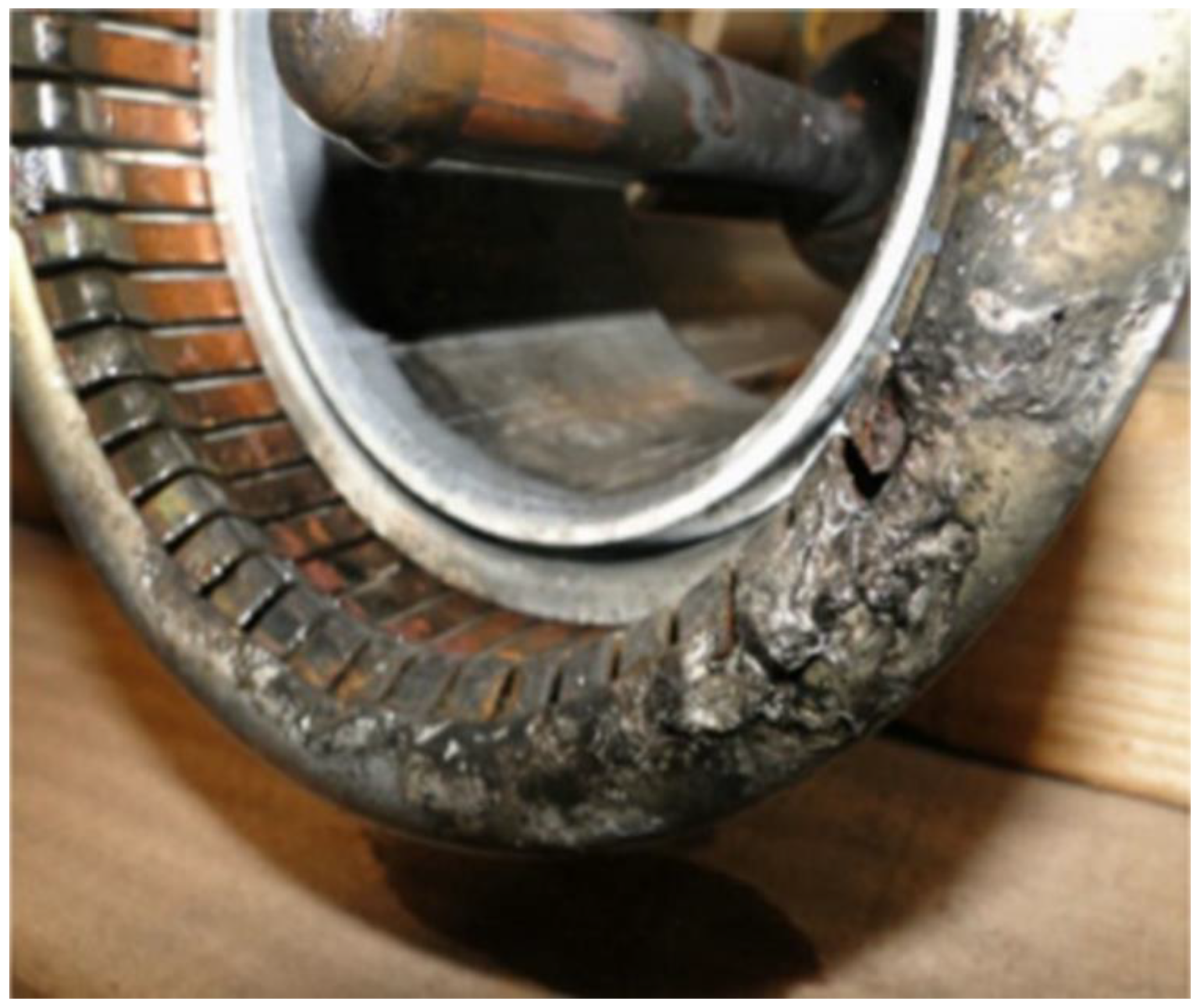
Due to the failure of this CB to turn off the electric arc, there was an explosion in the CB (
Figure 6), which caused great environmental damage to the neighboring elements of the substation [
14]. As a result of this fault and the explosion of the CB, the following damage occurred:
The generator was out of operation for 8 h.
There was damage to the main contacts in a single 400 kV CB chamber.
There was damage to three supporting isolators of the CB on adjacent transformer bays.
There was reduction of the safe operation of the substation due to using the last generator from the generator reserve.
Figure 6 shows the damage to the main contact in a single 400 kV CB chamber [
14].
The measured data show asymmetry, which was the cause of the DC component occurrence at each phase. In phase A (
Figure 5), the DC component is very large, which causes the AC component to move on the x-axis.
Therefore, due to the presence of high-value DC components, the current in phase A does not pass through zero in approximately 100 ms. The type of fault and the conditions in which it occurs determine the DC component value.
The activation of a non-synchronized generator on the network causes high-current failures, such as SC current failure. Transient electrical and mechanical processes are dependent on the angle of the rotor, causing considerable stress on the generator [
19,
20,
21,
22,
23]. The DC component of the fault current, which occurs at that moment, causes the appearance of highly asymmetrical currents between the phases, making it difficult to break the fault current and thus extinguish the electric arc [
5].
This leads to the appearance of high temperatures or even an explosion in the CB pole chambers. The state of the current as a result of accidental activation consists of two elements: periodic (AC component) and aperiodic (DC component). The aperiodic component has a high value and is particularly prominent in phase A [
14].
3. Results
A simulation power network model was developed in the EMTP-ATP and Power System Simulator for Engineering (PSS-E) software package to monitor the behavior of the generator during the activation of a non-synchronized generator on the energy system at different angles between the generator and the network. The model was developed and tested based on real-time events [
14,
18].
To simplify the model, an equivalent network was modeled with the generator.
To validate the power network model, a simulation was used for the same phase angle of 114° (angle of 114° has been taken from the SIEMENS digital relays data), under which the activation of a non-synchronized generator in the network occurred. The simulations of these cases are given in
Figure 7,
Figure 8,
Figure 9,
Figure 10,
Figure 11 and
Figure 12 [
14,
23,
24,
25].
The simulation of the critical angle of 114° (under which the non-synchronized generator is connected on the network) is based on the specific case that occurred, whereas the other angles (50°, 90°, and 0°) were taken randomly to reveal what happens in those cases (for analytical purposes only).
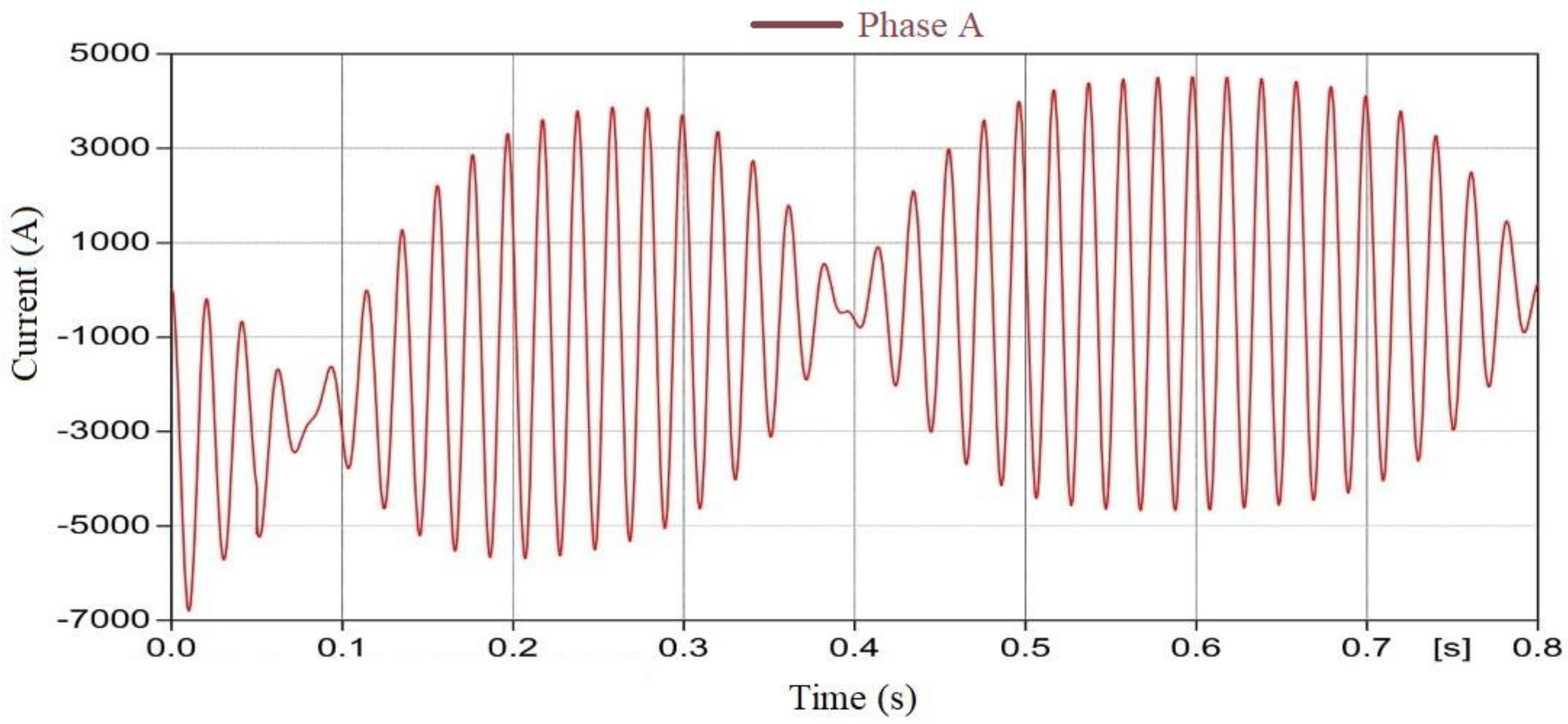
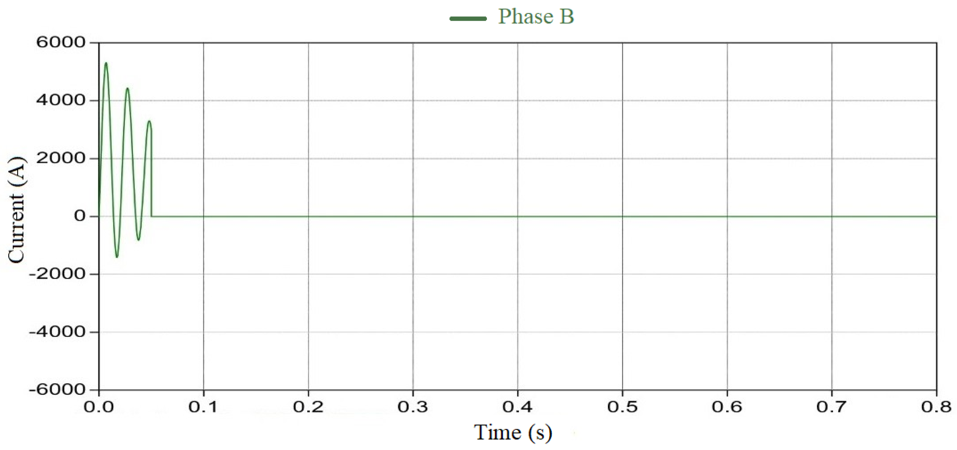
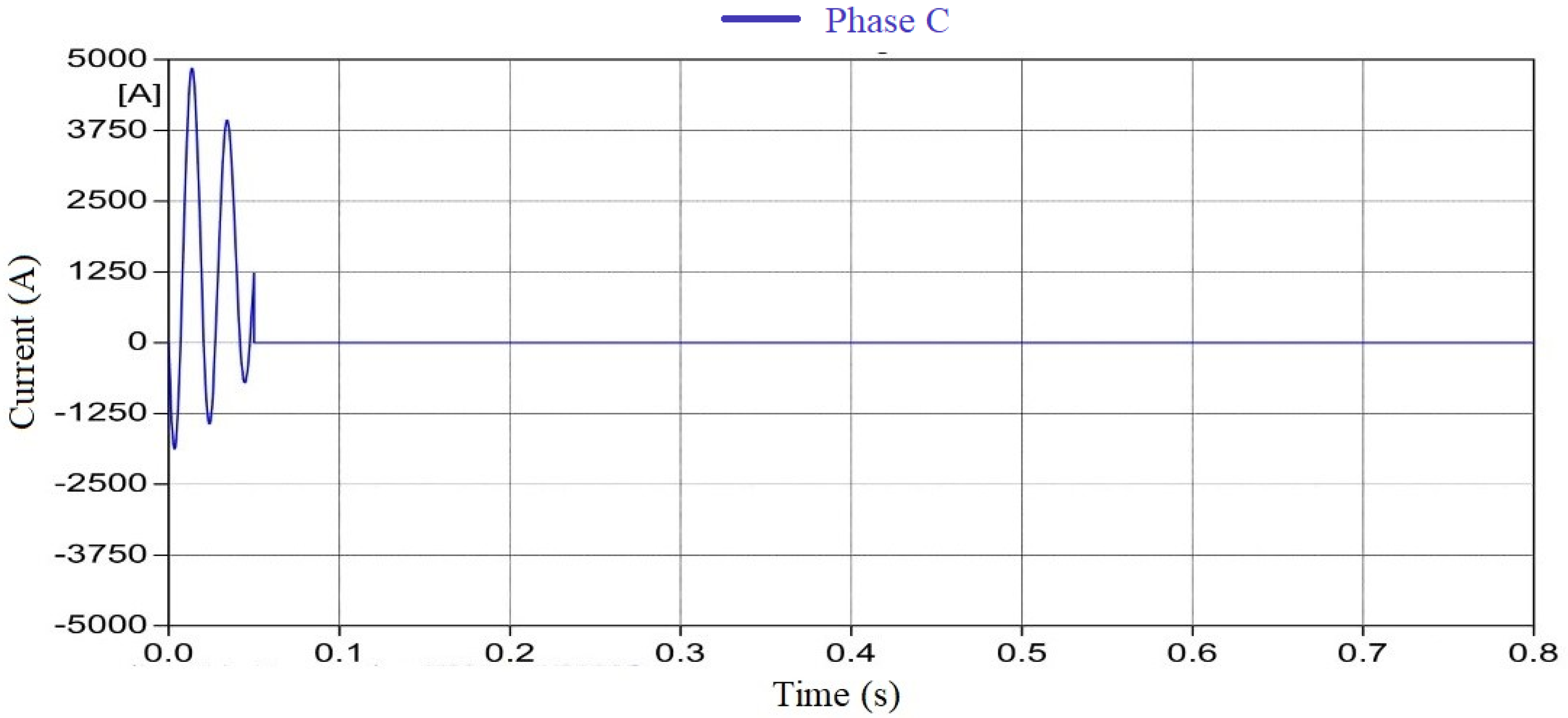
In
Figure 7,
Figure 8 and
Figure 9, simulations are provided that show the oscillations of the generator network during the activation of a non-synchronized generator at a 114° angle separated for each phase. At the time of the non-synchronized activation of the generator to a voltage level of 400 kV on the generator side, the angle was 59°; at that time the network had a phase shift of −55° [
14]. In this case, the difference between the angle of −55° and the angle of 59° was 114°.
Thus, the 400 kV CB was switched on between these two vectors:
−55° on the side of the strong network;
59° on the side of the generator, yielding an angle of 114° between the two sides of the CB.
The results of several simulations using the implemented model show a good correlation with the results recorded during the considered event in real-time.
By analyzing the curves shown in
Figure 7,
Figure 8 and
Figure 9, it can be seen that the oscillation duration is approximately the same as that in
Figure 5. The shape of the curve is the same as that of the DC component (very high in both cases, including the time constant).
The delay in passing the current through zero is caused mainly by the rapid movement of the rotor from the initial phase angle δ = 0. In this case, the constant of the inertia of the generator–turbine group has a decisive influence on this phenomenon.
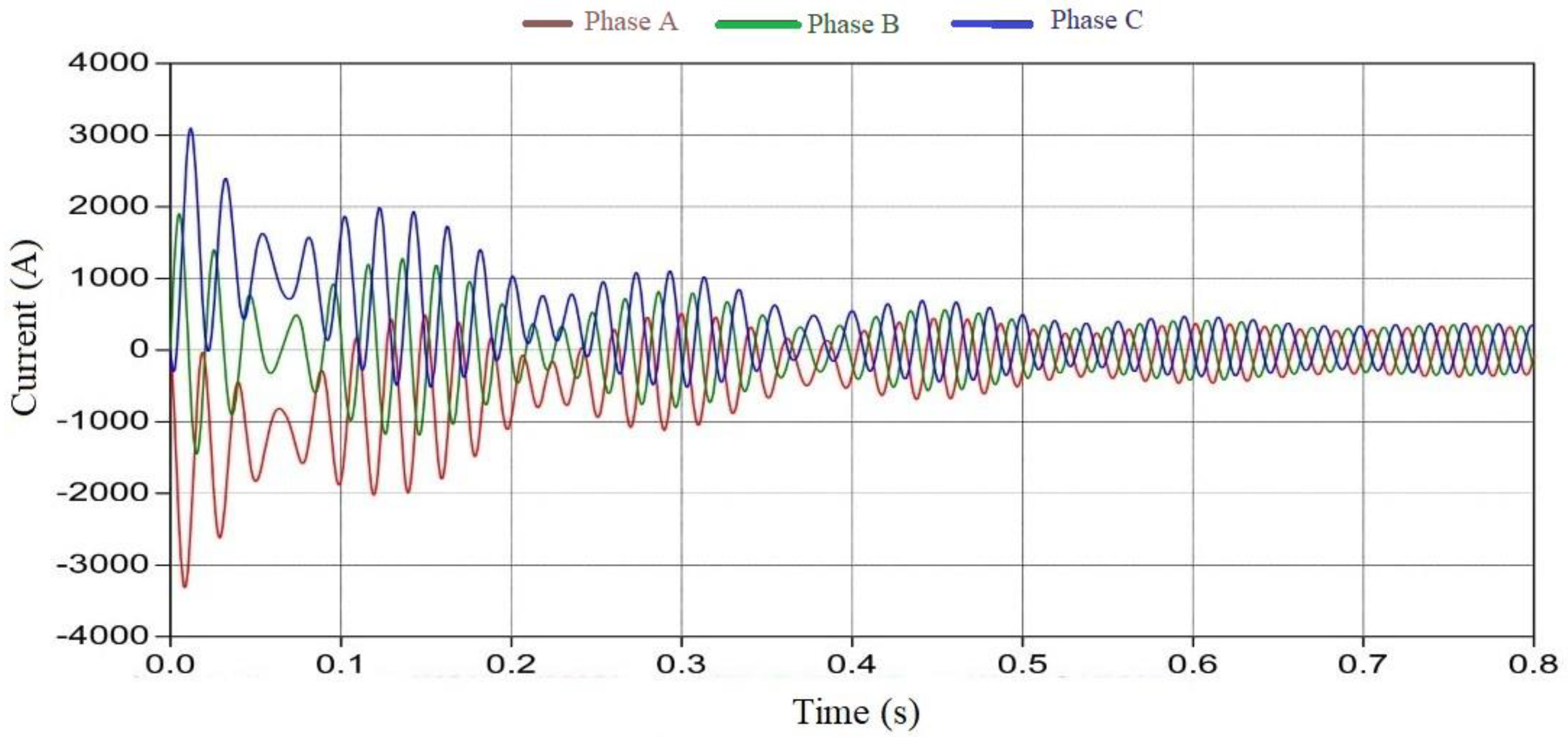
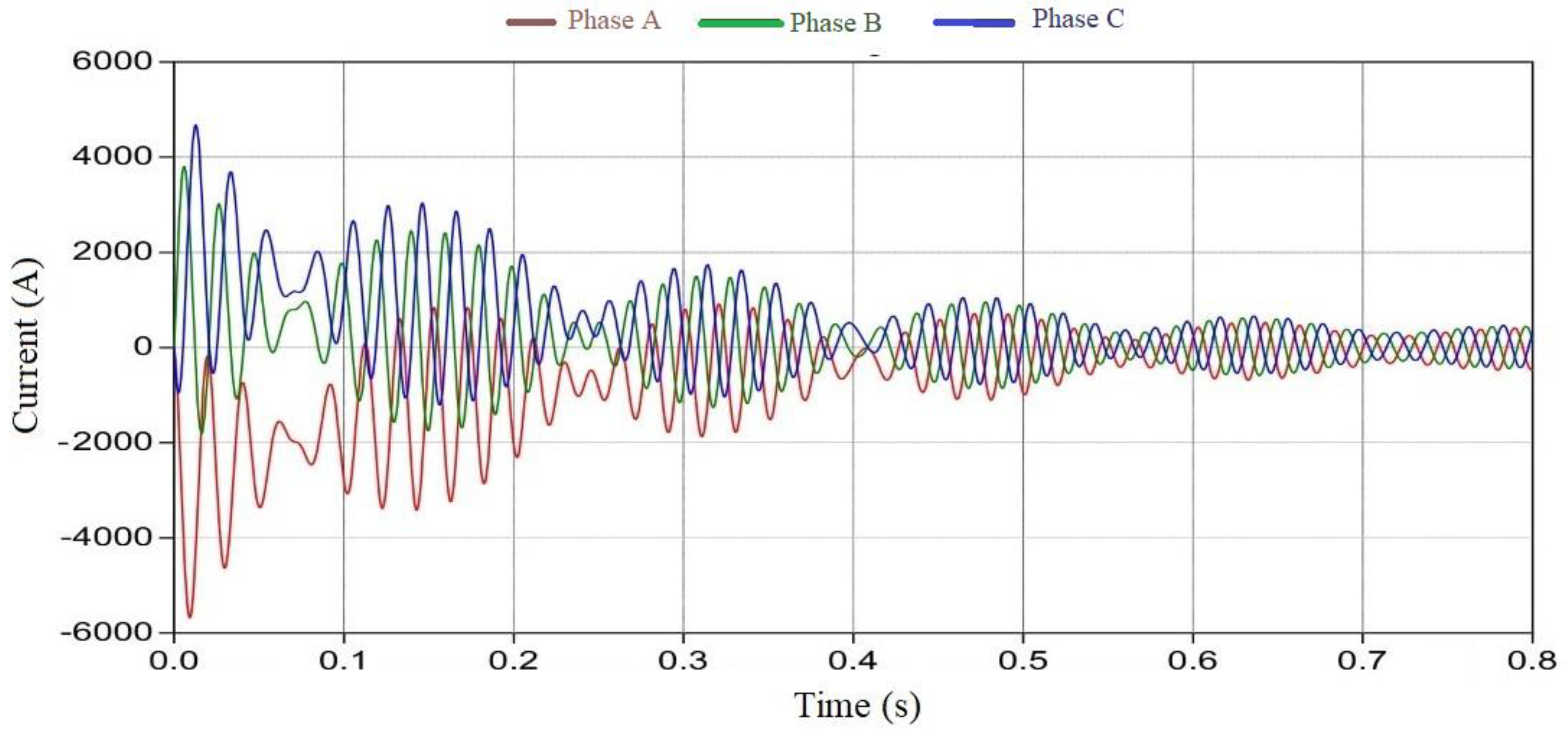
Notably, the current, due to the presence of a DC component, does not pass through zero (as seen in
Figure 5 and
Figure 7) for a long period of time, thus presenting a problem for the AC CB during the deactivation of this current, except where the angle is zero (
Figure 12) [
26,
27].
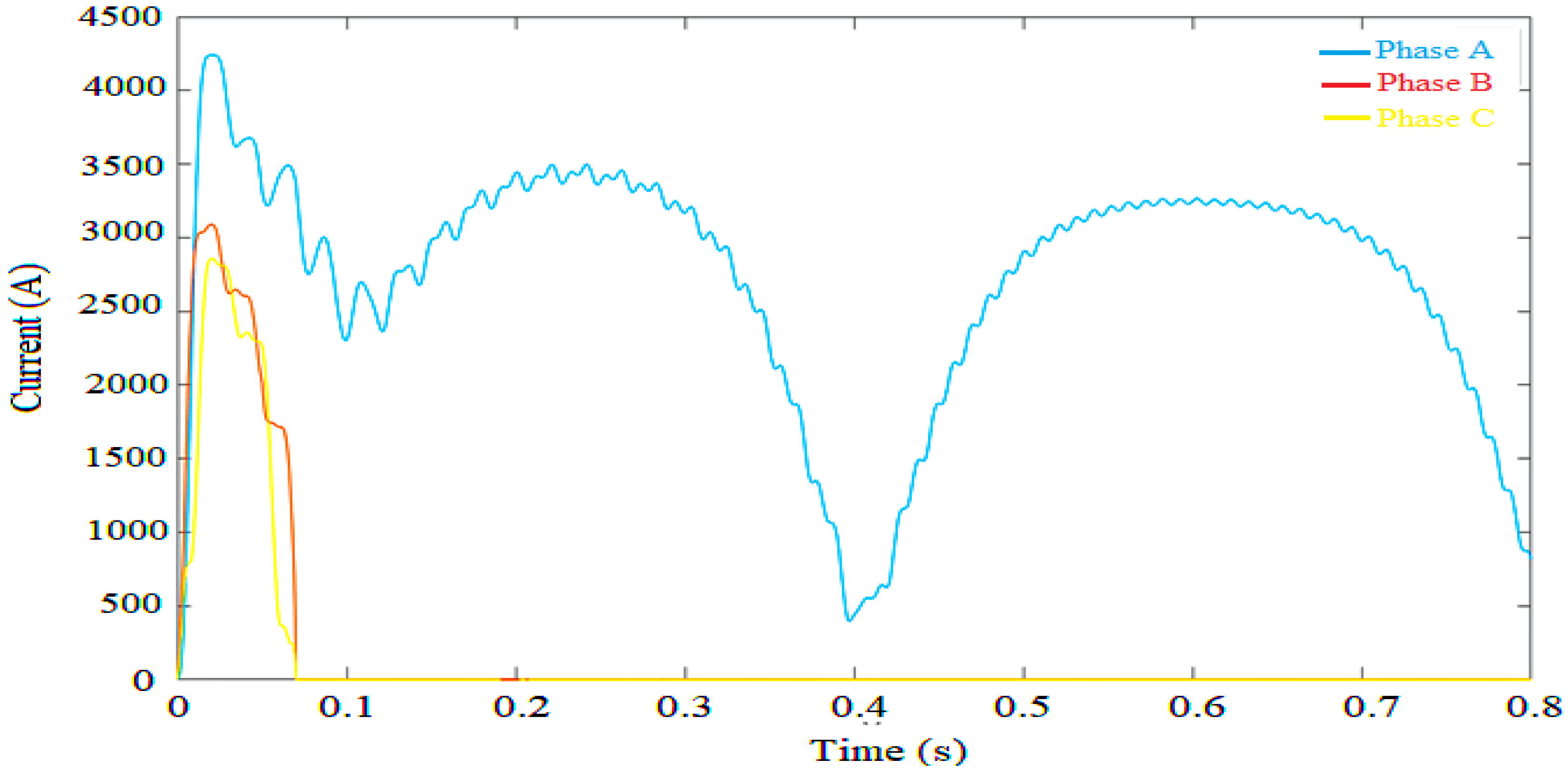
Table 5 shows the values determined by the EMTP-ATP. These values were extracted in MATLAB to calculate the I
rms (effective value of current) for an angle of 114°.
The times during the real events and simulations were synchronized concurrently to compare the obtained values. The results obtained with EMTP-ATP and the effective value of the current calculated with the MATLAB software (
Figure 13,
Table 5) are very close to the true recorded values (real-time events,
Table 4) [
2].
Table 6 gives the comparative error values in percent for the I
rms of the values obtained during the real event and the values obtained using a simulation with an equivalent model, as shown in
Figure 13. A single line diagram of the simulation network with EMTP-ATP is shown in
Figure 14.
4. Discussion
This paper presents an analysis of the phenomena that accompany the process of switching on a non-synchronized generator on a network from the perspective of the occurrence of current and voltage. Special attention has been given to the event that took place in the energy system of Kosovo on 23 August 2011—more specifically, in the TPP Kosovo B.
This phenomenon rarely occurs in practice but can also occur as a result of various faults in the CB control and command circuits. As a result of this activation, the consequences can vary, depending on how and when a non-synchronized activation took place. These oscillations are characteristic of the shape of the curve with the presence of a high DC component of the current, which affects the time delay of the alternating current component to pass through zero.
The scientific novelty of the work is its all-encompassing analysis of a specific case: the connection of a non-synchronized network generator to a power system. Although this situation rarely occurs under normal operating conditions, it can be caused due to a failure in circuit breaker control systems.
The consequences at the substation can be significant. Therefore, it is necessary to analyze the phenomena that occur in such a case to provide input data for the adequate selection of equipment.
In this paper, we analyzed the effects of the rapid shutdown of a generator from the system and the possibility of applying time delays for the operation of the CBs in these specific cases, which have an impact on the elimination of the DC components and the passage of the fault current through zero.
Thus, we presented the advantages and disadvantages of applying the time delay to disconnect the circuit breaker in these circumstances of device failure.
An additional contribution is our development of a model that provides results comparable to the real data recorded during the real event and can be used to analyze different cases for the selection of CBs in the energy system.
5. Conclusions
Recordings of behavior during this event show the presence of a DC component with a large value. This does not allow the SC current to pass through zero for several tens of ms, which resulted in serious damage to one pole of the CB.
This non-zero-crossing phenomenon can delay the clearing process and expose the generating units to more stress by prolonging the duration of high current flow.
A detailed analysis of the behavior of the generator on the network during various failures is very important to determine an appropriate CB to cover all the conditions that can occur in the system during various faults, to protect the elements of the power system.
High-voltage CBs with SF6 gas that are used for generators have special requirements compared to other CBs. In particular, they must be able to interrupt the fault currents that do not pass through zero in several cycles.
By comparing the time shapes of the SC currents in the case of non-synchronous switching, it can be seen that the currents have very high amplitudes, where the waveform of the current depends on the angle of the generator compared to the network.
In the case where the voltage angles of the generator and the network are zero, the direct current component rapidly declines, and all three-phase currents pass through zero, which allows for the rapid shutdown of the electric arc.
Other angles are different because, due to the presence of a direct current component of high-value currents in certain phases, the passage through zero is delayed. In our case, the time delay was 200 ms, which caused the electric arc in the CB, which could cause damage to the CB in some cases.
If the CB is installed to connect the power plant to the network, then a higher time constant should be used. Thus, a breaker with a higher permissible DC component percentage of the SC current or a CB with a higher braking power should be selected.
The consequences of adding this delay should be further analyzed in the context of their effects on other elements of the system, including transient stability.
The quick deactivation of relay protection by generator switches is not an advantage in all situations, which should also be taken into account. In the observed case, for example, a switch-off delay would have allowed the DC component to pass through zero, allowing the switch to deactivate this fault without any problems during the activation of a non-synchronized generator in the network.


