Enhanced Intelligent Energy Management System for a Renewable Energy-Based AC Microgrid


 ,
,  ,
,
Abstract
:
1. Introduction
- State machine control strategy
- Rule-based fuzzy logic strategy
- Classical proportional integral (PI) control strategy
- Frequency decoupling and fuzzy logic strategy
- Equivalent consumption minimization strategy (ECMS)
- The system and its devices: Instead of using batteries as storage means in the same way as other researchers, an SC is used to enable the system to follow fast-changing load demands while allowing the battery to respond at slower rates. SC is characterized by instantaneous power and much faster response times (charging/discharging) than those of batteries [24].
- Reliability improvement: As the battery is retained to respond to slow load/PV production changes through assigning the SC to the fast ones, the battery life span is increased [25].
- The proposed EEMS: Previous EMSs use a condition for each component, as well as for the control of the deficit and excess power. One of our achievements was to update these classical strategies by controlling the system elements using decision (or connection) variables. However, these variables may react to facilitate rapid reactions against any power fluctuation using decision making [26].
- Study of the global power: The developed work in this paper is compared to other related studies, where the overall power of the system is evaluated and discussed, covering aspects that were ignored in some research articles [27].
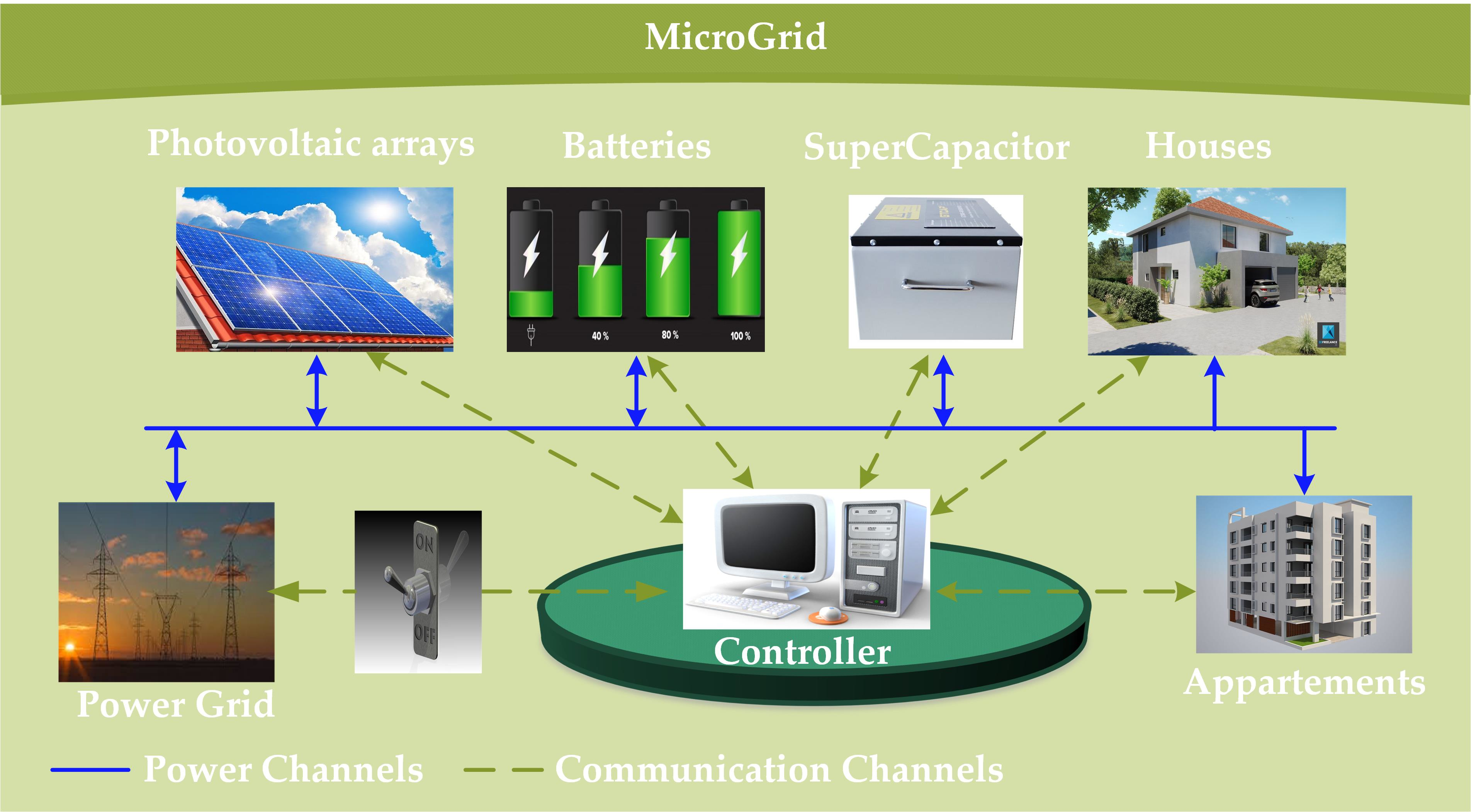
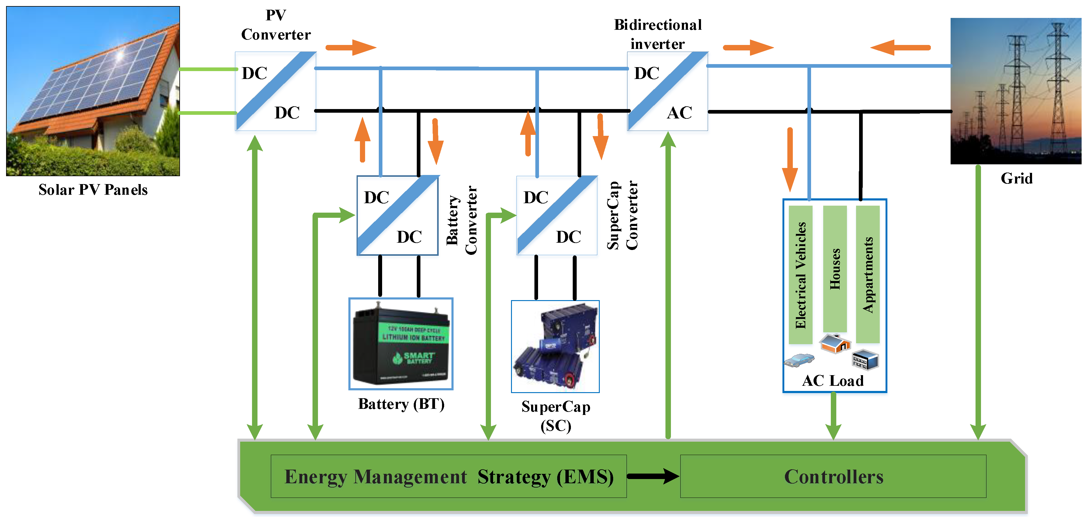
2. System Description and Methodology
- Solar PV panels.
- Lithium-ion batteries (BT), considered as a long-term power source.
- Super-capacitor (SC), considered as a short-term power source.
- Grid, which is resorted to during low solar irradiance and when the SC and BT are in discharged states.
- Enhanced energy management system: EEMS.
3. System Modeling
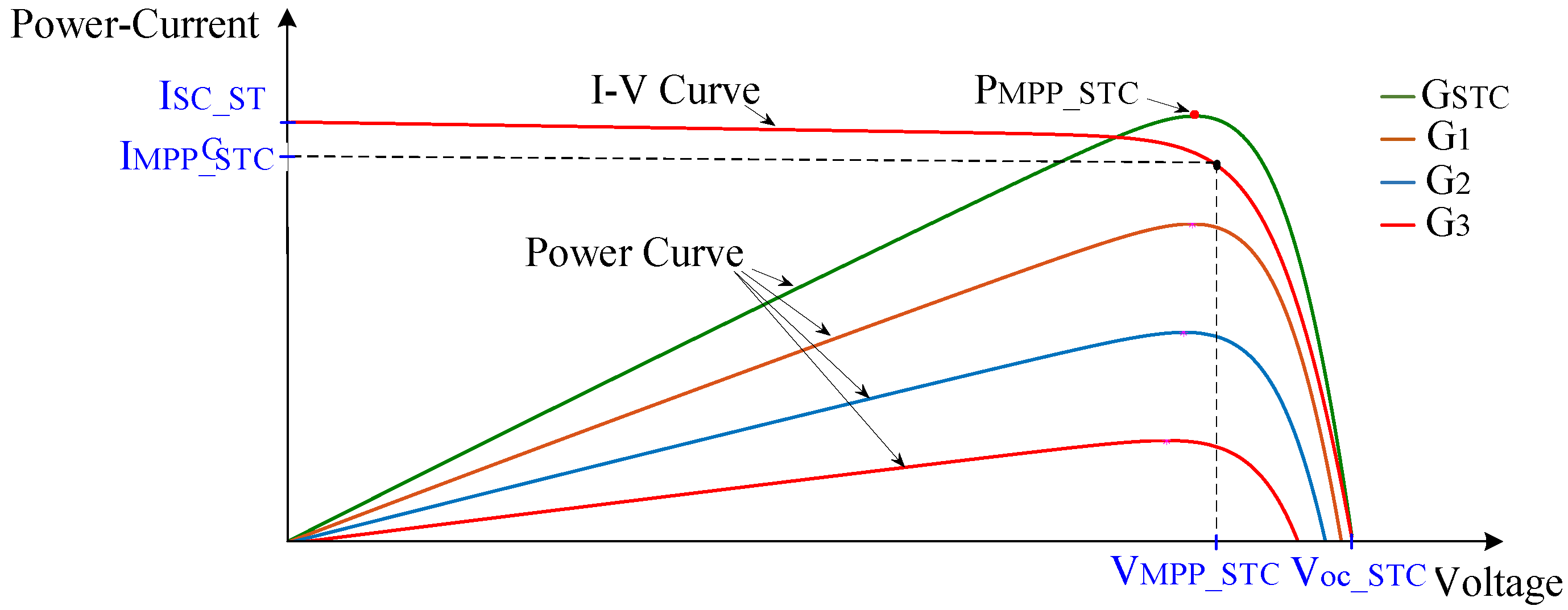
3.1. PV Model
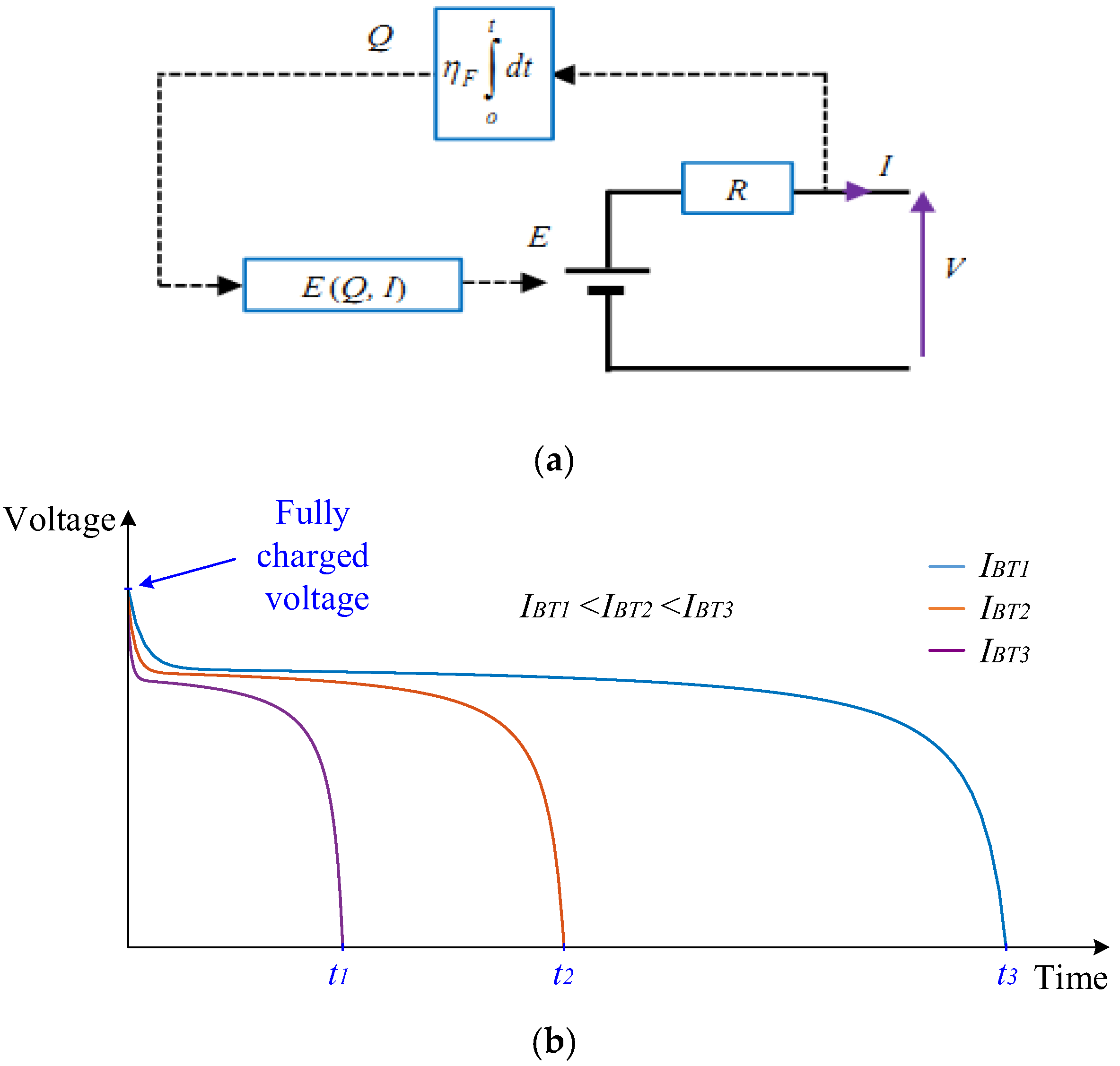
3.2. Battery Model
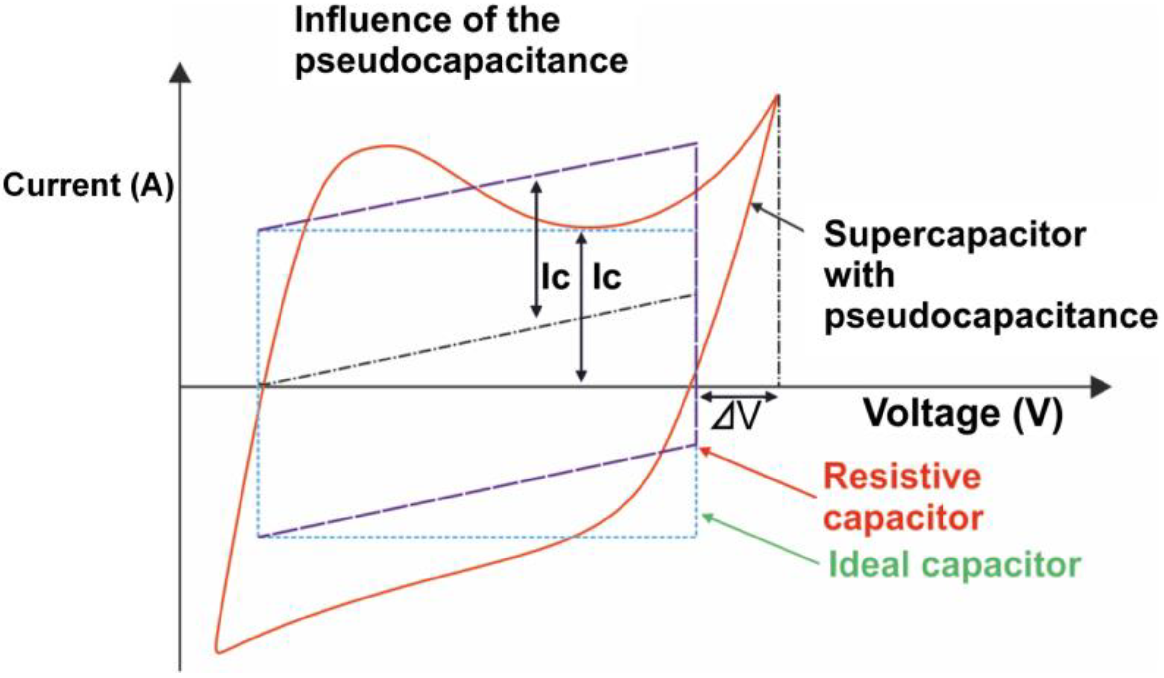
3.3. SuperCapacitor Model
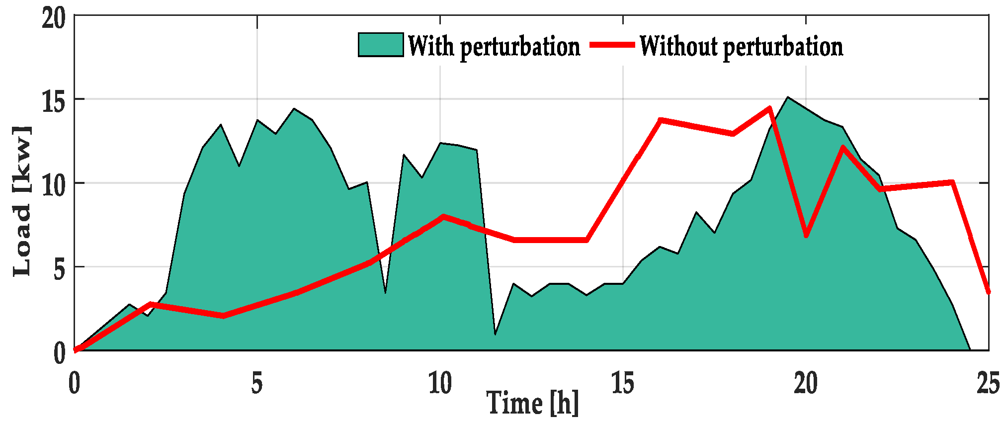
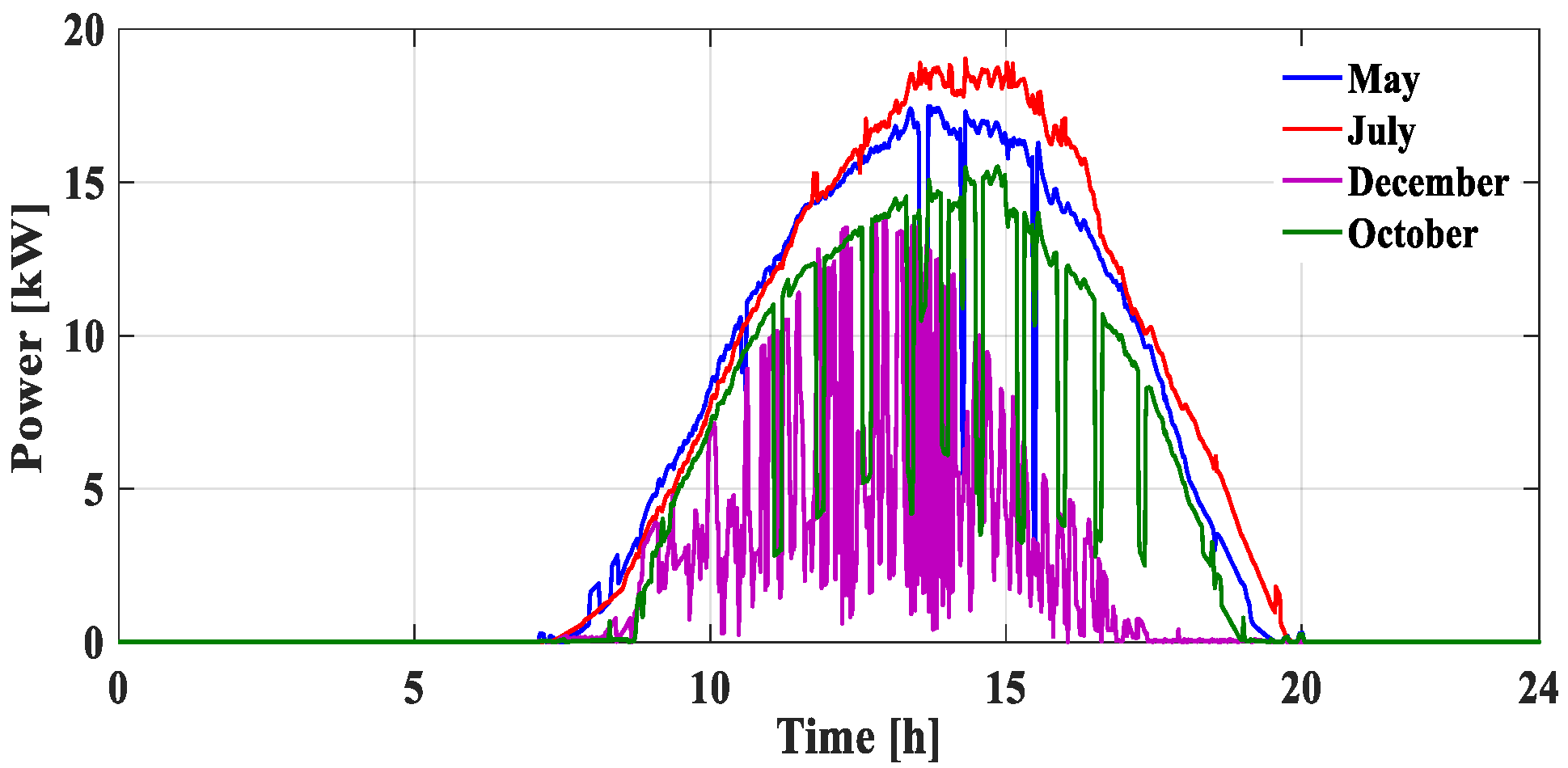
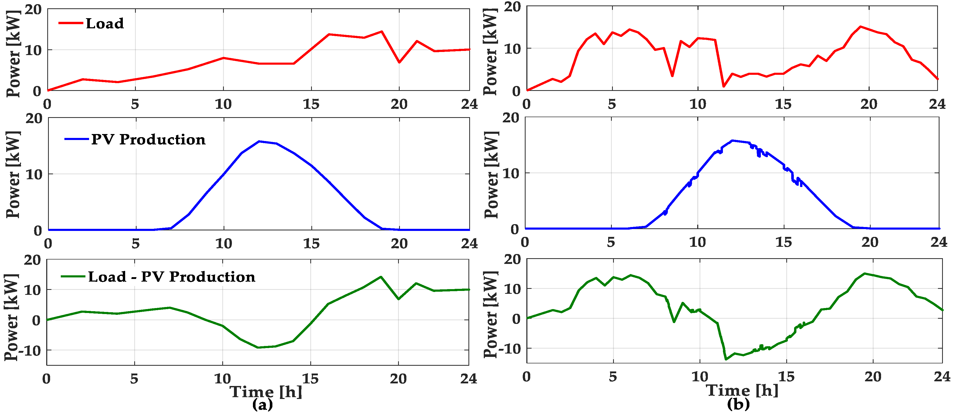
3.4. Load Profile
4. Energy Management Strategy
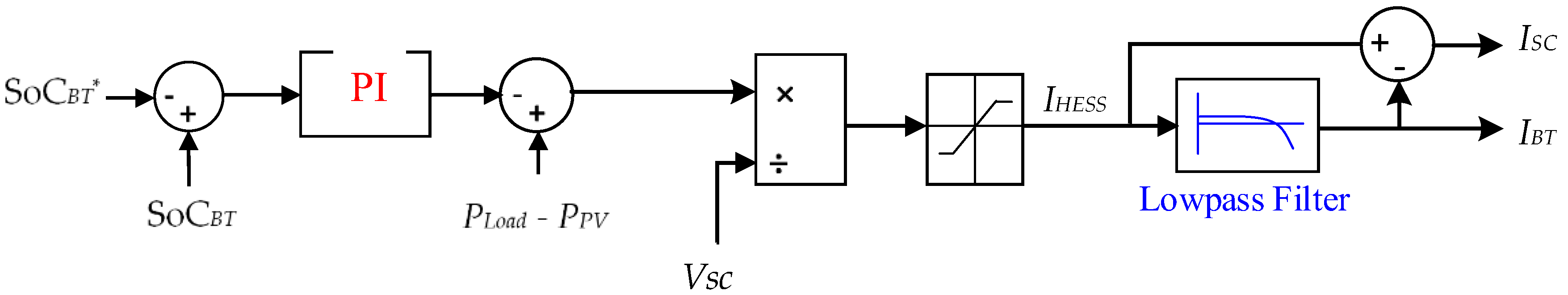
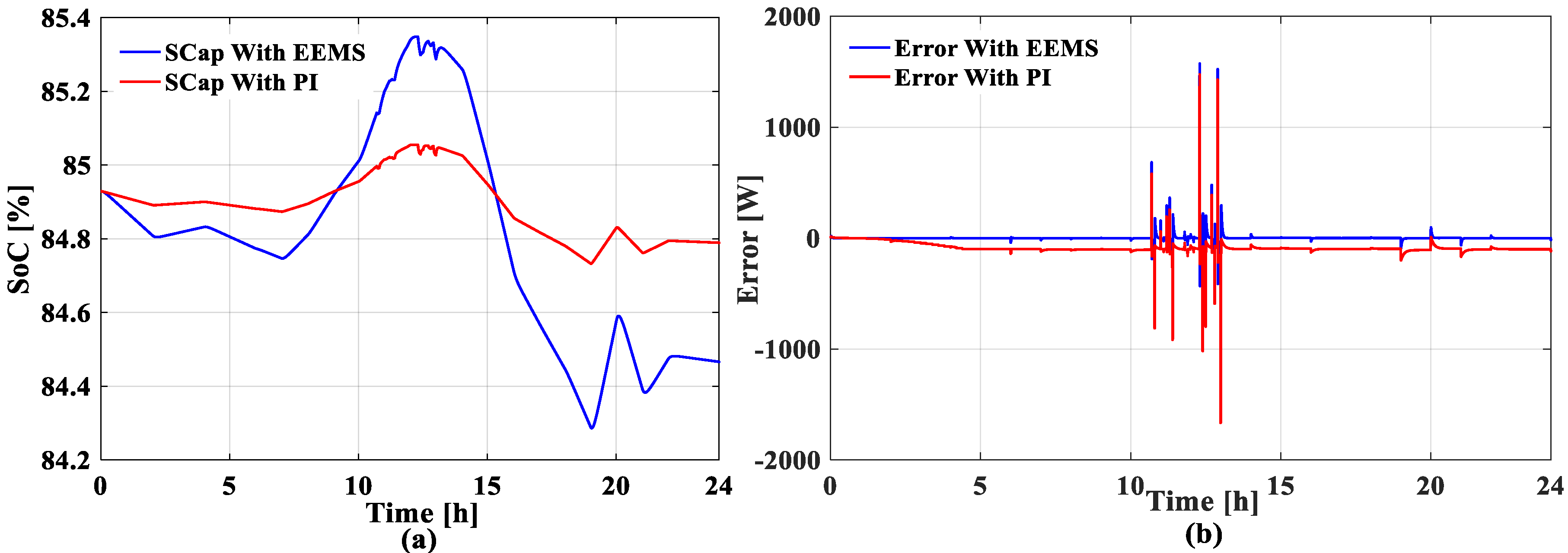
4.1. Classical PI Control Strategy
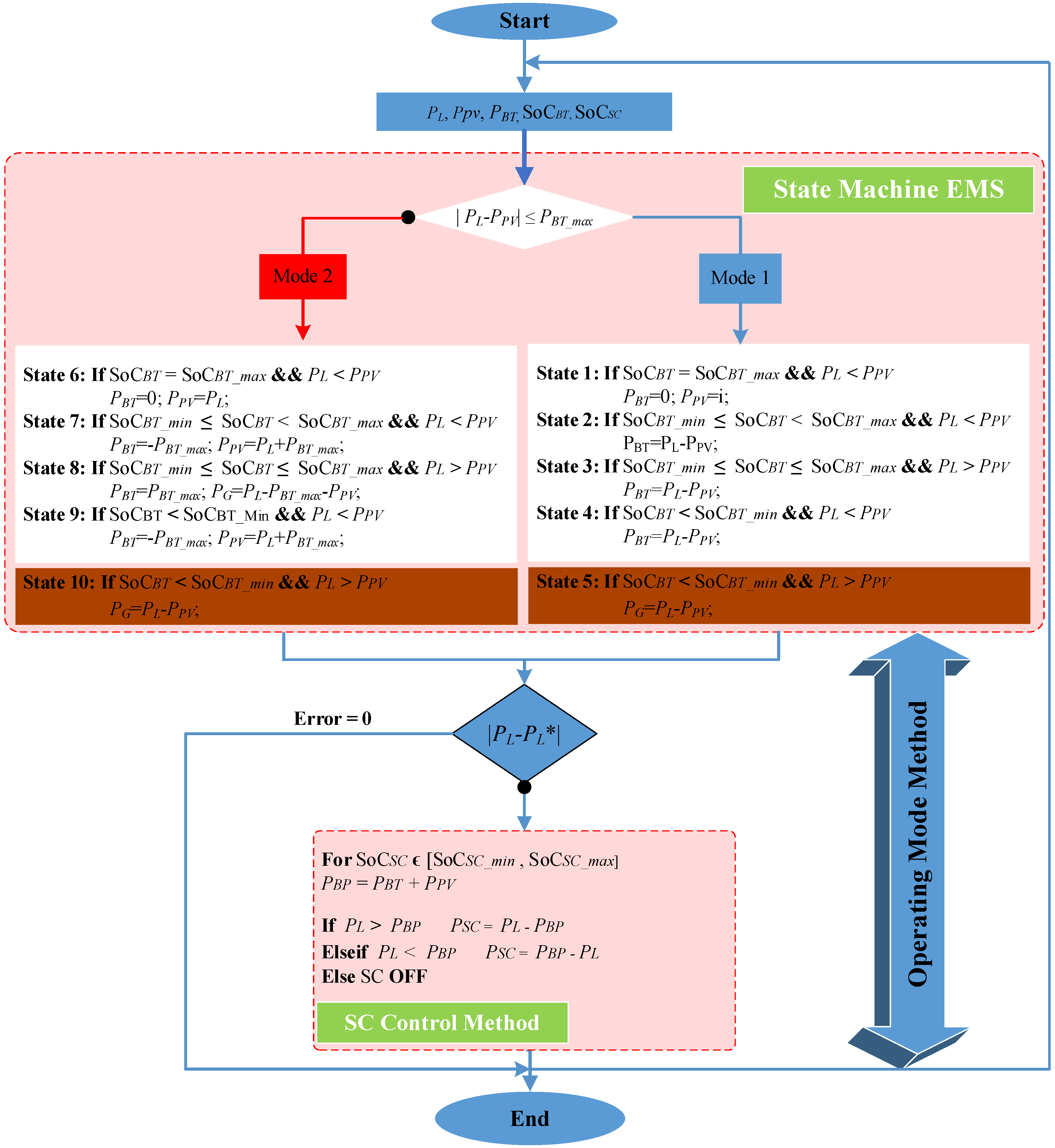
4.2. The Enhanced Energy Management Strategy (EEMS)
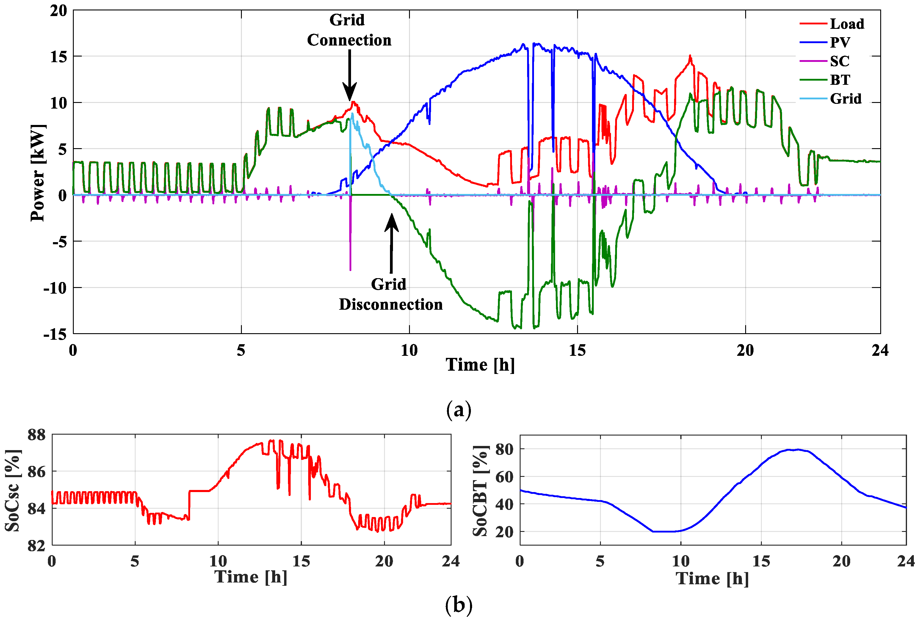
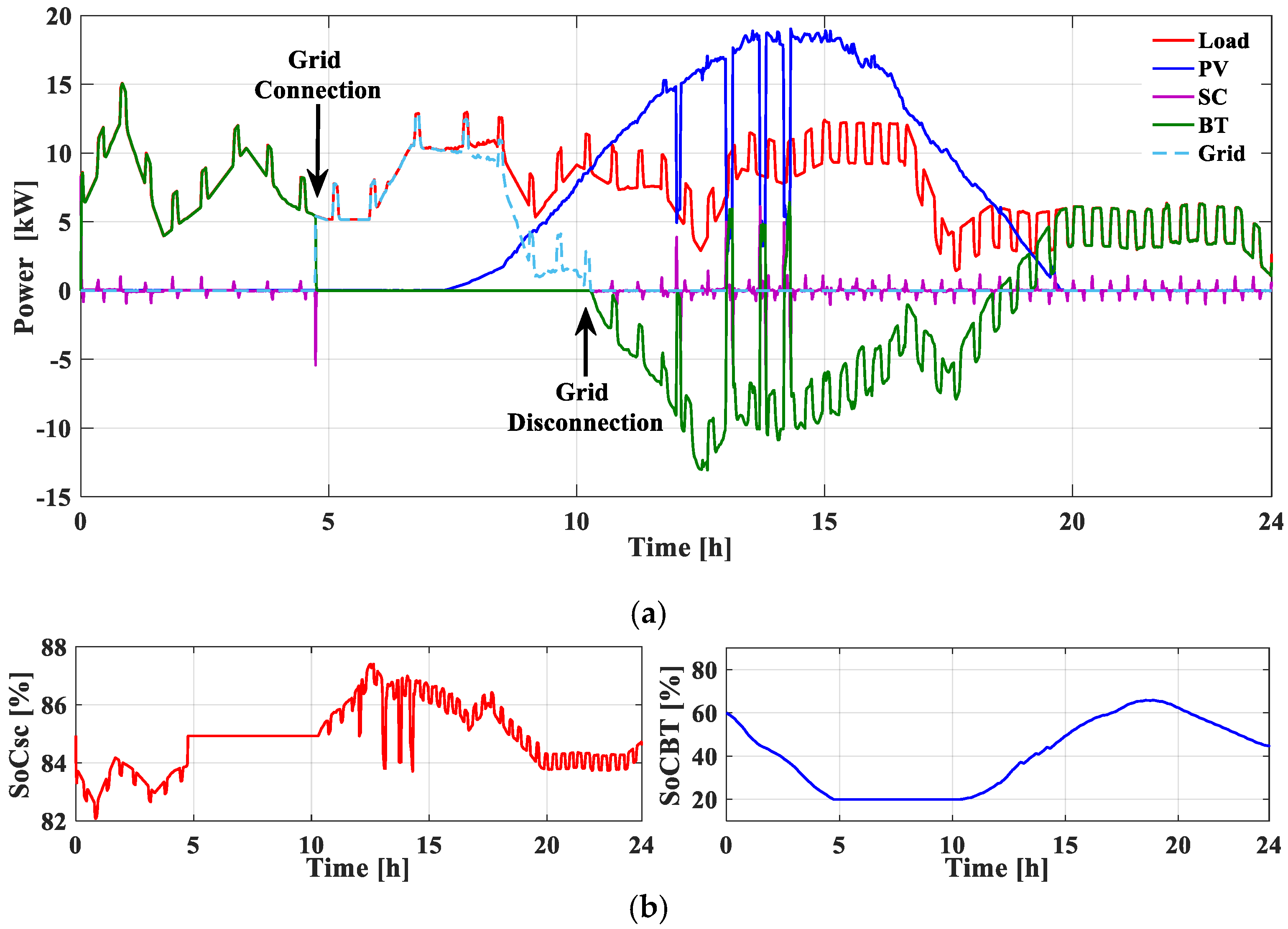
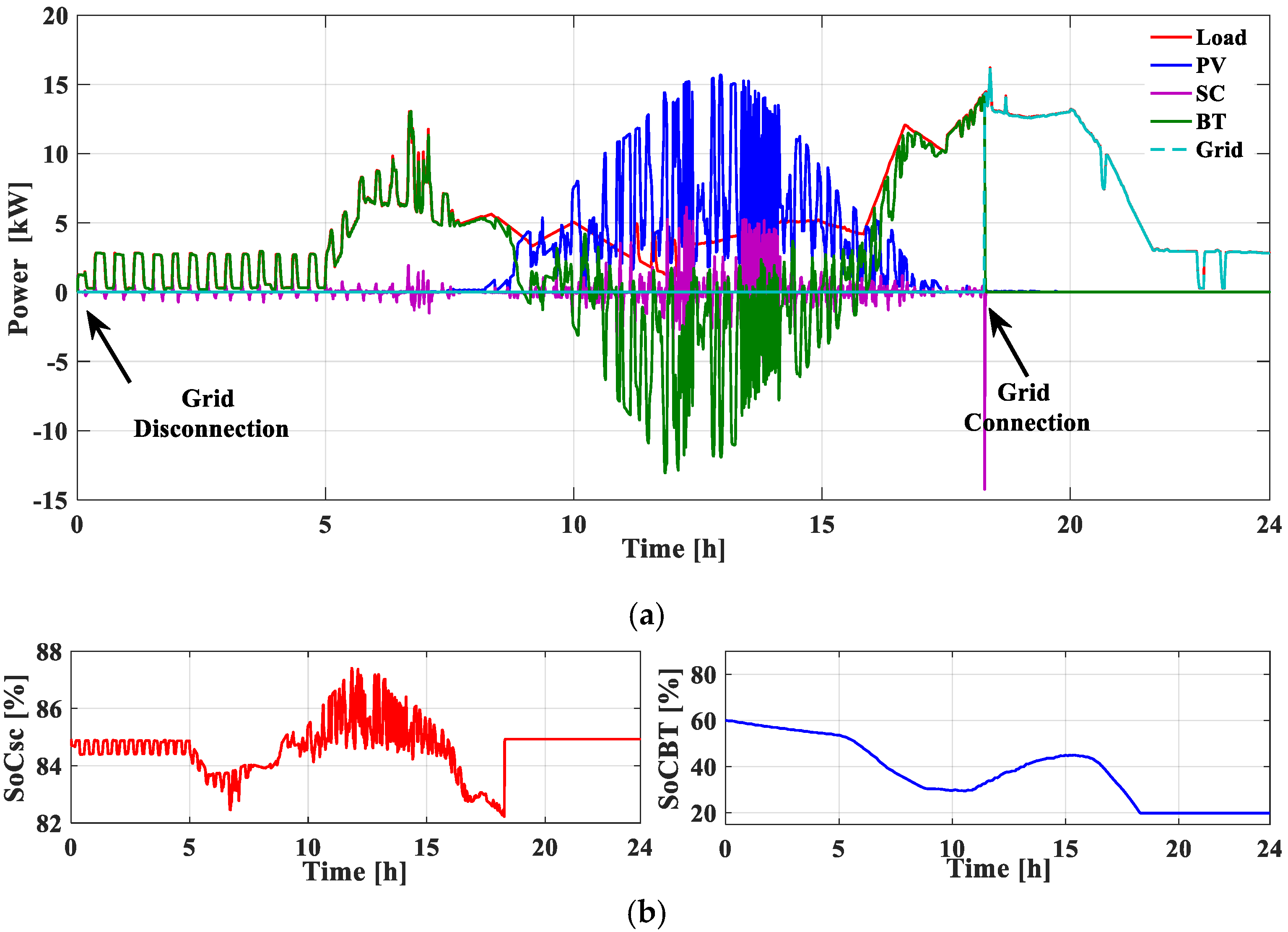
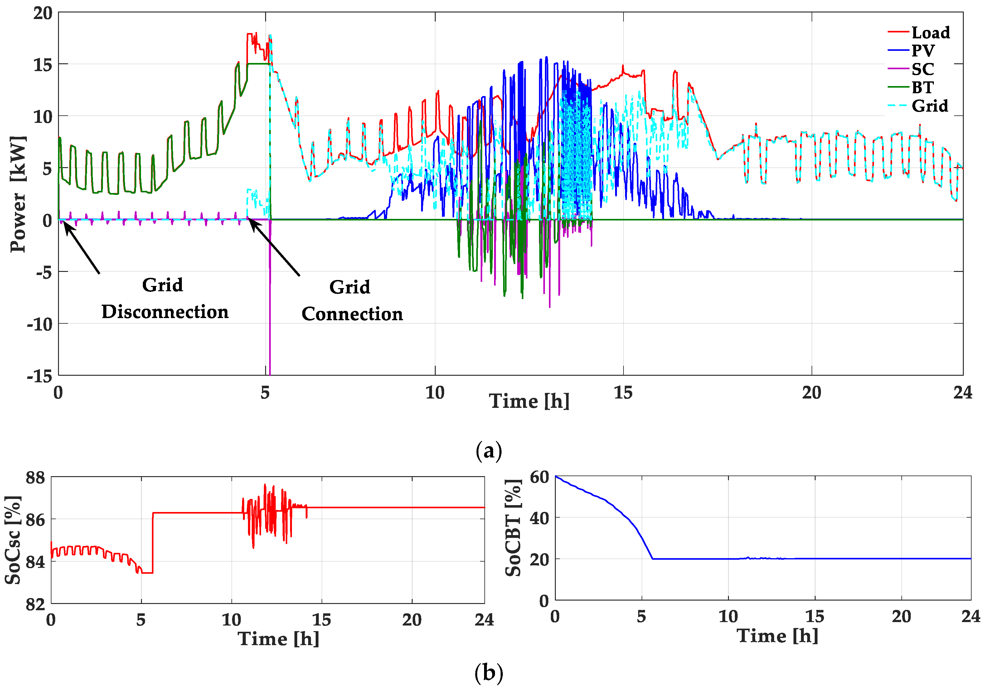
5. Results and Discussion
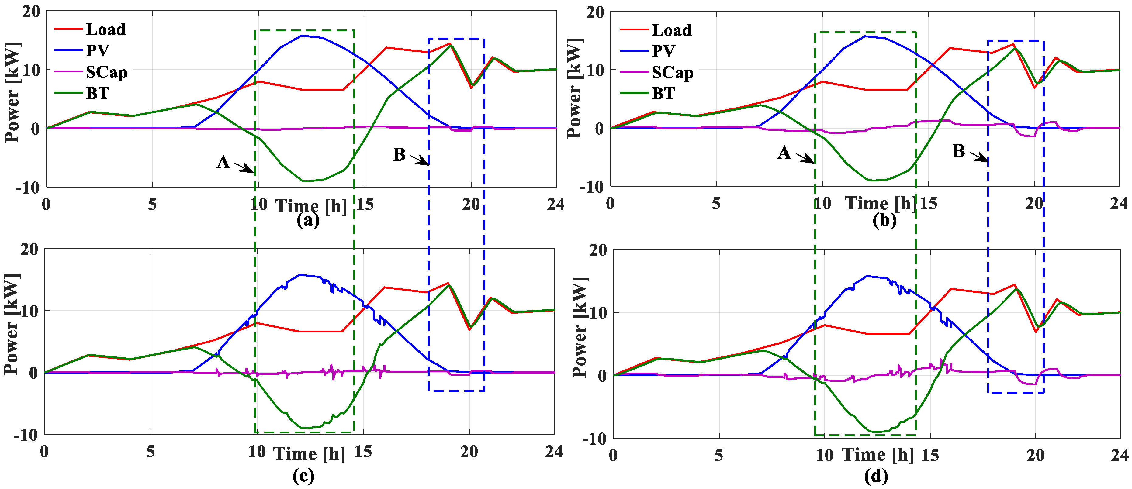
- Stand-alone mode: In this case, the EEMS system controls the excess or power deficit by storage means (BT and SC) while the system is disconnected from the grid.
- Grid-connected mode: In this case, the EEMS system controls the power excess or deficit by storage means (BT and SC) where SoCBT is kept above 20%; otherwise, the grid controls the deficit control.
6. Conclusions
Author Contributions
Funding
Conflicts of Interest
References
- Hussain, A.; Bui, V.H.; Kim, H.M. Microgrids as a resilience resource and strategies used by microgrids for enhancing resilience. Appl. Energy 2019, 240, 56–72. [Google Scholar] [CrossRef]
- Lashab, A.; Bouzid, A.; Snani, H. Comparative study of three MPPT algorithms for a photovoltaic system control. In Proceedings of the 2015 World Congress on Information Technology and Computer Applications (WCITCA), Hammamet, Tunisia, 11–13 June 2015. [Google Scholar]
- Lashab, A.; Sera, D.; Martins, J.; Guerrero, J.M. Model predictive-based direct battery control in PV fed quasi Z-Source inverters. In Proceedings of the 5th International Symposium on Environment-Friendly Energies and Applications (EFEA), Rome, Italy, 24–26 September 2018. [Google Scholar]
- Che, L.; Shahidehpour, M.; Alabdulwahab, A.; Al-Turki, Y. Hierarchical coordination of a community microgrid with AC and DC microgrids. IEEE Trans. Smart Grid 2015, 6, 3042–3051. [Google Scholar] [CrossRef]
- Barelli, L.; Bidini, G.; Bonucci, F.; Ottaviano, A. Residential micro-grid load management through artificial neural networks. J. Energy Storage 2018, 17, 287–298. [Google Scholar] [CrossRef]
- Pepermans, G.; Driesen, J.; Haeseldonckx, D.; Belmans, R.; D’haeseleer, W. Distributed generation: Definition, benefits and issues. Energy Policy 2005, 33, 787–798. [Google Scholar] [CrossRef]
- Pai, S.; Velaga, A.N.; Lindenberger, W.S.; Lai, W.Y.-C.; Cheung, K.P.; Baumann, F.H.; Chang, C.P.; Liu, C.T.; Liu, R.; Diodato, P.W.; et al. A manufacturable embedded fluorinated SiO2for advanced 0.25 μm CMOS VLSI multilevel interconnect applications. In Proceedings of the IEEE 1998 International Interconnect Technology Conference, San Francisco, CA, USA, 3 June 1998. [Google Scholar]
- Ustun, T.S.; Ozansoy, C.; Zayegh, A. Recent developments in microgrids and example cases around the world—A review. Renew. Sustain. Energy Rev. 2011, 15, 4030–4041. [Google Scholar] [CrossRef]
- Rodriguez-Diaz, E.; Vasquez, J.C.; Guerrero, J.M. Intelligent DC homes in future sustainable energy systems: When efficiency and intelligence work together. IEEE Consum. Electron. Mag. 2016, 5, 74–80. [Google Scholar] [CrossRef]
- Martins, J.; Spataru, S.; Sera, D.; Stroe, D.-I.; Lashab, A. Comparative study of ramp-rate control algorithms for PV with energy storage systems. Energies 2019, 12, 1342. [Google Scholar] [CrossRef] [Green Version]
- Lashab, A.; Sera, D.; Martins, J.; Guerrero, J.M. Multilevel DC-link converter-based photovoltaic system with integrated energy storage. In Proceedings of the 5th International Symposium on Environment-Friendly Energies and Applications (EFEA), Rome, Italy, 24–26 September 2018. [Google Scholar]
- Hirsch, A.; Parag, Y.; Guerrero, J. Microgrids: A review of technologies, key drivers, and outstanding issues. Renew. Sustain. Energy Rev. 2018, 90, 402–411. [Google Scholar] [CrossRef]
- Rodriguez-Diaz, E.; Palacios-Garcia, E.J.; Anvari-Moghaddam, A.; Vasquez, J.C.; Guerrero, J.M. Real-time energy management system for a hybrid AC/DC residential microgrid. In Proceedings of the 2017 IEEE Second International Conference on DC Microgrids (ICDCM), Nuremburg, Germany, 27–29 June 2017; pp. 256–261. [Google Scholar]
- Li, D.; Chiu, W.-Y.; Sun, H. Demand side management in microgrid control systems. Microgrid Adv. Control. Methods Renew. Energy Syst. Integr. 2017. [Google Scholar] [CrossRef]
- Dagdougui, H.; Ouammi, A.; Sacile, R. Towards a Concept of Cooperating Power Network for Energy Management and Control of Microgrids; Elsevier Inc.: Amsterdam, The Netherlands, 2016. [Google Scholar]
- Motapon, S.N.; Dessaint, L.A.; Al-Haddad, K. A robust H2-consumption-minimization-based energy management strategy for a fuel cell hybrid emergency power system of more electric aircraft. IEEE Trans. Ind. Electron. 2014, 61, 6148–6156. [Google Scholar] [CrossRef]
- Njoya Motapon, S.; Dessaint, L.A.; Al-Haddad, K. A comparative study of energy management schemes for a fuel-cell hybrid emergency power system of more-electric aircraft. IEEE Trans. Ind. Electron. 2014, 61, 1320–1334. [Google Scholar] [CrossRef]
- Yoon, Y.; Kim, Y.H. Effective scheduling of residential energy storage systems under dynamic pricing. Renew. Energy 2016, 87, 936–945. [Google Scholar] [CrossRef]
- Luthander, R.; Widén, J.; Nilsson, D.; Palm, J. Photovoltaic self-consumption in buildings: A. review. Appl. Energy 2015, 142, 80–94. [Google Scholar] [CrossRef] [Green Version]
- Parra, D.; Walker, G.S.; Gillott, M. Modeling of PV generation, battery and hydrogen storage to investigate the benefits of energy storage for single dwelling. Sustain. Cities Soc. 2014, 10, 1–10. [Google Scholar] [CrossRef]
- Pena-Bello, A.; Burer, M.; Patel, M.K.; Parra, D. Optimizing PV and grid charging in combined applications to improve the profitability of residential batteries. J. Energy Storage 2017, 13, 58–72. [Google Scholar] [CrossRef]
- Nan, S.; Zhou, M.; Li, G. Optimal residential community demand response scheduling in smart grid. Appl. Energy 2018, 210, 1280–1289. [Google Scholar] [CrossRef]
- Luna, A.C.; Diaz, N.L.; Graells, M.; Vasquez, J.C.; Guerrero, J.M. Mixed-integer-linear-programming-based energy management system for hybrid PV-wind-battery microgrids: Modeling, design, and experimental verification. IEEE Trans. Power Electron. 2017, 32, 2769–2783. [Google Scholar] [CrossRef] [Green Version]
- Pavković, D.; Lobrović, M.; Hrgetić, M.; Komljenović, A. A design of cascade control system and adaptive load compensator for battery/ultracapacitor hybrid energy storage-based direct current microgrid. Energy Convers. Manag. 2016, 114, 154–167. [Google Scholar] [CrossRef]
- Han, X.; Zhang, H.; Yu, X.; Wang, L. Economic evaluation of grid-connected micro-grid system with photovoltaic and energy storage under different investment and financing models. Appl. Energy 2016, 184, 103–118. [Google Scholar] [CrossRef]
- Vega, M.; Santamaria, F.; Rivas, E. Modeling for home electric energy management: A. review. Renew. Sustain. Energy Rev. 2015, 52, 948–959. [Google Scholar] [CrossRef]
- Aouzellag, H.; Ghedamsi, K.; Aouzellag, D. Energy management and fault tolerant control strategies for fuel cell/ultra-capacitor hybrid electric vehicles to enhance autonomy, efficiency and life time of the fuel cell system. Int. J. Hydrogen Energy 2015, 40, 7204–7213. [Google Scholar] [CrossRef]
- Lashab, A.; Sera, D.; Guerrero, J.M. A dual-discrete model predictive control-based MPPT for PV systems. IEEE Trans. on Power Electron. 2019, 34, 9686–9697. [Google Scholar] [CrossRef]
- Lashab, A.; Sera, D.; Guerrero, J.M.; Mathe, L.; Bouzid, A. Discrete model-predictive-control-based maximum power point tracking for PV systems: Overview and evaluation. IEEE Trans. Power Electron. 2018, 33, 7273–7287. [Google Scholar] [CrossRef]
- Bounechba, H.; Bouzid, A.; Snani, H.; Lashab, A. Real time simulation of MPPT algorithms for PV energy system. Int. J. Electr. Power Energy Syst. 2016, 83, 67–78. [Google Scholar] [CrossRef] [Green Version]
- Bouabdallah, A.; Olivier, J.C.; Bourguet, S.; Machmoum, M.; Schaeffer, E. Safe sizing methodology applied to a standalone photovoltaic system. Renew. Energy 2015, 80, 266–274. [Google Scholar] [CrossRef]
- Bouabdallah, A.; Bourguet, S.; Olivier, J.C.; Machmoum, M. Optimal sizing of a stand-alone photovoltaic system. In Proceedings of the 2013 International Conference on Renewable Energy Research and Applications (ICRERA), Madrid, Spain, 20–23 October 2013. [Google Scholar]
- Bugár, M. A Dynamic Battery Model Considering the Effects of the Temperature and Capacity Fading; Posterus. Available online: https://www.posterus.sk/?p=13560&output=pdf (accessed on 10 March 2020).
- Le Moigne, P.; Rizoug, N.; Bartholomeüs, P.; Chaaban, K.; Mesbahi, T.; Khenfri, F. Dynamical modeling of Li-ion batteries for electric vehicle applications based on hybrid particle swarm–nelder–mead (PSO–NM) optimization algorithm. Electr. Power Syst. Res. 2015, 131, 195–204. [Google Scholar]
- Dai, H.; Wei, X.; Sun, Z.; Wang, J.; Gu, W. Online cell SOC estimation of Li-ion battery packs using a dual time-scale Kalman filtering for EV applications. Appl. Energy 2012, 95, 227–237. [Google Scholar] [CrossRef]
- Tremblay, O.; Dessaint, L.A. Experimental validation of a battery dynamic model for EV applications. World Electr. Veh. J. 2009, 3, 289. [Google Scholar] [CrossRef] [Green Version]
- Shi, L.; Crow, M.L. Comparison of ultracapacitor electric circuit models. In Proceedings of the 2008 IEEE Power and Energy Society General Meeting—Conversion and Delivery of Electrical Energy in the 21st Century, Pittsburgh, PA, USA, 20–24 July 2008. [Google Scholar]
- Li, W.; Zhu, X.; Cao, G. Modeling and control of a small solar fuel cell hybrid energy system. J. Zhejiang Univ. A 2007, 8, 734–740. [Google Scholar] [CrossRef]
- Murray, D.; Stankovic, L.; Stankovic, V. Data descriptor: An electrical load measurements dataset of United Kingdom households from a two-year longitudinal study. Sci. Data 2017, 4, 1–12. [Google Scholar] [CrossRef] [Green Version]
- STEG Energies Renouvelables, STEG Energies Renouvelables. Available online: http://www.steg-er. com.tn/ (accessed on 26 May 2020).


| Parameter | Symbol | Value |
|---|---|---|
| Photovoltaic Panel (PV) | ||
| Peak power (kW) | Ppv_max | 18 |
| Surface (m2) | Spv | 40 |
| Nominal efficiency (%) | ηmanuf | 12.35 |
| Reference temperature. (°C) | Tr | 20 |
| Nominal cell temperature. (°C) | TNOCT | 47 |
| Nominal ambient temperature. (°C) | Ta,NOCT | 20 |
| Nominal solar radiation (W/m2) | GNOCT | 800 |
| Temperature coefficient (%/°C) | βPV | 0.45 |
| MPPT + converter efficiency (%) | ηconv | 95 |
| Battery (BT) | ||
| State of charge max (%) | SoCBT_Max | 80 |
| State of charge min (%) | SoCBT_Min | 20 |
| Battery Capacity (Ah) | QBat | 45 |
| Battery power (kW) | (PBT_min., PBT_max.) | (−15,15) |
| Super-Capacitor (SC) | ||
| State of charge max (%) | SoCSC_Max | 90 |
| State of charge min (%) | SoCSC_Min | 10 |
| Resistance SC (Ω) | RSC | 6.3 × 10⁻³ |
| Capacitance SC (F) | C0 | 165 |
| PI controller | ||
| Proportional gain | Kp | 10 |
| Integral gain | Ki | 10 |
| Output limits: (Upper Lower) | (80,100) |
© 2020 by the authors. Licensee MDPI, Basel, Switzerland. This article is an open access article distributed under the terms and conditions of the Creative Commons Attribution (CC BY) license (http://creativecommons.org/licenses/by/4.0/).
Share and Cite
Dhifli, M.; Lashab, A.; Guerrero, J.M.; Abusorrah, A.; Al-Turki, Y.A.; Cherif, A. Enhanced Intelligent Energy Management System for a Renewable Energy-Based AC Microgrid. Energies 2020, 13, 3268. https://doi.org/10.3390/en13123268
Dhifli M, Lashab A, Guerrero JM, Abusorrah A, Al-Turki YA, Cherif A. Enhanced Intelligent Energy Management System for a Renewable Energy-Based AC Microgrid. Energies. 2020; 13(12):3268. https://doi.org/10.3390/en13123268
Chicago/Turabian StyleDhifli, Mehdi, Abderezak Lashab, Josep M. Guerrero, Abdullah Abusorrah, Yusuf A. Al-Turki, and Adnane Cherif. 2020. "Enhanced Intelligent Energy Management System for a Renewable Energy-Based AC Microgrid" Energies 13, no. 12: 3268. https://doi.org/10.3390/en13123268