Review

Advanced Laboratory Testing Methods Using Real-Time Simulation and Hardware-in-the-Loop Techniques: A Survey of Smart Grid International Research Facility Network Activities

by
Juan Montoya
1,*,
Ron Brandl
1,2,
Keerthi Vishwanath
2,
Jay Johnson
3,
Rachid Darbali-Zamora
3,
Adam Summers
3,
Jun Hashimoto
4,
Hiroshi Kikusato
4,
Taha Selim Ustun
4,
Nayeem Ninad
5,
Estefan Apablaza-Arancibia
5,
Jean-Philippe Bérard
5,6,
Maxime Rivard
5,6,
Syed Qaseem Ali
6,
Artjoms Obushevs
7,
Kai Heussen
8,
Rad Stanev
9,
Efren Guillo-Sansano
10,
Mazheruddin H. Syed
10,
Graeme Burt
10,
Changhee Cho
11,
Hyeong-Jun Yoo
11,
Chandra Prakash Awasthi
12,
Kumud Wadhwa
12 and
Roland Bründlinger
13
add Show full author list remove Hide full author list
1
Fraunhofer IEE, 34119 Kassel, Germany
2
DERLab, 34119 Kassel, Germany
3
Sandia National Laboratories, Albuquerque, NM 87123, USA
4
National Institute of Advanced Industrial Science and Technology, Fukushima 963-0298, Japan
5
CanmetENERGY, Natural Resources Canada (NRCan), Varennes, QC J3X 1S6, Canada
6
OPAL-RT Technologies, Montreal, QC H3K 1G6, Canada
7
ZHAW, IEFE, 8401 Winterthur, Switzerland
8
DTU, Kgs. 2800 Lyngby, Denmark
9
TU-Sofia, 1756 Sofia, Bulgaria
10
Institute for Energy and Environment, Electronic and Electrical Engineering Department, University of Strathclyde, Glasgow G1 1XQ, UK
11
KERI, Changwon-si 51543, Korea
12
Power Grid Corporation of India Limited, Gurgaon 122001, India
13
Austrian Institute of Technology, 1210 Vienna, Austria
*
Author to whom correspondence should be addressed.
Energies 2020, 13(12), 3267; https://doi.org/10.3390/en13123267
Submission received: 20 May 2020 / Revised: 16 June 2020 / Accepted: 22 June 2020 / Published: 24 June 2020
(This article belongs to the Special Issue Advancements in Real-Time Simulation of Power and Energy Systems)

Abstract

:
The integration of smart grid technologies in interconnected power system networks presents multiple challenges for the power industry and the scientific community. To address these challenges, researchers are creating new methods for the validation of: control, interoperability, reliability of Internet of Things systems, distributed energy resources, modern power equipment for applications covering power system stability, operation, control, and cybersecurity. Novel methods for laboratory testing of electrical power systems incorporate novel simulation techniques spanning real-time simulation, Power Hardware-in-the-Loop, Controller Hardware-in-the-Loop, Power System-in-the-Loop, and co-simulation technologies. These methods directly support the acceleration of electrical systems and power electronics component research by validating technological solutions in high-fidelity environments. In this paper, members of the Survey of Smart Grid International Research Facility Network task on Advanced Laboratory Testing Methods present a review of methods, test procedures, studies, and experiences employing advanced laboratory techniques for validation of range of research and development prototypes and novel power system solutions.

1. Introduction

Increasing deployments of distributed energy resources (DER) and smart grid technologies in cyber–physical energy systems, has driven the scientific community and power industries to develop novel technologies. Such technology allows the energy systems to be operated and controlled more optimally, however, its inclusion brings challenges to the power system stability, operation, control, protection schemes, device interoperability, substation automation, wide-area protection mechanisms, cybersecurity, and additional reliance on Internet of Things (IoT) devices, to name a few examples. In order to ensure a smooth transition to a more distributed grid with higher penetration of renewable energy units, new procedures and methods for testing and validating interoperability, reliability, and stability must be developed.
To address this need, researchers have developed advanced laboratory evaluation methods based on real-time simulation (RTS) and Hardware-in-the-Loop (HIL) including: Power Hardware-in-the-Loop (PHIL), Controller Hardware-in-the-Loop (CHIL), Power System-in-the-Loop (PSIL), and co-simulation that improve the fidelity of smart grid simulation tools. Now physical equipment or controllers can be inserted into real-time (RT) or faster than RT simulations to validate equipment performance characteristics. The development of multi-domain simulation environment is also providing new information about the interactions of cyber–physical environments.
To draw a baseline for the reader, a brief explanation of the definitions of RTS and HIL techniques mentioned in this review are provided:
  • RTS is a simulation, which is solely digitally executed in a real-time way on an RTSM.
  • Co-simulation is a test setup that combines at least two different software tools executed on one or more computational systems.
  • HIL is a test setup that combines a real-time simulated system with a physical hardware component or system, where interfaces with physical and simulated systems enabling closed loop interactions.
  • Controller HIL or CHIL is a HIL technique where the sensors and actuators of a physical controller are interfaced with a real-time simulation.
  • Power HIL or PHIL is a HIL setup, where at least one of the bi-directional interfaces of a setup exchanges power with real, physical power hardware through a Power Amplifier.
  • Power System in-the-Loop or PSIL is a novel HIL concept where more than two domains interface each other in order to perform holistic experiments, e.g., a connection between a virtual simulated system (where RTS and co-simulation occur), a controller component (where CHIL occurs), and physical power system (where PHIL occurs).

1.1. Motivation of the Review

This review brought together technical experts from multiple investigation areas to identify state-of-the-art testing method trends. The Smart Grid International Research Facility Network (SIRFN) is a worldwide network of smart grid research and test-bed facilities participating under the Annex 5 of the International Smart Grid Action Network (ISGAN). The testing and evaluation capabilities of SIRFN allows the international community to enable: improved design, implementation, and testing of smart grids and their functionalities, including the reliable integration of clean energy technologies.
The SIRFN task on Advanced Laboratory Testing Methods (ALTM) addresses state-of-the-art testing procedures and develops recommendations on future testing techniques of electrical power systems and their domains. SIRFN implements new recommendations by collaborative activities among test infrastructures and identifies potential common activities for future application of advanced methodologies within the network. This community has a good perspective on the quickly evolving landscape of novel simulation techniques such as RTS (PHIL, CHIL, PSIL, etc.) and is in an excellent position to identify promising upcoming advanced laboratory testing methods for other research teams and the power system industry.

1.2. Review Structure

In this survey, state-of-the-art capabilities afforded by new simulation tools are enumerated for applications covering power system design, smart grid control, power electronics, communications, and cybersecurity. Specifically, this review surveyed recent activities of the SIRFN ALTM task participants about ongoing and recently finished ALTM, RTS, and HIL research techniques, including the following topics:
  • Interfacing methods of PHIL, CHIL, and PSIL simulation;
  • HIL testing of power system protection and control;
  • HIL testing of smart grid/microgrid controllers, energy management systems, and power electronic converters;
  • Co-simulation and RTS integration;
  • Geographically distributed HIL and RTS;
  • Industrial experiences and HIL in standardized testing.
Each of these topics forms a separate section, which provides a brief introduction and then reports on specific experiences and activities by the SIRFN ALTM members in the additional subsections. Thereafter, a summary of experiments is organized in a table, gathering the hardware used in the reported activities, to give the reader an overview of the equipment used in HIL experiments. In addition, a grouping of the literature and references used for each section is tabulated and presented. Finally, a conclusion and future outlook is included, thereby the authors express their ideas about the review from the perspective of the SIRFN ALTM community.

2. Interfacing Methods of PHIL, CHIL, and PSIL Simulation

2.1. Introduction

RTS and PHIL technologies are present in activities covering (a) component testing, (b) power system stability studies (as risk-free and close-to-reality alternative to field tests), and (c) development and verification of new control strategies. Establishing a seamless interface between an RTS model and physical devices is a technical challenge because the design of the interfacing method impacts both stability and accuracy of the RT control system [1,2]. For this, an interface algorithm (IA) is implemented between the real-time simulation machine (RTSM) and power amplifier (PA) to ensure a stable and accurate range of operation.
The typical temporal resolution of a PHIL experiment for electro-mechanical transients (EMT) is in the range of 10–100 microseconds, but the interactions between large-scale and local dynamics as well as wide-area and local control systems increases drastically in proportion with the number of nodes of the system. The large-scale dynamics are “slow” (from milliseconds to seconds) and typically represented by root mean squared (RMS) values. One solution to combine these environments, is to create PHIL environments which represent RMS simulations and convert the fast dynamics of the interfaced power equipment to RMS values. It should be noted though, that many PHIL simulations are executed in the fast domain with time steps between 40–120 microseconds. In case of capturing slow dynamics, the Power System-in-the-Loop (PSIL) testing concept [3] can be implemented to exploit the use of quasi-static and quasi-dynamic [4,5,6] time domain analysis combined with PHIL.
This section classifies the interfacing methods of PHIL, CHIL, and PSIL simulation in two main topics:
1
Interface Algorithms for Fast Dynamics: Nowadays, the accuracy and stability of several IAs have been analyzed in detail [1,2,7,8,9,10,11,12], including: the ideal transformer model (ITM), partial circuit duplication (PCD), transmission line model (TLM), damping impedance method (DIM), time variant first-order approximation (TFA), and advanced ideal transformer model (AITM); being the ITM and DIM are the most widely used techniques for connecting power equipment to a PHIL RTS.
2
PHIL Integration at Slow Time Scales: For application areas where the concerned dynamics are slow (RMS values calculated using tens to hundreds of cycles), the technical requirements of the HIL integration can be simplified, that reduces hardware cost and improves scalability. Examples of system behaviors and relevant functions in these time scales are: power and energy management, active and reactive power balancing, demand side management, voltage control strategies, and determination of the proximity to operating limits. By the use of the PSIL concept, this review present two methods: (a) quasi-dynamic PHIL in Section 2.2.3 and (b) quasi-static PHIL in Section 2.2.4.

2.2. Reported Experiences and Activities from SIRFN ALTM Members

2.2.1. Power Amplifier Characterization for RTS

The PA plays a vital role in PHIL simulations. In order to assess the accuracy and stability of PHIL simulations, accurate modeling of the PA or grid simulator must be available. CanmetENERGY and OPAL-RTTM have been collaborating to develop a grid simulator characterization environment. This environment performs frequency sweeps with different operating voltages. The resulting magnitude and phase response data, generates a number of Bode plots and transfer functions which realistically model the amplifiter behavior. This realistic amplifier model can be used to assess the stability of an RT power system simulation before the actual PHIL study is conducted.
As each amplifier is different, amplitude step tests were performed to determine the intrinsic amplifier delays and the communication delays of the system. Once these delays were identified, they were factored out of the recorded data, and included in the transfer function modeling. Since this modeling work has the ultimate goal of providing an amplifier model for all operating conditions, work remains to find a generic methodology to characterize different types of PAs with sufficient accuracy. This activity is an ongoing research and further results might affect the exact implementation of this method.

2.2.2. Stability and Accuracy Comparison for Different Interfacing Methods

In [12], the voltage ideal transformer method (ITM) and the voltage damping impedance method (DIM) were compared during unity and non-unity power factor setting and curtailed real power levels to a baseline, when connecting a physical photovoltaic (PV) inverter to a PHIL simulation. The ITM and DIM methods generally, in simulation, have a low pass filter (LPF) on the output of the RTS to increase stability of the system when the PV inverter connects. The discrete time step of the simulation and LPF introduce a phase shift on the voltage output to the PA. This phase voltage shift injects artificially created or synthetic reactive power into the simulation at the point of connection in the RTSM. A low pass filter lead compensator (LPF LD) can be used to tune the introduced phase shift to minimize the synthetic reactive power injection in the simulation without removing the characteristics of the device under test (DuT). Results from [12] are shown in Table 1. The average error represents the summation of each individual error compared to a baseline, divided by the total number of tests. The execution cycle is the percent of time spent to compute all tasks of the model. The major computation time is expressed in a percentage of time spent by the model to perform block calculations including discrete and continuous state calculations. Each interface method takes computational effort to implement. Knowing the trade-off between computational usage and model accuracy empowers the user to select the appropriate interfacing method for the simulation.

2.2.3. Quasi-Dynamic PHIL

To perform simulations at the continental scale, the electrical dynamics need to be simplified. When dealing with multiple node power systems, the conventional approach solves a full set of differential equations in RT resulting in a significant computational burden. One option to overcome this issue is the so-called “quasi-dynamic” modeling approach for slow dynamics time domain analysis using modified nonlinear algebraic equations [5,6]. The quasi-dynamic PHIL analysis is typically used for long term power system behavior studies covering the time domains from several minutes to several hours or even days where the fast transients are considered to have settled down (to steady state) within the period of each time step.
To represent the power system dynamics depending on the application, a single or several (suitable for power system split and re-synchronization phenomena studies) mass dynamic models could be additionally used at a lower computational cost. This combination provides fast RT computation of the voltage magnitude, phase, and frequency within each individual node of the power system. This approach could be successfully used for large analyses of the interaction between one or several DuTs and the bulk power system.
The test set up at the Power System Stability Laboratory of the Technical University of Sofia (TU-Sofia) for testing Power System Stability support functions of active micro- and nanogrids, is one typical application of this approach. The Figure 1a shows the laboratory setup of a micro/nanogrid model consisting of: (a) programmable grid forming unit, (b) multi-functional laboratory transformer, (c) physical power line emulator, (d) PV emulator, (e) maximum power point charge controller, (f) bidirectional converter, (g) battery storage, (h) smart load controller, (i) physical model of hydro power plant, (k) motor generator sets with controls emulating different types of generation, and (d) a supervisory control and data acquisition (SCADA) system recording the system parameters.
While power system stability used to be widely accepted as a Bulk Power System (macrogrid) problem, the micro-, mini-, and nanogrid concepts which are feasible today allow more efficient and reliable system stability support functions based on local and distributed control [13]. To determine the impact on the macrogrid stability and the right settings of this control, a PHIL with the architecture shown in Figure 1b is used. It consists of a central RTSM representing the macrogrid using the STATUS quasi-dynamic and dynamic software. The STATUS quasi-dynamic module provides power flow and voltage stability analysis with a rich set of detailed stability indicators. Combined with the STATUS single/several mass dynamic model the frequency dynamics are given. Through the grid-forming unit the voltage and frequency (U,f) signals are amplified and transferred to the micro/nanogrid power DuT. In each RT time step, the computed power system stability indicators provide feedback on the efficiency of the actions performed by the local control.
Theoretically, the architecture is open and if another “i”-th distinct micro/nanogrid needs to be involved, a (U,f) signal with a time delay corresponding to the phase angle δ i could be sent from the central RTS to another grid-forming unit.

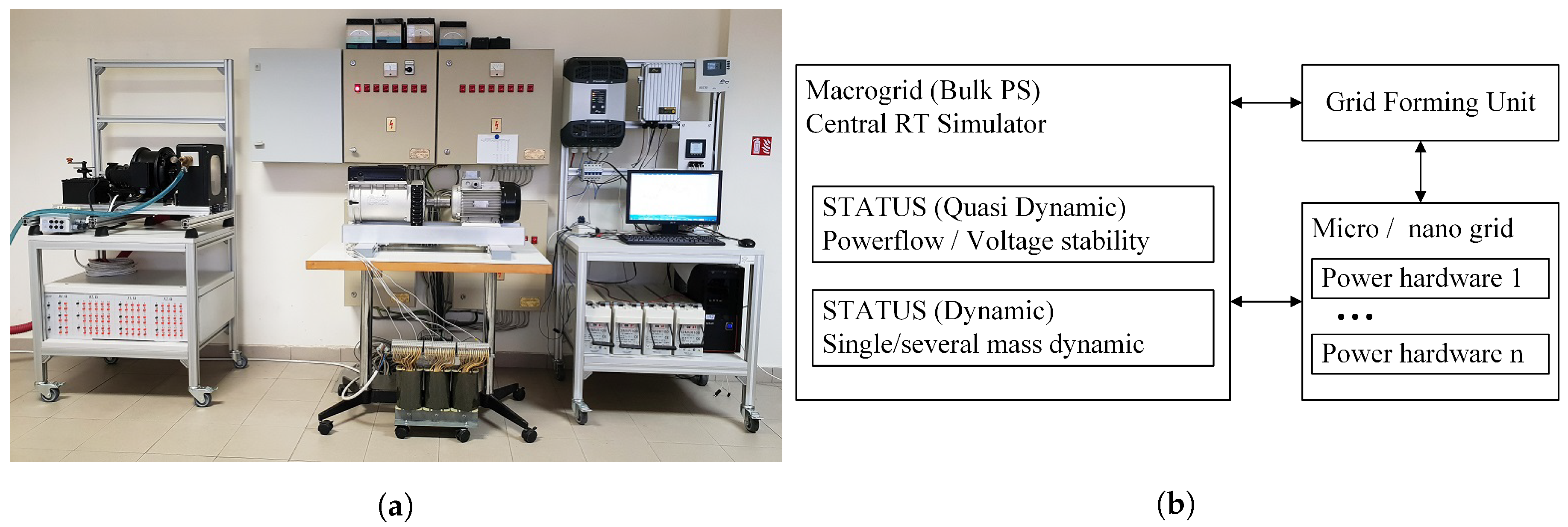
2.2.4. Quasi-Static PHIL

A scale-up on the hardware side of the HIL setup can be achieved, when the requirements of dynamic capabilities of the interfacing converter are reduced. Such a setup is relevant when interactions among several hardware components (e.g., DER) in a physical low-voltage distribution network, need to be investigated when they are coupled to medium and high voltage network dynamics. The PSIL concept [3] can be used for: use cases with slow voltage dynamics and interactions among DER controllers, inverters and upstream controls, and dispatch of coordinated voltage control setpoints, among others. Similar interfacing challenges are considered in remote or geographically distributed PHIL setups, as discussed in Section 6 and [14,15].
An illustration of this setup is found in Figure 2. Here, the RTSM uses as PA a (slow, ∼10 Hz update rate) grid-forming converter and similarly infrequent, asynchronous, and non-lockstep measurements; the grid-forming converter is connected to a low-voltage feeder and loads with different responses to voltage and frequency variations. The simulation interface needs therefore to accommodate an asymmetric coupling with update-rates differing by several orders of magnitude.
The technical setup involves:
  • a RTSM to simulate the relevant high and/or medium voltage simulation elements, and an interfacing component;
  • a physical interfacing device such as a controllable grid-forming converter which can set frequency and voltage;
  • a sufficiently fast RMS measurement at the interface device or its local bus.
Mathematically, the coupling is based on the ITM IA. In it, voltage and frequency are set by the RTSM model, while the RMS current and the phase ( I , c o s ϕ ) are the feedback set by the physical branch. The exchanged signals are as follows:
  • the RTSM system sends voltage and frequency RMS setpoints;
  • the Interface device (grid-forming component of the lab) realizes these setpoint with some dynamic delay;
  • the RMS P and Q values (or I, c o s ϕ ) are measured at the interface component, and transmitted to the RTSM component.
In this setup, the physical interface voltage and the current feedback are out-of-step during transients due to the hardware and software physical delays. Experiment designs account for this delay and consider only quasi-static phenomena: Relevant dynamics are simulated on the hardware power system components at slower time scales of 100 milliseconds or longer, relevant to energy management considerations, and voltage control coordination.
Due to the difference of update rates between RTSM at 20 kHz and the physical system operating at about 2 Hz, a multi-rate interface technique is necessary. Further, to ensure rapid convergence the long and non-deterministic delays between hardware (measurement, 10 Hz, 10 ms jitter; actuation 0.5–2 Hz) and RTSM elements are accounted for by suitable interface algorithms. Compensation methods enable accelerated convergence to steady state values. Two interfacing methods are described and evaluated in [16]. Due to the suitability for time delays, quasi-static PHIL methods are also applicable to geographically distributed setups, as further discussed in Section 6.1.2.

3. HIL Testing of Power System Protection and Control

3.1. Introduction

With growing installations of DER and the inclusion of the microgrid (MG) concept to enhance power system reliability, challenges appear in protection and control of transmission and distribution power systems. These problems are associated with additional fault current sources, increase of the total short-circuit level in the grid, and the presence of microprocessor based relays or Intelligent Electronic Devices (IEDs) [17]. This increases the threat to protection schemes due to: blinding of feeder protection, sympathetic tripping, failed reclosing, unintentional islanding, and recloser-fuse miscoordination [17,18,19], driving the protection and control engineers to re-evaluate long-established practices, as well as the way the relays are tested and certified. Adaptive protection is a protection strategy that is widely studied by the scientific community which tries to tackle some of these protection issues by adjusting protection equipment set points based on system operations [17,20,21,22,23]. The modeling of faults and protection strategies also needs to be studied and verified with transients (EMT simulations), which makes PHIL a good option to validate fault behaviors [24,25]. Finally, the requirements to certify such IEDs for the new power-system needs, requires frameworks suitable for close-to-reality testing, bringing an opportunity for HIL techniques to be implemented as a solution, like in [26]. Other alternatives for control and management of the power grid, such as wide area control by the use of synchrophasors and phasor measurement units (PMUs), is providing new reliability and controllability benefits to the power system [27]. It is important to have the capability to control and monitor the system in order to perform actions on the power system, such as the re-synchronization of an islanded MG [28], ensuring the conditions and requirements of local/international codes like the IEEE Std. 1547 [29]; or to dampen power systems oscillation by the inclusion of power system stabilizer strategies with PMU measurements [30].

3.2. Reported Experiences and Activities from SIRFN ALTM Members

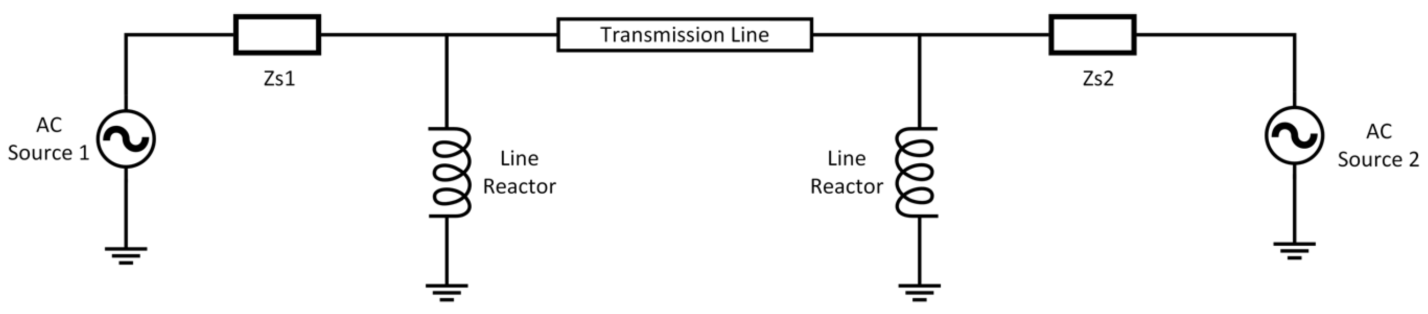
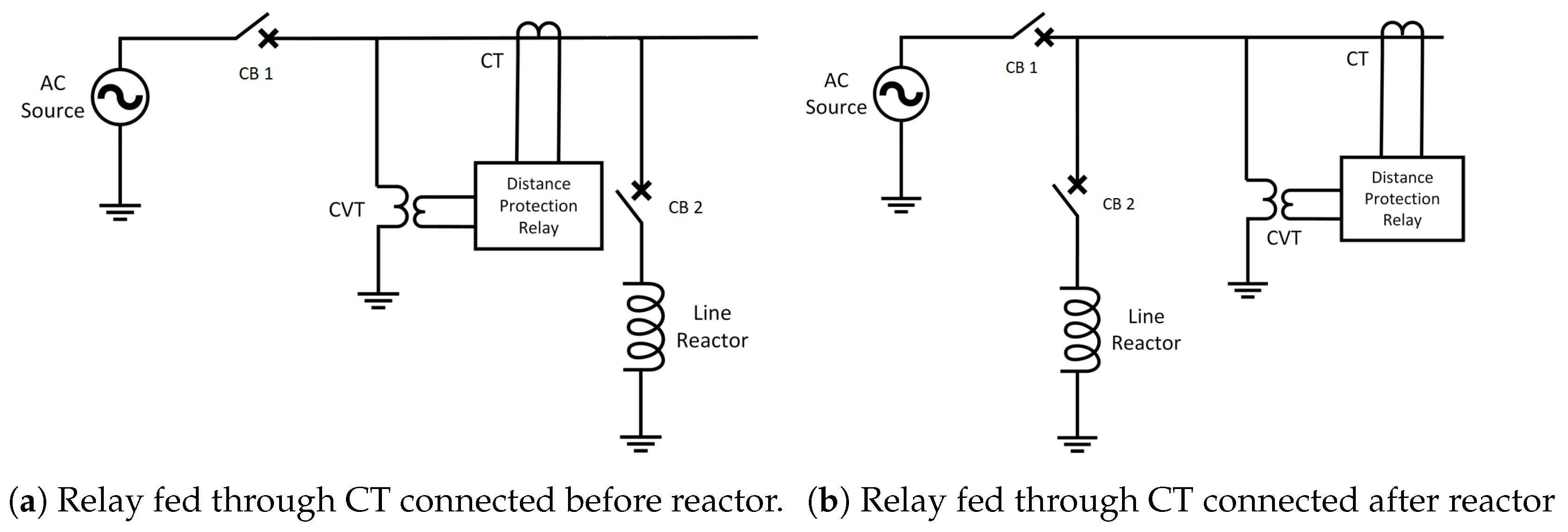
3.2.1. HIL Validation of Fault Locator Accuracy without Line Reactor Current in Distance Protection Scheme

In this HIL study, a transmission line with actual parameters connected between two 400 kV substations was simulated in a RTDSTM RTSM as shown in Figure 3 to study the impact of the non-subtraction of a line reactor current on a fault locator function accuracy in a distance relay, while using the IEC 61850 Process Bus based Full Digital substation implementation in POWERGRID India.
To carry out the HIL study, a protection IED used at POWERGRID substations was interfaced with the RTSM and associated with one end of the modeled line. In order to visualize the impact of reactor current, two cases were studied. Figure 4 shows the position of the current transformer (CT) connection for both cases. In the first case, the current to the IED was fed from the CT connected between the source and reactor as shown in Figure 4a (reactor current included) and in the second case the IED was fed through the current from the CT connected towards the line, after the line reactor (reactor’s current excluded) as shown in Figure 4b.
Both cases were studied for different types of faults and fault locations along the line and compared to determine the impact of reactor current on fault location determination. Table 2 shows the results of the fault locator performance for both scenarios in case of a line-to-ground fault at different fault positions.

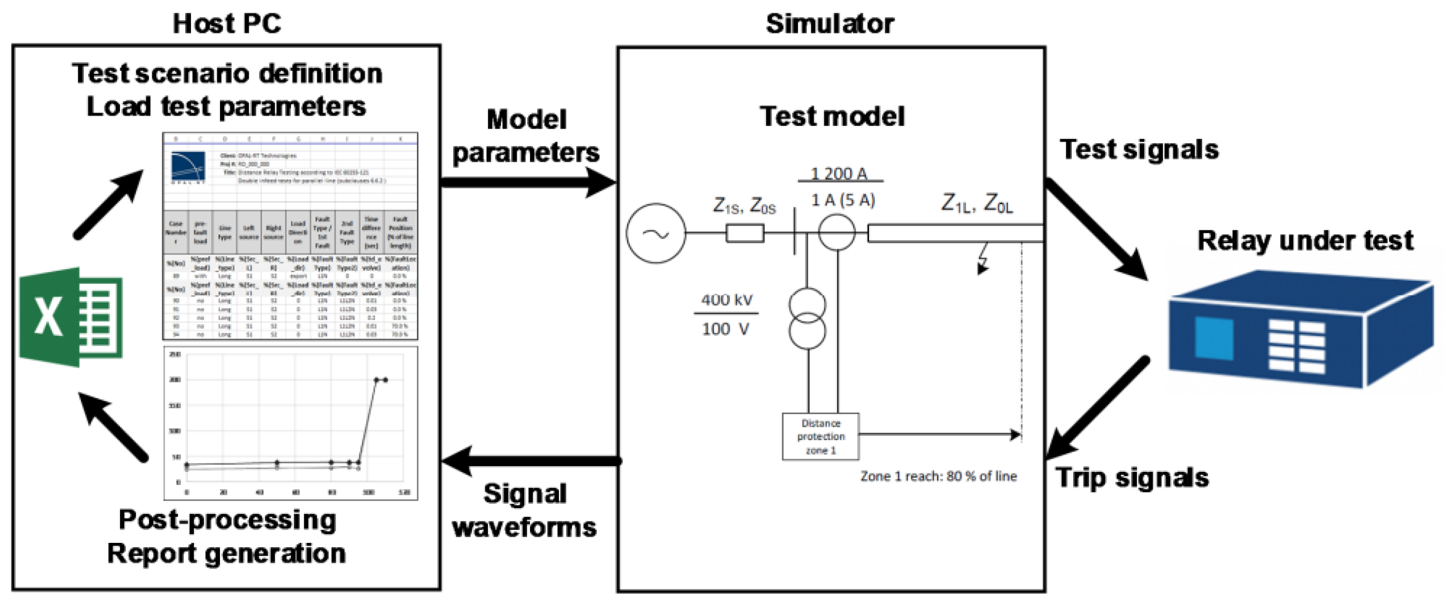
3.2.2. Distance Protection Relay Type Testing Framework

The IEC 60255-121 standard specifies the minimum requirements for functional and performance evaluation of distance protection functions. It defines the tests to be performed in order to assess the relay characteristics such as operate time, transient overreach, phase selection, etc. In contrast to standard relay test sets, using a RTSM allows closed-loop testing of relays by simulating the power system, generating the test signals, and recording the resulting waveforms. The authors in [26] presented this concept and developed a framework to automate these tests. Figure 5 presents the workflow of the proposed HIL testbed. First, test scenarios and their respective parameters were defined and fixed. A power system RTS is created and interfaced with the relay under test. Low-level signals representing voltage and current are sent to the relay and resulting trip signals and any required simulated signal are recorded for post-processing and analysis. These test results are exported, relay performance is assessed, and a report is generated. This process is repeated automatically for every test defined in the spreadsheet.

3.2.3. Adaptive Protection with HIL

The use of RTS to analyze and simulate power systems in both the steady state and faulted states provides valuable insight to the protection coordination of the power system. With the use of Analog and Digital I/Os, communication protocols (C37.118, GOOSE, and IEC 61850 Sample Values), and protection relays, an adaptive protection platform can be realized. Adaptive protection is needed when the power system has bi-directional power flows, usually from some type of DER source, that conventional protection cannot coordinate. The RTS adaptive protection platform allows designers and test engineers to evaluate and validate new equipment and methodologies in a realistic scenario [20]. In [21], an adaptive protection scheme that overcomes the challenges of the dual overcurrent relays (DOCR) in a power system with PV is proposed. Data are communicated about the PV plant to update the trip settings of the DOCR improving the protection selectivity and reliability.

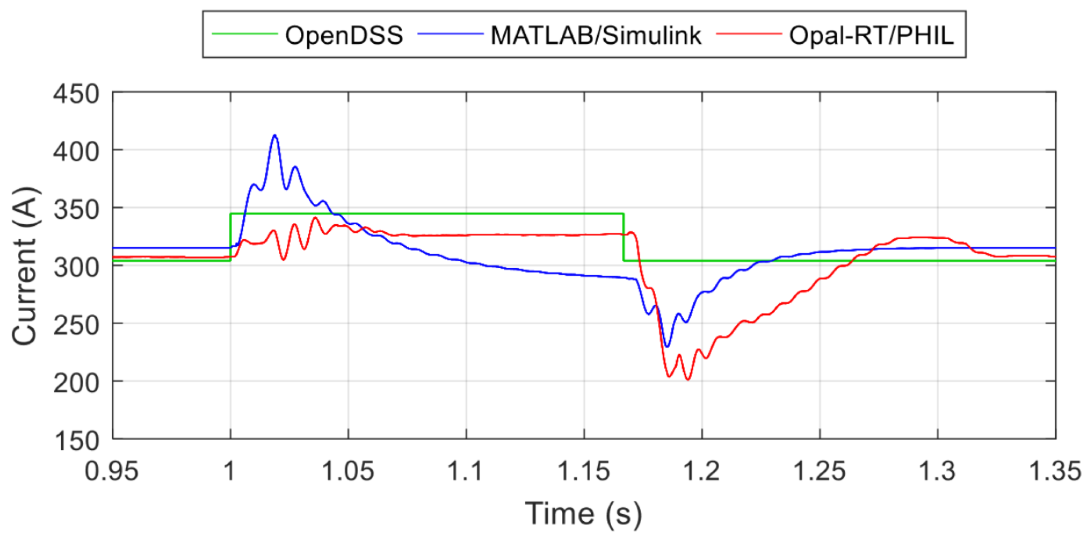
3.2.4. Fault Modeling and Validation Between Simulation Tools

When simulating distribution systems with high penetrations of DER, protection studies with short-circuit analysis and phasor analysis in the frequency domain are possible using quasi-static time-series simulation tools [24]. The computational time is fast, but no transient dynamics are included in the simulation. Therefore, some researchers have turned to MATLAB/Simulink time-domain simulations of the fault analysis, so protection studies can be performed at a much higher resolution and include transients. In certain situations the DER dynamics, switching transients, and output filter capacitor discharge behaviors are important to capture. In those cases PHIL simulations with physical DER can further improve the fidelity of the analysis.
In [25], PHIL tests were performed by connecting the physical PV inverter to a 15-bus distribution system with 2 other simulated PV systems, emulated using a three-phase dq design. Faults were simulated at locations closest to the substation, furthest from the substation, and at the PHIL-interfaced PV inverter). This work demonstrated the difference in fault currents using OpenDSS quasi-static time-series simulations, RT MATLAB/Simulink simulations, and a PHIL approach. The cases with PV that show the largest effects on the system are selected. OpenDSS provides steady-state results, whereas MATLAB/Simulink and the RT PHIL Simulation capture fault dynamics. The improvement in fidelity from the PHIL PV inverter is because it includes inductive and capacitive values that are not emulated in the dq PV inverter model and that are nonexistent in the OpenDSS PV inverters. Figure 6 shows the RMS PV inverter current when a 3 phase fault is applied at near the substation. Based on the modeling approach, the PV inverter phase A current varies. For OpenDSS, there is no instantaneous response available for the PV inverter. MATLAB/Simulink captures those transients, but interfacing the physical PV inverter provides an additional improvement in the model fidelity because it includes the output filter of the DER.

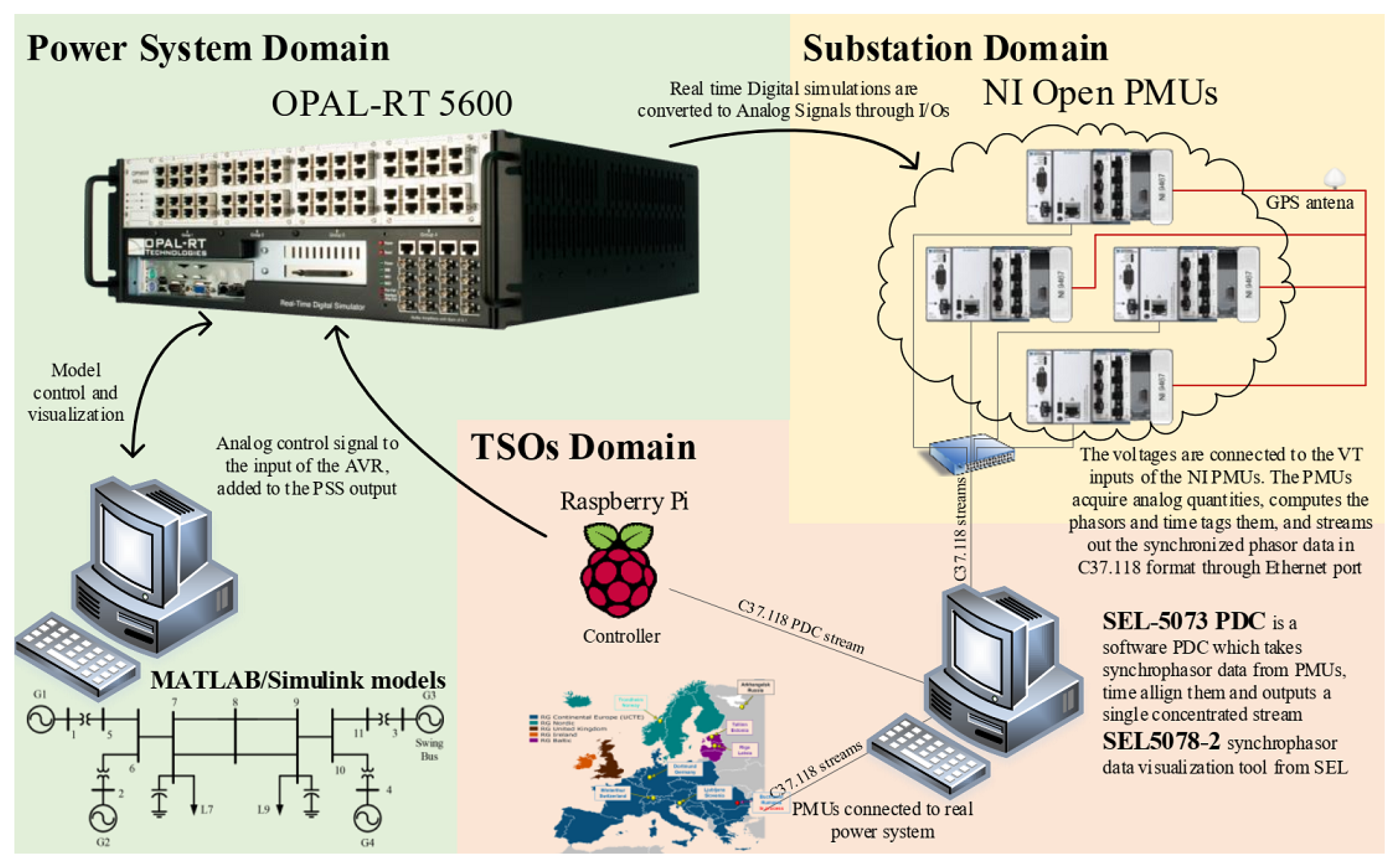
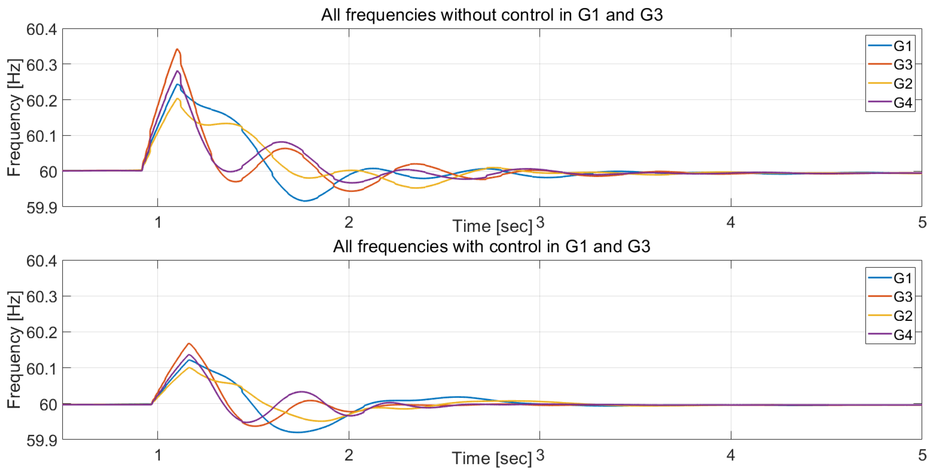
3.2.5. Wide Area Controller HIL Testing for Power Systems Oscillation Damping

In this work, different algorithms were investigated for dampening oscillations on a well-known benchmark Kundur system [31]. Controller behavior was studied by closing the loop between PMUs and an OPAL-RT RTSM. The setup is as shown in Figure 7. The Simscape Power Systems toolbox of MATLAB was used to model the two-area Kundur model in the OPAL-RT RTSM, with 4-th order model generator equipped with a simple exciter model for transient stability studies. The analog output channels were assigned to the model voltage measurements of generators 1 and 3 and connected to two NITM Open PMUs. The Raspberry PiTM devices communicate with the PMUs with a Phasor Data Concentrator (PDC), to reproduce a realistic communication loop. In the Raspberry Pi, a conventional PI controller was implemented as the complement of the PSS of Generators 1 and 3. This control was translated in voltage and assigned to the analog output of the Raspberry Pi. This controller signal is added to the PSS output and directly connected to the input of the automatic voltage regulator. The results obtained following a 3 phase short circuit are depicted in Figure 8. The implemented wide area controller improves the power system behavior as expected during the test. A detailed paper is expected to be published with application of more advanced control algorithm applying ZHAW dynamic power system technique [30] soon.

4. HIL Testing of Smart Grid/Microgrid Controllers, Energy Management Systems, and Power Electronic Converters

4.1. Introduction

Microgrids, defined as small-scale power systems consisting of load and distributed generators, are considered as an essential part of the future grid. Testing and development of MGs require detailed modeling of various components that operate over a wide range of time constants from hours (for distributed generation dispatch) to milliseconds (for accurate representation of stability and protection related phenomena). HIL testing provides these capabilities while greatly reducing the complexities of traditional test methods. By reducing the risk, cost, and total time required to test complex embedded systems, HIL systems have been used to study many MGs around the world. This section condenses the SIRFN ALTM experiences:
  • Microgrid prototyping and validation: Testing AC, DC, and Hybrid MGs requires a wide variety of techniques and methodologies including: benchmarks and prototyping platforms [32,33,34,35], testing chains and procedures for centralized and decentralized controllers [36,37,38,39,40,41], and rapid control prototyping (RCP) for a quick development of new control strategies in a real hardware environments [42,43,44].
  • Microgrid control strategies: Advanced testing methods are helpful in the establishment of the control strategies for loads and generators, reconfiguration equipment, and isolation and re-synchronization actions [28].
  • Development of inverter and power electronics functions: DER functions and device interoperability support large, traditional power systems and microgrids alike. These technologies can be evaluated prior to implementation using CHIL and RT simulation techniques [45,46,47,48,49,50,51,52]. The same testing approach can be used for large-scale power electronics integration studies [53,54].

4.2. Reported Experiences and Activities from SIRFN ALTM Members

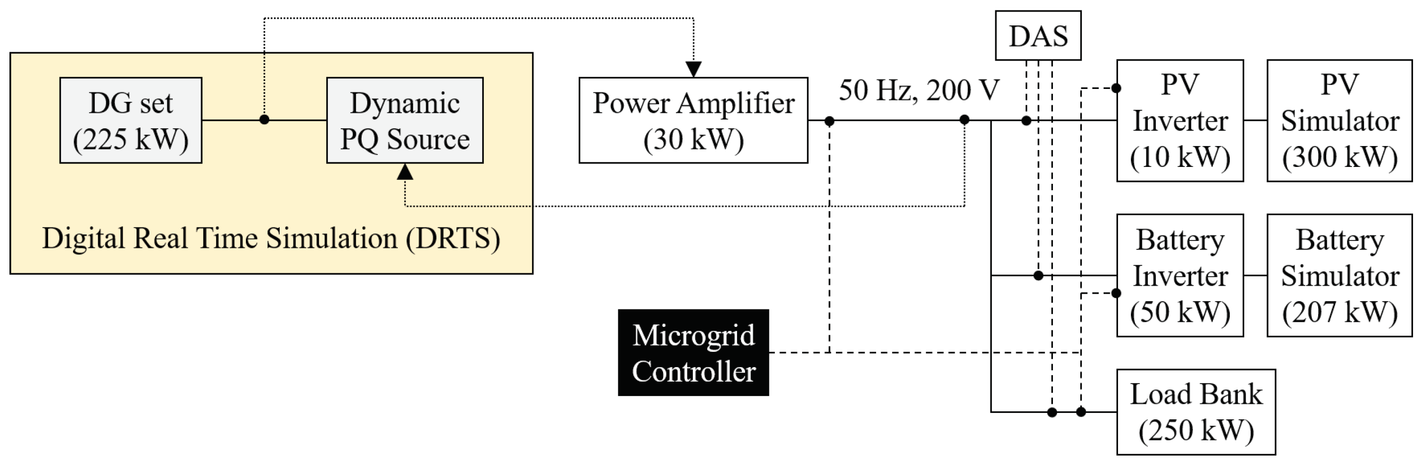
4.2.1. Integrated PHIL and Laboratory Testing for Microgrid Controller

A test setup with a physical microgrid controller (MGC), multiple microgrid components, a Data Aquisition System (DAS), and the RTSM shown in Figure 9 can be constructed by integrating PHIL technologies with a lab testing approach [33,34]. This is useful for evaluating several functions included in the MGC, which manage DER and support the operations typically reserved for diesel generators. The controller was tested in the PHIL configuration with a remote island MG. The RTSM and PA were used to emulate the diesel genset, which was not present in the lab. Device power ratings were scaled with the feedback current and voltage values to the RTSM to represent the physical system. In this PHIL setup, the MGC was interconnected to the communication systems and tested as a blackbox. In other words, the lab tests were performed without the need to know the internal design of the controller. Furthermore, testing with real hardware equipment increases the fidelity of the test results while RTS adds microgrid asset diversity. Such validation is crucial to successful on-site deployments on commissioning and site acceptance tests.
The test demonstrated that, after including in the testbed the MGC as a blackbox, it was able to stabilize the MG frequency providing set-points to the PV and Battery inverters, proving the capability of the laboratory setup to perform PHIL and laboratory testing for MGC.

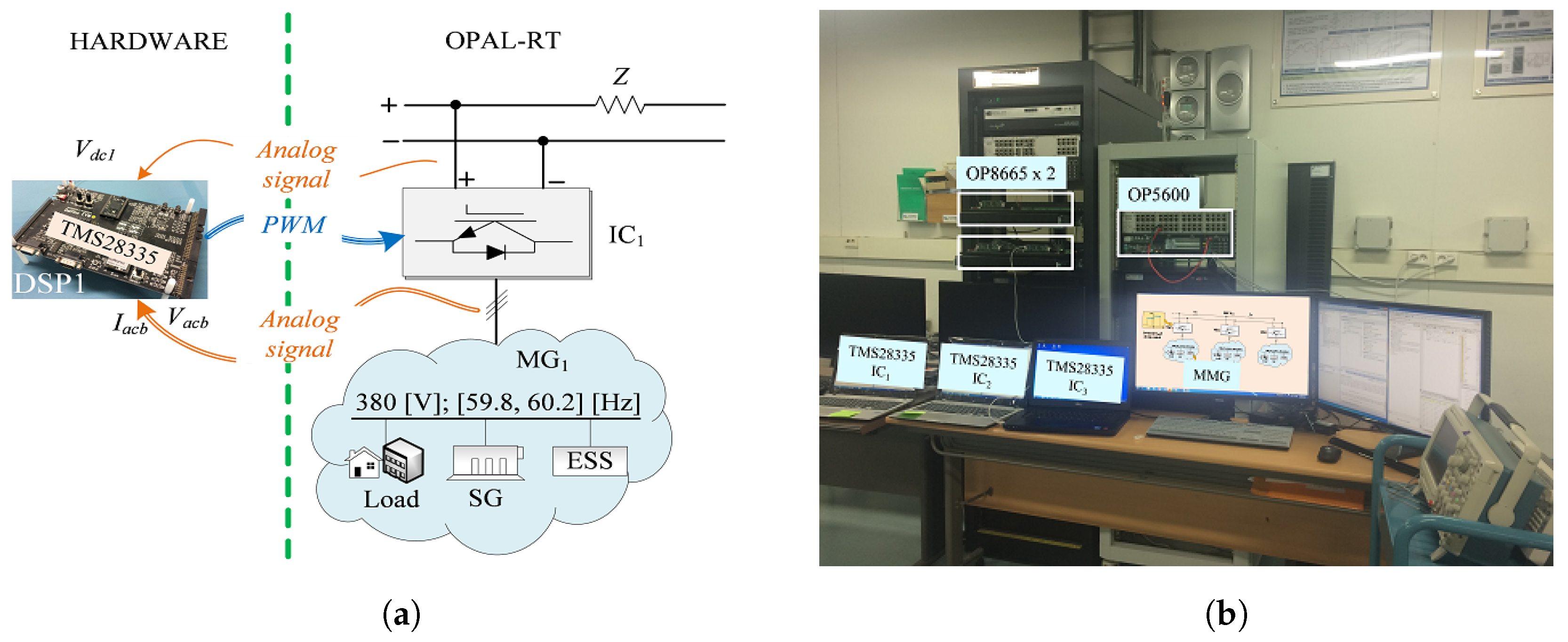
4.2.2. Development of a Droop Frequency Control of Stand-Alone Multi-Microgrid System with HIL

To operate multiple MGs with different frequencies, a framework of the stand-alone multi-microgrid (MMG) system was proposed in [43]. In the proposed MMG system, each MG connects to the common DC line through an AC/DC interlinking converter as shown in Figure 10.
An HIL system was used to validate the performance of the proposed controller. The RT digital simulator (OP5600) was used to emulate the MMG system instead of the physical plant. The proposed control algorithm implemented in a digital signal processor (DSP) can be tested easily with OP5600.
The signal exchange between DSP controller and OP5600 for M G 1 of MMG system is shown in Figure 11a. DSP controller receives the analog signal (voltage, current, and dc link voltage) from OP5600. Then, the pulse width modulated (PWM) signals generated by a DSP controller are sent to the IC1 in OP5600. The overall HIL system for the MMG system is shown in Figure 11b.

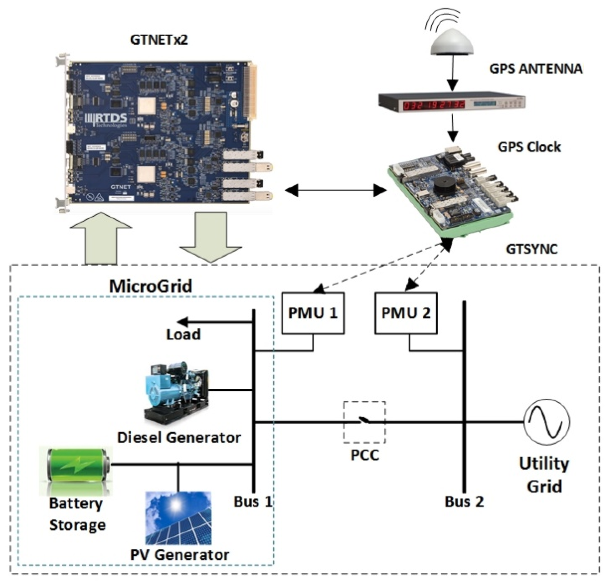
4.2.3. Microgrid Re-Synchronization with PMU Measurements

In this HIL simulation, PMU measurements were used to re-synchronize an MG with the utility grid. Use of HIL for this test case is beneficial since it involves potentially dangerous events leading to MG islanding and re-connection to an utility grid that may cause large power swings. Furthermore, co-simulation of power and communication exchanges with RTSM enables testing of the developed resynchronization techniques within the same test setup. The simulation of PMUs is carried out in the RTDS RTSM using a dedicated processing card, known as GTNET PMU card, which interfaces the RTSM with external equipment over a LAN connection using various standard protocols. For the test system used in this experiment, GTNET-PMU8 component protocol is selected in the RSCAD library. This component can emulate up to 8 PMUs that communicate with IEEE Std C37.118.2 protocol. The GTNET-PMU8 component is shown in Figure 12. For synchronizing, GTNETx2 uses a Global Positioning system (GPS) clock to provide the absolute time signal reference to the RTSM through a GTSYNC card where the phase of the signals computed in the RTSM will shift relative to the signals of external equipment. Each PMU takes 6 inputs of voltages and currents values for each phase of a 3-phase bus. The MG synchronization can occur either through active and passive MG synchronization. In active synchronization, integrated control mechanism is used to match voltage, phase angle, and frequency of the islanded system to the grid. This approach requires special infrastructure like dedicated communication facilities which involve complex controlling techniques mostly applied for inverter-based systems with high capital costs. In passive synchronization, both sides of the connection are monitored to ensure that the voltages, frequencies, and phases are within tolerance before closing the contactor.

4.2.4. Distributed Coordination Control in Hybrid AC/DC Microgrid with RCP

The study in [44] presents the MG shown in the Figure 13, consisting of an AC and DC microgrid, connected with an interlinking converter. The interlinking converter in a hybrid AC/DC MG system plays an important role of maintaining power sharing between AC and DC MG systems. The proposed coordination control strategy not only regulates accurate reactive power and DC current sharing among distributed generation in AC and DC MGs but also maintains power sharing among two MGs and restores the AC frequency and DC voltage to their nominal values. To verify the feasibility and the effectiveness of the proposed control strategies, an RCP system was designed as depicted in Figure 13.
Two OP4510 RTSMs were used to control distributed generation units and interlinking converter. The measured voltages and currents from PT and CT were sent to OP4510s. The pulse width modulated signals generated by the controllers in OP4510s were sent to distributed generation units and interlinking converter. Detailed structure of the configuration of the tested system and exchanged signals between OP4510s and real hardware system can be found in [44].

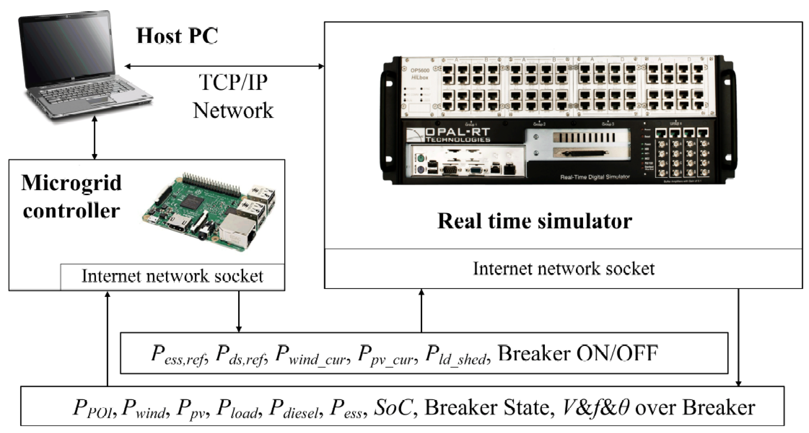
4.2.5. Design and Validation of a Rule-Based Microgrid Controller

Since most MGs contain a limited number of assets, simple rule-based dispatch is sufficient for operation. The authors in [37] present the design and validation of a rule-based MGC. The controller topology is centralized in nature, i.e., all the measurements, instrumentation, and any requests from the utility (such as islanding) is communicated to the MGC which sends out the dispatch set-points and other control signals to all the assets. Validation of the controller was performed using an HIL testbed as shown in Figure 14. The communication between the controller and the assets was achieved using IEC 61850 GOOSE messages.

4.2.6. Decentralized Microgrid Control Systems

Several decentralized MG control systems were proposed and tested using HIL testbeds. A multi-agent based control system with simulated agents in an RTSM and implemented agents on Raspberry PiTM as edge devices was presented [38]. The work presented focuses on the handling of unplanned islanding events by the use of consensus-based algorithms between several agents or a multi-agent system. A similar approach was adopted in [39,40] with the proposed resilient information architecture platform for the smart grid (RIAPS). The control system uses Beaglebone Black Boards as edge devices to implement the decentralized control functionality.

4.2.7. Microgrid Controller Development with an Advanced Testing Chain Methodology

The development of a centralized MGC with the advanced testing chain methodology [55] was based on the work in [36]. The MGC takes on coordinating tasks in the microgrid to ensure the safe operation of the components and the longest possible supply to the connected loads. MGC functions include (a) initiation, (b) coordination and monitoring of the reconstruction of the MG after major disruptions, (c) energy management in stand-alone/island operation, (d) re-synchronization, and (e) connection to the higher-level network or to another MG. In addition, all relevant measurement values and operating parameters are saved in the MGC in a second resolution for the purpose of subsequent system monitoring. For operation, a graphical user interface was created, which shows an overview of the most important operating parameters and enables the input of user commands. The operation of the MGC has been tested in pure simulation to validate the general behavior and functionality. After that, the MGC was implemented in a real-time target, in this case, a Programmable Logic Controller (PLC) Bachmann MX220. The PLC was connected to the MG model running in a OPAL-RT OP5600 RTSM through a communication interface with a MODBUS protocol. To perform a PHIL experiment, simulated components where exchanged for real devices. The PLC manages parts of the simulated MG and sends set-points to a real battery inverter, which is connected to the RTSM via an AMETEKTM RS90 amplifier. The development process of the MGC can be seen in the Figure 15.

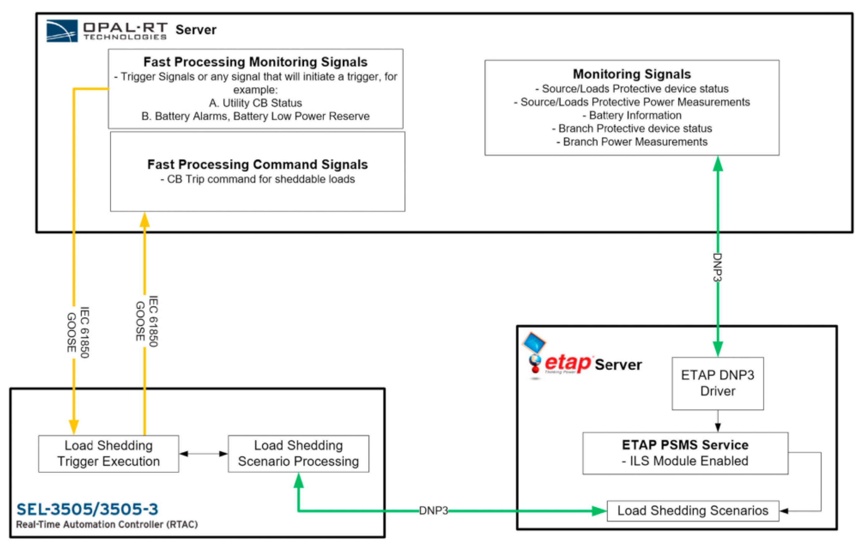
4.2.8. Generic Microgrid Controller Development, Testing, and Validation

In order to facilitate the deployment of MGs, substantial efforts have been made in recent years to standardize MGC specifications. IEEE Std. 2030.7 and 2030.8 [56] cover various functions common to MGs, regardless of their topology and configuration, as well as test procedures. As a co-chair of the IEEE 2030.7 working group, the University of California Irvine (UCI) Advanced Power and Energy Program defined specifications and developed a generic MGC that can be adapted to various MG topologies [41].
A CHIL testbed, as shown in Figure 16, was used in order to test and validate the MGC for two MG systems: the 20 MW-class UCI MG and the 10 MW-class UCI Medical Center MG. Detailed EMT models of these two MG systems, including their loads, lines, transformers, circuit breakers, and DER, were developed using Simulink and simulated on an OPAL-RT RTSM. The MGC was implemented on a platform provided by ETAPTM and time critical MGC functions were transferred to a Schweitzer Engineering Laboratories RT Automation Controllers (SEL RTACs) in order to emulate a field-deployed load controller. Monitored values from the simulated MG models are sent to the MGC using IEC 61850 GOOSE/DNP3 and resulting commands and setpoints from the dispatch functions and load shedding schemes were sent back to the simulation. Testing the MGC using HIL allowed identification of the MGs operational limits for a continuous operation and safe transition to islanded mode. An islanding of the MG was then conducted to further validate the MGC specifications and corroborate the CHIL test results. The UCI MG was successfully islanded for 75 minutes during which various load changes were applied and seamlessly reconnected to the utility grid.

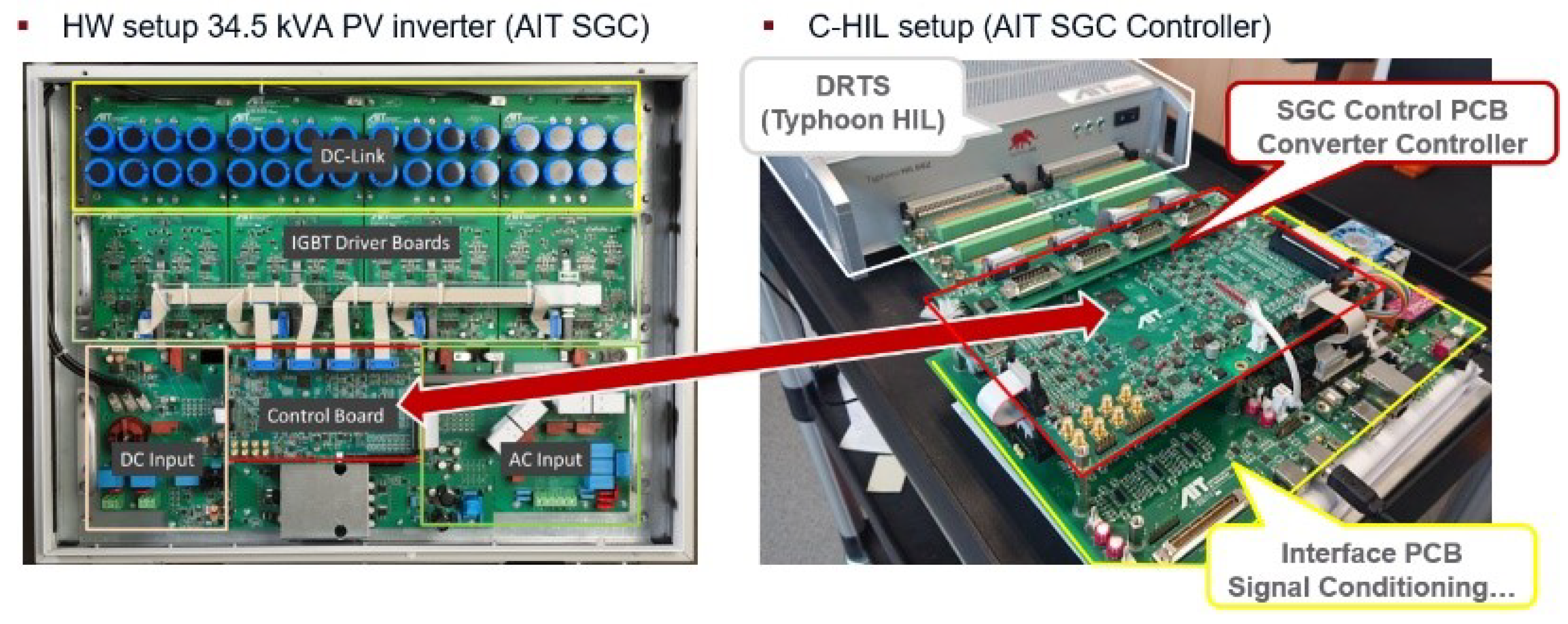
4.2.9. CHIL for Grid-Support Functions of Inverters

Advancements in CHIL technologies are enabling power electronics control systems to be accurately modeled with low-power benchtop equipment. This accelerates the design cycle by providing quick results with pre-deployment control and communications code. For instance, the Austrian Institute of Technology (AIT), in collaboration with Typhoon HIL Inc. and Sandia National Laboratories, evaluated a prototype DER controller and interoperability SunSpec Modbus interface before implementing the technology in a physical converter design [45]. By evaluating the equipment in the CHIL, software bugs could be quickly corrected in a low-consequence environment before moving to the next stage of the converter design. The AIT Smart Grid Converter (ASGC) was also evaluated against multiple North American interconnection standards, including Underwriters Laboratories (UL) 1741 and IEEE 1547-2018 [46,47], before having physical hardware to evaluate. This gave the team confidence that the equipment would perform appropriately with costly hardware. Later, the fully-built physical converter was found to have similar characteristics to the CHIL simulations for active power curtailment, frequency-watt, volt-watt, and under-voltage ride-through experiments [48,49].

4.2.10. PHIL Smart Inverter Testing with Megawatt Scale Grid Simulator

Impact assessment testing by using PHIL technologies are introduced to confirm capabilities of smart inverter functions. National Institute of Advanced Industrial Science and Technology (AIST) in collaboration with a Japanese utility and manufacturer evaluated a 500 kVA PV smart inverter at global scale smart system research facility at Fukushima Renewable Energy Institute, AIST (FREA-G). FREA-G is one of the largest power electronics testing facility with 5 MVA grid simulator and 3.3 MVA bi-directional DC source. AIST also have a one tenth scale DER testing laboratory and a design of FREA-G is based on same set up of DER testing laboratory [35]. A testing configuration is shown in Figure 17.
In this case, a RTDS/NovaCore RTSM simulates a testing power system which is shown in Figure 18a. A simulated instantaneous voltage at the point of interconnection of the PV system is sent to grid simulator and amplified to emulate a voltage of DuT. Measured current and/or voltage between the grid simulator and DuT is fed back to the RTSM to introduce behavior of DuT for power system simulation. Two test cases have been conducted with this setup. The first test case is volt-var function with low voltage ride through condition shown in Figure 18a. The second test case is a frequency-watt function with load shedding event shown in Figure 18b. The result was compared with Controller HIL (CHIL) testing to conclude the PHIL setup has the potential for assessing the impact of smart inverter functions at a large-scale. Preliminary results from a battery energy storage system can be found in [57].

4.2.11. CHIL for Validation of Unintentional Islanding

AIT developed a CHIL based testbed for unintentional islanding (UI) schemes to assess the risk-of-islanding with large shares of inverter-based DER in a project by EPRI collaborating with public utilities, inverter industry, the NY State, and Sandia [50,51].
For the CHIL UI validation testbed, a set of generic, non-proprietary UI schemes, developed in an earlier project sponsored by EPRI [52], were implemented into its Smart Grid Converter controller (SGC): (a) Sandia Frequency Shift (SFS), including Q-F-function, (b) Quasi SFS, (c) Negative sequence injection, and (d) Rate-of-Change-of-Frequency (RoCoF).
The characteristic parameters of each UI scheme can be adjusted during run-time, also allowing to enable or disable, each of the UI schemes. To enable the operation of multiple UI schemes at the same time, a special “decision-tree” concept allows a quasi-parallelization of the UI schemes. This allows to utilize the advantages of the individual schemes while reducing the need to apply “aggressive” settings to the individual parameters. Through this concept, the reliability of the UI detection can be increased and at the same time, negative effects of UI schemes on the voltage quality, grid stability, etc. can be mitigated. The CHIL setup consists of the control board taken from the AIT SGC which was connected to the RTSM (Typhoon HIL 602). Using this setup, the AIT SGC controller can be operated under the same full range of operating conditions as for the physical laboratory tests, as shown in Figure 19.
The model running on the RTSM includes SGC’s power train, a PV array, and a power grid model, represented by an adjustable RLC circuit for the simulation of the local system load. Using the model, a wide range of tests were performed to investigate and validate the response of the UI schemes, the sensitivity of their parameter settings as well as the impact of advanced grid support functions and ride-through capabilities. For each condition, the impact of key control parameters on the effectiveness of the UI schemes, i.e., accurately and reliably detect the islands and trip the inverter, was assessed.
The work successfully demonstrated the benefits of the CHIL testbed to assess the UI schemes implemented in inverter-based DER. As part of the project [50], studies were performed to investigate the sensitivity of control parameters on the overall performance of studied UI schemes, the resulting run-on-time and other characteristics was assessed. In addition, the impact of advanced grid support functions on the capability to reliably detect islanded conditions was assessed.

5. Co-Simulation and RTS Integration

5.1. Introduction

Smart grid co-simulations are growing in popularity. The need for integration of new technologies in the power systems is challenging and has driven the industry and scientific community to develop their own tools and software. Co-simulation plays a big role in these assessment approaches as showed in [58]. However, one specific problem with co-simulation is coupling multiple simulation platforms. The majority of them involve a large number of distributed physical devices controlled by various software components and advanced algorithms, with a common interface based in communication technologies.
This section contains SIRFN ALTM experiences including integration of RTSM to co-simulation platforms [59,60], network emulators, and cyber–physical systems in co-simulation and HIL [61,62,63], development of tools with enhanced cybersecurity features for co-simulation and HIL experiments [64,65], and integration via co-simulation of electrical vehicles charging station interfaces [66].

5.2. Reported Experiences and Activities from SIRFN ALTM Members

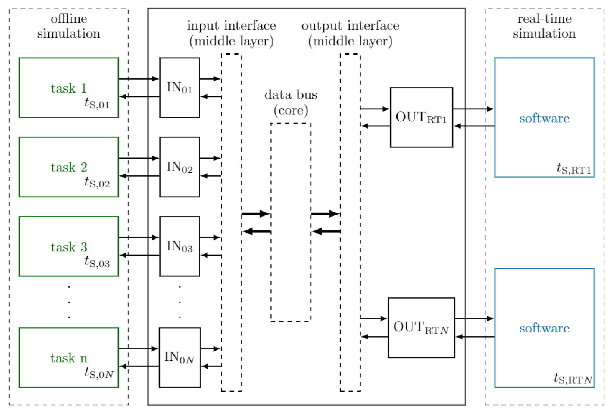
5.2.1. Asynchronous Integration of RTSM with Co-Simulation Platforms

In [59], possibilities for testing and validating advanced control strategies and smart grid applications with RTSM co-simulations are studied. It presents two approaches based on a Message Bus architecture, depicted in Figure 20, for co-simulation and rapid prototyping of networked systems:
  • Lablink: Simulation Message Bus (SMB) based Implementation
  • OpSim: Representational State Transfer (REST) based Implementation
Depending on the used approach, coupling software simulators to an RTSM will introduce latency in which improvements below the 1 ms threshold cannot be expected, and this will limit the spectrum of applicability of the co-simulation approaches for system-based testing.
A co-simulation environment developed by Fraunhofer IEE and the University of Kassel, called OpSim, was created for both RT and non-RT co-simulations of complex power systems [60]. The objective of this co-simulation platform is to make research on smart grids affected or operated by several stakeholders by interconnecting different simulation models form different software tools. The core of its platform is a REST based message bus that manages the exchange of information between clients by means of a client/proxy architecture.

5.2.2. Co-Simulation of Cyber–Physical Systems

Co-simulation of the communication network on the network emulation software (ExataCPS) along with the electric power network simulated with a RT EMT type software (HYPERSIM and RT-LAB) was created in [61]. The differentiating factor between the two proposed configurations of the co-simulation was the implementation of the communication link and the number of RTSMs involved. In one configuration the RTSM was used to run the power network simulation and the controller was connected to the simulator via a computer running the communication network emulation software, as shown in Figure 21b. The second configuration involved a single RTSM where the power network simulation and the communication network simulation were run on different cores with a virtual link between them as shown in Figure 21a. In both cases, the authors specifically showed co-simulation of a MGC communicating with the assets on a MG. The specific cyber phenomena studied was communication delay due to: cyber attack, data manipulation, and man-in-the middle attacks. Similar testbeds with physical communication connections were proposed by the authors in [62,63], with the exception that the communication system emulator used was OPNETTM. In both cases, the testbed involved the interfacing of the RTS with the monitoring and control node via a host computer running OPNET exchanging information by its System-in-the-Loop (SITL) interface. The distinct feature of such testbeds is the synchronization of the two kinds of simulations. The RTS usually runs a time-stepping simulation that is either EMT or phasor domain, whereas the network emulators are discrete event based simulators.

5.2.3. SCEPTRE: Suite of Tools Providing an ICS Co-Simulation Environment

There is an increasing desire to establish co-simulation environments that capture the characteristics of multiple domains. For smart-grid applications it is often important to model both the power system dynamics as well as communication network dynamics. To this end, many researchers have been constructing cyber–physical simulation tools. Sandia National Laboratories has developed a suite of tools called SCEPTRE (capitalized but not an acronym) that provide an industrial control system (ICS) co-simulation environment. SCEPTRE has been used in a number of projects to capture the dynamics of communications and power systems. One good example is a project that established a distribution power system simulation with large PV plant at the end of the feeder. Simulated PV inverters were created that interacted with the power system so that any changes to the controllers would be reflected in the power simulation and vice versa. An adversary-based (red team) assessment was performed for different cybersecurity defenses (segmentation, encryption, and moving target defense) in this environment and given a cybersecurity score [64,65].

5.2.4. Electrical Vehicle/Charging Station Integration Testing

AIST developed a smart electric vehicle (EV) management communication solution in accordance with IEC 61850 for the communication link between EV and charging station (CS) [66]. First, a new information model was developed to emulate CSs. Second, a model based on IEC 61850-90-8 was altered to accommodate reverse power flow by the CS model. Steps of the EV management scheme were transferred via IEC 61850 messages based on their transmission purpose and nature. Simple measurements were sent with Sampled Values (SV), event-based instructions were sent as Generic Object-Oriented Substation Event (GOOSE), and other ad-hoc information exchange is down with Manufacturing Messaging Specification (MMS)
In order to validate the standardized models and messages, an HIL test was performed with the topology shown in Figure 22. An IEC 61850 emulator was utilized to model an EV while a digital RTSM modeled the CS (and connection to the grid). In the future, the RTSM will be integrated with an optimization software to run power system simulations and centralized control algorithms.

6. Geographically Distributed HIL and RTS

6.1. Introduction

The operation and planning of power systems is continuously increasing in its complexity with the integration of innovative components, controls, and novel architecture paradigms. Accordingly, aspects of scalability and stable system dynamics must be evaluated with advanced laboratory testing methods to provide confidence in the technologies prior to deployment. The requirements for a single test bed to cope with such a diverse and large scale system are extensive; however, the RT coupling of geographically distributed test beds can overcome any such limitations that a single test site might face. This expands the realms of validation not only by incorporation of additional equipment available but more importantly brings wider experienced individuals together.
The classification of geographically distributed (GD) simulation setups is currently being undertaken within the IEEE PES Task Force on Interfacing Techniques for Simulation Tools, with the broadly identified classification reported here as:
  • Geographically distributed RTS: in this group only RTSMs at both ends are coupled together. Typically, this is used to overcome large simulation complexity that would require large RT resources that might not be available in a single test site. This has been the most common type of GD simulations reported in the literature [67,68,69,70,71].
  • Geographically distributed HIL experiments: this group involves configurations where hardware is coupled remotely to a RTS. By using this configuration, the testing of hardware equipment (controllers or power components) in a system environment when no RTS is available at the premises is made possible. The involvement of hardware in this group requires careful consideration based on the interfacing method and communications [72,73,74,75,76], as discussed in Section 2.
The main challenges arising from the implementation of GD simulation have been identified as the interfacing method and the communication medium utilized for the realization of the interface, and these are briefly discussed next.

6.1.1. Interfacing GD Simulations

The accuracy and stability of an interface algorithm utilized for the coupling of subsystems presents a challenge. The interface algorithms used for GD simulations are in practice similar to the ones used for monolithic PHIL or CHIL simulations but with significant increase in time delay (due to the geographic separation of the infrastructures), which impacts the stability of these configurations in comparison to single-site PHIL and CHIL.
The representation of the signals exchanged between the subsystems, such as instantaneous, RMS, or any transformation thereof, plays an important role in a successful implementation of a GD simulation setup. Studies to establish the appropriateness of signal representations have been widely reported, where the selection of signal representation can be concluded as a trade-off between accuracy and stability for the given application [69]. The implemented representation can also be important for allowing the compensation of time delays as the ideal place for this compensation is at the interface and the format selected can decide on the feasibility of the time delay compensation [71,77].

6.1.2. Communications

The communication over long distances between geographically separated assets is the key characteristic that differentiates monolithic HIL simulations from GD simulation. For feasibility purposes, communication generally takes place over the Internet with time delays depending on the available network infrastructure between the sites and in contrast with monolithic setups present non-deterministic time delays [78]. Latencies over the Internet between different cities have been evaluated in [69,72]. Most of the publications in the field use the User Datagram Protocol (UDP) for transmission of data due to its RT capabilities [71,74,76,79], although the use of other protocols such as Transmission Control Protocol (TCP) or RT Protocol (RTP) have also been reported [14,67,69,75]. Additionally, an orchestrator can be utilized to coordinate the protocols, time steps and also for visualization and data logging aspects.

6.2. Reported Experiences and Activities from SIRFN ALTM Members

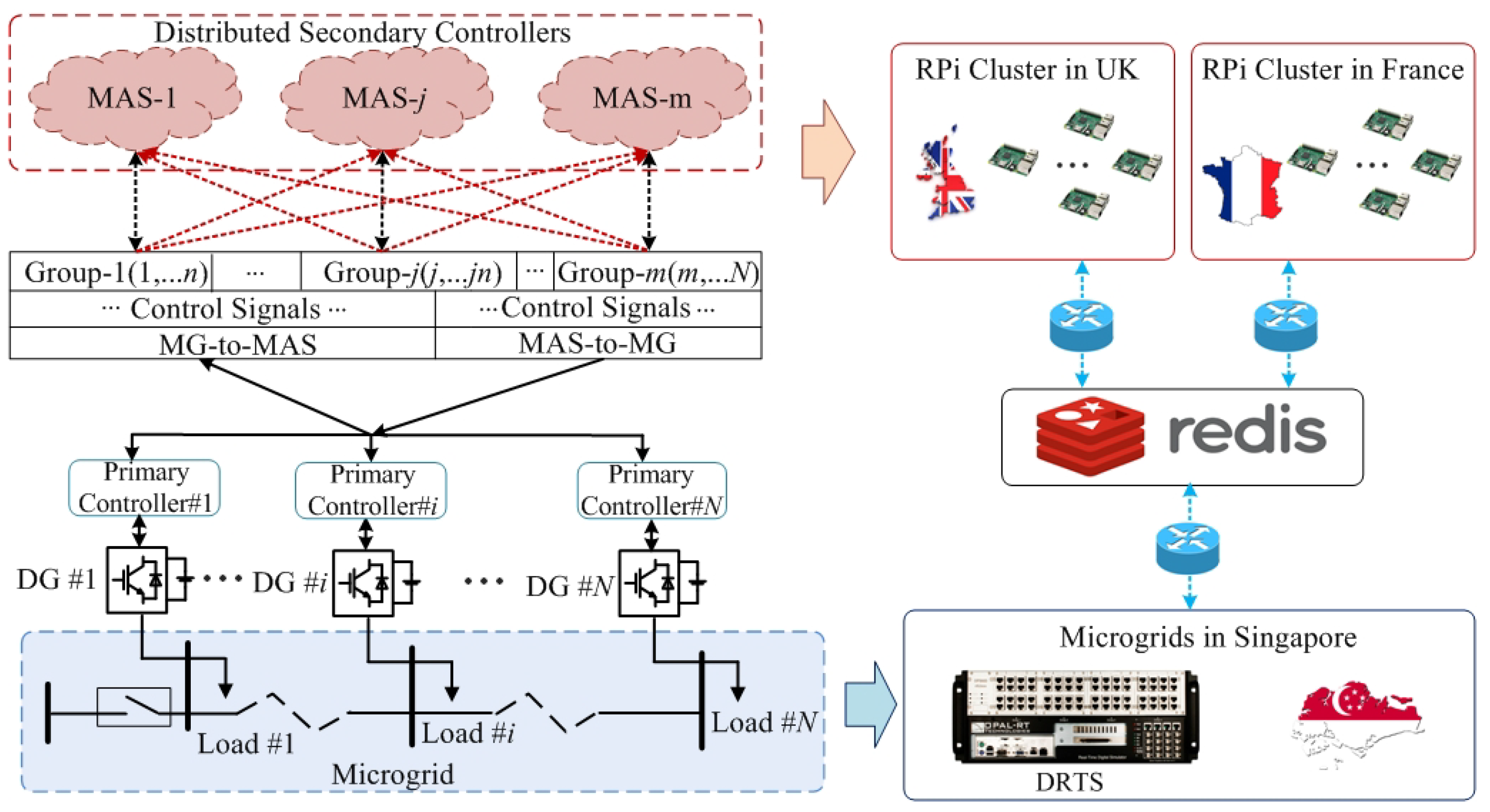
6.2.1. Geographically Distributed CHIL for Advanced Validation of a Distributed Control Algorithm

To increase the realism of the distributed control algorithm validation environment, GD simulation can be configured with the controller units geographically separated from the simulated power system (emulating the environment in which they could be deployed). An example of such configuration is presented in Figure 23, in which a distributed control for a MG is evaluated [72]. By using the GD architecture, the data exchange between the controller units as well as between the power assets and controller units can be thoroughly evaluated under a real communication network with uncertainties such as latency or packet-losses that might occur during the validation procedure. In this case, the RTS of the power system is hosted at Nanyang Technological University, Singapore, while the clusters of distributed controllers are located at University of Strathclyde, UK and University Grenoble Alpes, France. The local communication between the controllers is established by TCP/IP, for the communication with the power system UDP protocol through a cloud server service is used (Redis).

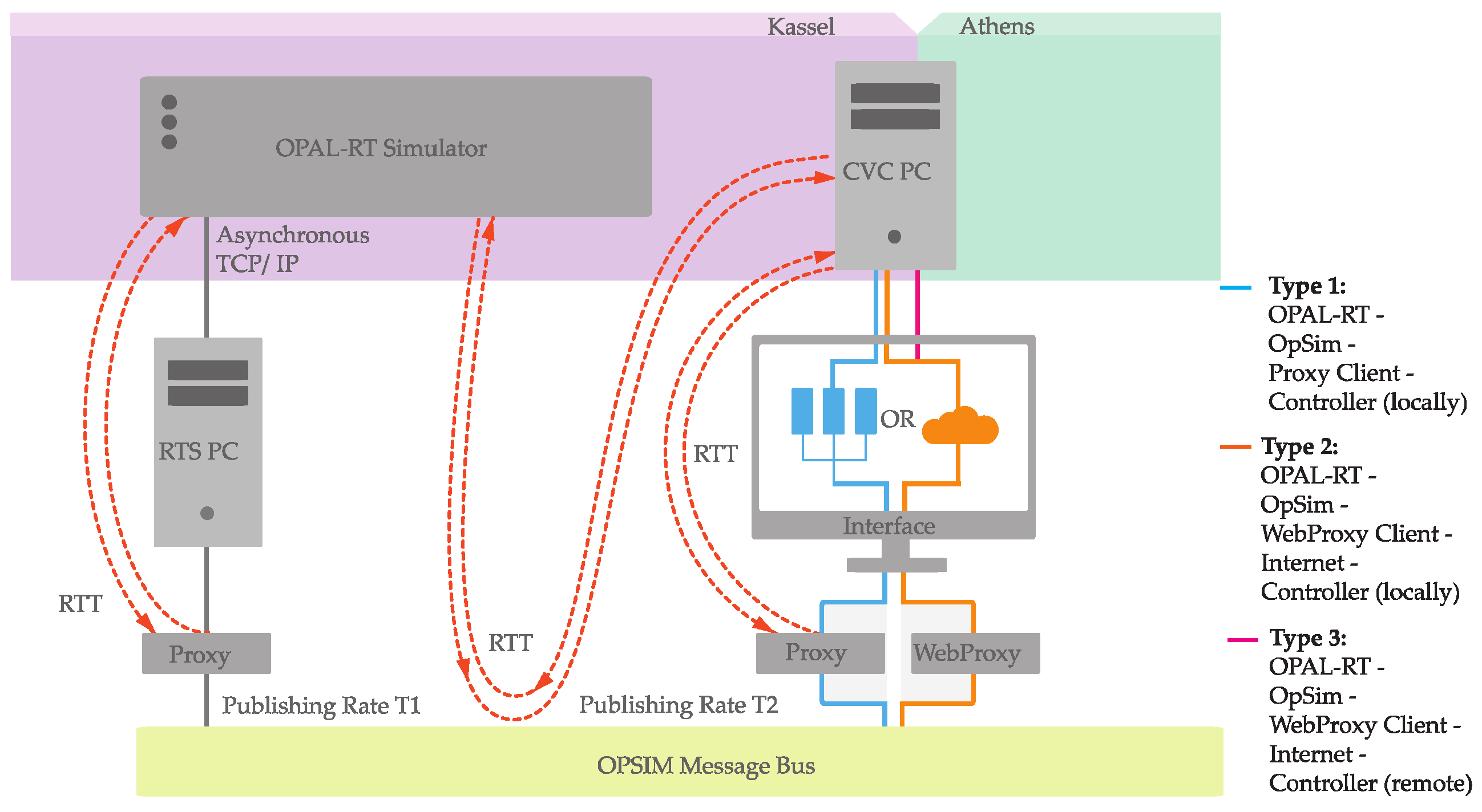
6.2.2. Delay Assessment for Geographically Distributed CHIL Experiment

The author in [75] presents a delay assessment for two GD devices (a PC with a controller and a RTSM) interfaced via a co-simulation platform. Both devices were interfaced between Germany and Greece (Kassel-Athens) through an asynchronous TCP/IP connection. The so-called co-simulation platform OpSim was used as an orchestrator as shown in Figure 24. The objective of this work was to share resources of GD research infrastructures, to assess delays and latencies of GD simulators, and to define the limits and RT capability of the OpSim platform.
This particular experiment presented the limits in latencies between OpSim and each GD simulator by measuring the Round-Trip Time (RTT). In addition, the validation of a coordinated voltage control (CVC) was made by benchmarking the GD simulation with pure simulation results from Matlab.
The results indicated that OpSim has RT capabilities to interconnect GD simulators from different research laboratories by means of asynchronous communication and to perform slow (low-bandwith) grid voltage control. Based on the user-defined values, variables, and publishing rates, estimation tools provide a way to analyze if a RT co-simulation experiment can be performed a priori.

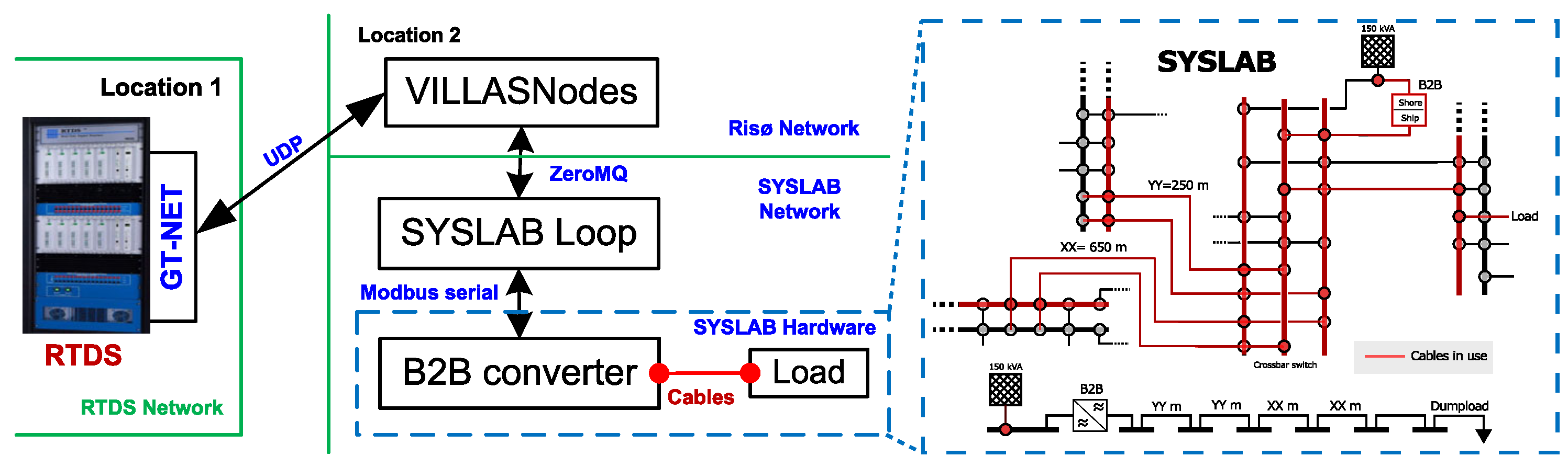
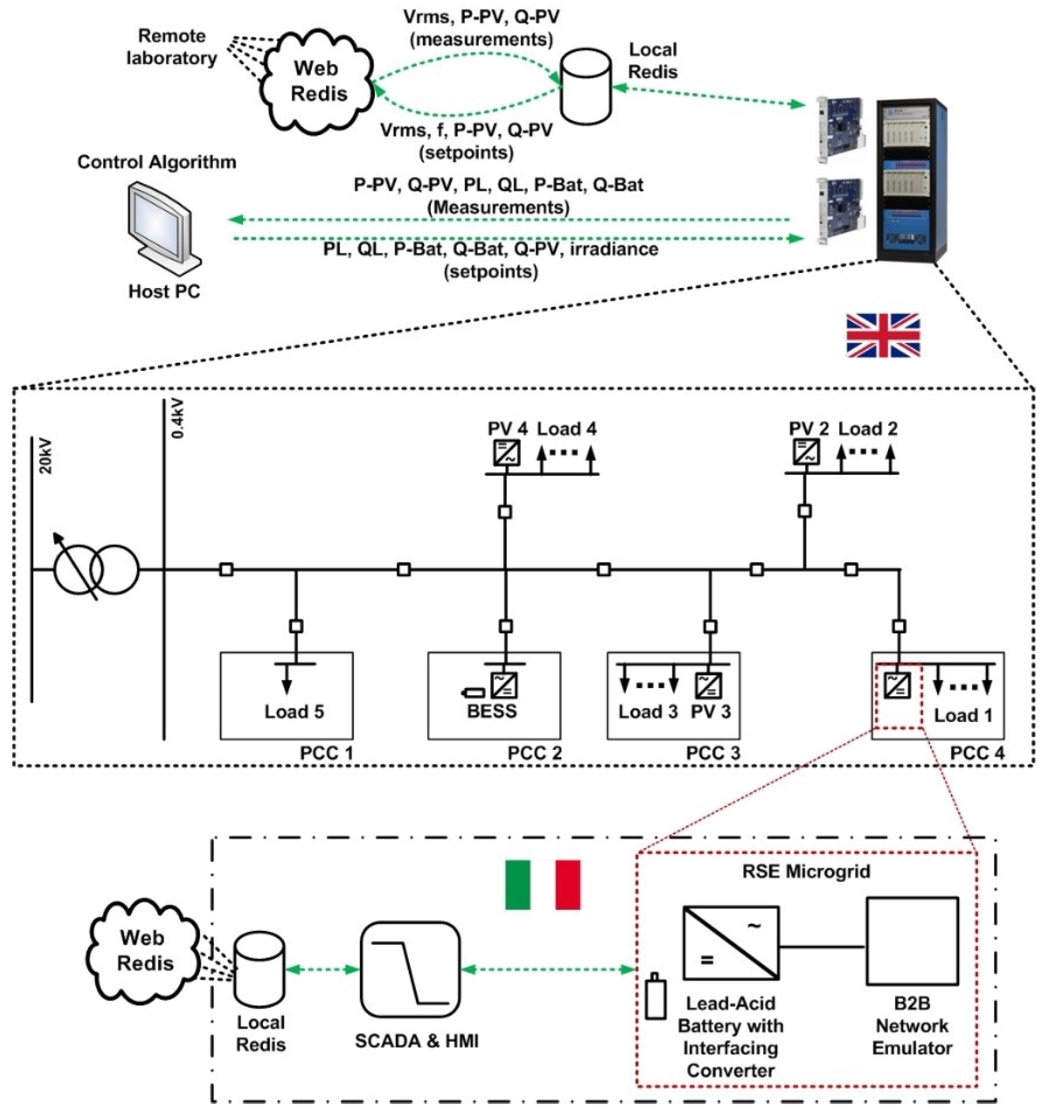
6.2.3. Geographically Distributed PHIL for Testing of a Voltage Controller

This case study investigated the feasibility of geographically remote power equipment to be incorporated for the validation of a control algorithm to enable a systems testing environment.
The GD-PHIL configuration is shown in Figure 25, where a CIGRE low voltage test network is simulated in RT at University of Strathclyde with the control algorithm under validation in a CHIL implementation. To incorporate the behaviour of a real hardware device, and to characterize its consequent impact on the performance of the control algorithm, a battery energy storage system at the premises of RSE (Italy) was interconnected at PCC4. Further details on the implementation can be found in [14,80].

6.2.4. Global RT Super Lab Demonstration

In certain situations, connecting multiple RT power simulations provides greater fidelity or realism than a monolithic simulation. For instance in the RT Super Lab demonstration, a geographically distributed RTS (GD-RTS) representing transmission-distribution co-simulation was created with different PHIL- and CHIL-interfaced equipment connected at each of the facilities. Idaho National Laboratory ran the transmission simulation and seven other laboratories located in North America and Europe ran distribution simulations that interfaced with the transmission simulation. The goal of the simulation was to see if transporting energy intercontinentally would be possible to avoid blackouts, assuming there was transmission capacity to do so [76]. The co-simulation was possible using VILLASframework, a decentralized software suite that enabled gateways to communicate using UDP, Message Queuing Telemetry Transport (MQTT), Advanced Message Queuing Protocol (AMQP), or IEC 61850.

6.3. Future Outlook

Although the concept of GD simulation has been around for over a decade, more recent advancements in the past couple of years have led to a renewed interest in their utilization. With a wide array of implementations being reported, a few research gaps still remain to be addressed, such as:
  • With a number of different interface algorithms, signal transformations, and communication protocols being reported, there is a lack of formalization or guidance available for selection in regards to application. A set of combinations need to be appraised for applications such as transient studies, dynamic studies and steady state evaluations.
  • Recognizing that the communications delays are dominated by the non-deterministic characteristic of the Internet, options such as use of dedicated bandwidth should be explored.
  • In distinction to a monolithic PHIL simulation where a DuT is connected to a RTSM, the GD simulation presents a significant challenge in determining system partitioning. The optimal approach to split a system for simulation over the GD simulation requires further assessment.
  • With the number of subsystems within one GD simulation expected to increase, where more than two research infrastructures are expected to be interconnected, a streamlined facilitation of initialization is required. A lot of work for co-simulation setups has been reported and their applicability for GD simulation needs to be explored.

7. Industrial Experiences and HIL in Standardized Testing

7.1. Introduction

Recent standards revisions have acknowledged the use of HIL as a way to test compliance. The IEEE Std. 2030.8-2018 [56] accepts testing environments ranging from fully simulated testbeds to field installed equipment. HIL testing with RTS for full or partial testing of the MG control systems is included within the accepted simulation environments. Similarly, the forthcoming IEEE Std. 1547.1 revision [81] also accepts HIL as a way to test compliance, and also demonstrates an example of performing unintentional anti-islanding test with a PHIL setup. However, the research community keeps putting efforts on development of platforms for validation according to grid codes and pre-certification of units [47,82,83,84], definition of procedures for compliance testing and acceptance tests [85,86,87,88,89], and validation of marine- and aero-electrical power systems [90,91,92,93].
Furthermore, the ongoing IEEE Standards Association Project P2004-HIL Simulation Based Testing of Electric Power Apparatus and Controls aims to provide recommended practices for using HIL as a method of testing electric apparatus and controls for standards that accept it as a testing method. In addition, the ERIGRID project outcomes include a book to be published under the name European Guide to Power System Testing: The ERIGrid Holistic Approach for Evaluating Complex Smart Grid Configurations [14] and includes the experiences and suggestions for standardization of testing and validation of cyber–physical energy systems (CPES) by the use of simulation, co-simulation, and HIL laboratory testing, which can act as a reference for researchers interested in developing standardization of HIL techniques in the future.

7.2. Reported Experiences and Activities from SIRFN ALTM Members

7.2.1. Compliance Testing of a Hybrid UPS According to JEC2433-2016

The authors in [85] used HIL testing for design and compliance testing of a hybrid UPS based on an emergency diesel generator and battery energy storage system. The hybrid UPS was tested to meet the class 2 UPS requirement from the Japanese standard on UPS, JEC2433-2016. The authors adopted the CHIL approach to evaluate the compliance of the designed controller. The CHIL testbed and all the results of the compliance can be further seen in [85].

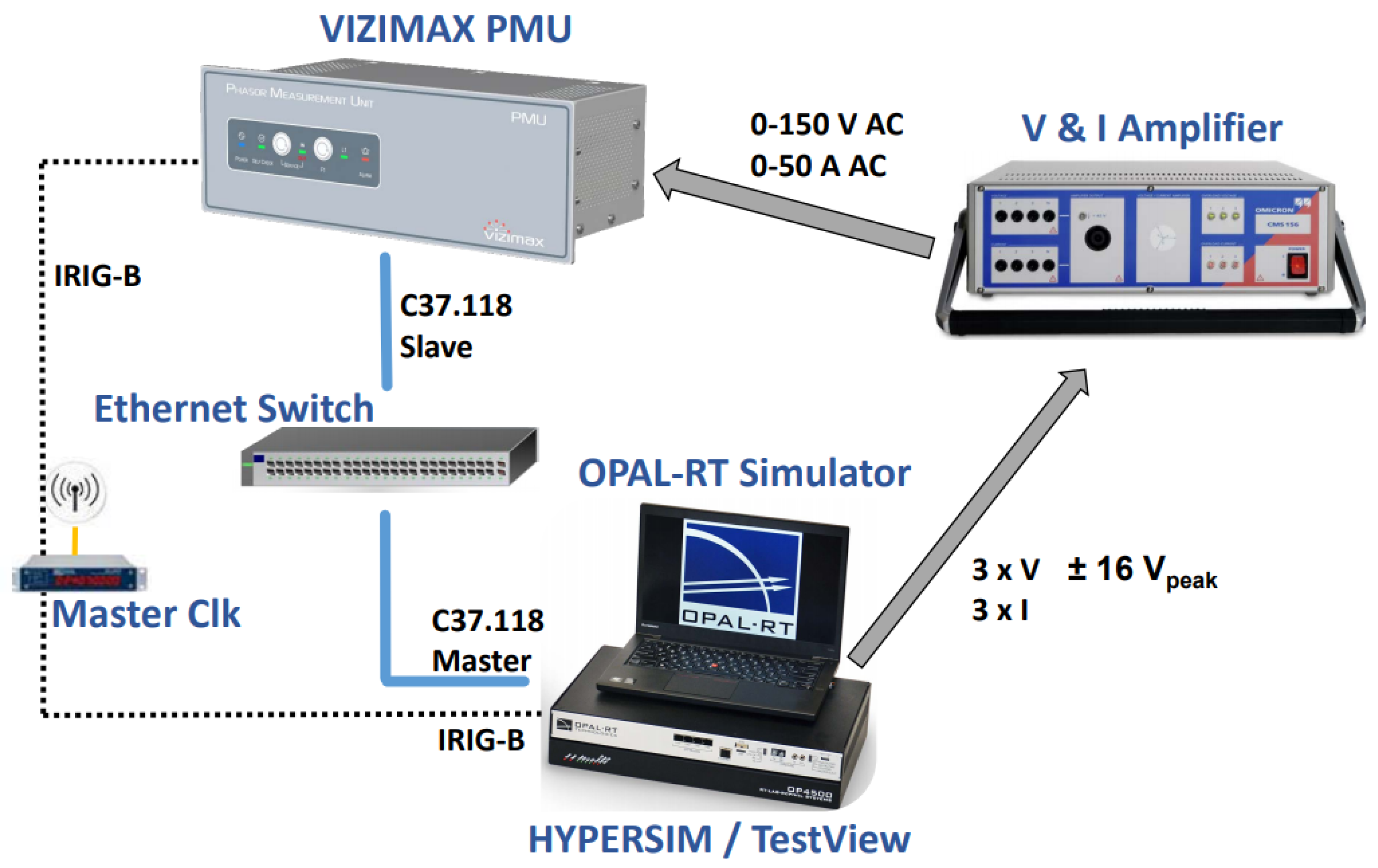
7.2.2. Development of a PMU Pre-Certification Platform

OPAL-RT and Vizimax collaborated on the development of a HIL phasor measurement unit (PMU) pre-certification platform [82]. This collaboration allowed Vizimax to successfully validate their PMU compliance with IEEE Std. C37.118.1 prior to testing at the National Institute of Standards and Technology (NIST). Furthermore, it allowed OPAL-RT to validate their test equipment performance and develop a standard compliant automated HIL PMU test platform. It was demonstrated that using HIL is a valuable method for pre-certification of monitoring, control, and protection devices with an accuracy comparable to that of calibration lab equipment. Furthermore, it provides the capability to go beyond the standard requirements. A diagram of the testbed is shown in Figure 26.

7.2.3. Factory Acceptance Tests Based on HIL Testing

Hydro Quebec has been involved in HIL testing of their AC/DC interconnected network with hybrid (analog and digital) and fully digital simulators [86,87]. The authors perform CHIL studies with a one-to-one replica of the HVDC line commutated converters controller of both terminals of the high voltage DC (HVDC) lines. The power system components including the power electronic switches, DC filters, DC transmission lines, etc. were all simulated while the controllers were actual controllers interfaced with the simulation link using I/O. Réseau de Transport d’Électricité (RTE) in France applies a similar approach for testing of static var compensators (SVC) connected to their network [88]. All the power components were simulated on the RTSM while the controllers were interfaced with the simulation via I/Os. Factory acceptance tests (FAT) based on HIL testing of a replica controller of a five terminal modular multilevel converter based HVDC project was presented in [89]. The power components were simulated on a multi-rate simulation platform using both the CPU processor and the FPGA for high fidelity simulation requirement of the application. Many other utilities adopt a similar approach for various other Flexible AC transmission and HVDC devices as well including series compensators, synchronous condensers etc.

7.2.4. System Validation Platform HIL Based Grid Code Testing Aspects of DER Inverter

Several international laboratories have collaborated for years to evaluate the grid support functions of DER devices [47,84]. For this purpose, the group uses a versatile open-source DER testing and certification platform known as Sunspec System Validation Platform (SVP) [83]. SVP automates the test procedures by executing sequences of testing logic that change the settings on the DuT, grid simulator, PV simulator, and data acquisition system using Python test scripts. The group has developed drivers for a wide range of communication interfaces, power simulation and data acquisition equipment. For CHIL tests, drivers for Typhoon HIL RTSM were implemented. The group has assessed the test procedures from different standards, i.e., UL 1741 SA [94], forthcoming IEEE 1547.1 [81], etc. and provided feedback to the standards development organizations for corrections and enhancements of the test procedures. The implementation of the test procedures from IEEE P1547.1 standard required tests with unbalanced voltage magnitudes and phases, and maintaining specific rate of change of frequency (RoCoF), which are not achievable directly in certain grid simulators when they are controlled directly through communication link from SVP. To address these issues, a RTS based signal generator was developed in OPAL-RT eMegasimTM environment. The signal generator implemented all the test requirements of AC source for IEEE P1547.1 and was easily controlled through the Python API of RT-LAB (ver. 2019.2.3). In this case the Python API supports test automation and is directly controlled from SVP. This approach has been used to collect the test results in [47] and this methodology is proven to be reliable. The UL 1741 SA and IEEE 1547.1 test scripts used in this SVP based activities are also available at Github.

7.2.5. HIL for Marine Electrical Power Systems (MEPS)

The advancements brought to power systems validation with the use of RTS and HIL methods have prompted its use in other sectors such as MEPS and aero-electrical power systems. These sectors have recently begun the integration of smart grids concepts to leverage on their advantages. However, these novel concepts need to be thoroughly assessed by the use of laboratory testing methods before their deployment [90]. Such testing methodologies have been utilized for a number of applications, such as the assessment of the impact of incorporating novel components like high power dense direct current loads and their power electronic interfaces [90,91], smart coordinated control strategies [92], and MEPS architectures [93].

8. Summary of Testing Methods and Configurations

This review takes into account various experiments and experiences in different fields of research, using different research infrastructures and devices. Below, the methods described in each subsection are cited. Table 3 condenses the hardware used in the reported activities from the SIRFN ALTM members subsections to give the reader an overview of the equipment used in HIL experiments.
Additionally, this review provides a summary of the reported literature used for each section as a fast-track to references, and is listed in the Table 4.

9. Conclusions and Future Outlook

A key to advancing the deployment of smarter, cleaner electric grids is the development and validation of technologies, protocols, standards, and systems that can function effectively in a variety of geographies and grid environments. Laboratories within the SIRFN community are actively expanding laboratory testing methods to evaluate and demonstrate new power system control, optimization, and design technologies. ALTM capabilities are increasingly critical to develop modern power system solutions to enable the grid to accept greater penetrations of renewable and distributed energy resources. This paper surveyed a range of applications for RTS and HIL technologies in order to provide an overview to the reader of current research trends and approaches within international practices. This paper also reviewed new testing concepts like PSIL that, although it is not widely used, provides a framework to future researchers in HIL to exploit simulations with slow dynamics and characterize specific HIL setups besides CHIL and PHIL. It was found that RTS and HIL can be applied to a wide range of R&D areas including power system protection, microgrid controllers, energy management systems, and power electronic converters, as well as standardization and industry developments. Additionally, a trend to co-simulation and geographically distributed testing was recognized, in cases that research institutes lack from specific equipment or computational power and system-based holistic validation is an alternative.
In the future, the SIRFN community of research laboratories will be collaborating in these applied topic areas to further develop power system ALTM technologies and solutions for the grid as it continues to evolve. The ALTM group works in collaboration with specific and challenging tasks on development of interoperable DER certification protocols, microgrid testing and power system testing from SIRFN. The authors encourage the reader to make part of the ISGAN Annex 5: SIRFN and the European Distributed Energy Resources Laboratories (DERLab), in order to actively contribute further to the development of novel power systems technologies. More information and contact details can be found in http://www.iea-isgan.org/our-work/annex-5/.

Author Contributions

Conceptualization, formal analysis, project administration, supervision, and visualization: J.M.; funding acquisition: J.M., K.V.; investigation, resources, and software: J.M., R.B. (Ron Brandl), J.J., R.D.-Z., A.S., J.H., H.K., T.S.U., N.N., E.A.-A., J.-P.B., M.R., S.Q.A., A.O., K.H., R.S., E.G.-S., M.H.S., G.B., C.C., H.-J.Y., C.P.A., K.W., R.B. (Roland Bründlinger); methodology: J.M., J.J., J.H., N.N., K.H., E.G.-S., C.C.; validation: J.M., J.J., K.H., R.S., E.G.-S.; writing—original draft: J.M., J.J., R.D.-Z., A.S., J.H., H.K., T.S.U., N.N., E.A.-A., J.-P.B., M.R., S.Q.A., A.O., K.H., R.S., E.G.-S., M.H.S., C.C., H.-J.Y., C.P.A., K.W., R.B. (Roland Bründlinger); writing—review and editing: J.M., K.V., J.J. All authors have read and agreed to the published version of the manuscript.

Funding

This research is funded by the German Ministry for Economic Affairs and Energy (BMWi) and the Projekträger Jülich (PTJ) within the project “Netzregelung 2.0 - Regelung und Stabilität im stromrichter-dominierten Verbundnetz” (FKZ0350023A). This paper does not necessarily reflect the consolidated opinion of the project consortium “Netzregelung 2.0".

Acknowledgments

This review has been performed by a group of researchers, members of the ALTM Task of ISGAN Annex 5: SIRFN, as part of their efforts to enhance the close collaboration among test facilities and identifies potential activities for future application and standardization of ALTM. In this context, the contributions from the members are acknowledged as follows:
  • Fraunhofer IEE contributions are supported by the European Community’s Horizon 2020 Program (H2020/2014–2020) under the project “ERIGrid” (Grant Agreement No.654113), and by the German Ministry for Economic Affairs and Energy (BMWi) and the Projekträger Jülich (PTJ) within the project “Netzregelung 2.0 - Regelung und Stabilität im stromrichter-dominierten Verbundnetz” (FKZ0350023A).
  • Sandia National Laboratories is a multimission laboratory managed and operated by National Technology and Engineering Solutions of Sandia, LLC, a wholly owned subsidiary of Honeywell International, Inc., for the U.S. Department of Energy’s National Nuclear Security Administration under contract DE-NA0003525. Its contributions to this work are supported by the U.S. Department of Energy Office of International Affairs.
  • National Institute of Advanced Industrial Science and Technology (AIST) contributions to this work are supported by the Ministry of Economy, Trade and Industry (METI).
  • CanmetENERGY is a federal research laboratory in Canada; financial support for this research work was provided by Natural Resources Canada (NRCan) through the Program on Energy Research and Development (PERD) in the framework of REN-2 Smart Grid and Microgrid Control for Resilient Power Systems Project.
  • Korea Electrotechnology Research Institute (KERI) participation was supported by the Korea Institute of Energy Technology Evaluation and Planning (KETEP) and the Ministry of Trade, Industry & Energy (MOTIE) of Republic of Korea (No.20178530000210).
  • University of Strathclyde and Technical University of Denmark (DTU) contributions are supported by the European Community’s Horizon 2020 Program (H2020/2014–2020) under the project “ERIGrid” (Grant Agreement No. 654113).
  • Zurich University of Applied Science (ZHAW), Institute of Energy Systems and Fluid Engineering (IEFE) contributions are supported by the Swiss Federal Office of Energy (SFOE) and activities of the Swiss Centre for Competence in Energy Research on the Future Swiss Electrical Infrastructure (SCCER-FURIES), which is financially supported by the Swiss Innovation Agency (Innosuisse - SCCER program).
  • The participation of AIT within ISGAN-SIRFN is funded in the frame of the IEA Research Cooperation program by the Austrian Federal Ministry for Climate Action, Environment, Energy, Mobility, Innovation and Technology (FFG no. 870646). The development of the AIT SGC was supported by the Austrian Ministry for Transport, Innovation and Technology (bmvit) and the Austrian Research Promotion Agency (FFG) under the “Energy Research Program 2015” in the SPONGE project (FFG no.848915).
  • Contributions from Power Grid Corporation of India Limited are the part of research work carried out at POWERGRID Advanced Research & Technology Centre (PARTeC) located at Manesar. PARTeC is the R&D establishment of Power Grid Corporation of India Ltd.

Conflicts of Interest

The authors declare no conflict of interest.

Abbreviations

The following abbreviations are used in this manuscript:
ACAlternate Current
ALTMAdvanced Laboratory Testing Methods
CHILController Hardware-in-the-Loop
DASData Acquisition System
DCDirect Current
DERDistributed Energy Resources
DIMDamping Impedance Method
DuTDevice Under Test
EMTElectro-magnetic transients
GDGeographically Distributed
HILHardware-in-the-Loop
IAInterface Algorithm
ITMIdeal Transformer Method
MGMicrogrid
MGCMicrogrid Controller
PAPower Amplifier
PDCPhasor Data Concentrator
PHILPower Hardware-in-the-Loop
PMUPhasor Measurement Unit
PSILPower System-in-the-Loop
RCPRapid Control Prototyping
RMSRoot Mean Square
RTReal-time
RTSReal-Time Simulation
RTSMReal-Time Simulation Machine
WACWide Area Control

References

  1. Brandl, R. Operational range of several interface algorithms for different power hardware-in-the-loop setups. Energies 2017, 10, 1946. [Google Scholar] [CrossRef] [Green Version]
  2. Lauss, G.F. Interfacing challenges in PHIL simulations for investigations on P-Q controls of grid connected generation units in electric power systems. IFAC-PapersOnLine 2017, 50, 10964–10970. [Google Scholar] [CrossRef]
  3. Brandl, R.; Montoya, J.; Strauss-Mincu, D.; Calin, M. Power System-in-the-Loop testing concept for holistic system investigations. In Proceedings of the 2018 IEEE International Conference on Industrial Electronics for Sustainable Energy Systems (IESES), Hamilton, New Zealand, 31 January–2 February 2018; pp. 560–565. [Google Scholar] [CrossRef]
  4. Ebe, F.; Idlbi, B.; Stakic, D.E.; Chen, S.; Kondzialka, C.; Casel, M.; Heilscher, G.; Seitl, C.; Bründlinger, R.; Strasser, T.I. Comparison of power hardware-in-the-loop approaches for the testing of smart grid controls. Energies 2018, 11, 3381. [Google Scholar] [CrossRef] [Green Version]
  5. Stanev, R.; Krusteva, A.; Tornelli, C.; Sandroni, C. A quasi-dynamic approach for slow dynamics time domain analysis of electrical networks with distributed energy ressources. Proc. Tech. Univ. Sofia 2013, 63, 273–281. [Google Scholar]
  6. Andrén, F.; Lehfuss, F.; Jonke, P.; Strasser, T.; Rikos, E.; Kotsampopoulos, P.; Moutis, P.; Belloni, F.; Tornelli, C.; Sandroni, C.; et al. DERri Common Reference Model for Distributed Energy Resources—modeling scheme, reference implementations and validation of results. Elektrotechnik Inf. 2014, 121, 378–385. [Google Scholar] [CrossRef]
  7. Langston, J.; Schoder, K.; Steurer, M.; Edrington, C.; Roberts, R.G. Analysis of Linear Interface Algorithms for Power Hardware- in - the- Loop Simulation. In Proceedings of the IECON 2018—44th Annual Conference of the IEEE Industrial Electronics Society, Washington, DC, USA, 21–23 October 2018; pp. 4005–4012. [Google Scholar]
  8. Paran, S.; Edrington, C.S. Improved power hardware in the loop interface methods via impedance matching. In Proceedings of the 2013 IEEE Electric Ship Technologies Symposium (ESTS), Arlington, VA, USA, 22–24 April 2013; pp. 342–346. [Google Scholar]
  9. Ren, W.; Steurer, M.; Baldwin, T.L. Improve the Stability and the Accuracy of Power Hardware-in-the-Loop Simulation by Selecting Appropriate Interface Algorithms. IEEE Trans. Ind. Appl. 2007, 44, 1286–1294. [Google Scholar] [CrossRef]
  10. Paran, S. Utilization of Impedance Matching to Improve Damping Impedance Method-Based Phil Interface. Master’s Thesis, Florida State University, Tallahassee, FL, USA, 2013. [Google Scholar]
  11. Crăciun, B.; Kerekes, T.; Séra, D.; Teodorescu, R.; Brandl, R.; Degner, T.; Geibel, D.; Hernandez, H. Grid integration of PV power based on PHIL testing using different interface algorithms. In Proceedings of the IECON 2013—39th Annual Conference of the IEEE Industrial Electronics Society, Vienna, Austria, 10–13 November 2013; pp. 5380–5385. [Google Scholar]
  12. Summers, A.; Hernandez-Alvidrez, J.; Darbali-Zamora, R.; Reno, M.J.; Johnson, J.; Gurule, N.S. Comparison of Ideal Transformer Method and Damping Impedance Method for PV Power-Hardware-In-The-Loop Experiments. In Proceedings of the 2019 IEEE 46th Photovoltaic Specialists Conference (PVSC), Chicago, IL, USA, 16–21 June 2019; pp. 2989–2996. [Google Scholar]
  13. Stanev, R. A control strategy and operation paradigm for electrical power systems with electric vehicles and distributed energy ressources. In Proceedings of the 2016 19th International Symposium on Electrical Apparatus and Technologies (SIELA), Bourgas, Bulgaria, 29 May–1 June 2016; pp. 1–4. [Google Scholar]
  14. Strasser, T.; de Jong, E.C.W.; Sosnina, M. (Eds.) European Guide to Power System Testing: The ERIGrid Holistic Approach for Evaluating Complex Smart Grid Configurations, 1st ed.; Springer International Publishing AG: Basel, Switzerland, 2020. [Google Scholar] [CrossRef]
  15. Strasser, T.I.; Babazadeh, D.; Heussen, K.; Pelegrino, L.; Arnold, G.; Nguyen, V.H.; Palensky, P.; Kotsampopoulos, P.; Kontou, A.; Hatziargyriou, N.; et al. Virtual ERIGrid Final Conference. 2020. Available online: https://zenodo.org/record/3769631#.XvBJEXERXIU (accessed on 27 April 2020).
  16. Vogel, S.; Stevic, M.; Nguyen, H.T.; Jensen, T.V.; Heussen, K.; Rajkumar, V.S.; Monti, A. Distributed Power Hardware-in-the-Loop Testing using a Grid-forming Converter as Power Interface. Energies 2020, 1–22, submitted. [Google Scholar]
  17. Papaspiliotopoulos, V.A.; Korres, G.N.; Kleftakis, V.A.; Hatziargyriou, N.D. Hardware-In-the-Loop Design and Optimal Setting of Adaptive Protection Schemes for Distribution Systems With Distributed Generation. IEEE Trans. Power Deliv. 2017, 32, 393–400. [Google Scholar] [CrossRef]
  18. Jennett, K.I.; Booth, C.D.; Coffele, F.; Roscoe, A.J. Investigation of the sympathetic tripping problem in power systems with large penetrations of distributed generation. IET Gener. Transm. Distrib. 2015, 9, 379–385. [Google Scholar] [CrossRef] [Green Version]
  19. Coffele, F.; Booth, C.; Dyśko, A.; Burt, G. Quantitative analysis of network protection blinding for systems incorporating distributed generation. IET Gener. Transm. Distrib. 2012, 6, 1218–1224. [Google Scholar] [CrossRef]
  20. Montoya, L.A.; Montenegro, D.; Ramos, G. Adaptive protection testbed using real time and hardware-in-the-loop simulation. In Proceedings of the 2013 IEEE Grenoble Conference, Grenoble, France, 16–20 June 2013; pp. 1–4. [Google Scholar]
  21. Mishra, P.; Pradhan, A.K.; Bajpai, P. Adaptive Relay Setting for Protection of Distribution System with Solar PV. In Proceedings of the 2018 20th National Power Systems Conference (NPSC), Tiruchirappalli, India, 14–16 December 2018; pp. 1–5. [Google Scholar]
  22. Jain, R.; Lubkeman, D.L.; Lukic, S.M. Dynamic Adaptive Protection for Distribution Systems in Grid-Connected and Islanded Modes. IEEE Trans. Power Deliv. 2019, 34, 281–289. [Google Scholar] [CrossRef]
  23. Safari-Shad, N.; Franklin, R.; Negahdari, A.; Toliyat, H.A. Adaptive 100% Injection-Based Generator Stator Ground Fault Protection with Real-Time Fault Location Capability. IEEE Trans. Power Deliv. 2018, 33, 2364–2372. [Google Scholar] [CrossRef]
  24. Darbali-Zamora, R.; Quiroz, J.E.; Hernández-Alvidrez, J.; Johnson, J.; Ortiz-Rivera, E.I. Validation of a Real-Time Power Hardware-in-the-Loop Distribution Circuit Simulation with Renewable Energy Sources. In Proceedings of the 2018 IEEE 7th World Conference on Photovoltaic Energy Conversion (WCPEC) (A Joint Conference of 45th IEEE PVSC, 28th PVSEC 34th EU PVSEC), Waikoloa Village, HI, USA, 10–15 June 2018; pp. 1380–1385. [Google Scholar] [CrossRef]
  25. Darbali-Zamora, R.; Hernandez-Alvidrez, J.; Summers, A.; Gurule, N.S.; Reno, M.J.; Johnson, J. Distribution Feeder Fault Comparison Utilizing a Real-Time Power Hardware-in-the-Loop Approach for Photovoltaic System Applications. In Proceedings of the 2019 IEEE 46th Photovoltaic Specialists Conference (PVSC), Chicago, IL, USA, 16–21 June 2019; pp. 2916–2922. [Google Scholar] [CrossRef]
  26. Li, S.; Hilbrich, D.; Bonetti, A.; Paquin, J.N. Evolution to model-based testing of protection systems and the publication of the IEC 60255-121 standard. In Proceedings of the 8th PAC World Conference, Wroclaw, Poland, 26–29 June 2017. [Google Scholar]
  27. Stifter, M.; Cordova, J.; Kazmi, J.; Arghandeh, R. Real-time simulation and hardware-in-the-loop testbed for distribution synchrophasor applications. Energies 2018, 11, 876. [Google Scholar] [CrossRef] [Green Version]
  28. Aleem, S.K.A.; Aftab, M.A.; Hussain, S.M.S.; Ali, I.; Ganesh, V.; Ustun, T.S. Real-Time Microgrid Synchronization using Phasor Measurement Units. In Proceedings of the 2019 IEEE International Conference on Intelligent Systems and Green Technology (ICISGT), Visakhapatnam, India, 29–30 June 2019; pp. 19–193. [Google Scholar]
  29. IEEE. IEEE Standard for Interconnecting Distributed Resources with Electric Power Systems; IEEE Std 1547-2003; IEEE: Piscataway, NJ, USA, 28 July 2003; pp. 1–28. [Google Scholar] [CrossRef]
  30. Baltensperger, D.; Dobrowolski, J.; Obushevs, A.; Segundo Sevilla, F.; Korba, P. Scaling Version of Kundur’s Two-Areas System for Electromechanical Oscillations Representation. In Proceedings of the 2020 International Symposium on Power Electronics, Electrical Drives, Automation and Motions (SPEEDAM), Sorrento, Italy, 24–26 June 2020; pp. 1–7. [Google Scholar]
  31. Kundur, P.; Balu, N.J.; Lauby, M.G. Power System Stability and Control; McGraw-hill: New York, NY, USA, 1994; Volume 7. [Google Scholar]
  32. Salcedo, R.; Corbett, E.; Smith, C.; Limpaecher, E.; Rekha, R.; Nowocin, J.; Lauss, G.; Fonkwe, E.; Almeida, M.; Gartner, P.; et al. Banshee distribution network benchmark and prototyping platform for hardware-in-the-loop integration of microgrid and device controllers. J. Eng. 2019, 2019, 5365–5373. [Google Scholar] [CrossRef]
  33. Kikusato, H.; Ustun, T.S.; Suzuki, M.; Sugahara, S.; Hashimoto, J.; Otani, K.; Shirakawa, K.; Yabuki, R.; Watanabe, K.; Shimizu, T. Microgrid Controller Testing Using Power Hardware-in-the-Loop. Energies 2020, 13, 2044. [Google Scholar] [CrossRef] [Green Version]
  34. Kikusato, H.; Ustun, T.S.; Suzuki, M.; Sugahara, S.; Hashimoto, J.; Otani, K.; Shirakawa, K.; Yabuki, R.; Watanabe, K.; Shimizu, T. Integrated Power Hardware-in-the-Loop and Lab Testing for Microgrid Controller. In Proceedings of the 2019 IEEE Innovative Smart Grid Technologies—Asia (ISGT Asia), Chengdu, China, 21–24 May 2019; pp. 2743–2747. [Google Scholar] [CrossRef]
  35. Ustun, T.S.; Konishi, H.; Hashimoto, J.; Otani, K. Hardware-in-the-loop simulation based testing of power conditioning systems. In Proceedings of the 2018 IEEE International Conference on Industrial Electronics for Sustainable Energy Systems (IESES), Hamilton, New Zealand, 31 January–2 February 2018; pp. 546–551. [Google Scholar]
  36. Brandl, R.; Kotsampopoulos, P.; Lauss, G.; Maniatopoulos, M.; Nuschke, M.; Montoya, J.; Strasser, T.I.; Strauss-Mincu, D. Advanced Testing Chain Supporting the Validation of Smart Grid Systems and Technologies. In Proceedings of the 2018 IEEE Workshop on Complexity in Engineering (COMPENG), Florence, Italy, 10–12 October 2018; pp. 1–6. [Google Scholar] [CrossRef] [Green Version]
  37. Sun, C.; Joos, G.; Ali, S.Q.; Paquin, J.N.; Rangel, C.M.; Jajeh, F.A.; Novickij, I.; Bouffard, F. Design and Real-time Implementation of a Centralized Microgrid Control System with Rule-based Dispatch and Seamless Transition Function. IEEE Trans. Ind. Appl. 2020, 56, 3168–3177. [Google Scholar] [CrossRef]
  38. Al Jajeh, M.F.; Qaseem Ali, S.; Joos, G.; Novickij, I. Islanding of a Microgrid Using a Distributed Multi-agent Control System. In Proceedings of the 2019 IEEE Energy Conversion Congress and Exposition (ECCE), Baltimore, MD, USA, 29 September–3 October 2019; IEEE: Baltimore, MD, USA, 2019; pp. 6286–6293. [Google Scholar] [CrossRef]
  39. Du, Y.; Tu, H.; Lukic, S.; Lubkeman, D.; Dubey, A.; Karsai, G. Development of a Controller Hardware-in-the-Loop Platform for Microgrid Distributed Control Applications. In Proceedings of the 2018 IEEE Electronic Power Grid (eGrid), Charleston, SC, USA, 12–14 November 2018; IEEE: Charleston, SC, USA, 2018; pp. 1–6. [Google Scholar] [CrossRef]
  40. Tu, H.; Du, Y.; Yu, H.; Dubey, A.; Lukic, S.; Karsai, G. Resilient Information Architecture Platform for the Smart Grid (RIAPS): A Novel Open-Source Platform for Microgrid Control. IEEE Trans. on Ind. Electron. 2019. [Google Scholar] [CrossRef]
  41. Razeghi, G.; Gu, F.; Neal, R.; Samuelsen, S. A generic microgrid controller: Concept, testing, and insights. Appl. Energy 2018, 229, 660–671. [Google Scholar] [CrossRef]
  42. Bagudai, S.K.; Ray, O.; Samantaray, S.R. Evaluation of Control Strategies within Hybrid DC/AC Microgrids using Typhoon HIL. In Proceedings of the 2019 8th International Conference on Power Systems (ICPS), Jaipur, India, 20–22 December 2019; pp. 1–6. [Google Scholar]
  43. Nguyen, T.T.; Yoo, H.J.; Kim, H.M. A Droop Frequency Control for Maintaining Different Frequency Qualities in a Stand-Alone Multimicrogrid System. IEEE Trans. Sustain. Energy 2018, 9, 599–609. [Google Scholar] [CrossRef]
  44. Yoo, H.J.; Nguyen, T.T.; Kim, H.M. Consensus-Based Distributed Coordination Control of Hybrid AC/DC Microgrids. IEEE Trans. Sustain. Energy 2020, 11, 629–639. [Google Scholar] [CrossRef]
  45. Johnson, J.; Ablinger, R.; Bründlinger, R.; Fox, B.; Flicker, J. Design and Evaluation of SunSpec-Compliant Smart Grid Controller with an Automated Hardware-in-the-Loop Testbed. Technol. Econ. Smart Grids Sustain. Energy 2017, 2, 16. [Google Scholar] [CrossRef]
  46. Johnson, J.; Ablinger, R.; Bruendlinger, R.; Fox, B.; Flicker, J. Interconnection Standard Grid-Support Function Evaluations Using an Automated Hardware-in-the-Loop Testbed. IEEE J. Photovolt. 2018, 8, 565–571. [Google Scholar] [CrossRef]
  47. Ninad, N.; Apablaza-Arancibia, E.; Bui, M.; Johnson, J.; Gonzalez, S.; Moore, T. Development and Evaluation of Open-Source IEEE 1547.1 Test Scripts for Improved Solar Integration. In Proceedings of the EU PVSEC 2019: 36th European Photovoltaic Solar Energy Conference and Exhibition, Marseille, France, 9–13 September 2019. [Google Scholar]
  48. Bründlinger, R.; Stöckl, J.; Miletic, Z.; Ablinger, R.; Leimgruber, F.; Johnson, J.; Shi, J. Pre-certification of Grid-Code Compliance for Solar Inverters with an Automated Controller-Hardware-In-The-Loop Test Environment. In Proceedings of the 8th Solar Integration Workshop, Stockholm, Sweden, 16– 17 October 2018. [Google Scholar]
  49. Stöckl, J.; Miletic, Z.; Bründlinger, R.; Schulz, J.; Ablinger, R.; Tremmel, W.; Johnson, J. Pre-Evaluation of Grid Code Compliance for Power Electronics Inverter Systems in Low-Voltage Smart Grids. In Proceedings of the 20th European Conference on Power Electronics and Applications (EPE’18 ECCE Europe), Riga, Latvia, 17–21 September 2018. [Google Scholar]
  50. EPRI. Performance Assessment of Inverter on-Board Islanding Detection with Multiple Testing Platforms; Final Project Report, Product Id: 3002014051; Technical Report of Electric Power Research Institute: Palo Alto, CA, USA, 2020. [Google Scholar]
  51. EPRI. Risk of Islanding Study Utilizing Hardware in the Loop; Technical Update Report, Product Id: 3002017225; Technical Report of Electric Power Research Institute: Palo Alto, CA, USA, 2020. [Google Scholar]
  52. EPRI. Inverter On-board Detection Methods to Prevent Unintended Islanding: Generic Response Models; Technical Update Report, Product Id: 3002014049; Technical Report of Electric Power Research Institute: Palo Alto, CA, USA, 2018. [Google Scholar]
  53. Steurer, M.M.; Schoder, K.; Faruque, O.; Soto, D.; Bosworth, M.; Sloderbeck, M.; Bogdan, F.; Hauer, J.; Winkelnkemper, M.; Schwager, L.; et al. Multifunctional megawatt-scale medium voltage DC test bed based on modular multilevel converter technology. IEEE Trans. Transp. Electrif. 2016, 2, 597–606. [Google Scholar] [CrossRef]
  54. Langston, J.; Schoder, K.; Steurer, M.; Faruque, O.; Hauer, J.; Bogdan, F.; Bravo, R.; Mather, B.; Katiraei, F. Power hardware-in-the-loop testing of a 500 kW photovoltaic array inverter. In Proceedings of the IECON 2012—38th Annual Conference on IEEE Industrial Electronics Society, Montreal, QC, Canada, 25–28 October 2012; pp. 4797–4802. [Google Scholar]
  55. Nuschke, M.; Brandl, R.; Montoya, J. Entwicklung und Test eines Microgrid Controllers. RET.Con 2018: 1. Regenerative Energietechnik-Konferenz. 2018, pp. 172–180. Available online: https://www.hs-nordhausen.de/fileadmin/daten/aktuelles/veranstaltungen/ret.con/tagungsband_retcon_2018_web.pdf (accessed on 20 April 2020).
  56. IEEE Std 2030.8-2018 IEEE Standard for the Testing of Microgrid Controllers; IEEE: Piscataway, NJ, USA, 24 August 2018; pp. 1–42. [CrossRef]
  57. Hashimoto, J.; Ustun, T.S.; Otani, K. Smart Inverter Functionality Testing for Battery Energy Storage Systems. Smart Grid Renew. Energy 2017, 8, 337–350. [Google Scholar] [CrossRef] [Green Version]
  58. Vogt, M.; Marten, F.; Braun, M. A survey and statistical analysis of smart grid co-simulations. Appl. Energy 2018, 222, 67–78. [Google Scholar] [CrossRef]
  59. Gavriluta, C.; Lauss, G.; Strasser, T.I.; Montoya, J.; Brandl, R.; Kotsampopoulos, P. Asynchronous Integration of Real-Time Simulators for HIL-based Validation of Smart Grids. In Proceedings of the IECON 2019—45th Annual Conference of the IEEE Industrial Electronics Society, Lisbon, Portugal, 14–17 October 2019; Volume 1, pp. 6425–6431. [Google Scholar] [CrossRef]
  60. Vogt, M.; Marten, F.; Montoya, J.; Töbermann, C.; Braun, M. A REST based co-simulation interface for distributed simulations. In Proceedings of the 2019 IEEE Milan PowerTech, Milan, Italy, 23–27 June 2019; pp. 1–6. [Google Scholar] [CrossRef]
  61. Zhang, L.; Li, S.; Wihl, L.; Kazemtabrizi, M.; Ali, S.Q.; Paquin, J.N.; Labbé, S. Cybersecurity Study of Power System Utilizing Advanced CPS Simulation Tools. In Proceedings of the 2019 PAC World Americas Conference, Raleigh, NC, USA, 19–22 August 2019; p. 13. [Google Scholar]
  62. Bian, D.; Kuzlu, M.; Pipattanasomporn, M.; Rahman, S.; Wu, Y. Real-time co-simulation platform using OPAL-RT and OPNET for analyzing smart grid performance. In Proceedings of the 2015 IEEE Power & Energy Society General Meeting, Denver, CO, USA, 26–30 July 2015; IEEE: Denver, CO, USA, 2015; pp. 1–5. [Google Scholar] [CrossRef]
  63. Armendariz, M.; Chenine, M.; Nordstrom, L.; Al-Hammouri, A. A co-simulation platform for medium/low voltage monitoring and control applications. In Proceedings of the ISGT 2014, Washington, DC, USA, 19–22 February 2014; IEEE: Washington, DC, USA, 2014; pp. 1–5. [Google Scholar] [CrossRef] [Green Version]
  64. Johnson, J.; Onunkwo, I.; Cordeiro, P.; Wright, B.; Jacobs, N.; Lai, C. Assessing DER Network Cybersecurity Defenses in a Power-Communication Co-Simulation Environment. IET Cyber-Phys. Syst. Theory Appl. 2020. [Google Scholar] [CrossRef]
  65. Onunkwo, I.; Wright, B.; Cordeiro, P.; Jacobs, N.; Lai, C.; Johnson, J.; Hutchins, T.; Stout, W.; Chavez, A.; Richardson, B.T.; et al. Cybersecurity Assessments on Emulated DER Communication Networks; Technical Report SAND2019-2406; Sandia National Laboratories: Albuquerque, NM, USA, 2019. [Google Scholar]
  66. Ustun, T.S.; Hussain, S.M.S. Implementation of IEC 61850 Based Integrated EV Charging Management in Smart Grids. In Proceedings of the 2019 IEEE Vehicle Power and Propulsion Conference (VPPC), Hanoi, Vietnam, 14–17 October 2019; pp. 1–5. [Google Scholar] [CrossRef]
  67. Faruque, M.O.; Dinavahi, V.; Sloderbeck, M.; Steurer, M. Geographically distributed thermo-electric co-simulation of all-electric ship. In Proceedings of the 2009 IEEE Electric Ship Technologies Symposium, Baltimore, MD, USA, 20–22 April 2009; pp. 36–43. [Google Scholar]
  68. Vogel, S.; Stevic, M.; Kadavil, R.; Mohanpurkar, M.; Koralewicz, P.; Gevorgian, V.; Hovsapian, R.; Monti, A. Distributed Real-Time Simulation and its Applications to Wind Energy Research. In Proceedings of the 2018 IEEE International Conference on Probabilistic Methods Applied to Power Systems (PMAPS), Boise, ID, USA, 24–28 June 2018; pp. 1–6. [Google Scholar]
  69. Vogel, S.; Rajkumar, V.S.; Nguyen, H.T.; Stevic, M.; Bhandia, R.; Heussen, K.; Palensky, P.; Monti, A. Improvements to the Co-simulation Interface for Geographically Distributed Real-time Simulation. In Proceedings of the IECON 2019—45th Annual Conference of the IEEE Industrial Electronics Society, Lisbon, Portugal, 14–17 October 2019; Volume 1, pp. 6655–6662. [Google Scholar]
  70. Ravikumar, K.G.; Schulz, N.N.; Srivastava, A.K. Distributed simulation of power systems using real-time digital simulator. In Proceedings of the 2009 IEEE/PES Power Systems Conference and Exposition, Seattle, WA, USA, 15–18 March 2009; pp. 1–6. [Google Scholar]
  71. Stevic, M.; Estebsari, A.; Vogel, S.; Pons, E.; Bompard, E.; Masera, M.; Monti, A. Multi-site European framework for real-time co-simulation of power systems. IET Gener. Transm. Distrib. 2017, 11, 4126–4135. [Google Scholar] [CrossRef] [Green Version]
  72. Wang, Y.; Nguyen, T.L.; Syed, M.H.; Xu, Y.; Nguyen, V.H.; Guillo-Sansano, E.; Burt, G.; Tran, Q.T.; Caire, R. A Distributed Control Scheme of Microgrids in Energy Internet and Its Multi-Site Implementation. IEEE Trans. Ind. Inform. 2020. [Google Scholar] [CrossRef] [Green Version]
  73. Lundstrom, B.; Palmintier, B.; Rowe, D.; Ward, J.; Moore, T. Trans-oceanic remote power hardware-in-the-loop: Multi-site hardware, integrated controller, and electric network co-simulation. IET Gener. Transm. Distrib. 2017, 11, 4688–4701. [Google Scholar] [CrossRef]
  74. Palmintier, B.; Lundstrom, B.; Chakraborty, S.; Williams, T.; Schneider, K.; Chassin, D. A Power Hardware-in-the-Loop Platform with Remote Distribution Circuit Cosimulation. IEEE Trans. Ind. Electron. 2015, 62, 2236–2245. [Google Scholar] [CrossRef]
  75. Montoya, J.; Brandl, R.; Vogt, M.; Marten, F.; Maniatopoulos, M.; Fabian, A. Asynchronous Integration of a Real-Time Simulator to a Geographically Distributed Controller Through a Co-Simulation Environment. In Proceedings of the IECON 2018—44th Annual Conference of the IEEE Industrial Electronics Society, Washington, DC, USA, 21–23 October 2018; pp. 4013–4018. [Google Scholar] [CrossRef]
  76. Monti, A.; Stevic, M.; Vogel, S.; De Doncker, R.W.; Bompard, E.; Estebsari, A.; Profumo, F.; Hovsapian, R.; Mohanpurkar, M.; Flicker, J.D.; et al. A Global Real-Time Superlab: Enabling High Penetration of Power Electronics in the Electric Grid. IEEE Power Electron. Mag. 2018, 5, 35–44. [Google Scholar] [CrossRef] [Green Version]
  77. Guillo-Sansano, E.; Roscoe, A.J.; Burt, G.M. Harmonic-by-harmonic time delay compensation method for PHIL simulation of low impedance power systems. In Proceedings of the 2015 International Symposium on Smart Electric Distribution Systems and Technologies (EDST), Vienna, Austria, 8–11 September 2015; pp. 560–565. [Google Scholar]
  78. Guillo-Sansano, E.; Syed, M.; Roscoe, A.J.; Burt, G.; Coffele, F. Characterization of Time Delay in Power Hardware in the Loop Setups. IEEE Trans. Ind. Electron. 2020. [Google Scholar] [CrossRef]
  79. Wiezorek, C.; Parisio, A.; Kyntäjä, T.; Elo, J.; Gronau, M.; Johannson, K.H.; Strunz, K. Multi-location virtual smart grid laboratory with testbed for analysis of secure communication and remote co-simulation: Concept and application to integration of Berlin, Stockholm, Helsinki. IET Gener. Transm. Distrib. 2017, 11, 3134–3143. [Google Scholar] [CrossRef] [Green Version]
  80. Strasser, T.I.; Pellegrino, L.; Degefa, M.Z.; Lagos, D.; Syed, M. Demonstration of Multi Research Infrastructure Integration Tests. 2019. ERIGrid Webinar. Available online: https://doi.org/10.5281/zenodo.3553979 (accessed on 22 April 2020).
  81. IEEE. IEEE Approved Draft Standard Conformance Test Procedures for Equipment Interconnecting Distributed Energy Resources with Electric Power Systems and Associated Interfaces; IEEE P1547.1/D9.9; IEEE: Piscataway, NJ, USA, 2020; pp. 1–283. [Google Scholar]
  82. Paquin, J.N. Synchrophasor Application Studies using Real-Time Simulators. In Proceedings of the 1st International Synchrophasor Symposium, Atlanta, GA, USA, 22–24 March 2016. [Google Scholar]
  83. Sunspec System Validation Platform (SVP). 2020. Available online: https://sunspec.org/svp/ (accessed on 1 May 2020).
  84. Johnson, J.; Apablaza-Arancibia, E.; Ninad, N.; Turcotte, D.; Prieur, A.; Ablinger, R.; Brïndlinger, R.; Moore, T.; Heidari, R.; Hashimoto, J.; et al. International Development of a Distributed Energy Resource Test Platform for Electrical and Interoperability Certification. In Proceedings of the 2018 IEEE 7th World Conference on Photovoltaic Energy Conversion (WCPEC) (A Joint Conference of 45th IEEE PVSC, 28th PVSEC 34th EU PVSEC), Waikoloa Village, HI, USA, 10–15 June 2018; pp. 2492–2497. [Google Scholar] [CrossRef]
  85. Qiu, D.; Paquin, J.N.; Uda, S.; Kashihara, H.; Fukuda, Y.; Okazaki, N.; Nishimura, S.; Kawasaki, Y.; Gao, F.; Ali, S.Q. Design and HIL Testing of a Hybrid UPS with Seamless Transition. In Proceedings of the 2019 IEEE Power & Energy Society General Meeting (PESGM), Atlanta, GA, USA, 4–8 August 2019; IEEE: Atlanta, GA, USA, 2019; pp. 1–5. [Google Scholar] [CrossRef]
  86. Paré, D.; Turmel, G.; Marcoux, B.; McNabb, D. Validation Tests of The Hypersim Digital Real Time Simulator with a Large AC-DC Network. In Proceedings of the International Conference on Power Systems Transients (IPST2003), New Orleans, LA, USA, 28 September–2 October 2003; p. 6. [Google Scholar]
  87. Guay, F.; Chiasson, P.A.; Verville, N.; Tremblay, S.; Askvid, P. New Hydro-Québec Real-Time Simulation Interface for HVDC Commissioning Studies. In Proceedings of the International Conference on Power Systems Transients (IPST2017), Seoul, Korea, 26–29 June 2017; p. 8. [Google Scholar]
  88. Vernay, Y.; Martin, C.; Petesch, D.; Dennetière, S. Hardware in the loop simulations to test SVC performances on the French Grid. In Proceedings of the International Conference on Power Systems Transients (IPST2015), Cavtat, Croatia, 15–18 June 2015; p. 8. [Google Scholar]
  89. Li, G.; Dong, Y.; Tian, J.; Wang, W.; Li, W.; Belanger, J. Factory acceptance test of a five-terminal MMC control and protection system using hardware-in-the-loop method. In 2015 IEEE Power & Energy Society General Meeting; IEEE: Denver, CO, USA, 2015; pp. 1–5. [Google Scholar] [CrossRef]
  90. Syed, M.H.; Guillo-Sansano, E.; Avras, A.; Downie, A.; Jennett, K.; Burt, G.M.; Coffele, F.; Rudd, A.; Bright, C. The Role of Experimental Test Beds for the Systems Testing of Future Marine Electrical Power Systems. In Proceedings of the 2019 IEEE Electric Ship Technologies Symposium (ESTS), Washington, DC, USA, 14–16 August 2019; pp. 141–148. [Google Scholar]
  91. Langston, J.; Steurer, M.; Schoder, K.; Borraccini, J.; Dalessandro, D.; Rumney, T.; Fikse, T. Power hardware-in-the-loop simulation testing of a flywheel energy storage system for shipboard applications. In Proceedings of the 2017 IEEE Electric Ship Technologies Symposium (ESTS), Arlington, VA, USA, 14–17 August 2017; pp. 305–311. [Google Scholar] [CrossRef]
  92. Sanchez, J.; Wetz, D.; Dong, Q.; Heinzel, J. Integration and study of hardware in the loop diesel generator with a hybrid energy storage module for naval applications. In Proceedings of the 2017 IEEE Electric Ship Technologies Symposium (ESTS), Arlington, VA, USA, 14–17 August 2017; pp. 580–585. [Google Scholar] [CrossRef]
  93. Strank, S.; Feng, X.; Gattozzi, A.; Wardell, D.; Pish, S.; Herbst, J.; Hebner, R. Experimental test bed to de-risk the navy advanced development model. In Proceedings of the 2017 IEEE Electric Ship Technologies Symposium (ESTS), Arlington, VA, USA, 14–17 August 2017; pp. 352–358. [Google Scholar] [CrossRef]
  94. UL 1741. Inverters, Converters, Controllers and Interconnection System Equipment for Use with Distributed Energy Resources, 2nd ed.; UL Standard: Northbrook, IL, USA, 2018. [Google Scholar]
  95. Nuschke, M. Development of a microgrid controller for black start procedure and islanding operation. In Proceedings of the 2017 IEEE 15th International Conference on Industrial Informatics (INDIN), Emden, Germany, 24–26 July 2017; pp. 439–444. [Google Scholar]
Figure 1. Power Hardware-in-the-Loop (PHIL) TU-Sofia Power System Stability Laboratory. (a) Micro/nanogrid lab setup; (b) Lab architecture.
Energies 13 03267 g001
Figure 2. Configuration elements of the QsPHIL power system in the loop setup reported in VILLAS4ERIGrid [16].
Energies 13 03267 g002
Figure 3. Model in RTDS for Hardware-in-the-Loop (HIL) study of line reactor in distance protection scheme.
Energies 13 03267 g003
Figure 4. Connection point of current transformers (CTs) for Case 1 (a) and 2 (b).
Energies 13 03267 g004
Figure 5. Workflow of the distance protection relay testing.
Energies 13 03267 g005
Figure 6. Comparison between physical photovoltaic (PV) inverter currents during a 3Ø Fault at Bus 4 [25]. Reproduced with permission from Rachid Darbali-Zamora, Feeder Fault Comparison Utilizing a Real-Time Power Hardware-in-the-Loop Approach for Photovoltaic System Applications; published by IEEE, 2019.
Energies 13 03267 g006
Figure 7. Controller Hardware-in-the-Loop (CHIL) testbed setup for controller validation.
Energies 13 03267 g007
Figure 8. Frequency response without and with controller.
Energies 13 03267 g008
Figure 9. PHIL lab setup for testing microgrid (MG) capabilities.
Energies 13 03267 g009
Figure 10. Proposed stand-alone multi-microgrid system [43]. Reproduced with permission from Hyeong-Jun Yoo, A Droop Frequency Control for Maintaining Different Frequency Qualities in a Stand-Alone Multimicrogrid System; published by IEEE, 2018.
Energies 13 03267 g010
Figure 11. HIL setups [43]. Reproduced with permission from Hyeong-Jun Yoo, A Droop Frequency Control for Maintaining Different Frequency Qualities in a Stand-Alone Multimicrogrid System; published by IEEE, 2018. (a) I/O signals between DSP and OP5600 for the MG1; (b) HIL platform for proposed MMG system.
Energies 13 03267 g011
Figure 12. HIL test set-up for model validation.
Energies 13 03267 g012
Figure 13. Circuit diagram of hybrid AC/DC MG [44]. Reproduced with permission from Hyeong-Jun Yoo, Consensus-Based Distributed Coordination Control of Hybrid AC/DC Microgrids; published by IEEE, 2020.
Energies 13 03267 g013
Figure 14. Rule based microgrid controller design and validation testbed [37].
Energies 13 03267 g014
Figure 15. Testing process for a controller development at Fraunhofer IEE, Germany.
Energies 13 03267 g015
Figure 16. Generic microgrid controller CHIL testbed [41]. Reproduced with permission from Elsevier, A generic microgrid controller: Concept, testing, and insights; published by Elsevier, 2018.
Energies 13 03267 g016
Figure 17. Megawatt scale PHIL setup for smart inverter assesment test.
Energies 13 03267 g017
Figure 18. Power system for combination test for (a) volt-var and low voltage ride through and (b) frequency-watt and other functions.
Energies 13 03267 g018
Figure 19. CHIL islanding testbed with AIT SGC HIL controller connected to Typhoon-HIL RTSM.
Energies 13 03267 g019
Figure 20. Simulation message bus architecture for co-simulation of RT and non-RT systems [59]. Reproduced with permission from Juan Montoya, Asynchronous Integration of Real-Time Simulators for HIL-based Validation of Smart Grids; published by IEEE, 2019.
Energies 13 03267 g020
Figure 21. Cyber–physical co-simulation setups. (a) Single simulators and virtual communication link; (b) Two simulators and physical communication link.
Energies 13 03267 g021
Figure 22. HIL test set-up for model validation.
Energies 13 03267 g022
Figure 23. Geographically distributed CHIL for advanced validation of a distributed control algorithm [72]. Reproduced with permission from Efren Guillo-Sansano, A Distributed Control Scheme of Microgrids in Energy Internet and Its Multi-Site Implementation; published by IEEE, 2020.
Energies 13 03267 g023
Figure 24. Test setup for geographically distributed co-simulation with OpSim [59]. Reproduced with permission from Juan Montoya, Asynchronous Integration of Real-Time Simulators for HIL-based Validation of Smart Grids; published by IEEE, 2019.
Energies 13 03267 g024
Figure 25. Geographically distributed PHIL for testing of a voltage controller [14].
Energies 13 03267 g025
Figure 26. HIL testbed for pre-certification of a phasor measurement unit (PMU).
Energies 13 03267 g026
Table 1. Real-time simulation (RTS) interface method using one core.
MethodAverage Error (%)Execution Cycle (%)Major Computation Time (%)
DIM LPF27.75562.2149.19
DIM LPF LD3.30365.9952.16
ITM LPF14.94049.2042.71
ITM LPF LD4.50749.4642.99
Table 2. Comparison of fault locator performance.
Fault PositionCase 1—Bus Side CTCase 2—Line Side CT
% engthkmFault Locator% errorFault Locator% error
Reading (km) Reading (km)
51514.900.6714.920.53
154544.620.8444.640.80
257574.171.1174.680.43
35105104.030.92104.820.17
45135133.611.03135.050.04
55165163.061.18165.640.39
65195193.770.63196.900.97
75225223.780.54228.321.48
85255254.020.38259.891.92
95285285.040.01292.462.62
Table 3. Summary of experiments and hardware used by SIRFN ALTM Members.
SectionTopicRTS/HIL TypeInterfaces and ProtocolsHardware and Equipment
Section 2.2.1Power amplifier
characterization
for RTS
PHILAnalog I/ORTSM: OPAL OP5700
PA: AMETEK
Section 2.2.2Stability and accuracy
comparison for
different
interfacing methods
PHIL
[12]
Analog I/ORTSM: OPAL OP5600
PA: AMETEK RS90
Section 2.2.3Quasi-dynamic PHILPHIL/
PSIL *
IA: ITM
Digital/Soft I/O
RTSM: Workstation
PA: Studer XTM 4000,
Electroinvent ELDI
Section 2.2.4Quasi-static PHILPHIL/
PSIL *
[16]
IA: ITM
Digital/Soft I/O
RTSM: RTDS
PA: ABB PCS100 SFC
Section 3.2.1HIL validation of fault
locator accuracy
in distance
protection scheme
CHILAnalog I/O
IEC 61850 9-2 SV
RTSM: RTDS
Signal Amp: Omicron
Section 3.2.2Distance protection
relay type
testing framework
CHIL
[26]
Analog I/O
Digital I/O
IEC 61850 /60255-121
RTSM: OPAL OP5600
Section 3.2.3Adaptive protection
with HIL
PHIL
[20,21]
Analog I/O
IEC 61850 SV
C37.118
GOOSE
RTSM: OPAL OP5600
PA: AMETEK RS90
Section 3.2.4Fault modeling and
validation between
simulation tools
PHIL
[25]
IA: ITM, DIM
Analog I/O
OpenDSS
RTSM: OPAL OP5600
PA: AMETEK RS90
Section 3.2.5Wide Area Controller
HIL testing for
Power Systems
Oscillation Damping
CHIL
[30]
C37.118
GPS
Analog I/O
WAC: Raspberry Pi
PMU: NI cRIO
Open PMU, NI9467
PDC: SEL-5073 PDC
Section 4.2.1Integrated PHIL
and laboratory
testing for
microgrid controller
PHIL
[33,34]
IA: ITM
Analog I/O
RTSM: RTDS NovaCore
PA: SanRex 500kVA
DAS: Yokogawa
WT3000E/WT1800
DuT: NK-EMS
Load: SanRex RLC bank
Section 4.2.2Droop frequency
control of stand-alone
multi-microgrid
system with HIL
CHIL
[43]
Analog I/O
Digital I/O
RTSM: OPAL OP5600
Control Unit: OP8665
Section 4.2.3Microgrid
re-synch with
PMU measurements
CHILC37.118
GPS
RTSM: RTDS/GTNET
Section 4.2.4Distributed
coordination control
in hybrid AC/DC
MG with RCP
PHIL
[44]
Analog I/O
Digital I/O
Modbus TCP/IP
RTSM: OPAL OP4510
Section 4.2.5Design and validation
of a rule-based
microgrid controller
CHIL
[37]
IEC 61850RTSM: OPAL OP4510
MGC: SEL 3360
Section 4.2.6Decentralized
microgrid
control systems
CHIL
[38]
IEC 61850
GOOSE
RTSM: OPAL OP5600
Raspberry PI
CHIL
[39,40]
MODBUS
C37-118
RTSM: OPAL OP031 +
OPAL OP5607
TI F28377S,
Beaglebone Black Boards
Section 4.2.7Microgrid controller
development
with an Advanced
Testing Chain
methodology
CHIL/
PHIL/
PSIL *
[55]
Analog I/O
Modbus TCP/IP
IA: DIM
RTSM: OPAL OP5600
PA: AMETEK RS90
DAS: DEWETRON 800
Current Source Inverter:
SMA SCS500
Section 4.2.8Generic
microgrid controller
development,
testing, and validation
CHIL
[41]
IEC 61850
GOOSE
DNP3
RTSM: OPAL OP5600
Load control:
SEL 3505 RTAC
MGC: ETAP
Section 4.2.9CHIL for Grid-support
functions of inverters
CHIL
[45,48,49]
Analog I/O
Modbus TCP/IP
RTSM: Typhoon HIL602
DuT: AIT SGC
Section 4.2.10PHIL smart inverter
testing with megawatt
scale grid simulator
PHILIA: ITM
Analog I/O
RTSM: RTDS NovaCore
PA: SanRex 5MVA
DAS: HIOKI PW6001,
MR8827
Section 4.2.11CHIL for validation of
unintentional islanding
CHIL
[50,51]
Analog I/O
Modbus TCP/IP
RTSM: Typhoon HIL602
DuT: AIT SGC
Section 5.2.1Asynchronous
integration of RTSM
with co-simulation
platforms
CHIL
[59]
Co-Sim: Lablink
UDP
RTSM: OPAL OP5600
Gateway: Raspberry Pi
CHIL
[60]
Co-Sim: OpSim
Async. TCP/IP
RTSM: OPAL OP5600
Section 5.2.2Co-simulation of
cyber-physical
systems
CHIL
[61]
IEC 61850
Co-Sim: TCP/IP
Virtual Link with
Exata CPS
RTSM: OPAL OP4510
CHIL
[62,63]
IEC 61850
Co-Sim: Ethernet
with Opnet
RTSM: OPAL OP4510
Section 5.2.3SCEPTRE: suite of
tools providing
an ICS co-simulation
environment
CHIL/
PHIL
[64,65]
Real TCP/IP packets
running over
simulated network.
Physical interfaces
to the network can
be presented to
users/equipment
RTSM: Custom Power
Simulation runing in
PowerWorld
Dynamics Studio
PA: AMETEK RS180
Section 5.2.4Electrical vehicle/
charging station
integration testing
CHIL
[66]
Co-Sim: MATLAB and
IEC61850 SV Sender
(Commercial software)
RTSM: RTDS/GTNET
Section 6.2.1GD-CHIL
for advanced
validation of a
distributed control
algorithm
GD-CHIL
[72]
UDP
TCP/IP
RTSM: OPAL OP5600
Controller: Raspberry Pi
Section 6.2.2Delay assessment
for geographically
distributed CHIL experiment
GD-CHIL
[75]
Co-Sim: OpSim
Message Bus
architecture
TCP/IP
RTSM: OPAL OP5600
Controller: Coordinated
Voltage Control
in Matlab
Section 6.2.3GD-PHIL
for testing of a
voltage controller
GD-PHIL
PSIL *
[80]
IA: ITM
UDP
RTSM: RTDS
DuT: Lead-Acid Battery
Section 6.2.4Global RT SuperLabGD-PHIL /
GD-CHIL/
PSIL *
[76]
IA: Multiple
Comm. protocol:
VILLASnode
RTSM: OPAL OP5600,
Typhoon HIL,
RTDS
RS: Multiple
Section 7.2.1Compliance testing
of a hybrid UPS
according to
JEC2433-2016
CHIL
[85]
Analog I/O
Digital I/O
JEC2433-2016
RTSM: OPAL OP5600
RCP: Custom
Section 7.2.2Development of
a PMU pre-
certification platform
CHIL
[82]
Analog I/O
Digital I/O
PMU: Vizimax PMU
Signal Amp: Omicron
Section 7.2.3Factory Acceptance
Tests based on
HIL testing
CHIL
[86,87]
Analog I/O
Digital I/O
RTSM: SGI Altix UV300s
Parallel Computers
Controller: ABB
HVDC Controller
CHIL
[88]
Analog I/O
Digital I/O
RTSM: SGI UV100
Parallel Computers
Controller: Static Var
Compensator Controllers
CHIL
[89]
Analog I/O
Digital I/O
RTSM: OPAL OP5600 +
OP7020
Controller: HVDC
MMC controller
Section 7.2.4System Validation
Platform HIL Based
Grid Code Testing
Aspects of
DER Inverter
PHIL
[47]
IA: ITM, DIM
Analog I/O
RTSM: OPAL OP5700
PA: Ametek
CHIL
[47]
Analog I/O
Digital I/O
RTSM: Typhoon HIL602
DuT: AIT SGC
Section 7.2.5HIL for marine
electrical power
systems (MEPS)
PHIL
[90]
IA: ITM, DIM
Analog I/O
RTSM: RTDS
PA: Triphase PM90
* recommended HIL concept to adopt in the future.
Table 4. Database of literature used for this review.
SectionTopicReports in Literature
Section 2Interfacing methods of PHIL, CHIL, and PSIL simulation [1,2,3,4,5,6,7,8,9,10,11,12,13,14,15]
Section 3HIL testing of power system protection and control [17,18,19,20,21,22,23,24,25,26,27,28,29,30,31]
Section 4HIL testing of smart grid/microgrid controllers, energy management systems, and power electronic converters [28,32,33,34,35,36,37,38,39,40,41,42,43,44,45,46,47,48,49,50,51,52,53,54,55,56,95]
Section 5HIL co-simulation and CPES [58,59,60,61,62,63,64,65,66]
Section 6Geographically distributed HIL and RTS [14,59,67,68,69,70,71,72,73,74,75,76,77,78,79,80]
Section 7Industrial experiences and HIL in standardized testing [14,47,56,81,82,83,84,85,86,87,88,89,90,91,92,93,94]

